

Page 1
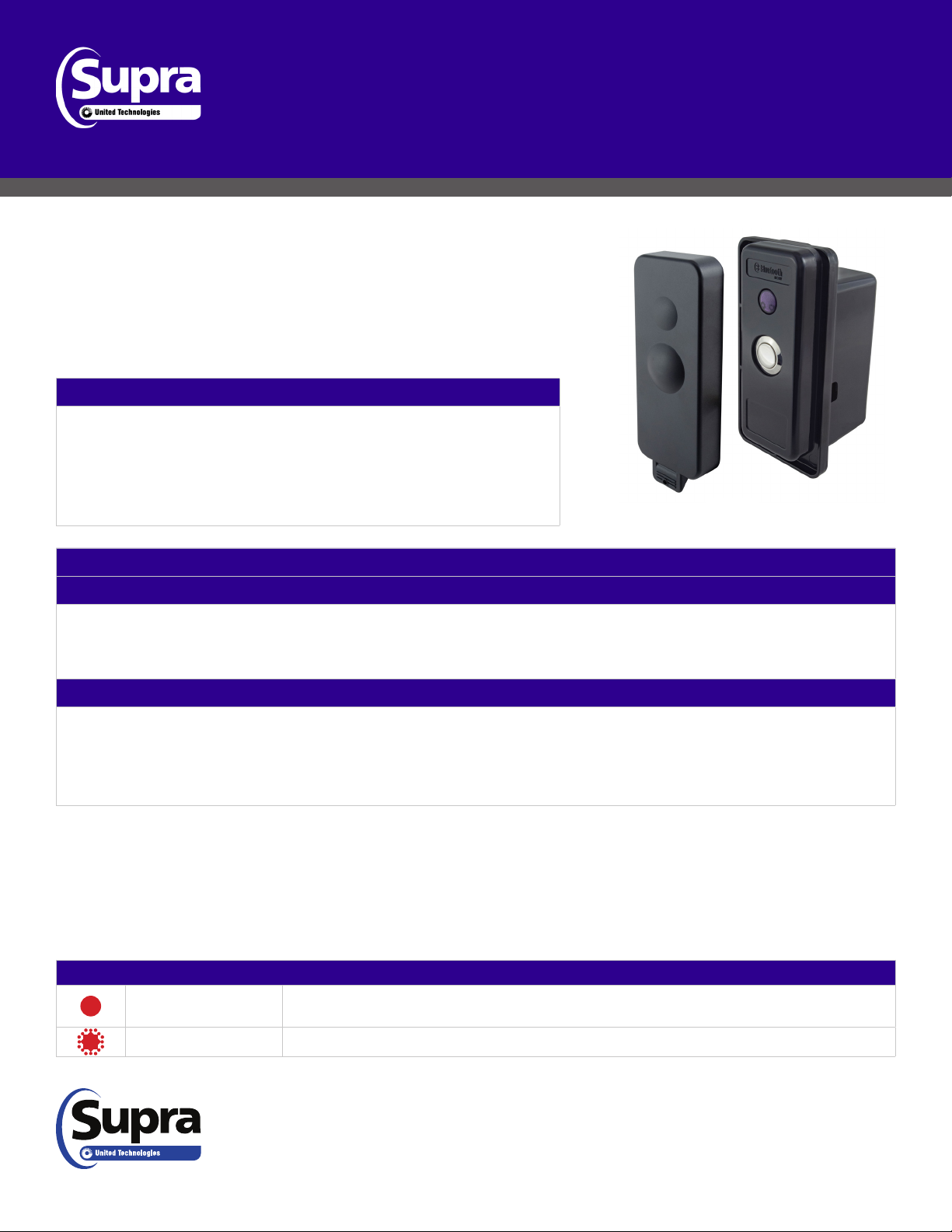
TRAC-Mini
Product Overview
Supra® TRACcess® TRAC-MiniTM controllers are used with electronic locks
controlled by the TRACcess Manager System.
TRAC-Mini controllers contain Bluetooth® wireless technology, enabling a
mobile key solution. With the TRACcess eKEYTM mobile app and Bluetooth
feature, users can securely open Supra-controlled locks.
Product Features
• TRACcess Manager with eKEY app compatible devices
• Bluetooth LE Technology and IrDA
• Lock types supported - solenoid, motorized, magnetic, and swing bolt
• FCC, IC, CE
TM
Controller
Installation User Manual
TRAC-Mini
Bezel Cover
TRAC-Mini
Controller
Congurable Product Settings
Option 1 - Pulse Mode (no hold)
This option contains one factory-installed 3V battery, which lasts the life of the product. Using a charge pump, the
circuit charges to 24V and is applied to a solenoid lock. When the TRAC-Mini battery is low, a low-battery notication
is sent to the TRACcess Administrator through the TRACcess Manager System and the TRACcess electronic key.
Option 2 - Relay Mode (7 seconds hold or 60 seconds hold)
This option contains one factory-installed 3V battery and requires a latching relay. The controller supplies a 24V
SET pulse to a latching relay, that connects an external power source (not supplied) to drive the lock. The controller
supplies 24VDC to a latching relay a second time, through the RESET line seven (7) or 60 seconds later. TRACcess
Manager low-battery notications are specically for the TRAC-Mini controller 3V battery and not for external power.
Recommendation: Select the seven (7) seconds option for a single lock and the 60 seconds option for multiple locks.
These instructions are applicable to the door, surface, and cabinet mount installation of a TRAC-Mini product. If the
TRAC-Mini components are not mounted accurately, it will not function properly. Supra is not responsible for replacing the
TRAC-Mini product or its components if it is damaged or destroyed during installation or removal. For more information,
navigate to www.suprasystems.com/Products/Pages/TRACcess_User_Resources.aspx.
Light Indicators
Light Description
Slow Red
The red LED ashes slowly when the activation button is pressed and device is seeking to
establish a connection.
Flashing Red The red LED ashes quickly three times to signal the communication seeking time has ended.
© 2018 United Technologies Corporation. All rights reserved. Supra is part of UTC Climate, Controls & Security, and a unit of United
Technologies Corporation. iOS is a registered trademark of Cisco Systems, Inc. Android is a trademark of Google LLC. Bluetooth is
a registered trademark of Bluetooth SIG. Other brand and product names are or may be the trademarks of, and are used to identify
products or services of, their respective owners. P/N 10104737P1, EN
TRAC-Mini Controller Installation User Manual
1
Page 2
Product Specications
Hardware
Hardware Specications
• External bezel dimensions:
3.84”L X 1.5”W X .05”D
• External mounting plate dimensions:
4.35”L X 2.25”W X 0.25”D
• Controller internal dimensions:
4.25”L X 2.25”W X 1.25”D
• Controller external dimensions:
4.375”L X 2.25”W X 2.125”D
Software
Software Specications
• Operating systems supports:
Apple® iOS® and AndroidTMOS
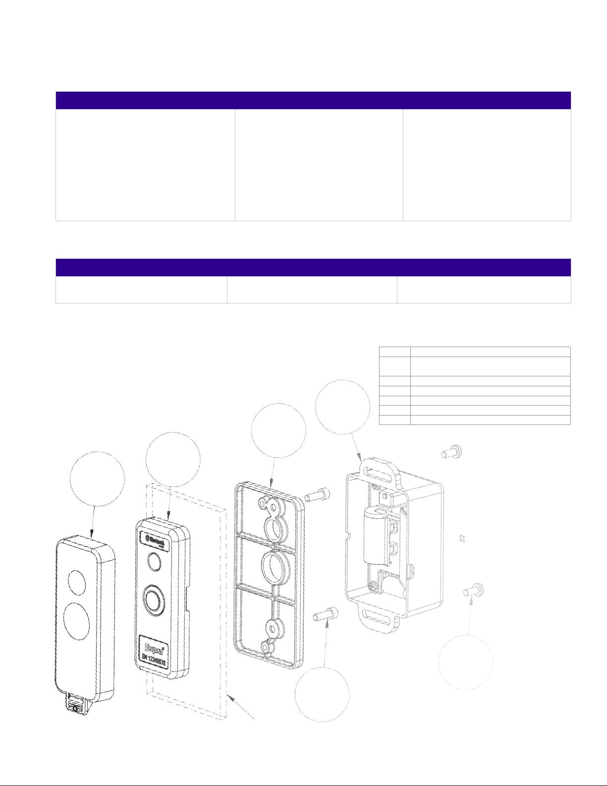
Exploded Diagram
• Input power, controller:
3V battery
• Operational temperature limit:
– 22° to 167°F (– 30°to 75°C)
• Bluetooth range: 3 ft. /1 m • IrDA range: 24 in. / 61 cm
• Storage temperature limit:
– 40° to 185°F (– 40° to 85°C)
• Option 1, Pulse Mode: SET only.
24V @ 680 μf
• Option 2, Relay Mode: SET and
RESET output. 24V @ 50mA
max., for 20 ms each
B
Callout Description
A SCREW, #8-32 X 0.375 INCH, PN, PH, STL, ZN/
CLRIR, ROHS
B PL, COVER, BEZEL, TRAC-MINI
C MTL, PLATE, MOUNT, TRAC-MINI
E
D SCREW, #8-32 X .500, SHCS
E ASSY, TRACCESS, WIRELESS CONTROLLER
F ASSY, BEZEL, TRAC-MINI
C
F
TRAC-Mini Controller Installation User Manual
A
D
Mount
Surface
2
Page 3

TRAC-Mini Wiring
Wiring Colors
Red (R) - Wire for SET when used with
a latching relay and positive polarity
with a solenoid
Note: All wires are 22 gauge.
BTLE/IrDA
Button
(Y)
(Y)
Controller
3V Battery
Note: Reset wire is not used.
White (W) - Wire for RESET when
used with a latching relay and is not
used with a solenoid lock
Option 1 - Pulse Mode
SET (R)
Ground (B)
Solenoid
Spring Lock
Option 2 - Relay Mode
Black (B) - Ground wire
Yellow (2) - Button wires, non-polarized
Not Provided
Button
(Y)
(Y)
BTLE/IrDA
Controller
3V Battery
User
Application
Relay
SET (R)
RESET (W)
Ground (B)
External Power
Source
+
Coil
24V
Latching Relay
-
Lock
Installation Requirements
This section provides step-by-step instructions to install the TRAC-Mini controller. Read through these instructions before
performing any installation steps. Verify all components are not energized when connecting wiring or during assembly.
Accurate mounting is essential for the TRAC-Mini to function properly, see the TRAC-Mini Controller Drill Template.
Best Practice: For externally powered locks, hard-wire the latching relay to the facility power to reduce the risk of lock failure.
The TRAC-Mini controller is designed to be installed above, below, or to the side of the lockset. In extremely hot climates,
place the TRAC-Mini controller in the shade to prevent it from becoming too hot, which may reduce battery life. In extremely
cold weather conditions, place the TRAC-Mini controller where it can be protected from harsh climate and precipitation.
Sealant Selection (Surface Mount) Mounting Surface Condition and Preparation
For protection against moisture, choose a sealant that is
compatible with the mounted surface and includes these
requirements.
• Choose sealants appropriate for sealing surfaces
• Waterproof
• Exterior rated
• UV resistant
Best Practice: Installation 6 in. (15 cm) above the lockset, or as far above the lockset as needed to be out of the way of
door hardware. Install the lockset per manufacturer’s instructions.
Prepare the surface per the sealant manufacturer’s instructions.
• Suitable for sealing
• Free of loose material
• Clean and dry
• Flat and free of irregularities
• Use and apply sealants per the Manufacturer’s instructions
TRAC-Mini Controller Installation User Manual
3
Page 4

Required Skills
A General Mechanical/Electrical Technician skill level is required to perform the installation procedures.
Required Tools and Equipment
QTY Description QTY Description
1 Pen (or pencil) 1 Wrench, Hex Key, 9/64”
1 Level A/R Connectors, wire (not provided), as required
1 Drill (or punch) 1 Screwdriver, Phillips
A/R Drill bits, as required per drill template 1 Relay, latching, 24V, (optional per setup)
A/R Sealant (optional), as required A/R File, as required
Reference Documentation
Nomenclature Document Number
TRAC-Mini Controller Drill Template 10104943P1
Prerequisites
The TRACcess eKEY app is required to congure the controller. For more information on how to download and
authorize the TRACcess eKEY app go to www.traccessmanager.com and click User resources: downloads, videos and
more.
Technical Support
For technical support in the U.S., call 1-800-689-9896 (5 a.m. to 7 p.m., Pacic Standard Time, 7 days a week) or
contact your sales representative.
Install the Controller
Step Action
1. Record the serial number of the TRAC-Mini controller for record keeping.
2. Using the drill template (10104943P1) and level, position the template to drill holes for the surface.
3. Using the drill and drill bit, drill holes through the template into the surface.
4. If applying sealant, apply sealant to the exterior mounted bezel assembly (F).
5. Pass two (2) yellow button wires from the bezel assembly through the center drill hole.
6. Using a Hex Key wrench and two (2) #8-32 x .5 screws (D), attach the bezel to the mounting surface and the mounting
plate (C).
7. Attach the yellow button wires from the bezel assembly to the yellow wires from the TRAC-Mini controller (E) and
secure with wire connectors, as required.
8. Trim, tuck, or coil the yellow wires and store in the recess area of the TRAC-Mini controller.
9. Using a Phillips screwdriver and two (2) #8-32 x .375 screws (A), attach the TRAC-Mini controller to the mounting plate.
Note: When connecting to a solenoid lock, the white wire is not used. Connect the red and black wires to the lock wires,
respectively. When connecting to a latch relay, all three control wires (red, black, and white) are connected to their
corresponding lock wires.
10. Connect the TRAC-Mini controller wires to the solenoid (or relay wires) and cap with wire connectors.
11. Attach the TRAC-Mini bezel cover (B), as required.
TRAC-Mini Controller Installation User Manual
4
Page 5

Congure TRAC-Mini Controller
Step Action
1. From your device app store, download and then authorize the TRACcess eKEY app.
2. Open the eKEY app and tap Settings.
3. Check Install Mode and Save.
4. Tap Install.
5. Enter the eKEY app PIN (or device access code) and tap Begin.
Note: If the wrong setting is installed, perform the install function again (begin at step 2) to reset the setting.
6. Choose the appropriate programming mode for the lock.
Open the Lock
Direct sunlight can interfere with infrared communication; shade the area between the lock and key when using this feature.
For more information on using TRACcess eKEY, see the TRACcess User Resources page found at www.suprasystems.com/
Products/Pages/TRACcess_User_Resources.aspx.
Step Action
1. On the TRACcess eKEY app, tap Open Device.
2. Enter the PIN code.
3. Enter the access code, if required.
4. Press the TRAC-Mini controller button to turn it on.
5. Tap Begin.
General Maintenance
Step Action
CAUTION! Do not use harsh chemicals when cleaning the controller.
1. Visually inspect the TRAC-Mini controller and bezel for damage and replace as required.
2. Using a clean cloth, wipe down the controller exterior and bezel.
TRAC-Mini Controller Battery
The TRAC-Mini controller uses a long-life lithium battery to power the SET and RESET button or solenoid lock. No battery
maintenance is required and the battery is designed to last a minimum of six (6) years. Replace the controller when the
battery is spent.
Dispose of all batteries as required by local ordinances, regulations, and/or the latest WEEE and European
2012/19/CE requirements. Do not throw batteries in the common garbage.
TRACcess Manager shows the battery status for TRAC-Mini controllers (low-battery notications are specically for the 3V
battery and not for external power). A low battery warning message for the TRAC-Mini controller also displays on the eKEY
mobile app. Make sure to take steps to monitor battery levels regularly.
TRAC-Mini Controller Installation User Manual
5
Page 6

WARNING! If locks are not hard-wired to facility power and batteries lose power, the locks may not open. Make
sure to take steps to monitor lock and controller battery levels regularly.
Environmental Compliance
Supra controllers adhere to environmental regulations established by the current European Union (EU) RoHS, WEEE, and
REACH directives.
above 0.1%, and hereby certify that its products are in full compliance with all aspects of Commission Regulation (EU)
2017/999 of 13 June 2017 amending Annex XIV to Regulation (EC) No 1907/2006 of the European Parliament and of the
Council concerning the Registration, Evaluation, Authorization and Restriction of Chemicals (REACH).
Label Example
• FCC, IC, CE
• AS/NZS 4268:2012 +A1:2013
• EN 300 328 V2.1.1:2016
• EN 301 489-17 V3.1.1:2017
• FCC 15.247:2018
• RSS-247:2017
Regulatory
Controllers are listed below. Do not confuse this regulatory number with the marketing name or product part numbers.
Regulatory Model
Number (RMN)
Lock Family Name Description
10106056P1 TRACcess Controllers TRAC-Mini 10106057P1
Regulatory Statements
United States
(FCC)
Canada (IC) This device complies with Industry Canada’s license-exempt RSSs. Operation is subject to the following two
European Union
(CE)
This device complies with part 15 of the FCC rules. Operation is subject to the following conditions:
1. This device may not cause harmful interference.
2. This device must accept any interference received, including interference that may cause undesired
operation.
authority to operate the equipment.
conditions:
1. This device may not cause interference; and
2. This device must accept any interference, including interference that may cause undesired operation of
the device.
Cet équipement est conforme á Ia (aux) norme(s) canadienne(s) d’exemption de licence RSS Industry Canada.
Son opération est sujette aux deux conditions suivantes: (1) cet équipement ne provoquera aucune interference el
(2) cet équipement doit tolérer toute in interférence pouvant provoquer une opération indésirable de I’equipement.
This Class B digital apparatus conforms to the requirements of the following EU directives:
1. RED, 2.4GHz, Bluetooth Power class 1
2. WEEE Directive (2012/19/EC)
3. Frequency Range: 2402MHz - 2480MHz. Output Power: 8dBm.
Commercial Model Number
(CMN)
TRAC-Mini Controller Installation User Manual
6
 Loading...