


UTC UTCTA31001 Datasheet
UTC TA31001 LINEAR INTEGRATED CIRCUIT
TELEPHONE TONE RINGER
DESCRIPTION
The UTC TA31001 is a bipolar integrated circuit
designed for telephone bell replacement. It can also be
used as alarms or other alerting devices.
FEATURES
*Designed for telephone bell replacement.
*Low current drain for multiple extension of lines.
*Adjustable 2-frequency tone.
*Adjustable warbling rate.
*Built-in hysteresis prevents false triggering and
rotary dial 'CHIRPS'.
*Programmable for initiation voltage by simple
external resistor.
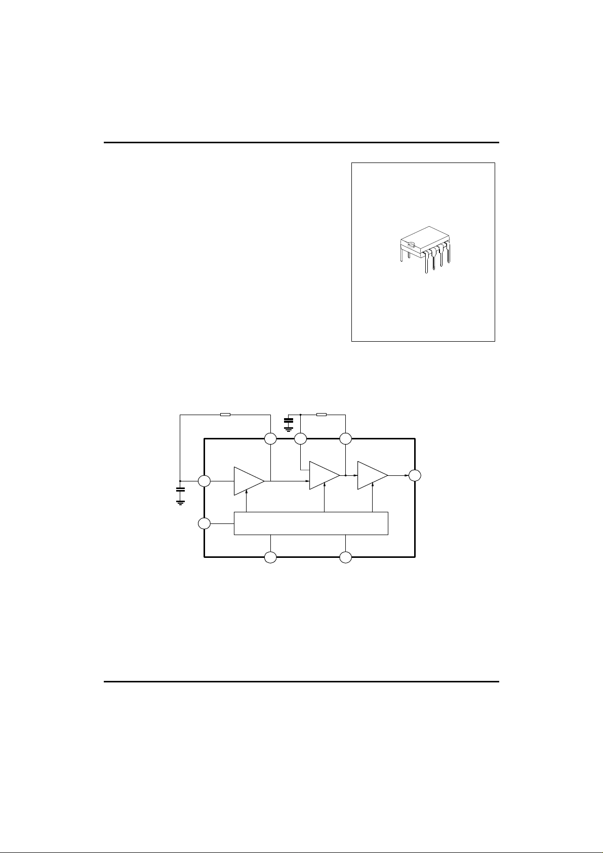
BLOCK DIAGRAM
DIP-8
R2
C2
3
1
LOW
OSC
Note:R2,R3,C2 and C3 are parts externally mounted
C3
POWER SUPPLY (WITH HYSTERESIS)
5 2
HIGH
OSC
R3
674
AMP
8
OUTPUT
UTC UNISONIC TECHNOLOGIES CO. LTD
1
QW-R108-003,A
UTC TA31001 LINEAR INTEGRATED CIRCUIT
ABSOLUTE MAXIMUM RATINGS(Ta=25°C )
Supply Voltage Vcc 30 V
Power Dissipation Pd 400 mW
Operating Temperature Topr -45 to 85
Storage Temperature Tstg -65 to 150
ELECTRICAL CHARACTERISTICS( Ta=25°C )
(All voltage referenced to GND unless otherwise specified)
Operating Supply Voltage Vcc 29 V
Initiation Supply Voltage (note 1) Vsi See Fig.2 17 19 21 V
Initiation Supply Current (note 1) Isi 6.8K-Pin 2 to GND 1.4 3.5 4.2 mA
Sustaining Voltage (note 2) Vsus See Fig.2 9.7 11 12 V
Sustaining Current (note 2) Isus No Load Vcc=Vsus,See Fig.2 0.7 1.4 2.5 mA
Output Voltage High VOH Vcc=21V, I8=-15mA
Output Voltage Low VOL Vcc=21V, I8=15mA
IIN(Pin 3)
IIN(Pin 7)
High Frequency 1 FH1 R3=191K, C3=6800pF 461 512 563 Hz
High Frequency 2 FH2 R3=191K, C3=6800pF 576 640 704 Hz
Low Frequency FL
*NOTE (See electrical characteristics sheet)
1. Initiation supply voltage (Vsi) is the supply voltage required to start the tone ringer oscillating.
2. Sustaining voltage (Vsus) is the supply voltage required to maintain oscillation.
PARAMETER SYMBOL VALUE UNIT
°C
°C
PARAMETER SYMBOL TEST CONDITIONS MIN TYP MAX UNIT
17.0 19 21 V
Pin6=6V, Pin7=GND
1.6 V
Pin6=GND, Pin7=6V
Pin3=6V, Pin4=GND
Pin7=6V, Pin6=GND
R2=165K, C2=0.47µF
-
-
-
500
500nAnA
-
9 10 11 Hz
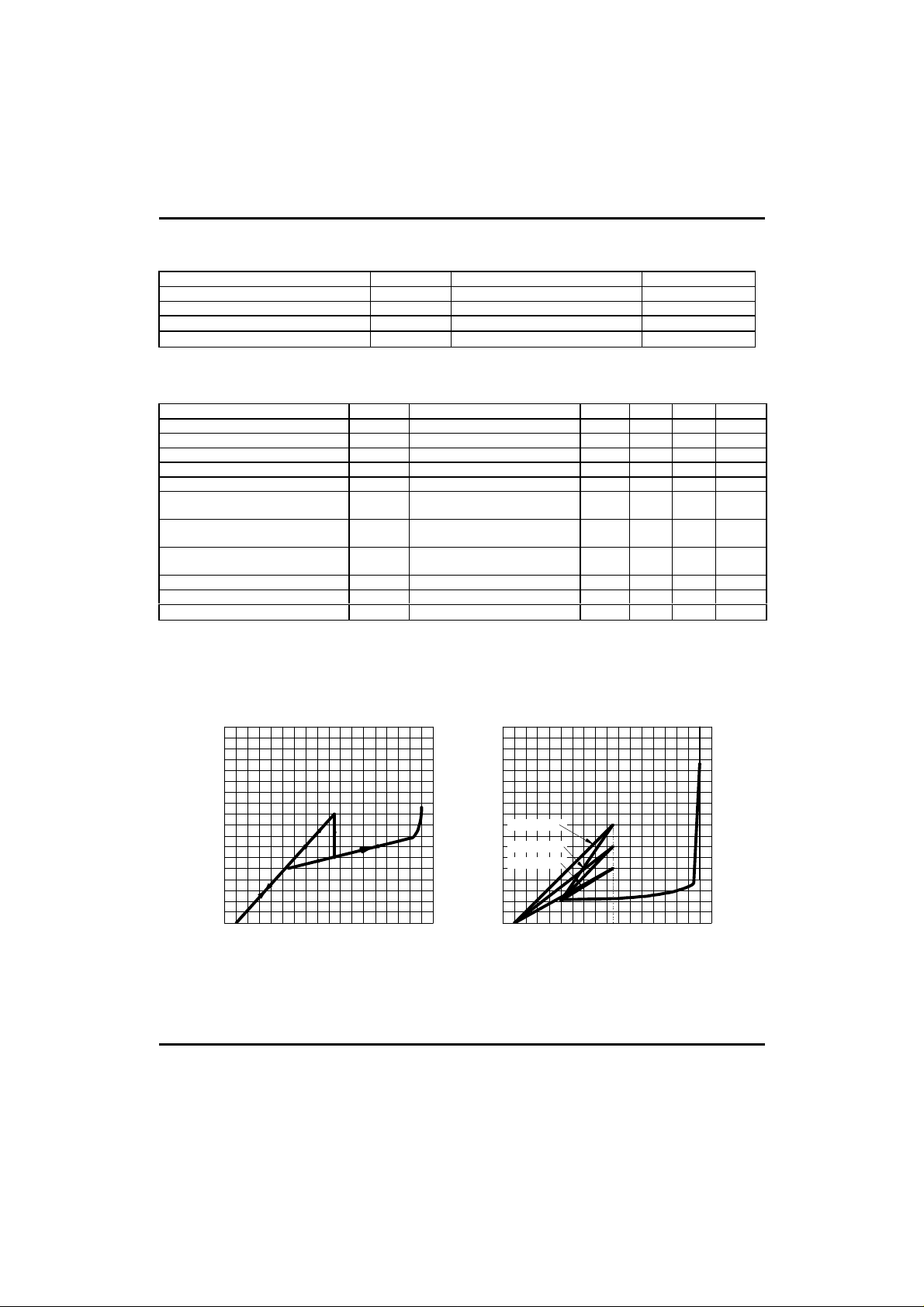
4.0
3.5
3.0
2.5
2.0
1.5
1.0
Icc(mA),Supply Current
0.5
Circuit Current-Supply Voltage
(No Load)
Vcc(V),Supply voltage
Supply Current (mA)
34302622181410 6 2 34302622181410 6 2
Supply Current Vs. Supply Voltage
8.5
7.5
6.5
5.5
4.5
A:RSL=5K
3.5
B:RSL=6.8K
C:RSL=13K
2.5
1.5
0.5
Vcc(V),Supply voltage
(No Load)
Fig. 1 Fig. 2
UTC UNISONIC TECHNOLOGIES CO. LTD
34302622181410 6 2 34302622181410 6 2
2
QW-R108-003,A