

UTC NE556 LINEAR INTEGRATED CIRCUIT
DUAL TIMER
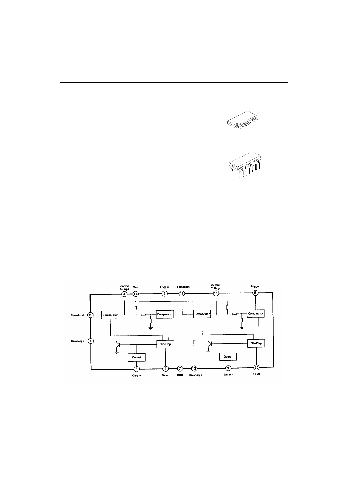
DESCRIPTION
The UTC NE556 dual monolithic circuit is a highly
stable controller capable of producing accurate delays
or oscillation. The UTC NE556 is the dual of UTC
NE555; timing is provided an external resistor and
capacitor for each function. The two timers operate
independently of each other, sharing only Vcc and
GND. The circuits may be triggered and reset on falling
wave forms. The output structures may sink or source
200mA.
FEATURES
*High current driver capability(=200mA)
*Adjustable duty cycle
*Timing from µSec to Hours
*Temperature stability of 0.005%/°C
*TTL compatible
*Operates in both Astable and Monostable modes
APPLICATIONS
*Precision timing. *Pulse width modulation.
*Pulse generator, shaping. *Traffic light control.
*Time delay generator. *Touch tone encoder.
*Sequential timing. *Tone burst generator.
SOP-14
DIP-14
BLOCK DIAGRAM
UTC UNISONIC TECHNOLOGIES CO., LTD.
QW-R106-002,A
1
UTC NE556 LINEAR INTEGRATED CIRCUIT
ABSOLUTE MAXIMUM RATINGS(Ta=25°C )
Supply Voltage Vcc 16 V
Power Dissipation Pd 600 mW
Lead Temperature(soldering 10
sec.)
Operating Temperature Topr -40~85
Storage Temperature Tstg -65~150
ELECTRICAL CHARACTERISTICS
( Ta=25°C ,Vcc=5 to 15V, unless otherwise specified)
Supply voltage Vcc 4.5 16 V
Supply Current(two timers) Icc
(low state), (Note 1)
Timing Error(monostable)
Initial Accuracy(Note 2) ACCUR
Drift with Temperature
Drift with Supply Voltage
Timing Error(astable)
Initial Accuracy(Note 2) ACCUR
Drift with Temperature
Drift with Supply Voltage
Control Voltage Vc Vcc=15V 9.0 10.0 11.0 V
Threshold Voltage VTH Vcc=15V 8.8 10.0 11.2 V
Threshold Current(Note 3) ITH 30 250 nA
Trigger Voltage Vtr Vcc=5V 1.1 1.6 2.2 V
Trigger Current Itr Vtr=0 0.01 2.0
Reset Voltage(Note 4) Vrst 0.4 0.6 1.0 V
Reset Current Irst 0.03 0.6 mA
Low Output Voltage VOL Vcc=15V
High Output Voltage VOH Vcc=15V
PARAMETER SYMBOL VALUE UNIT
Tlead 300
°C
°C
°C
PARAMETER SYMBOL TEST CONDITIONS MIN TYP MAX UNIT
Vcc=5V,RL=∝
Vcc=15V,RL=∝
RA=2KΩ to 100KΩ
C=0.1µF
T=1.1RC
∆t/∆T
∆t/∆Vcc
RA=1KΩ to 100KΩ
C=0.1µF
Vcc=15V
∆t/∆T
∆t/∆Vcc
Vcc=5V 2.6 3.33 4.0 V
Vcc=5V 2.4 3.33 4.2 V
Vcc=15V 4.5 5 5.6 V
Isink=10mA
Isink=50mA
Isink=100mA
Isink=200mA
Vcc=5V
Isink=5mA
Isink=8mA
Isource=200mA
Isource=100mA
5 12 mA
16 30 mA
0.75 %
50
0.1 %/V
2.25 %
150
0.3 %/V
0.1 0.25 V
0.4 0.75 V
2 3.2 V
2.5 V
0.15 0.25 V
0.25 0.35 V
ppm/°C
ppm/°C
µA
UTC UNISONIC TECHNOLOGIES CO., LTD.
QW-R106-002,A
2

UTC NE556 LINEAR INTEGRATED CIRCUIT
PARAMETER SYMBOL TEST CONDITIONS MIN TYP MAX UNIT
Vcc=5V
Isource=100mA
Rise Time of Output tR 100 300 nSec
Fall Time of Output tF 100 300 nSec
Discharge Leakage Current ILKG 20 100 nA
Matching Parameter
Initial Accuracy(Note 5) ACCUR
Drift with Temperature
Drift with Supply Voltage
Note 1: Supply current when output is high is typically 1mA less at Vcc 5V.
Note 2: Tested at Vcc=5V and Vcc=15V.
Note 3: This will determine the maximum value of RA+RB for 15V operation, The maximum total is R=20MΩ, and
∆t/∆T
∆t/∆Vcc
RA, RB=1KΩ to 100KΩ
C=0.1µF
Vcc=15V
12.75 13.3 V
for 5V operation the maximum total is R=6.6MΩ.
Note 4: As reset voltage lower, timing is inhibited and then the output goes low.
Note 5: Matching parameters refer to the difference between performance parameters of each timer section in the
monostable mode.
12.5 V
2.75 3.3 V
1 2 %
10
0.2 0.5 %/V
ppm/°C
UTC UNISONIC TECHNOLOGIES CO., LTD.
QW-R106-002,A
3
 Loading...