

UTC UTCMCR100-8, UTCMCR100-6, UTCMCR100-4 Datasheet
UTC MCR100 SCR
UTC UNISONIC TECHNOLOGIES CO., LTD.
1
PLASTIC SILICON
CONTROLLED RECTIFIERS
DESCRIPTION
PNPN devices designed for high volume, linepowered consumer applications such as relay and
lamp drivers, small motor controls, gate drivers for
larger thyristors, and sensing and detection circuits.
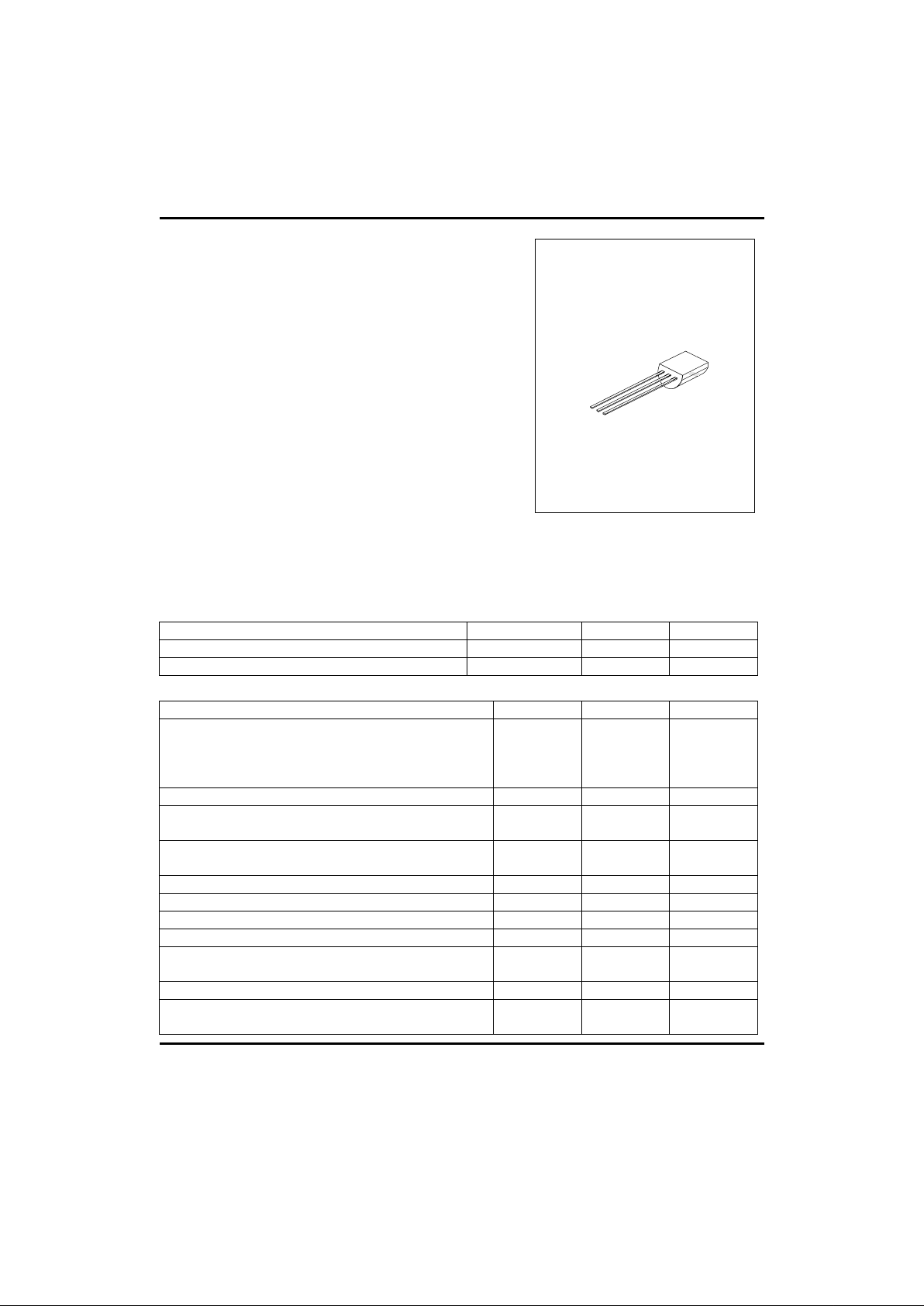
Supplied in an inexpensive plastic TO-92 package
which isreladily adaptable for use in automatic
insertion equipment.
DESCRIPTION
*Sensitive Gate Trigger Current - 200µA Maximum
*Low Reverse and forward Blocking Current - 100µA
Maximum, Tc=125°C
*Low Holding Current – 5mA Maximum
*Glass-Passivated Surface for Reliability and
Uniformity
*Also Available with TO-5 or TO-18 Lead Form
TO-92
1
1:CATHODE 2:GATE 3:ANODE
THERMAL CHARACTERISTICS
PARAMETER SYMBOL MAX UNIT
Thermal Resistance, Junction to Case
R£cJC
75 °C/W
Thermal Resistance, Junction to Ambient
R£cJA
200 °C/W
ABSOLUTE MAXIMUM RATINGS
PARAMETER SYMBOL MAX UNIT
Peak Reverse Blocking Voltage
MCR100-4
MCR100-6
MCR100-8
VRRM
200
400
600
V
Forward Current RMS IT(RMS) 0.8 A
Peak Forward Surge Current, TA=25°C
(1/2 cycle, Sine Wave, 60Hz)
ITSM 10 A
Circuit Fusing Considerations, TA=25°C
(t=1 to 8.3 ms)
I2t 0.415 A2s
Peak Gate Power – Forward, TA=25°C PGM 0.1 W
Average Gate Power – Forward, TA=25°C PGF(AV) 0.01 W
Peak Gate Current – Forward, TA=25°C(300µs, 120PPS) IGFM 1 A
Peak Gate Voltage - Reverse VGRM 5 V
Operating Junction Temperature Range @ Rated VRRM and
VDRM
Tj -65 to +110 °C
Storage Temperature Range Tstg -40 to +150 °C
Lead Solder Temperature
(<1/16” from case, 10 s max)
230 °C

UTC MCR100 SCR
UTC UNISONIC TECHNOLOGIES CO., LTD.
2
ELECTRICAL CHARACTERISTICS (Tj=25°C unless otherwise stated)
PARAMETER SYMBOL MIN MAX UNIT
Peak Forward Blocking Voltage
(Tc=125°C) MCR100-4
MCR100-6
MCR100-8
VDRM
200
400
600
V
Peak Forward or Reverse Blocking Current
(Rated VDRM or VRRM) Tc=25°C
Tc=125°C
IDRM,IRRM
10
100
µA
µA
Forward “On” Voltage (Note1)
(ITM=1A peak @ TA=25°C)
VTM 1.7 V
Gate Trigger Current (continuous dc) (Note 2) Tc=25 °C
(Anode Voltage=7Vdc, RL=100Ω)
IGT 200 µA
Gate Trigger Voltage (continuous dc) Tc=25 °C
(Anode voltage=7Vdc, RL=100Ω) Tc=-40 °C
(Anode Voltage=Rated VDRM, RL=100Ω) Tc=125 °C
VGT
0.1
0.8
1.2
V
Holding Current Tc=25 °C
(Anode Voltage=7Vdc, initiating current=20mA) Tc=-40 °C
IH 5
10
mA
Notes: 1. Forward current applied for 1 ms maximum duration, duty cycle <=1%
2. RGK current is not included in measurement.
 Loading...