

UTC 2SA733 NPN EPITAXIAL SILICON TRANSISTOR
UTC UNISONIC TECHNOLOGIES CO. LTD
1
LOW FREQUENCY AMPLIFIER
PNP EPITAXIAL SILICON
TRANSISTOR
DESCRIPTION
The UTC 2SA733 is an low frequency amplifier.
FEATURES
*Collector-Emitter voltage:
BVCBO=-50V
*Collector current up to –150mA
*High hFE linearity
*Complimentary to 2SC945
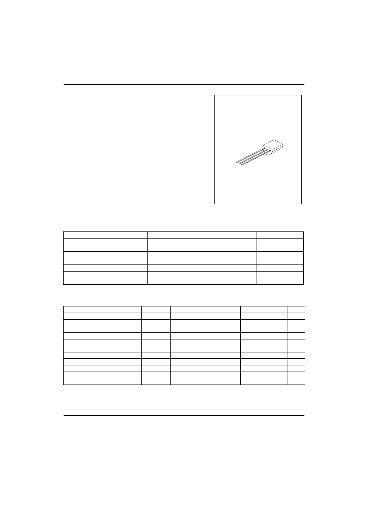
TO-92
1
1:EMITTER 2:COLLECTOR 3: BASE
ABSOLUTE MAXIMUM RATINGS ( Ta=25°C ,unless otherwise specified )
PARAMETER SYMBOL VALUE UNIT
Collector-Base Voltage VCBO -60 V
Collector-Emitter Voltage VCEO -50 V
Emitter-Base Voltage VEBO -5 V
Collector Dissipation(Ta=25°C) Pc 250 mW
Collector Current Ic -150 mA
Junction Temperature Tj 125 °C
Storage Temperature TSTG -55 ~ +150 °C
ELECTRICAL CHARACTERISTICS(Ta=25°C,unless otherwise specified)
PARAMETER SYMBOL TEST CONDITIONS MIN TYP MAX UNIT
Collector-Base Breakdown Voltage BVCBO Ic=-100µA, IE=0 -60 V
Collector-Emitter Breakdown Voltage BVCEO IC=-10mA,IB=0 -50 V
Collector Cut-Off Current ICBO VCB=-40V,IE=0 -100 nA
Emitter Cut-Off Current IEBO VEB=-3V,Ic=0 -100 nA
DC Current Gain(note) hFE1 VCE=-6V,Ic=-1mA 90 600
Collector-Emitter Saturation Voltage VCE(sat) Ic=-100mA,IB=-10mA -0.1 -0.3 V
Current Gain Bandwidth Product fT VCE=-10V,Ic=-50mA 100 190 MHz
Output Capacitance Cob VCB=-10V,IE=0,f=1MHz 2.0 3.0 pF
Noise Figure NF Ic=-0.1mA,VCE=-6V
RG=10kΩ,f=100Hz
4.0 6.0 dB
UTC 2SA733 NPN EPITAXIAL SILICON TRANSISTOR
UTC UNISONIC TECHNOLOGIES CO. LTD
2
CLASSIFICATION OF hFE
RANK R Q P K
RANGE 90-180 135-270 200-400 300-600
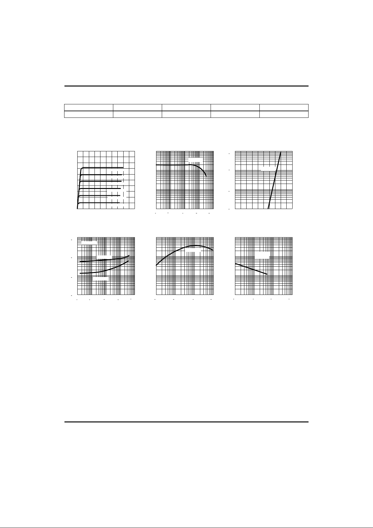
TYPICAL PERFORMANCE CHARACTERISTICS
Fig.1 Static characteristics
Collector-Emitter voltage ( V)
Ic,Collector current (mA)
0 -4 -8 -12 -16 -20
0
-20
-40
-60
-80
-100
Fig.2 DC current Gain
Ic,Collector current (mA)
H
FE
, DC current Gain
10
2
10
1
10
0
10
3
10
3
10
2
10
1
10
0
10
-1
VCE=-6V
Fig.3 Base-Emitter on Voltage
10
-1
10
0
10
1
10
2
Ic,Collector current (mA)
Base-Emitter voltage (V)
0 -0.2 -0.4 -0.6 -0.8 -1.0
VCE=-6V
Ic,Collector current (mA)
10
3
10
2
10
1
10
0
10
-1
Saturation voltage (MV)
10
1
10
2
10
3
10
4
Fig.4 Saturation voltage
Fig.5 Current gain-bandwidth
product
Fig.6 Collector output
Capacitance
VCE(sat)
VBE(sat)
Ic=10*I
B
Ic,Collector current (mA)
10
0
10
1
10
2
10
3
Current Gain-bandwidth
product,f
T
(MHz)
10
0
10
1
10
2
VCE=-6V
Collector-Base voltage (V)
Cob,Capacitance (pF)
10
0
10
1
10
2
10
0
10
1
10
2
10
3
f=1MHz
IE=0
IB= -50 µA
IB= -100 µA
IB= -150 µA
IB= -200 µA
IB= -250 µA
IB= -300 µA
10
-1
10
-1
 Loading...