

UNISONIC TECHNOLOGIES CO.,LTD.
TDA2822
LINEAR INTEGRATED CIRCUIT
DUAL LOW VOLTAGE
POWER AMPLIFIER
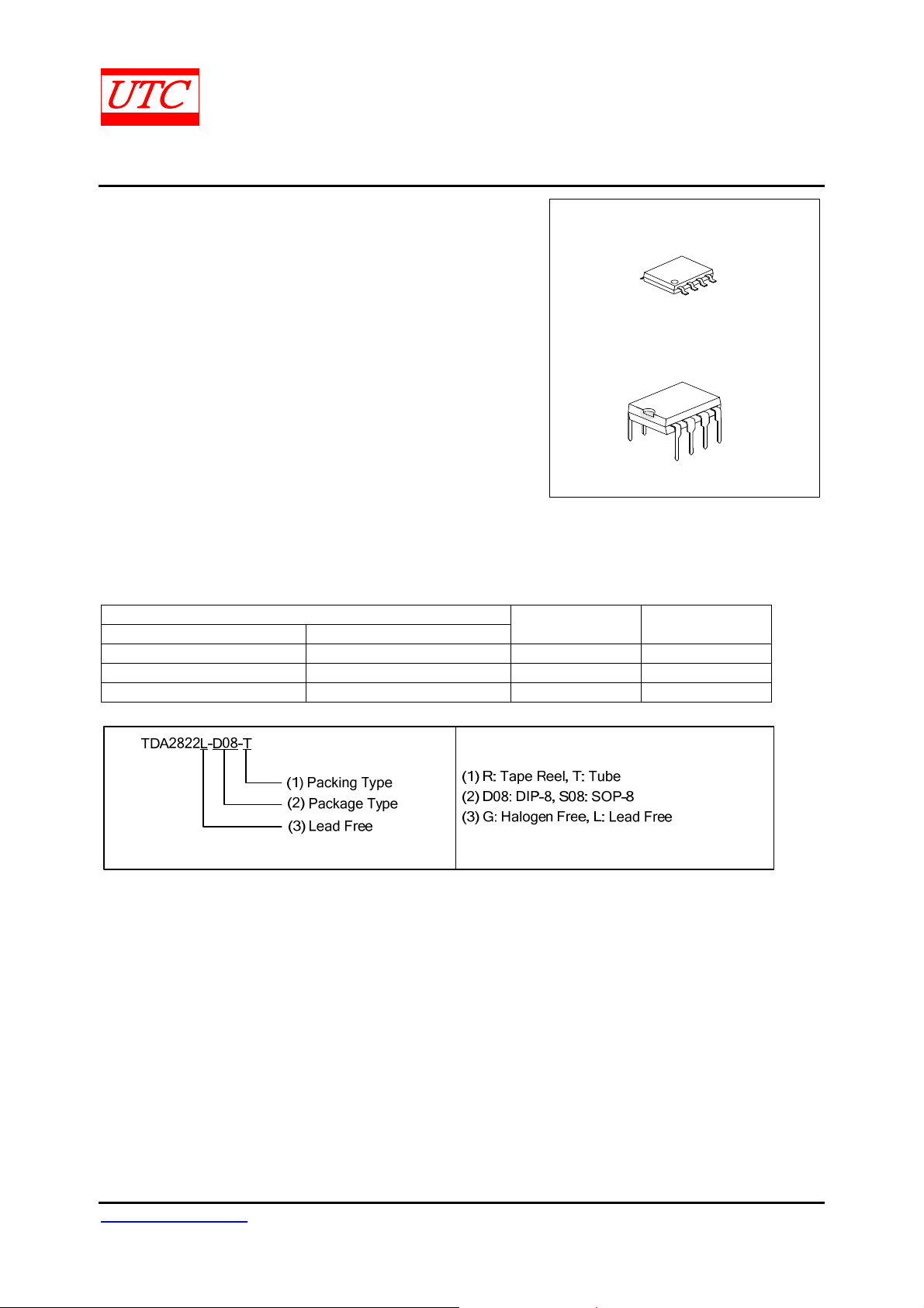
DESCRIPTION
The UTC TDA2822 is a monolithic integrated audio amplifier
in a 8-Pin plastic dual in line package. It is designed for
portable cassette players and radios.
FEATURES
* Wide Operating Supply Voltage: VCC=1.8V - 12V.
* Low Crossover Distortion.
* Low Quiescent Circuit Current.
* Bridge/Stereo Configuration.
ORDERING INFORMATION
Lead Free Halogen Free
TDA2822L-S08-R TDA2822G-S08-R SOP-8 Tape Reel
TDA2822L-S08-T TDA2822G-S08-T SOP-8 Tube
TDA2822L-D08-T TDA2822G-D08-T DIP-8 Tube
Ordering Number
SOP-8
DIP-8
Package Packing
www.unisonic.com.tw 1 of 6
Copyright © 2011 Unisonic Technologies Co.,LTD. QW-R107-006.G
TDA2822 LINEAR INTEGRATED CIRCUIT
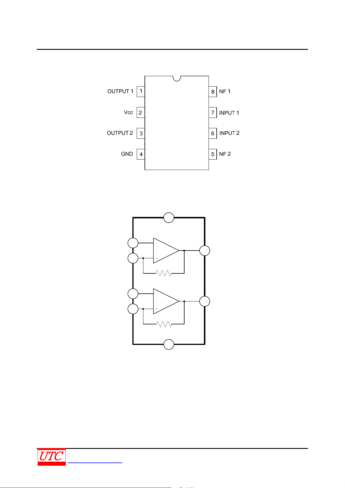
PIN CONFIGURATIONS
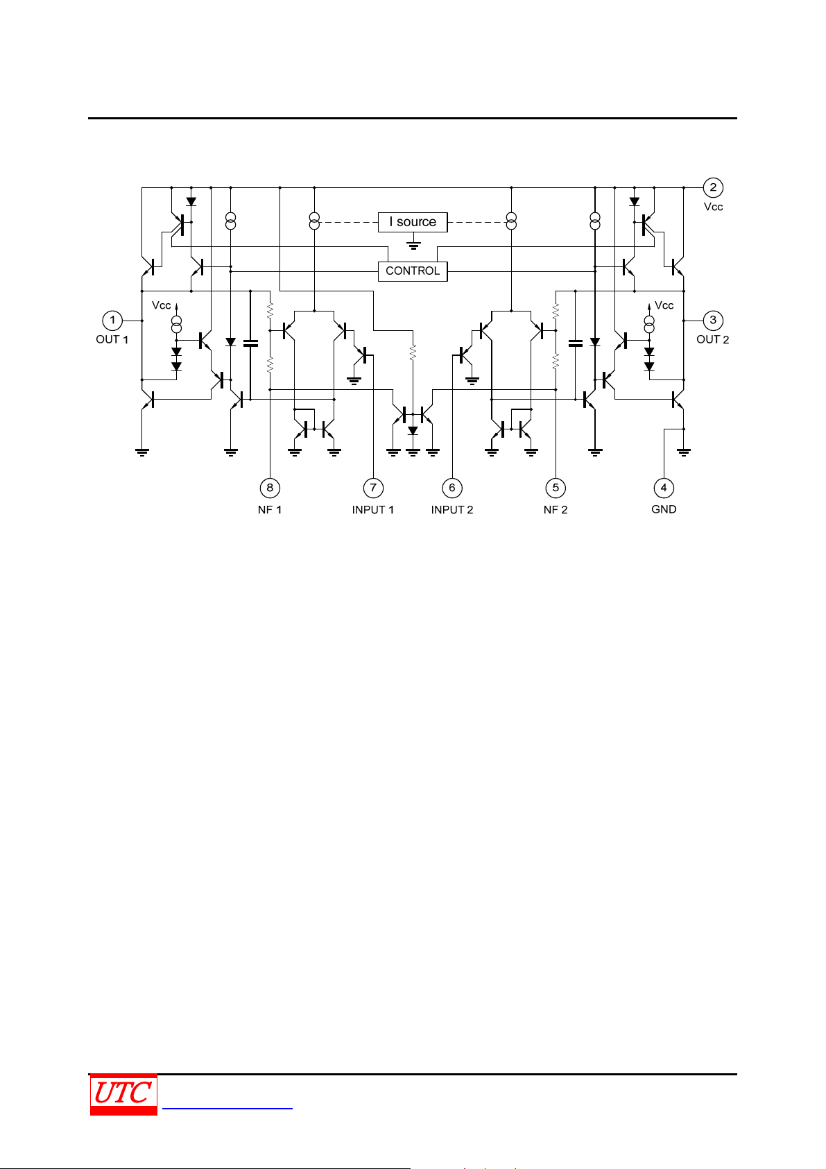
BLOCK DIAGRAM
INPUT1
NP1
INPUT2
NP2
V
CC
2
7
8
6
5
+
1
OUTPUT1
+
3
OUTPUT2
4
GND
UNISONIC TECHNOLOGIES CO., LTD 2 of 6
www.unisonic.com.tw QW-R107-006.G
TDA2822 LINEAR INTEGRATED CIRCUIT
ABSOLUTE MAXIMUM RATINGS (T
=25°C)
A
PARAMETER SYMBOL RATINGS UNIT
Supply Voltage VCC 15 V
Output Peak Current I
Power Dissipation
DIP-8 1.0
SOP-8
Operating Temperature T
Storage Temperature T
1 A
O(PEAK)
PD
-20~+85 °C
OPR
-40~+150 °C
STG
0.5
W
Note:1. Absolute maximum ratings are stress ratings only and functional device operation is not implied. The device
could be damaged beyond Absolute maximum ratings.
2. The device is guaranteed to meet performance specifications within 0℃~70℃ operating temperature range
and assured by design from -20℃~ 85℃
ELECTRICAL CHARACTERISTICS (T
=25°C, VCC=6V, f=1kHz, unless otherwise specified)
A
PARAMETER SYMBOL TEST CONDITIONS MIN TYP MAX UNIT
Operating Supply Voltage VCC 1.8 12 V
Quiescent Circuit Current ICC VIN=0 9 mA
Closed Loop Voltage Gain
Stereo 40 dB
Bridge
GVC
40 dB
Channel Balance CB Stereo -1 0 1 dB
Output Power(Stereo)
Output Power (Bridge)
Total Harmonic Distortion
DIP-8 0.4 0.65
SOP-8
DIP-8 0.11
P
SOP-8
DIP-8 0.9 1.35
SOP-8
DIP-8 0.35
P
SOP-8
Stereo RL=8Ω, P
Bridge
THD
V
=6V,RL=4Ω, THD=10%
CC
OUT
VCC=3V,RL=4Ω, THD=10%
VCC=6V,RL=4Ω, THD=10%
OUT
VCC=3V,RL=4Ω, THD=10%
=0.2W 0.5 %
OUT
R
=8Ω, P
L
=0.5W 0.5 %
OUT
0.28 0.45
0.07
0.63 0.94
0.24
W
W
W
W
Ripple Rejection RR Stereo, f=100Hz,C3=100μF 24 30 dB
Output Noise Voltage eN Stereo, BW(-3dB)=20Hz ~20kHz 0.5 2.0 mV
Cross Talk CT Stereo, f=1kHz 50 dB
Input Resistance RIN 100 kΩ
UNISONIC TECHNOLOGIES CO., LTD 3 of 6
www.unisonic.com.tw QW-R107-006.G
TDA2822 LINEAR INTEGRATED CIRCUIT
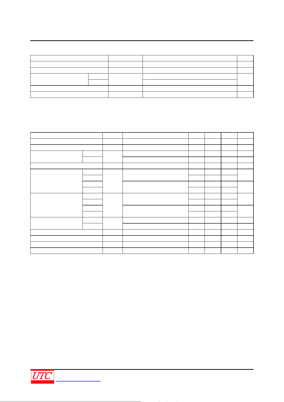
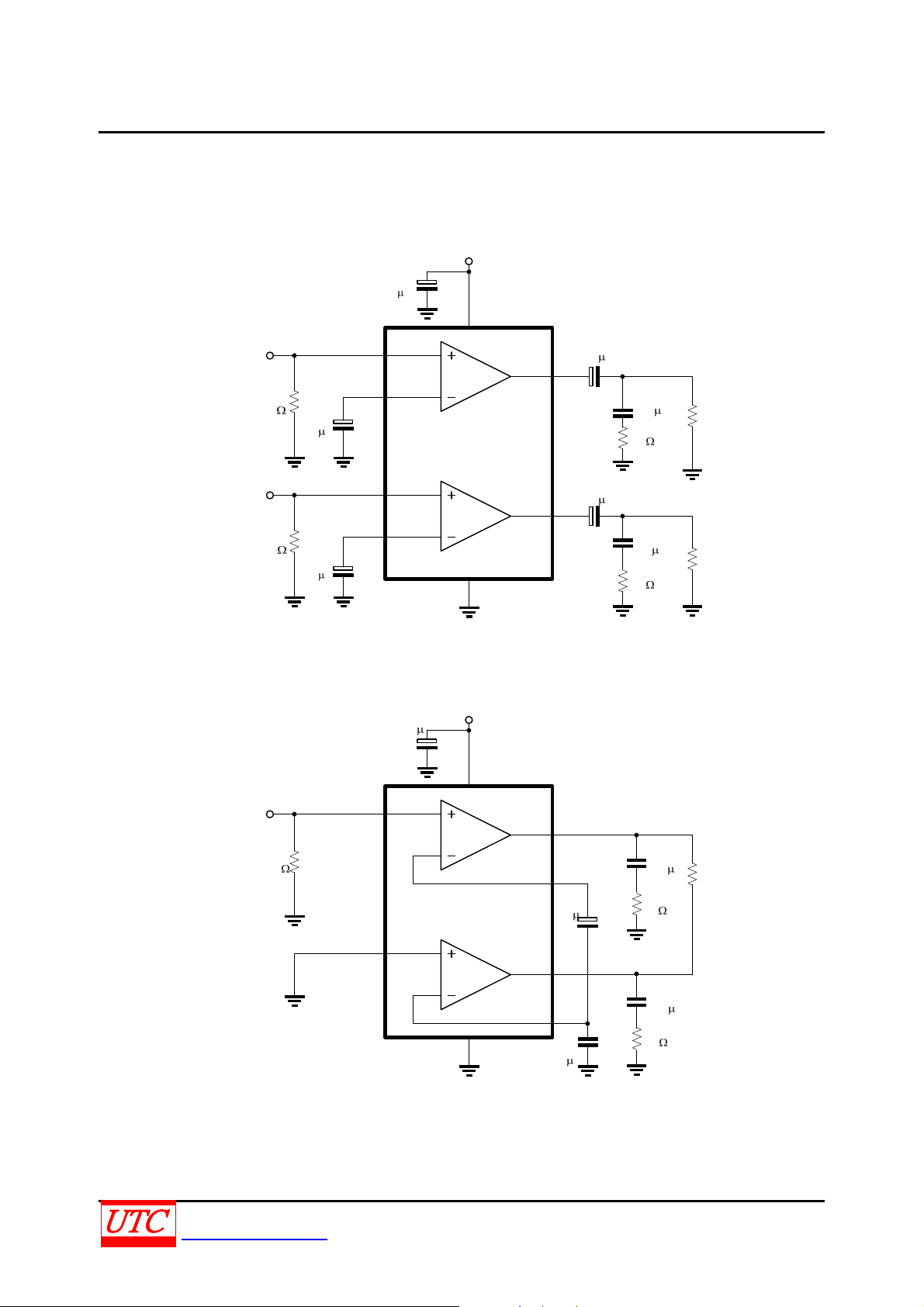
TEST CIRCUIT
STEREO
V
CC
C3
100
F
2
INPUT1
10k
R1
100
7
8
C1
F
C4
470
F
1
C6
0.1
F
R
R3
4.7
L
BRIDGE
INPUT2
INPUT1
10k
10k
R2
R1
100
C2
6
5
F
4
C5
470
3
F
C7
0.1
F
R
R4
4.7
L
V
C5
F
100
7
CC
2
1
C2
0.1
F
8
10
C1
R2
F
4.7
R
L
6
3
C3
0.1
5
4
C4
0.01
F
F
R3
4.7
UNISONIC TECHNOLOGIES CO., LTD 4 of 6
www.unisonic.com.tw QW-R107-006.G
TDA2822 LINEAR INTEGRATED CIRCUIT
SCHEMATIC DIAGRAM
UNISONIC TECHNOLOGIES CO., LTD 5 of 6
www.unisonic.com.tw QW-R107-006.G
TDA2822 LINEAR INTEGRATED CIRCUIT
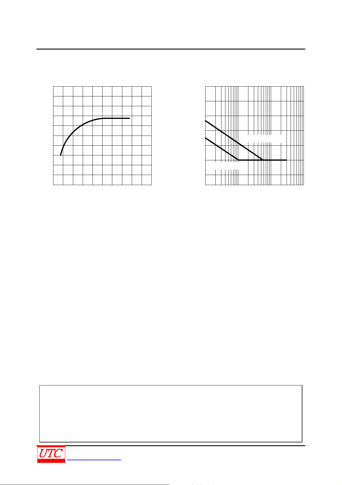
TYPICAL CHARACTERISTICS
8
0
6
4
Quescent Current (mA)
2
04 81216
Supply Voltage (V)
10
C1=C2=22μF
20
Ripple Rejection (dB)
30
C1=C2=100 μF
40
10 10030 300 1000 3000
Frequency (Hz)
UTC assumes no responsibility for equipment failures that result from using products at values that
exceed, even momentarily, rated values (such as maximum ratings, operating condition ranges, or
other parameters) listed in products specifications of any and all UTC products described or contained
herein. UTC products are not designed for use in life support appliances, devices or systems where
malf unction of these products can be reasonably expected to result in personal injury. Reproduction in
whole or in part is prohibited without the prior written consent of the copyright owner. The inform ation
presented in this document does not form part of any quotation or contract, is believ ed to be accurate
and reliable and may be changed without notice.
UNISONIC TECHNOLOGIES CO., LTD 6 of 6
www.unisonic.com.tw QW-R107-006.G

 Loading...