

UNISONIC TECHNOLOGIES CO., LTD
DTA114T
DIGITAL TRANSISTORS
(BUILT- IN BIAS RESISTORS)
FEATURES
* Built-in bias resistors that implies easy ON/OFF applications.
* The bias resistors are thin-film resistors with complete isolation to
allow positive input.
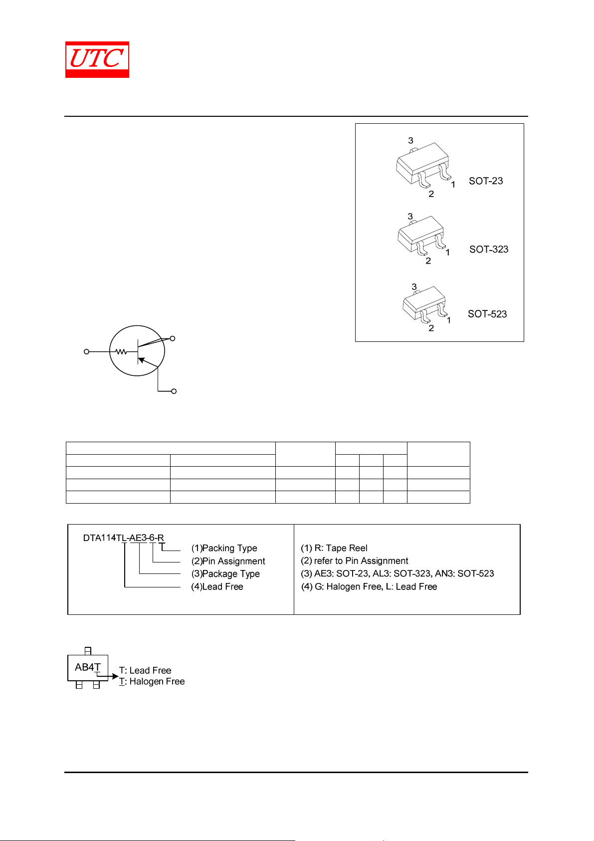
EQUIVALENT CIRCUIT
B
R1
C
E
PNP SILICON TRANSISTOR
ORDERING INFORMATION
Order Number
Lead Free Halogen Free 1 2 3
DTA114TL-AE3-6-R DTA114TG-AE3-6-R SOT-23 E B C Tape Reel
DTA114TL-AL3-6-R DTA114TG-AL3-6-R SOT-323 E B C Tape Reel
DTA114TL-AN3-6-R DTA114TG-AN3-6-R SOT-523 E B C Tape Reel
MARKING
Package
Pin Assignment
Packing
ofwww.unisonic.com.tw 1of 3
Copyright © 2011 Unisonic Technologies Co., Ltd QW-R206-061.C
DTA114T
)
PNP SILICON TRANSISTOR
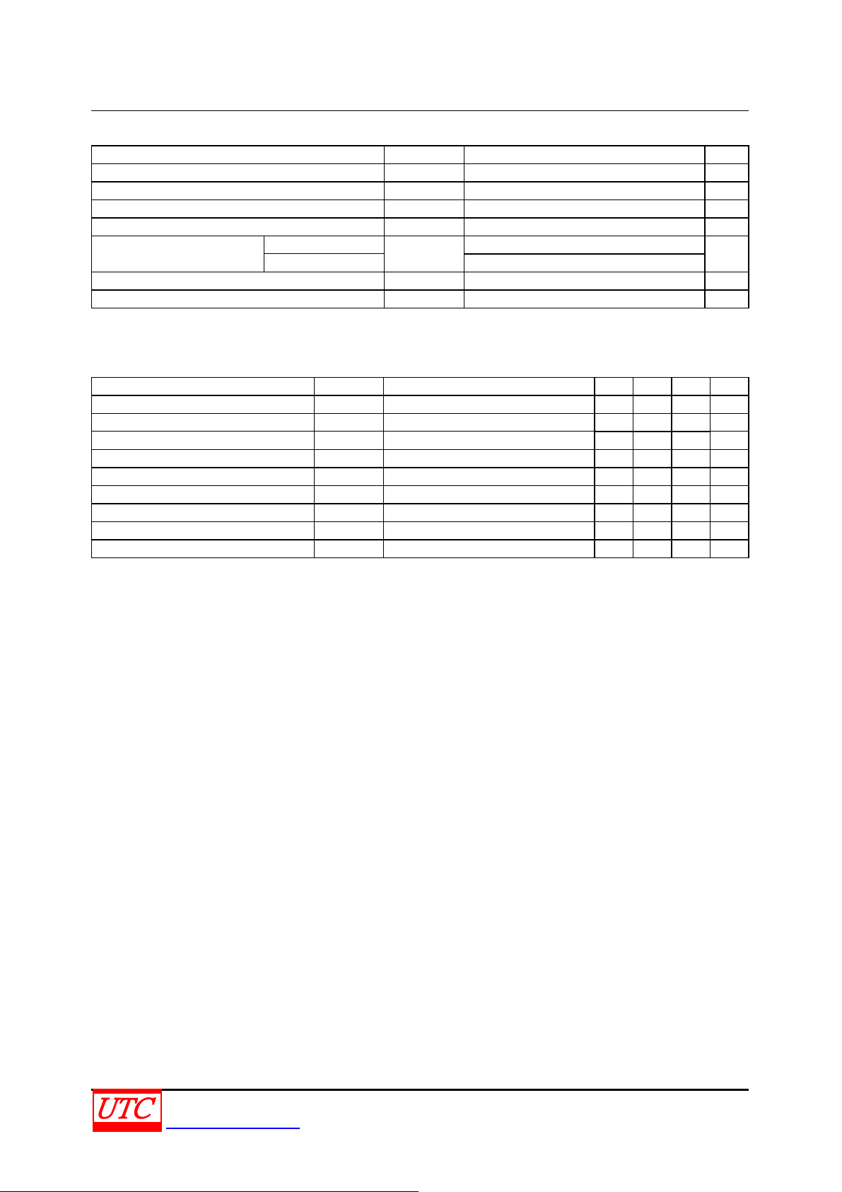
ABSOLUTE MAXIMUM RATINGS (T
= 25℃)
A
PARAMETER SYMBOL RATING UNIT
Collector-Base Voltage V
Collector-Emitter Voltage V
Emitter-Base Voltage V
-50 V
CBO
-50 V
CEO
-5 V
EBO
Collector Current IC -100 mA
Collector Power Dissipation
SOT-23
SOT-323/SOT-523 150
PC
200
mW
Junction Temperature TJ +150 ℃
Storage Temperature T
-55~+150 ℃
STG
Note Absolute maximum ratings are those values beyond which the device could be permanently damaged.
Absolute maximum ratings are stress ratings only and functional device operation is not implied.
ELECTRICAL CHARACTERISTICS (T
= 25℃, unless otherwise specified)
A
PARAMETER SYMBOL TEST CONDITIONS MIN TYP MAX UNIT
Collector-Base Breakdown Voltage BV
Collector-Emitter Breakdown Voltage BV
Emitter-Base Breakdown Voltage BV
Collector-Emitter Saturation Voltage V
Collector Cutoff Current I
Emitter Cutoff Current I
IC=-50μA -50 V
CBO
IC=-1mA -50 V
CEO
IE=-50μA -5 V
EBO
IC=-10mA, IB=-1mA -0.3 V
CE(SAT
VCB=-50V -0.5 μA
CBO
VEB=-4V -0.5 μA
EBO
DC Current Gain hFE VCE=-5V, IC=-1mA 100 250 600
Input Resistance R1 7 10 13 kΩ
Transition Frequency fT VCE=-10V, IE=5mA,f=100MHz (Note) 250 MHz
Note: Transition frequency of the device
UNISONIC TECHNOLOGIES CO., LTD 2 of 3
www.unisonic.com.tw QW-R206-061.C

DTA114T
■ TYPICAL CHARACTERISTICS
PNP SILICON TRANSISTOR
(mV)
FE
DC Current Gain, h
CE(SAT)
Collector Saturation Voltage, V
UTC assumes no responsibility for equipment failures that result from using products at values that
exceed, even m omentarily, rated values (such as maximum ratings, operating condition ranges, or
other parameters) listed in products specifications of any and all UTC products described or contained
herein. UTC products are not designed for use in life support appliances, devices or systems where
malfunction of these products can be reasonably expected to result in personal injury. Reproduction in
whole or in part is prohibited without the prior written consent of the copyright owner. The information
presented in this document does not form part of any quotation or contract, is believed to be accurate
and reliable and may be changed without notice.
UNISONIC TECHNOLOGIES CO., LTD 3 of 3
www.unisonic.com.tw QW-R206-061.C

 Loading...