

263B-CO-OEM
Carbon Monoxide Alarm
Product Introduction
This wireless carbon monoxide (CO) Alarm (product) monitors the levels
of CO gas and gives early warning when potentially dangerous levels
exist. It does not detect fire, smoke, or any other gas. If a dangerous
concentration of CO is detected by patented and field-proven
electrochemical sensor, an LED indicator illuminates and an internal
siren is activated in Temporal 4 pattern. The CO Alarm also transmits
an alarm signal to the control panel within 15 seconds of detecting
dangerous concentration of CO gas. The control panel activates its
internal siren and reports the alarm condition to the central monitoring
station (if the system is monitored). The CO Alarm also detects low
battery, wall tamper, and sensor end-of-life. These trouble codes are
transmitted to the control panel which reports the condition to the
central monitoring station. The alarm automatically reset when CO is
no longer detected.
This wireless CO Alarm is Listed and compliant with the ANSI/UL 2034
standard for CO Alarms. It is intended for residential indoor dwelling
unit applications and other areas approved by the authority having
jurisdiction (AHJ). It is not intended for use in industrial applications.
This wireless product works in conjunction with your wireless Control
Panel, providing a local indication. Refer to the panel installation
instructions for revision verification details. Please contact Technical
Support for any questions regarding compatibility.
About This Guide
This User Guide describes how to install, the operation and
maintenance of this product. The User Guide is organized as you intent
to use this product with step by step instructions.
Keep this document in a handy location and refer to it when you have
questions about this product and its functions and features. Reading
this guide is the only way to learn how to use your product wisely and
to know how to react in the event of an alarm.
Attention: Please take a few minutes to thoroughly read this
guide which should be saved for future reference and passed on to
any subsequent owner.
1. General Information
Congratulations on purchasing your Carbon Monoxide Alarm. This
product is designed to be used with a Control Panel as part of the Life
Safety signaling device. This product has a chemical CO sensor
capable of detecting CO gases in the event of dangerous CO gas
exposure.
WARNING: After seven years from initial power up, this alarm
will beep two times every 30 seconds to indicate that it is time to
replace the alarm. Replace the alarm immediately! It will not detect CO
in this condition.
To help identify the date to replace the alarm, an area has been
reserved on the side of the alarm. Write the “replace by” date (seven
years from power up) with a permanent marker in the area provided.
Parts List
One Carbon Monoxide Alarm
Three AA alkaline batteries
Mounting Plate
Mounting Screws and Anchors
User Guide
2. Mounting Guideline
This product is a member of a reliable, high-quality product family
using the latest technology available. Review the information in this
section to ensure you get the most out of the product.
Choosing an Installation Location
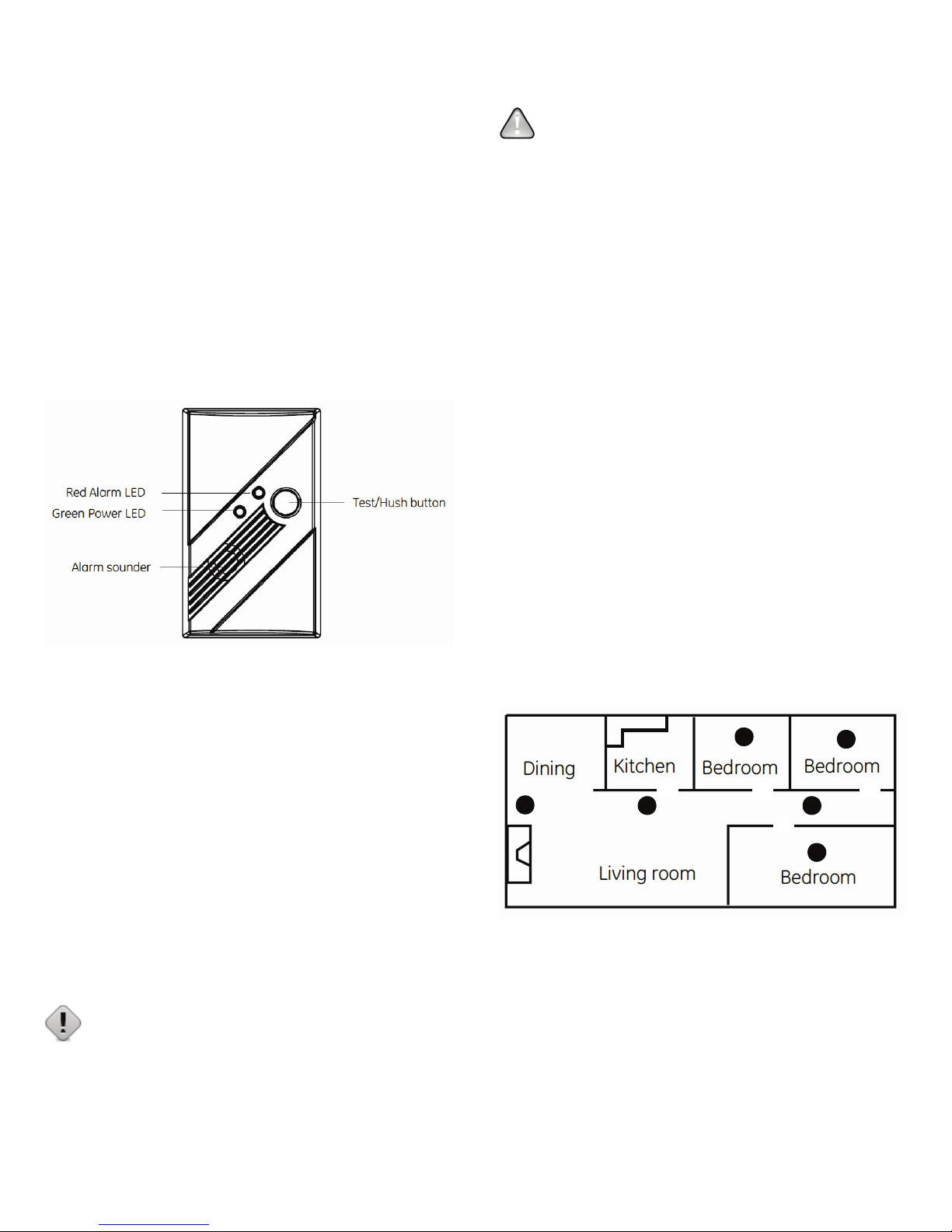
CO Alarms should be mounted in or near bedrooms and living areas.
We recommend that you install an alarm on each level of your home.
When choosing your installation locations, make sure you can hear the
alarm from all sleeping areas. If you install only one CO Alarm in your
home, install it near bedrooms, not in the basement or furnace room.
Place the alarm out of reach of children. Under no circumstances
should children be allowed to handle the CO Alarm.
Recommended locations
Locations to avoid
Improper location can affect the sensitive electronic components in this
alarm. To avoid causing damage to the unit, to provide optimum
performance, and to prevent unnecessary nuisance alarms:
o Do not install in kitchens, garages, or furnace rooms that may
expose the sensor to substances that could damage or
contaminate it.
o Do not install in areas where the temperature is colder than
40°F (4.4°C) or hotter than 100°F (37.8°C) such as crawl spaces,
attics, porches, and garages.
o Do not install within 5 ft. of heating or cooking appliances. (We
recommend 15 ft. to prevent nuisance alarms.)
UTC. All Rights Reserved. 1 P/N 0000000 – Rev. A – 06 Nov 12
o Do not install near vents, flues, chimneys, or any
forced/unforced air ventilation openings.
o Do not install on metal surfaces.
o Avoid mounting in areas with a large quantity of metal or
electrical wires.
o Do not install near ceiling fans, doors, windows, or areas
directly exposed to the weather.
o Do not install in dead air spaces, such as peaks of vaulted
ceilings or gabled roofs, where CO may not reach the sensor in
time to provide early warning.
o Do not install near deep-cell large batteries. Large batteries
have emissions that can cause the alarm to perform at less
than optimum performance.
o Do not obstruct the vents located on the alarm. Do not place the
alarm where drapes, furniture, or other objects block the flow of
air to the vents.
3. Mounting the Sensor
Note: Add the product to the Control Panel before physically mounting
the product in the desired location. This verifies RF performance prior to
permanently mounting the alarm. See “RF communication test”.
The CO Alarm can be wall mounted or ceiling mounted.
To mount the alarm:
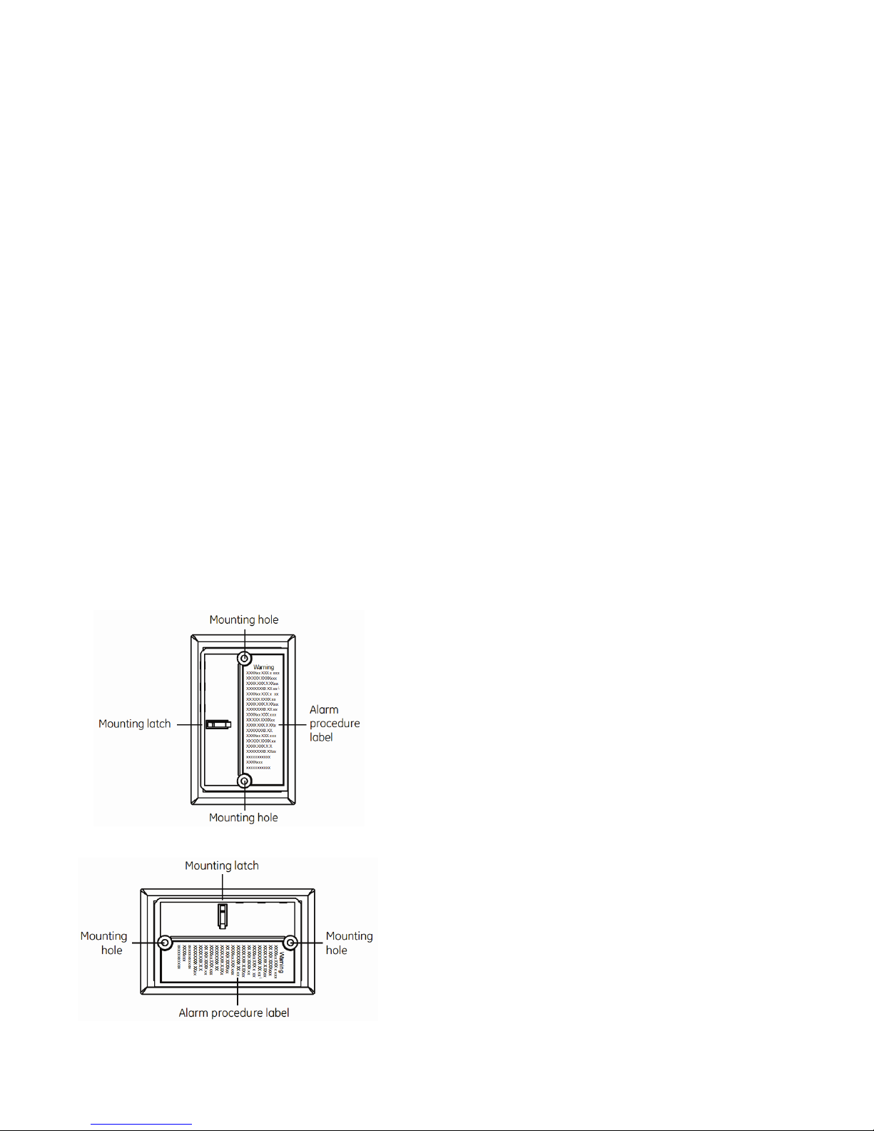
A. Slide the product body off of the mounting plate. Place the
mounting plate in the desired location, and mark the location of
the two mounting holes. Orient the mounting plate vertically or
horizontally as shown in the following figures.
Note: The product can also be directly mounted to a single gang box.
Vertical Mounting
Horizontal Mounting
drywall, drill a 3/16 in. hole and use the plastic anchors
provided.)
C. After the mounting plate is secured, slide the alarm over the
mounting plate (see Figure 4 on page 2).
Important labels provided
Two labels have been provided that have important information on
what to do in case of an alarm. Add the phone number of your
emergency service provider in the space provided. Place one label next
to the alarm after it is mounted, and one label near a fresh air source
such as a door or window.
4. Basic Operations
This product is equipped with an intuitive normal mode operation.
Since the batteries are pre-installed, remove the battery pull tab to turn
ON power. The product shall search for a networked control panel to
pair with. During this time, Search Mode, the RF wireless module
transmits every ~ 5-seconds. Not pairing or enrolling into a control
panel within minutes of initial power up, places a large drain the
batteries. Failure to complete pairing results in dead batteries after 2-3
days time passes.
Normal Mode Operation
o In normal operation, the green Power LED flashes once every 30
seconds.
o In alarm mode, the red Alarm LED flashes with four quick
beeps, 5-seconds silence and repeat.
o In trouble or maintenance mode, the red Alarm LED flashes
once every 30 seconds with one audible chirp.
o In low battery mode, the red Alarm LED flashes once every 60
seconds with one quick beep until the batteries are replaced.
Press the Test/Hush button to silence the audible chirp for
between 8-11 hours.
Note: the modes can be viewed from the Control Panel.
Silence the Alarm
Press the Test/Hush button to silence the sounder during an alarm.
After a few minutes, the sounder and alarm resume if dangerous CO
gas levels are still present.
5. Installing / Replacing Battery
This product comes with three battery preinstalled. When you need to
replace the battery, use the following procedure.
Note: Place the control panel into sensor test mode prior to replacing
the batteries. If the control panel is not in sensor test mode during
battery replacement, an alarm/tamper condition may be indicated.
A. Slide the product body off of the mounting plate.
B. If replacing batteries, remove the old batteries and properly
dispose of them as recommended by the battery manufacturer.
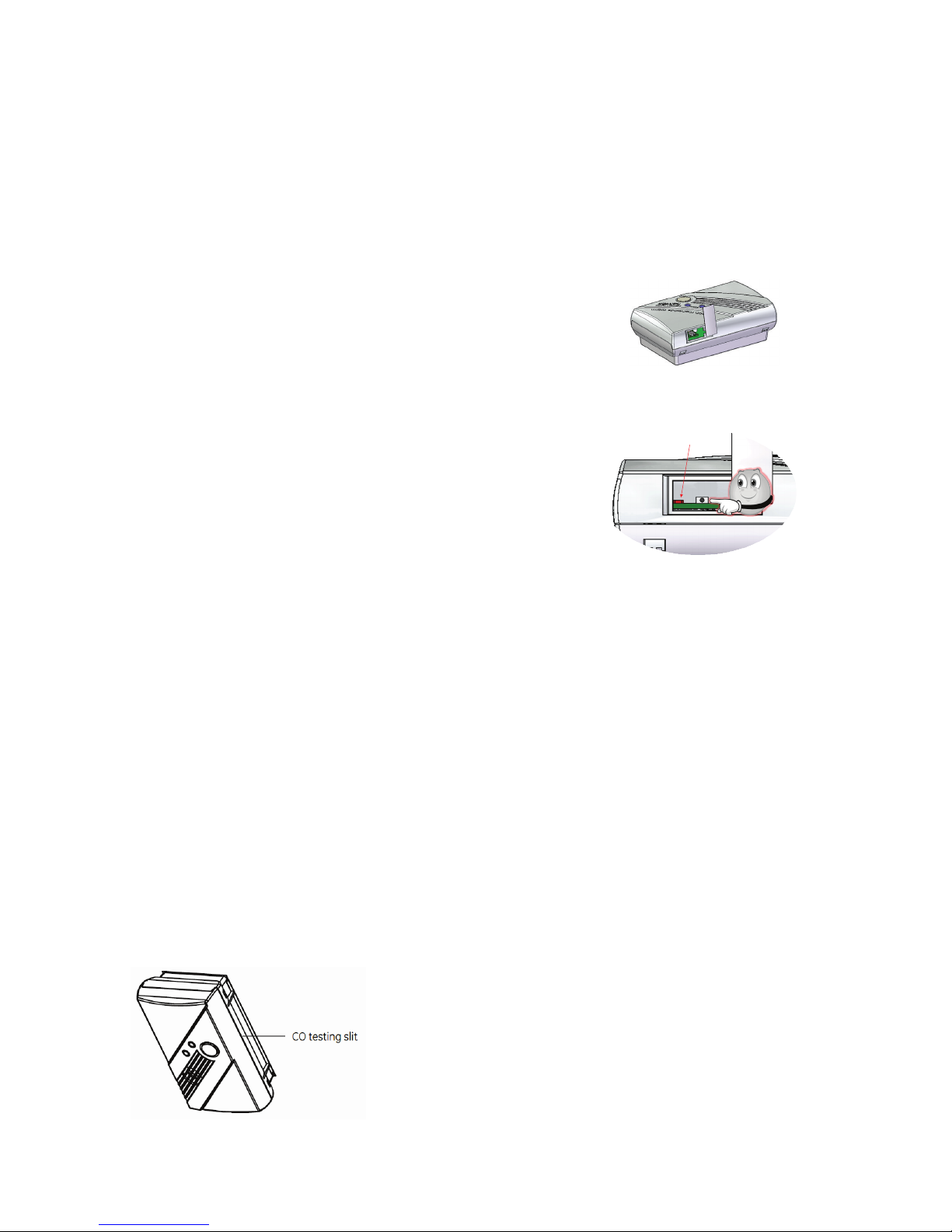
C. Install the new batteries. Note the polarity illustration in the
battery compartment (see Figure 3 below).
B. Insert the two screws provided and secure the mounting plate
to the wall or ceiling surface. (If mounting in plasterboard or
UTC. All Rights Reserved. 2 P/N 0000000 – Rev. A – 06 Nov 12

D. Slide the product body back onto the mounting plate.
Note: The mounting plate will not close if all three batteries are not
installed.
Sliding the alarm on the mounting plate
E. Perform a sensor/RF test with the control panel. See “RF
communication test”.
When replacing the batteries, use one of the following approved
brands:
o Duracell MN1500 or MX1500
o Energizer E91
Note: Use of a different battery may have a detrimental effect on the
alarm operation. Constant exposures to high or low humidity may
reduce battery life.
After installing or changing the batteries, reinstall your product. Test
your product by checking the green Power LED flashes once every 30
seconds and using the Test/Hush button to create an alarm condition.
6. Adding to the Control Panel
Each product is programmed with a unique ID when manufactured.
The unique ID is enrolled into the control panel at the time of
installation, allowing the detector to communicate with that specific
control panel.
A. Log in to the Settings app with an Installer code.
B. In the Settings menu, tap Sensors & Zones > Add a Sensor/Zone.
C. Place the product in Search mode and prepare it to be added to
the control panel (refer to the installation documentation for your
sensors). Available sensors meet the following requirements:
o Defaulted.
o Not currently paired with another control panel device.
o Currently in Search mode.
D. At the Locating Wireless Sensors screen, tap Next. A Done button
appears on the screen and the control panel searches for sensors
that are available to be added. As sensors are found, a grayed
icon appears for that sensor.
E. Fault each found sensor to pair it to the control panel. The icon for
each sensor is undarkened as it is faulted and the control panel
beeps. The sensor is paired to the control panel.
F. When all the sensors are found and paired, tap Stop. Any located
sensors that were not paired are released by the control panel
and can be added later. The Wireless Sensors Located screen
shows the number of wireless sensors found and paired.
G. Tap Next. The Configure Wireless Sensors screen shows icons of
the sensors that were found and paired.
H. Touch each sensor icon to configure the corresponding product.
The Add Sensor/Zone Modify screen appears.
I. To change the product Icon (if multiple options are available), tap
the currently selected value.
J. Tap Next. The Add Sensor/Zone Modify screen appears.
K. To modify a text field on the control panel, tap the field, use the
onscreen keyboard to enter your changes, and tap Done to save
your changes.
L. When all sensors are configured properly, tap Next in the
Configure Wireless Sensors screen.
M. If all of the sensors have not been configured, the Modify screen
appears for each sensor to let you review its details. Change the
details as needed or tap Next to cycle through all the sensors. The
sensors are marked as configured.
7. Testing the Product
This product may be tested during install or at anytime. It is
recommended the product be tested in place annually. This product is
sealed. The cover is not removable.
WARNING: The control panel must be placed into sensor test
mode while conducting any tests. Placing the control panel into sensor
test mode for all testing helps to protect against false alarms and
unintentional central station reporting.
Due to the loudness of the alarm, we suggest that you place your
fingers over the sounder vent while testing your alarm.
Caution: Continuous exposure to the high sound level of this
alarm over an extended period of time may cause hearing loss.
This product provides three test modes:
o Normal CO Alarm Test. Conducts an internal self test and tests
the sounder.
o RF Communication Test. Tests the communication path with
the control panel.
o CO Alarm Functional Gas Test. Tests the functional operation
of the CO sensing element.
Normal CO Alarm Test
A. Wait at least 10 minutes after installation to test the CO Alarm.
B. Make sure the green Power LED is flashing for normal
operation.
C. Set the control panel to sensor test mode.
D. Press and hold the Test/Hush button until the unit beeps once
(approximately 1 second), and then release the button. If the unit
UTC. All Rights Reserved. 3 P/N 0000000 – Rev. A – 06 Nov 12
is operating properly, you will hear four quick beeps, followed
LED
by 5 seconds of silence, followed by four quick beeps.
E. At the control panel, exit sensor test mode.
This test mode does not test communication with the control panel. You
will receive a “Sensor Test Fail or Abort” message when the control
panel exits sensor test mode.
RF Communication Test
This section provides general guidelines for testing the product with the
control panel. For complete testing details, refer to the specific control
panel documentation.
A. Be sure the product is normal operation with the green Power
LED is flashing once every 30 seconds.
B. Wait at least 10 minutes after installation to test.
C. Set the control panel to sensor test mode to prevent an alarm
signal from being sent to the central-monitoring station if you
have a monitored system.
D. To generate a test alarm, press and hold Test/Hush button for ~
5 seconds and then release. If the product is operating properly,
you will hear four quick beeps.
An alarm message is sent to the
control panel. To generate a tamper alarm, remove the product
from the mounting plate. A tamper alarm message is sent to
the control panel.
E. The control panel beeps and shows the number of RF packets
received.
F. At the panel, exit sensor test mode.
CO Alarm Functional Gas Test
This step should only be performed by a qualified service technician.
Consult the most recent version of NFPA 720 for more information
regarding the requirement for functional testing of CO alarms and/or
your Local Authority Having Jurisdiction (AHJ).
A canned CO testing agent must be used for the CO functional gas test.
A. Wait at least 10 minutes after installation to test the CO Alarm.
B. Make sure the green Power LED is flashing for normal
operation.
C. Set the control panel to sensor test mode.
D. Press and hold the Test/Hush button until the unit beeps
three times (approximately 10 seconds), and then release the
button. The unit will enter the functional gas test mode. The
Power LED will blink once per second while in functional test
mode.
E. Apply UL approved CO test agent to the slit as shown in
Figure 7 below. When CO is detected, the unit will activate a
CO Alarm. The unit will send RF test packets to the control
panel when the CO Alarm is activated.
CO Testing Slit
F. The control panel will beep and display the number of RF
packets received.
G. At the control panel, exit sensor test mode.
H. Exit functional gas test mode:
I. Press and release the Test/Hush button; or A 2 minute timeout
will automatically cause the CO to return to normal operating
mode.
8. Defaulting the Detector
This step should only be performed by a qualified service technician.
A. Remove the product form the mounting plate.
B. Remove the three batteries.
C. Remove the access door on product’s top cover.
D. Press the enrollment switch in the RF circuit inside the product
and hold until you replace the batteries.
E. Replace the batteries while still pressing the enrollment switch
then release the switch. The RF Module LED flashes three times
to signal the detector is not paired with a control panel.
F. Remove the batteries and install the top cover.
9. Viewing Zone Event History
To view event history:
A. Tap the Security widget on the Home screen.
B. Tap the History tab. The Zone Event History shows the event
history.
10. Disabling Zones
The system can bypass a zone, so the zone is not monitored when the
system is armed. This is useful when a sensor is being repaired. You
can only change the Bypass state of a zone when the system is
disarmed.
The system continues to log the activity of bypassed zones in the Event
History (see “View Zone Event History,” above).
To bypass a zone:
A. With the system disarmed, tap the Security app on the Home
screen.
B. Tap the Turn Zone Off button for the smoke alarm. The Turn Zone
Off button changes to Turn Zone On.
C. When the system is disarmed, the Security Status header shows
that some zones have been bypassed.
UTC. All Rights Reserved. 4 P/N 0000000 – Rev. A – 06 Nov 12

11. Deleting the Product from the Control Panel
Deleting a sensor from the premises removes it from being monitored
by the customer’s system. This is not the same as disabling (bypassing)
a sensor. You should delete a sensor only:
o If the product is being removed from the premises
o To reset the product to factory default settings by deleting the
product and re-adding it immediately.
To delete a product from the system:
A. Contact Customer Care to obtain the Premise Passphrase for
the current customer account.
B. Perform steps A through D in Step 6, “Adding to the Control
Panel.”
C. When the Technician Settings menu appears, select Sensors
& Zones > Delete a Sensor/Zone. The Premise Passphrase
keyboard appears.
D. Enter the Premise Passphrase and click Done. The currently
installed sensors/security zones appear.
E. Tap the zone you want to delete and follow the instructions
provided by the Control Panel to delete the sensor and
security zone from the current system.
12. Maintenance
This product is design for a long service life of 10-years. Even though
the control panel indicates when to service this product, several annual
and random/as required checks are recommended.
Weekly - CO Alarm Test once a week
Annual - CO Alarm Functional Gas Test
Random - visual check for green Power LED flashing every 30
seconds
- Wireless Signal Strength
The control panel indications are Trouble and Low Battery.
Trouble - the product has an internal fault, which requires
technical service.
Low Battery - batteries are low and must be replaced to maintain
proper operation.
In General
To keep your alarm in good working order:
o Vacuum the product cover once a month to remove
accumulated dust.
o Never use detergents or solvents to clean the product.
Chemicals can permanently damage or temporarily
contaminate the sensor.
o Avoid spraying air fresheners, hair spray, paint, or other
aerosols near the product.
o Do not paint the product. Paint will seal the vents and interfere
with proper sensor operation.
o Move the product to a remote location, to prevent possible
damage or contamination of the sensor, prior to performing
any of the following:
o Staining or stripping floors or furniture, painting or wall-
papering.
o Using aerosols or adhesives.
WARNING: Reinstall the product as soon as possible to assure
continuous protection.
o The following is a list of substances that at high levels can
damage the CO sensor or cause temporary readings that are
not CO readings:
− Ethylene, ethanol, alcohol, iso-propanol, benzene,
toluene, ethyl acetate, hydrogen, hydrogen sulfide, and
sulfur dioxide.
− Also most aerosol sprays, alcohol-based products,
paint, thinner, solvent, adhesive, hair spray, after shave,
perfume, auto exhaust (cold start), and some cleaning
agents.
Wireless Signal Strength
After adding the product to the control panel and installing this product,
test the signal strength between the control panel and its added
sensors/security zones:
A. Be sure steps A through D in Section 6, “Adding to the Control
Panel” have been performed.
B. When the Technician Settings menu appears, select Sensors &
Zones > Sensor Diagnostics.
C. When the currently installed sensors/ security zones appear,
tap the zone you want to test for connectivity and follow the
instructions from the control panel.
The Sensor Diagnostic for <Security Zone name> appears as the
system detects the current signal strength between the selected sensor
and the control panel.
Trouble
Refer to Section 13 for trouble shooting guidance.
Low Battery
Replace the batteries per Section 5 - Installing / Replacing Battery.
13. Troubleshooting
Product does not power up properly or reports low battery
o Be sure the battery is fully seated within the battery
compartment and the polarity is correct.
o Check the battery voltage (1.5 VDC nominal).
Control Panel does not respond
o Use a wireless RF Sniffer to confirm that the product is sending
messages for activation.
o Be sure the product is enrolled into the control panel properly.
o Be sure you are using a compatible control panel.
Tamper condition does not restore
o Be sure the product is installed properly onto the mounting
plate and the mounting plate has a magnet.
o Be sure there are no trouble indications at the detector.
o Be sure you are using a compatible control panel.
If a tamper alarm occurs
o Be sure you are using a compatible control panel.
o Be sure the control panel is in sensor test mode during sensor
testing.
Alarm/open condition does not restore
o Be sure the smoke or heat has cleared at the product.
o Be sure you are using a compatible control panel.
UTC. All Rights Reserved. 5 P/N 0000000 – Rev. A – 06 Nov 12

Operation Characteristics
more convenient time to replace the
unit has malfunctioned. Replace
unit has malfunctioned. Replace
plate. If condition continues, unit has
35 µA (typically)
Normal operation
Carbon monoxide alarm
Low battery / low battery
hush
Alarm end-of-life indicator
Trouble/service alarm
Error condition
Test mode
Tamper
LED Display Alarm Sound Units Status
Green Power LED
flashes every 30
seconds.
Red Alarm LED flashes
with beeps.
Red Alarm LED flashes
every 60 seconds.
Red Alarm LED flashes
two times every 30
seconds.
Red Alarm LED flashes
every 30 seconds.
Red Alarm LED
constantly on.
Red Alarm LED flashes
with beeps.
Red Alarm LED flashes
every 30 seconds.
14. Specifications
Compatible panels -
Power Three AA battery
1.5 VDC Alkaline
Battery type
Standby Current
Battery Life 5 years (typically)
Sensor Life 10 years
Alarm Response Time
Audible alarm 85 dBa @ 10’ (3M) temporal 4
Low Battery Beep 1 every 60 seconds.
RF Wireless Frequency 2.4 GHz
Weight w/battery 0.20 lbs / 0.09 kg
Dimensions 5.6" x 2.4" (14.2cm x 6.1cm)
Storage temperature -4 to 140°F (-20 to 60°C)
Operating environment 40 to 100°F (4.4 to 37.8°C)
Relative Humidity 10 to 95% non-condensing
Duracell MN 1500 or MX 1500,
Energizer E91
70 PPM = 60-240 min.
150 PPM = 10-50 min.
400 PPM = 4-15 min.
None.
Four quick beeps, 5
seconds silence,
repeating.
One quick beep every
60 seconds.
Two quick beeps
every 30 seconds.
One quick beep every
30 seconds.
Constant alarm.
Four quick beeps, 5
seconds silence,
repeated once.
One quick beep every
30 seconds.
Normal DC operation
(sensing no CO) and
with good batteries.
Alarm condition.
Dangerous
concentrations of CO
detected.
Batteries need to be
replaced.
End of CO Alarm life.
Unit is in trouble
condition.
Very low battery or
unit malfunction.
Normal operation
when Test/Hush
button is pressed.
Unit is in tamper
condition.
Control Panel
Status
Normal operating
condition.
Alarm condition. None.
Trouble condition,
trouble beeps every 60
seconds.
Trouble condition,
trouble beeps every 60
seconds.
Trouble condition,
trouble beeps every 60
seconds.
Trouble condition,
trouble beeps every 60
seconds.
Sensor test mode
Trouble condition,
trouble beeps every 60
seconds.
None.
Replace all three AA batteries.
Press Test/Hush button and release. This
will silence the low battery audible chirp
between 8 and 11 hours allowing for a
batteries.
Press the Test/Hush button and release.
This will silence the end-of-life signal for
up to three days. After three days, the unit
will resume end-of-life chirps. Hush mode
will silence the alarm ten times or up to 30
days. After 30 days, the unit can no longer
be hushed. Replace the CO Alarm
immediately. The unit will not respond to
CO.
Replace batteries. If condition continues,
immediately. Unit will not respond to CO.
Replace batteries. If condition continues,
immediately. Unit will not respond to CO.
CO not detected. Alarm for test purposes
only.
Place alarm body back onto mounting
malfunctioned. Replace immediately.
Recommendation
15. Regulatory Information
Manufacturer: UTC Fire & Security
WEEE Directive
2002/96/EC (WEEE directive): Products marked with this symbol cannot
be disposed of as unsorted municipal waste in the
European Union. For proper recycling, return this product to
your local supplier upon the purchase of equivalent new
equipment, or dispose of it at designated collection points.
For more information see: www.recyclethis.info.
RoHs Directive
2002/95/EC RoHS Compliant. Hereby, UTC Fire & Security declares that
this product does not contain lead, mercury, cadmium, hexavalent
chromium, polybrominated biphenyls (PBB) or polybrominated
depheny ethers (PBDE) in more than the percentage specified by EU
directive 2002/95/EC, except exemptions stated in EU directive
2002/95/EC annex.
UL Rating
ANSI/UL 2034 Recognized
FCC Compliance
FCC ID: QPY-263XCO-Z
IC: 8303B-263XCO-Z
UTC. All Rights Reserved. 6 P/N 0000000 – Rev. A – 06 Nov 12

The device complies with part 15 of the FCC Rules as well as Industry
Canada Rules and Regulations license-exempt RSS standard(s).
Operation is subject to the following two conditions: (1) This device may
not cause harmful interference, and (2) this device must accept any
interference received, including interference that may cause undesired
operation.
Conformité Réglementaire
Ce dispositif est conforme à la réglementation de la IC et (Partie 15) de
la FCC. Son fonctionnement est soumis à deux conditions : (1) ce
dispositif ne doit pas causer d’interférences nuisibles, et (2) ce dispositif
doit accepter toute interférence reçue, y compris les interférences
pouvant entraîner des conditions de fonctionnement indésirables.
WARNING: Changes to Section 15 – Regulatory Information is
strictly prohibited. Any changes or modification made to the product
without the permission of the manufacturer could void the user’s
authority to use this product.
16. Information about Carbon Monoxide
Carbon monoxide is a colorless, odorless, and tasteless poison gas
that can be fatal when inhaled. CO inhibits the blood’s capacity to carry
oxygen.
Periodically review this alarm manual and discuss your CO Alarm
emergency procedure with all members of your family. Never ignore a
CO Alarm. A true alarm is an indication of potentially dangerous levels
of CO. CO Alarms are designed to alert you to the presence of CO
before an emergency - before most people would experience
symptoms of CO poisoning, giving you time to resolve the problem
calmly.
Determine if anyone in the household is experiencing symptoms of CO
poisoning. Many cases of reported CO poisoning indicate that while
victims are aware they are not well, they become so disoriented they
are unable to save themselves either by exiting the building or calling
for assistance. Also, young children and household pets may be the
first affected. You should take extra precautions to protect high-risk
persons from CO exposure because they may experience ill effects
from CO at levels that would not ordinarily affect a healthy adult.
Symptoms of CO poisoning
The following common symptoms are related to CO poisoning and
should be discussed with ALL members of the household:
o Mild exposure = Slight headache, nausea, vomiting, fatigue
(often described as “flu-like” symptoms).
o Medium exposure = Severe throbbing headache, drowsiness,
confusion, fast heart rate.
o Extreme exposure = Unconsciousness, convulsions, cardio-
respiratory failure, death.
If you experience even mild symptoms of CO poisoning, consult your
doctor immediately.
Conditions that can produce carbon monoxide
o Excessive spillage or reverse venting of fuel burning appliances
caused by:
o Outdoor ambient conditions such as wind direction and/or
velocity, including high gusts of wind; heavy air in the vent pipes
(cold/humid air with extended periods between cycles).
o Negative pressure differential resulting from the use of exhaust
fans.
o Simultaneous operation of several fuel burning appliances
competing for limited internal air.
o Vent pipe connection vibrating loose from clothes dryers,
furnaces, or water heaters.
o Obstructions in or unconventional vent pipe designs which
amplify the above situations.
o Extended operation of unvented fuel burning devices (range,
oven, fireplace, etc.).
o Temperature inversions which can trap exhaust gasses near
the ground.
o Car idling in an open or closed attached garage, or near a
home.
What CO alarms can and cannot do
CO Alarms provide early warning of the presence of CO, usually before
a healthy adult would experience symptoms. This early warning is
possible however, only if your CO Alarm is located, installed, and
maintained as described in this manual.
Because carbon monoxide is a cumulative poison, long-term
exposures to low levels may cause symptoms, as well as short-term
exposures to high levels. This unit has a time-weighted alarm; the
higher the level of CO present, the sooner the alarm will be triggered.
This CO Alarm can only warn you of the presence of CO. It does not
prevent CO from occurring, nor can it solve an existing CO problem. If
your unit has alarmed and you’ve provided ventilation by leaving your
windows and doors open, the CO buildup may have dissipated by the
time help responds. Although your problem may appear to be
temporarily solved, it is crucial that the source of the CO is determined
and that the appropriate repairs are made.
CO Alarms have limitation. Like any other electronic device, CO Alarms
are not fool-proof. CO Alarms have a limited operational life. You must
test your CO alarm weekly, because it could fail to operate at any time.
If your CO Alarm fails to test properly, or if its self-diagnostic test reveals
a malfunction, immediately have the unit replaced. This alarm will not
monitor CO levels while in a trouble condition.
CO Alarm can only sense CO that reaches the unit’s sensor. It is
possible that CO may be present in other areas without reaching the
alarm. The rate and ability with which CO reaches the alarm may be
affected by:
o Doors or other obstructions.
o Fresh air from a vent, an open window, or other source.
o CO being present on one level of the home and not reaching a
CO Alarm installed on a different level. (For example, CO in the
basement may not reach an alarm on the second level, near
the bedrooms).
For these reasons, we recommend you provide complete coverage by
placing a CO Alarm on every level of the home.
CO Alarms should not be used to detect the presence of natural gas
(methane), propane, butane, or other combustible fuels.
Instruct children never to touch or otherwise interfere with the alarm.
Warn children of the dangers of CO poisoning.
UTC. All Rights Reserved. 7 P/N 0000000 – Rev. A – 06 Nov 12

Important warning statements
This product is manufactured by Kidde Safety, a UTC Fire and Security
Company, 1016 Corporate Park Drive, Mebane, NC 27302.
This carbon monoxide alarm is designed to detect carbon monoxide
from ANY source of combustion. It is NOT designed to detect smoke,
fire, or any other gas.
WARNING: Carbon monoxide alarms are not smoke alarms.
This carbon monoxide alarm is not a substitute for installing and
maintaining an appropriate number of smoke alarms in your home.
This CO alarm will not sense smoke, fire, or any poisonous gas other
than carbon monoxide even though carbon monoxide can be
generated by fire. For this reason you must install smoke alarms to
provide early warning of fire and to protect you and your family from
fire and its related hazards.
Caution: This alarm will only indicate the presence of carbon
monoxide at the sensor. Carbon monoxide may be present in other
areas.
WARNING: This product is intended for use in ordinary indoor
locations of family living units. It is not designed to measure
compliance with Occupational Safety and Health Administration
(OSHA), commercial, or industrial standards. It is not suitable for
installation in hazardous locations as defined in the National Electric
Code. The installation of this device should not be used as a substitute
for proper installation, use and maintenance of fuel burning
appliances, including appropriate ventilation and exhaust systems. It
does not prevent CO from occurring, nor can it solve an existing CO
problem.
WARNING: This device is designed to protect individuals from
acute effects of carbon monoxide exposure. It may not fully safeguard
individuals with specific medical conditions. If in doubt, consult a
medical practitioner. Individuals with medical problems may consider
using warning devices which provide audible and visual signals for
carbon monoxide concentrations under 30 PPM.
This carbon monoxide alarm requires a continuous supply of electrical
power - it will not work without power.
This alarm has not been investigated for carbon monoxide detection
below 70 PPM.
Limited Warranty
Kidde is a brand of UTC Fire & Security. The manufacturer warrants this
product (except batteries) to be free from defects in material and
workmanship under conditions of normal use for a term of 3 years
from the date of manufacture.
During the warranty period, if a UTC Fire & Security product or any of its
components becomes defective, it will be repaired or replaced without
charge.
Out-of-warranty units will be repaired at the discretion of the
manufacturer or, if not, a card will be forwarded to the customer
suggesting a replacement unit and the cost of that unit.
This warranty does not apply to units which have been subject to
abuse,
misuse, negligence or accident, or to which any modifications,
alterations or repairs have been made or attempted.
This warranty is extended only to the original purchaser of the smoke
alarm and may be enforced only by such person. During the warranty
period, if the alarm or any warranted components thereof becomes
defective, it will be replaced or repaired without charge at the
manufacturer’s discretion if returned in accordance with the following
instructions:
Obtain a Return Authorization Number by calling the number below,
then carefully pack it in a well padded and insulated carton and return,
postal charges prepaid to:
Return units to: UTC – Climate, Controls & Security
325 N Main St
Pittsfield, ME 04967
Phone: 1-207-487-3104
A note should be included advising the nature of the malfunction. Care
must be exercised in the proper packing of alarms returned under this
warranty as UTC Fire & Security will not be responsible for warranty
repairs to equipment damaged because of improper packing.
The above warranty is in lieu of all other express warranties, and
implied warranties of merchantability and fitness for a particular
purpose are limited in duration for a period of THREE years from the
date of manufacture. Under no circumstances shall manufacturer be
liable to the purchaser or any other person for incidental or
consequential damages of any nature, including without limitation
damages for personal injury or damages to property, and however
occasioned, whether alleged as resulting from breach of warranty by
manufacturer, the negligence of manufacturer or otherwise.
Manufacturer’s liability will in no event exceed the purchase price of the
product. Some states do not allow limitations on how long an implied
warranty lasts, or the exclusion or limitation of incidental or
consequential damages, so the above limitations and exclusions may
not apply to you. Unless a longer period is required by applicable law,
any action against manufacturer in
connection with this smoke alarm must be commenced within one
year after the cause of action has occurred.
No agent, employee or representative of the Manufacturer nor any
other person is authorized to modify this warranty in any respect.
Repair or replacement as stated above is the exclusive remedy of the
purchase hereunder. This warranty gives you specific legal rights and
you also have other rights which vary from state to state.
End of document
UTC. All Rights Reserved. 8 P/N 0000000 – Rev. A – 06 Nov 12
 Loading...