

Page 1
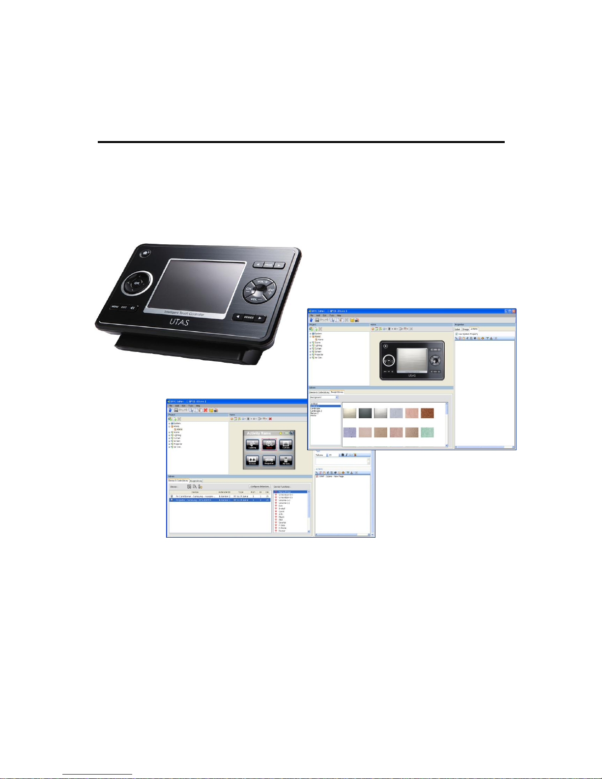
UIPC Editor User Manual
Intelligent Digital Controller UX3500
© 2010 UTAS Inc.
UTAS Inc provides information contained in this Manual ‘as is’ without warranties, and assumes no responsibility for any
inaccuracies, errors or omissions that may appear in this information. UTAS Inc specifically disclaims any implied
warranties of merchantability or fitness for any particular purpose. In no event will UTAS Inc be liable to any person for any
direct, indirect, special or other consequential damages arising from the use of any information contained herein. This
Manual is subject to change without prior notice. All proprietary information contained herein are protected under copyright.
This Manual should not be copied, translated or reproduced in whole or in part without prior written consent of UTAS Inc.
UTAS
www.utas.co.kr
Page 2

I. Program Installation
1. Installation of UIPC Editor Program ° ° ° ° ° ° ° ° ° ° °
2. Installation of MS Active Sync ° ° ° ° ° ° ° ° ° ° ° ° ° ° ° ° °
3. Setup for Window Vista Users ° ° ° ° ° ° ° ° ° ° ° ° ° ° ° °
II. About Program
1. UIPC Editor Configuration° ° ° ° ° ° ° ° ° ° ° ° ° ° ° ° ° ° ° ° ° ° °
2. Menu & Icon ° ° ° ° ° ° ° ° ° ° ° ° ° ° ° ° ° ° ° ° ° ° ° ° ° ° ° ° ° ° ° ° ° °
3. Project ° ° ° ° ° ° ° ° ° ° ° ° ° ° ° ° ° ° ° ° ° ° ° ° ° ° ° ° ° ° ° ° ° ° ° ° ° ° ° ° ° °
4. External Buttons/ LCD Touch Panel ° ° ° ° ° ° ° ° ° ° ° °
5. Properties (Buttons) ° ° ° ° ° ° ° ° ° ° ° ° ° ° ° ° ° ° ° ° ° ° ° ° ° ° °
6. Library ° ° ° ° ° ° ° ° ° ° ° ° ° ° ° ° ° ° ° ° ° ° ° ° ° ° ° ° ° ° ° ° ° ° ° ° ° ° ° ° ° °
7. Database Management° ° ° ° ° ° ° ° ° ° ° ° ° ° ° ° ° ° ° ° ° ° ° ° °
III. To Make New Project
1. To configure Page Screen ° ° ° ° ° ° ° ° ° ° ° ° ° ° ° ° ° ° ° ° ° ° ° ° °
2. To setup Button actions° ° ° ° ° ° ° ° ° ° ° ° ° ° ° ° °° ° ° ° ° ° °
IV. Test & Transmission ° ° ° ° ° ° ° ° ° ° ° ° ° ° ° ° ° ° ° ° °
V. Examples of Screen Configuration ° °
CONTENTS
3
5
8
9
10
12
13
14
15
19
24
27
32
33
Page 3
3
UIPC Editor is a program that enables screens and button actions of UX3500 to be
directly setup and edited on a PC ensuring simple and easy screen configuration.
1. Installation of UIPC
Minimum requirement
Recommended specification
CPU
Pentium 4 3.0G
Pentium Dual core
RAM
512M
1G
VGA
Geforce FX5200
Geforce 7200GS
HDD
Space availability of 200M or more
Space availability of 1G or more
OS
Window XP, Vista
[PC specification for PC Editor]
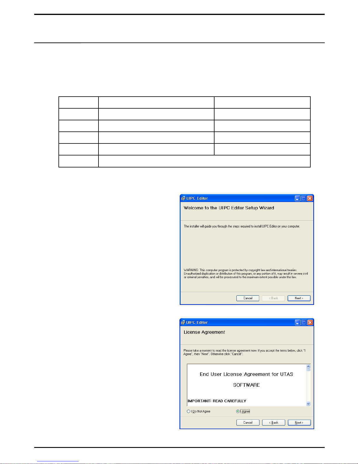
1. Execute UIPC Editor.msi to start
installation of the UIPC Editor program.
The installation program is contained in the
CD provided at the time of purchase.
2. Read the License Agreement, check “I
Agree”, then click on [Next>].
※ Requirements to run UIPC Editor are:
I. Program Installation
※ If NET.Framework 3.5 SP1 is not installed
in your PC, please have it installed before
installing UIPC Editor.
Page 4
4
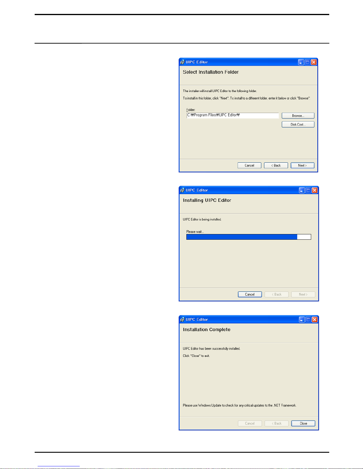
3. Check the folder in which the Program is
to be installed, then click on [Next>].
The installation path for UIPC Editor is
UIPC Editor in Program Files in C Drive
as default.
4. Installation will take about 2 -3
minutes to complete.
5. When installation is complete, click on
[Close] and execute UIPC Editor.
Page 5
5
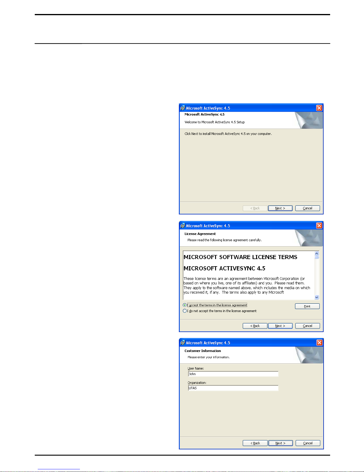
1. Execute ActiveSync4_5(Korean).msi to
start installation of the ActiveSync program.
The installation program is contained in the
CD provided at the time of purchase.
UX3500 Touch Panel Terminal uses its own USB port for communication with a PC through
which it receives data generated on UIPC Editor. To enable this USB communication, the
ActiveSync program must be installed.
2. Installation of Microsoft ActiveSync
2. Select “I Agree” to the User License
Agreement, and click on [Next].
3. Enter the User information, then click on
[Next].
※ Window Vista Users must install
Window Mobile Sync Center.
Page 6
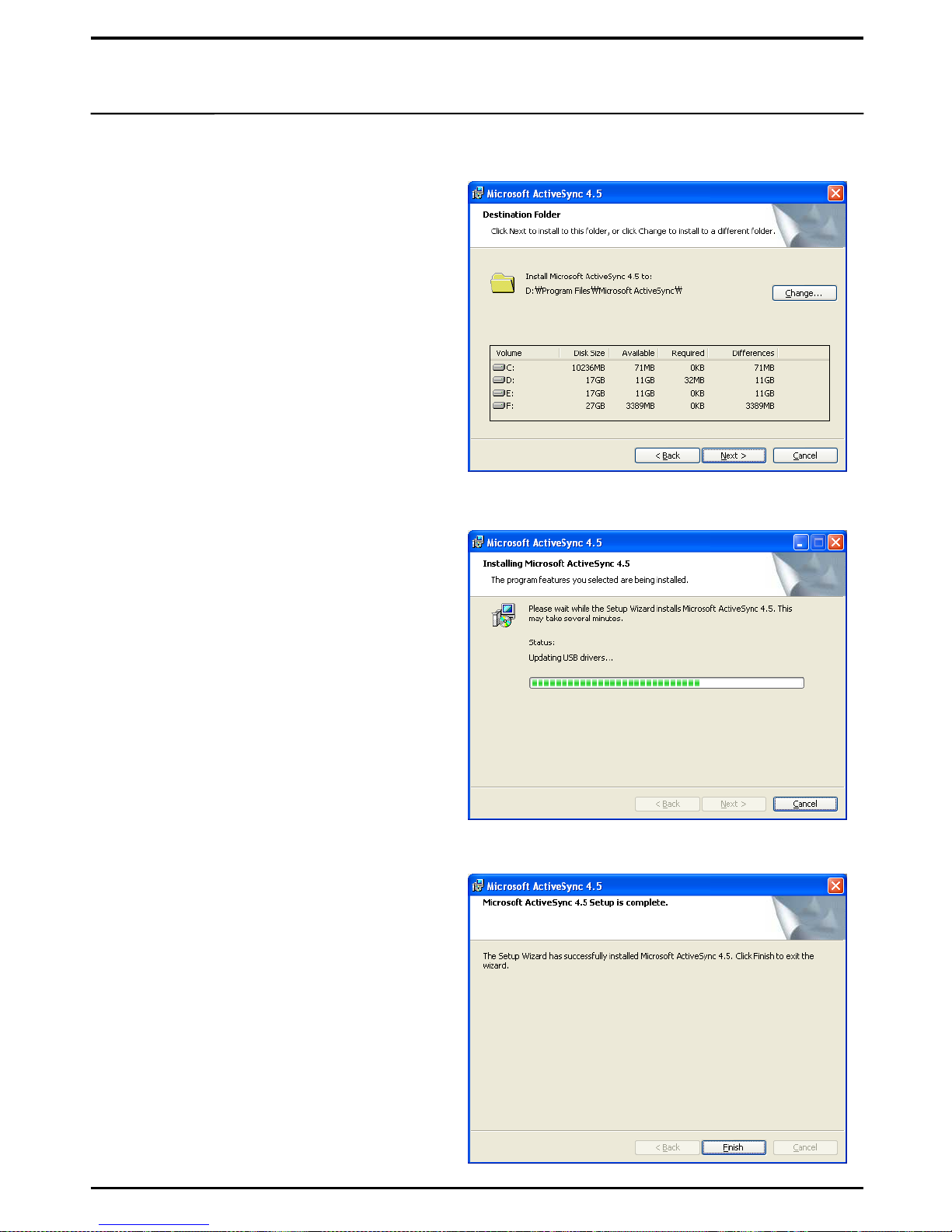
4. Select the drive and the folder to install
ActiveSync, then click on [Next] to start
installation.
6
5. Installation is under progress.
6. Click on [Finish] to complete installation
of the ActiveSync program.
Page 7
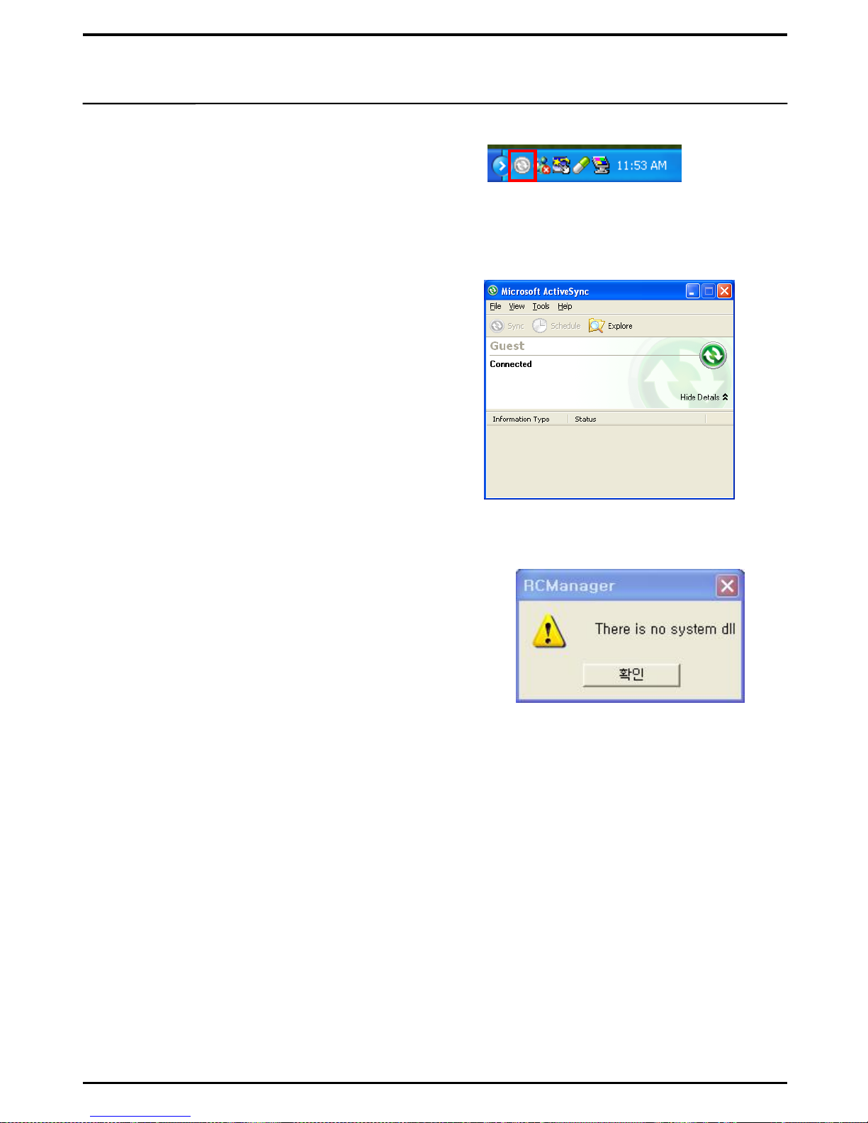
7. Upon completion, the ActiveSync icon
will appear in the Window Tray on your PC.
7
※ If UIPC Editor is executed without ActiveSync being
installed, the error window will pop up. Please install
MS ActiveSync before using UIPC Editor.
※ Window Vista users must install Window Mobile Device Center instead of ActiveSync.
Window Mobile Device Center can be found at and downloaded from the Microsoft web site.
8. On the following screen, select the [Search]
menu to view folders and files stored in
UX3500.
As long as UX3500 is connected properly to
your PC, you can send data that are
processed on UIPC Editor.
Page 8

1. From Control Panel, select „User Account’.
8
2. Click on „Enable/Disable User Account Control‟.
3. Untick „Protect PC with User Account Control‟ (leaving the box blank)
3. Setup for Window Vista Users
Window Vista users must release the Vista security settings to ensure normal operation
of UIPC Editor.
4. Click on „Confirm‟ and restart the PC.
Page 9
9
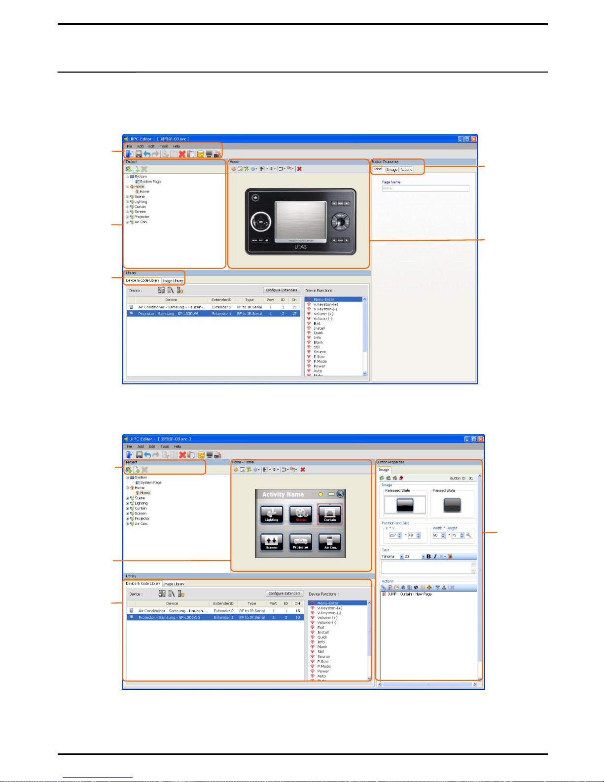
[Activity Properties Edit Screen]
[Touch Panel LCD Page Edit Screen]
II. About Program
1. UIPC Editor Configuration
The UIPC Editor screen is divided into (1) Activity Properties edit screen that sets functions for the
external buttons of UX3500; and (2) Page edit screen that configures the Touch Panel LCD screen.
Basic
Menu
/ Icon
Activity &
Page
configuration
Selectable
Libraries
Label / Image
Action
External
buttons of
UX3500
To create
New Activity
& Page
Touch Panel
LCD Screen
To Edit
button
actions
Device &
Code Library
Page 10

10
2. Menu & Icon
1. File
① New Project : to start a new project file. (Ctrl + N)
② Open Project : to open a saved project. (Ctrl + O)
③ Close Project : to close the current project. (Ctrl + F4)
④ Save Project : to save the current project. (Ctrl + S)
⑤ Save Project As : to save the current project in another file name.
⑥ Download to Controller : to send the project to UX3500. (Ctrl + D)
⑦ Exit : to end PC Editor.
2. Add
① Activity : to add a new Activity to the project. (Alt + A)
② Page : to add a new Page to the Activity. (Alt + G)
③ Button : to add basic Buttons to the screen during screen setup. (Alt + B)
④ Panel : to add basic Panels to the screen during screen setup. (Alt + P)
⑤ Text : to add a window for text entry to the screen during screen setup .
(Alt + T)
⑥ System – IR Icon : to add the IR Icon.
The IR icon will only appear when the terminal sends control commands.
⑦ System – Text Field : to add a Text Field.
Text Field informs you automatically of name of each page.
⑧ System – Battery : to add the Battery icon that indicates the battery level.
⑨ System – Time : to add the Clock.
⑩ System – Date : to add the Date.
⑪ System – Page Number : to indicate the number of each page.
⑫ System – Setup Button : to add the Setup Icon.
The Icon will move you to the screen where you can set basic functions for the terminal.
※ System items are better setup in the System Page, without the risk of
duplication in other pages.
3. Edit
① Cut : to cut off the selected item. (Ctrl + X)
② Copy : to copy the selected item. (Ctrl + C)
③ Paste : to paste the cut or copied item. (Ctrl + V)
④ Delete : to delete the selected item. (Del)
Page 11
11
4. Tools
② Database – My Database : to open the database you had saved.
③ Database – UTAS Database : to open the database which UTAS provides.
④ Database – Other Database : to open the database which had been added
individually.
5. Help
Gives the version information of the current UIPC Editor, and provides help
topics.
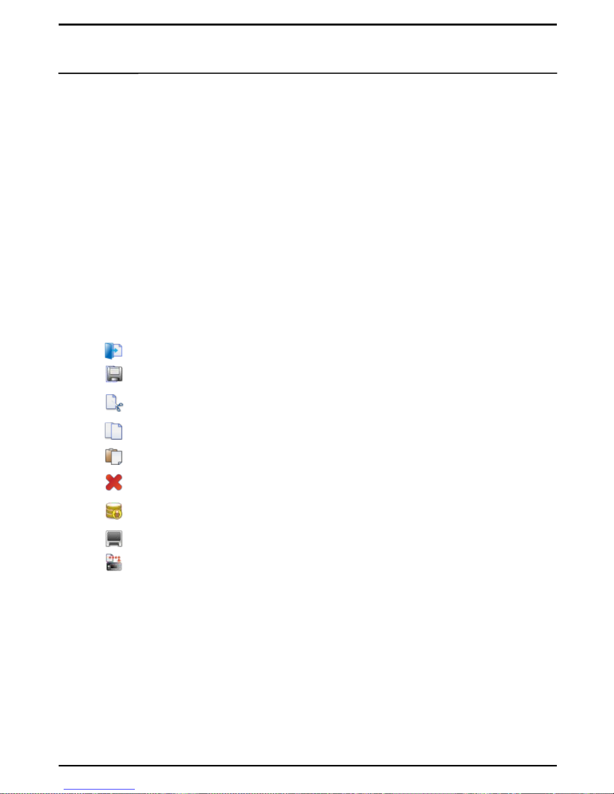
6. Icon
Basic Menu Icons are available for easy editing work.
① (Open Project) : to open the saved project file.
② (Save Project) : to save the current project.
③ (Cut) : to cut off the selected item.
④ (Copy) : to copy the selected item.
⑤ (Paste) : to paste the cut or copied item.
⑥ (Delete) : to delete the selected item.
⑦ (My Database) : to open the database you had saved.
⑧ (Emulator) : to execute Emulator to check data virtually.
⑨ (Download) : to send the project to UX3500.
① Emulator : to execute the Emulator function. ( Ctrl +M )
Page 12
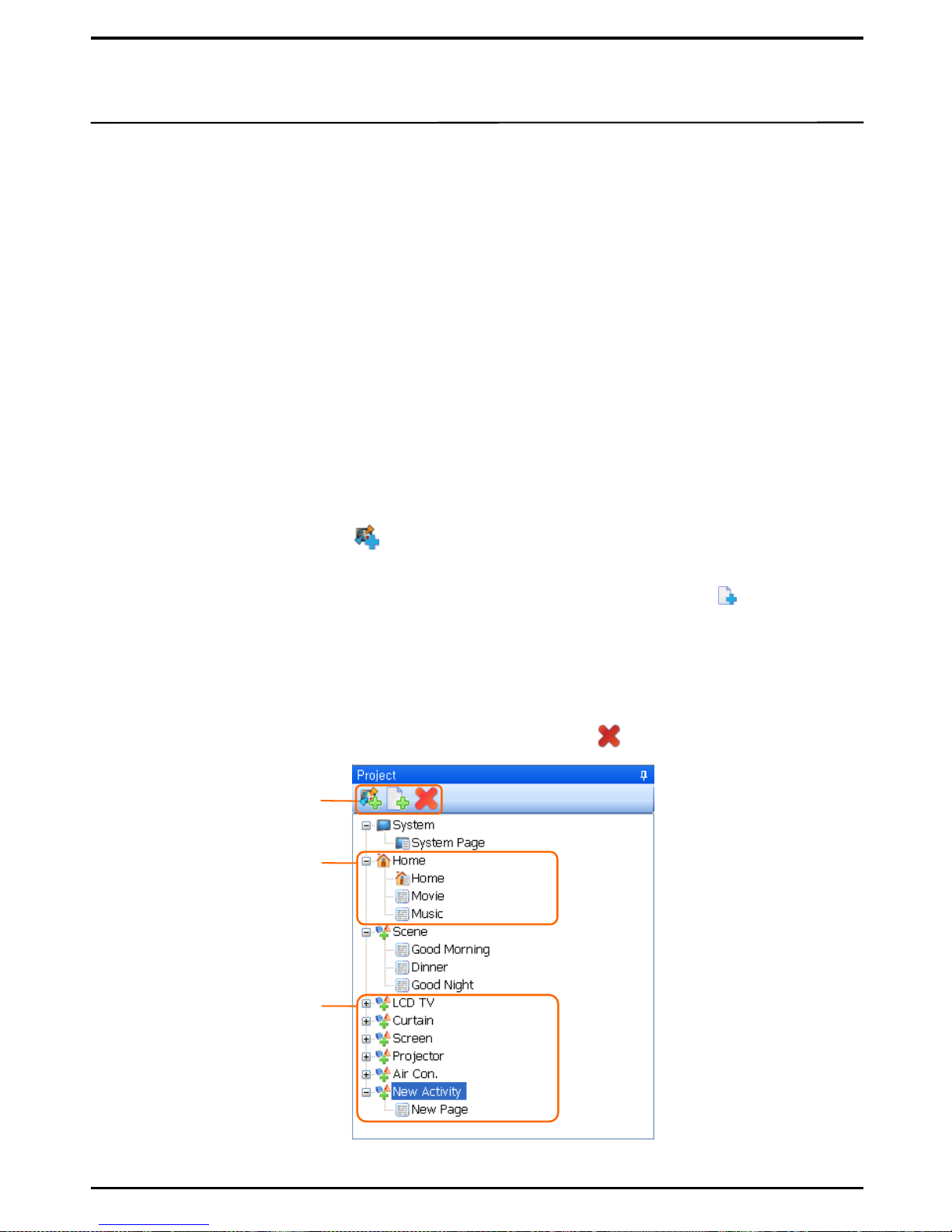
On Project of UIPC Editor, creation of new folders/pages is made easy during the UX3500
screen configuration. On the Home Page, new devices or pages can be added, and names can
be changed.
① Insert Activity: Click on the icon in Project to add a new Activity.
The number of Activities corresponds to the number of devices to be controlled.
② Insert Page: Upon selecting the Activity to which Page is added, click on the icon in
Project to add a new page. You can add as many pages as you want to account for the
number of buttons.
④ Delete: Select an Activity or a Page to delete, and press the icon to delete.
1. System / Home / New Activity
③ Change Name: Double-click on the folder or page of which you wish to change name.
(This function is also enable in Label.) Name change is disabled however for System,
System Pages and HOME.
3. Project
① System : Screens and functions that are configured in the System will apply to all pages
globally. Basic items such as IR Icon, Time, Date, Battery and Setup Button are the main
constituents, but the frequently used buttons can also be added for your convenience. (e.g.
Receiver Volume, Light On/Off and so on)
② Home : HOME is the first page of UX3500. HOME can be configured with devices that are
subject to control, and with macro buttons. The Jump Action can also be applied to each
button for easy move to the corresponding device.
③ New Activity: Control buttons can be configured in more detail for each device individually
that had been configured on HOME. Based on the remote control of each device, you can edit
buttons on New Page and apply Actions to the corresponding buttons.
In the Activity Properties setup window, you can also apply Actions to the external buttons of
UX3500.
2. Insert Activity / Insert Page
[Project Edit Screen]
12
Project Icon
Home Page
New Activity
(Rename)
Page 13
1. External Buttons
4. External Buttons/ LCD Touch Panel
13
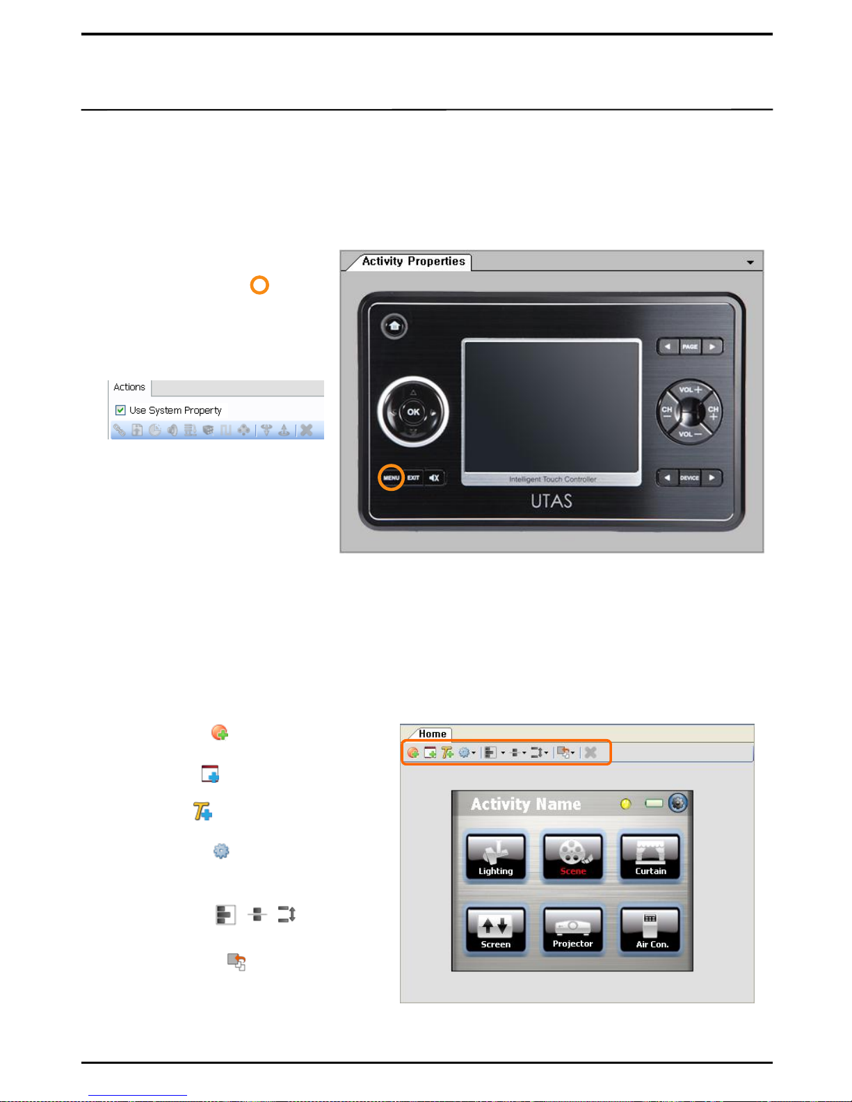
There are a number of buttons available with UX3500 for user convenience including Home,
Menu, Exit, Mute, up/down/left/right keys, Page, Device, Volume and Channel. You can set
functions to each of these buttons to enhance user convenience even further.(Buttons will offer
the basic default function if not setup additionally.)
① Select Button: When you
select a button to add
button functions , will
appear.
③ Add Function: Upon
unticking „Use System
Property, buttons become
activated. Select an Action
and enter its value.
(see P27 for adding
Button Actions)
Buttons of the LCD Touch Panel can be customized. From UIPC Editor, use the Mouse to move and
download backgrounds or buttons to UX3500. The same screen will be shown in UX3500.
2. LCD Touch Panel
② New Panel( ) : Basic panels will be
newly created.
③ New Text( ) : Basic texts will be newly
created.
④ System Icon( ) : System Icons such
as Time, Date, Setup, Battery, IR
Indicator will be created.
⑤ Align Items ( , , ) : Newly
created icons can be aligned.
⑥ Reorder Items( ) : Newly created
icons can be re-organized.
① New Button( ) : Basic buttons will
be newly created.
② Untickt „Use System Property‟
at top right side of the
screen.
Page 14
1. Label
5. Properties
14
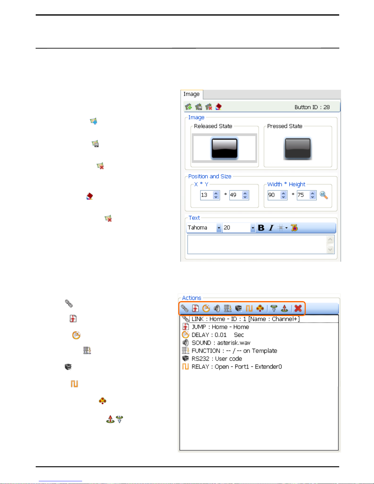
The Action function enables characteristics of UX3500 external buttons and Touch Panel buttons to
be entered. Multiple Action functions can be set for a single button enabling easy creation of Macro.
3. Actions
① Link( ) : to link to functions of other
buttons.
⑤ RS ( ) : to add the RS232/485 function.
③ Delay ( ) : to add Delay time.
⑥ Relay( ) : To add the Relay function.
② Jump( ) : To jump to other pages.
⑦ Channel Macro( ) : To enter specific
channels.
④ Function ( ) : To add the IR function.
⑧ Move Up, Down ( ) : In case of
multiple Actions, the selected Action
can be moved to another location (or
in another sequence).
Names of New Activity and each page can be changed.
2. Image
You can change Item Images such as Buttons
and Panels of the screen.
① Add Image( ) : To add new image to
the selected item.
② Save Image( ) : To save the selected
item.
③ Delete Image( ) : To delete the
selected image.
※ Only the image, not the Item will be
deleted.
④ Fill Color ( ) : To set color for the
selected item.
※ Selected color is displayed only after
doing Delete Image( ).
⑤ ID of each item will be displayed in
numbers. Location and size can be modified.
⑥ Name of each item in text can be entered.
(see P27 for adding Button Actions)
Page 15
6. Library
15
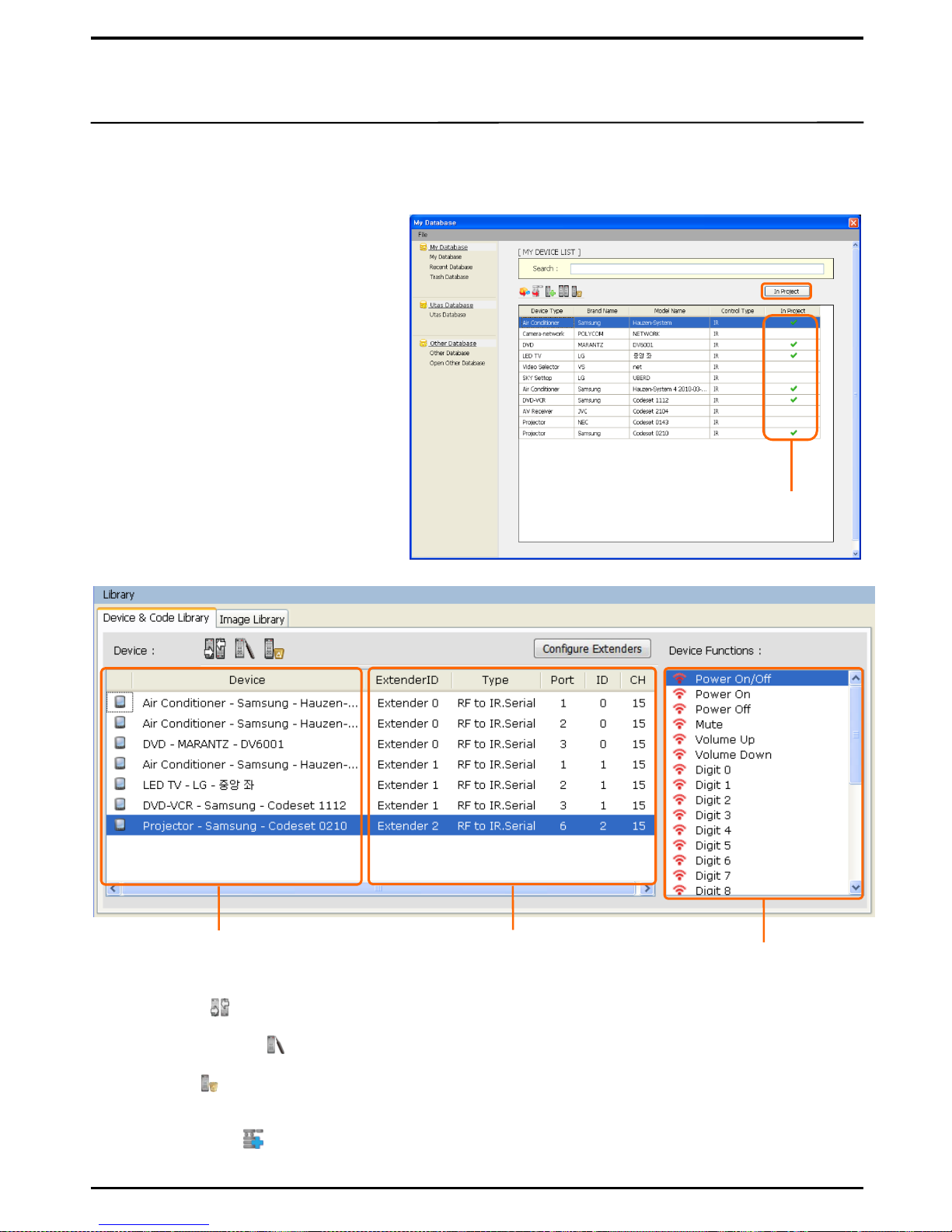
Device Library opens device data from database to enable easy assignment of button properties.
1. Device Library
① Search from the UTAS database the
code of the device to control, and
click on „Device to My Database‟ to
save in My Database.
② Select the device to control from
My Database, and click on „In
Project‟.
③ Check if the devices checked by In
Project are added to Device Library.
See if correctly ticked
④ Replace ( ) : to replace data of the selected device with other data.
⑤ Function Setup ( ) : to setup IR, RS232 values for the selected device data.
⑥ Delete ( ) : to delete the selected device from Library
Devices added to ‘In Project’
from My Database
Data item of each device
button
⑦ Data items of the Device Functions can be entered as the Button Property using the Add
Function Actions( ).
※ (see P19 for ‘Database
Management’ for detail.)
Controller receiver set by devices
(Controller CH, ID, Port No…)
Page 16
16
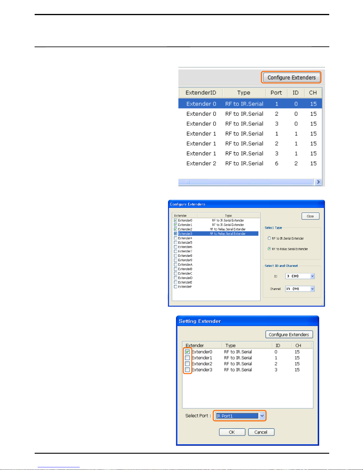
2. Extender( Controller ) Setup
① Click on „Configure Extender‟ in Device
Library to open the Extender setup window.
② Tick all Extenders connected to a
device to add Extenders.
③ Select Type : to setup Extenders for IR
device and Relay device.
④ Select ID and Channel : to setup ID
of the selected Extender and
channels.
⑤ Upon completion, click on „Close‟ to
close the window.
⑥ Select and tick the device from
Device Library to connect to the
Extender.
⑦ Select Port : Select the corresponding
port of the Extender that is
connected to a device.
※ The ID located at the bottom of
Extender and the CH switch must
match with the setup values.
Page 17
17
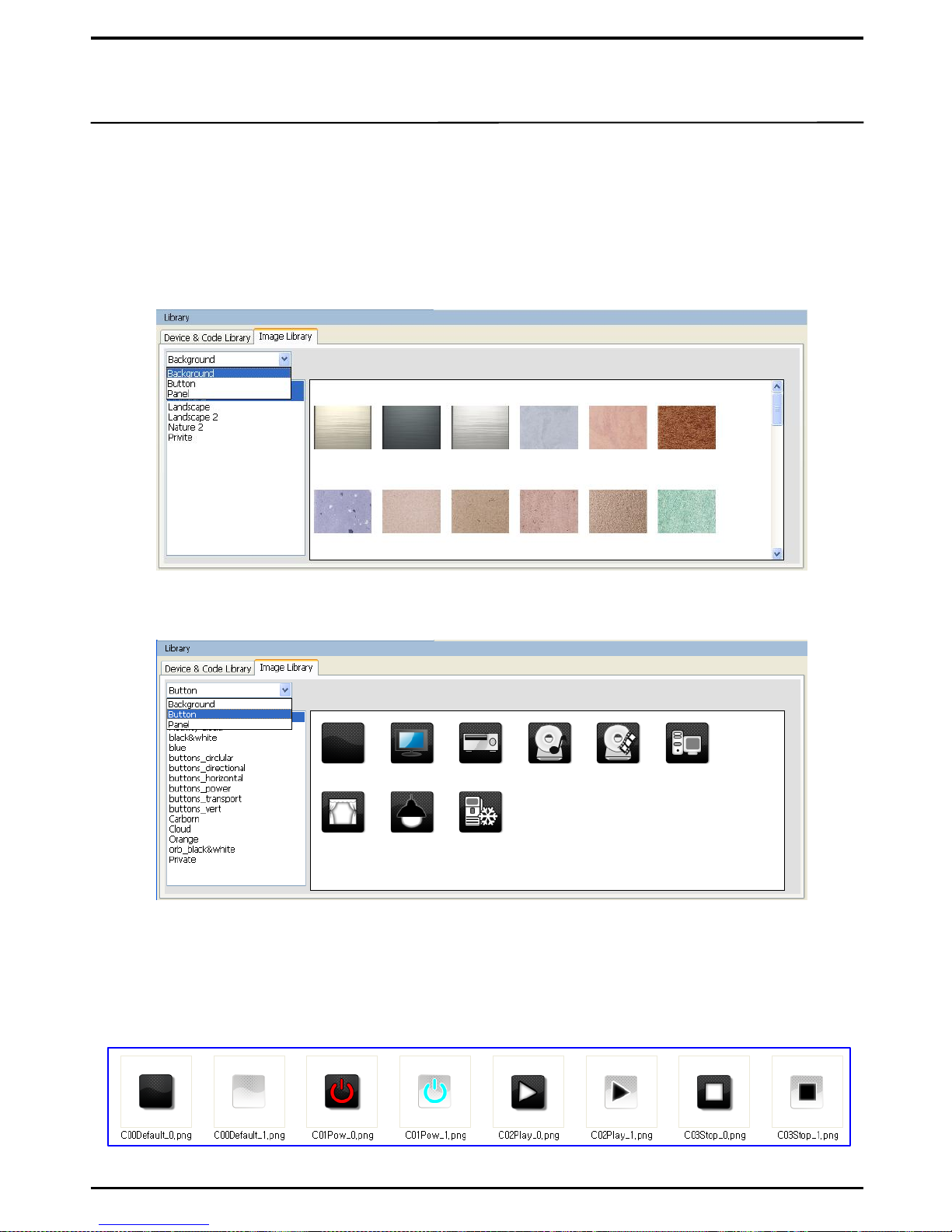
3. Image Library
Basic background images and button designs are available with UIPC Editor. You can add other
backgrounds and buttons to dress the UX3500 Touch Panel to your preference.
① Background : You can use any of the given Backgrounds to dress the HOME and New Activity
pages. You may also use other backgrounds as long as they are 320X240(96dpi) in size and in
jpg or png file formats. Save these files in any folder through this path: C:\Program
Files\UIPC Editor\Gallery\background\ any file name of your choice.
② Buttons : In addition to the basic buttons provided with the product, you may create your own
buttons.
[Newly added background images]
C. Save in any folder of your choice through this path: C:\Program Files \UIPC Editor \Gallery
\button \folder of your choice.
b. Size of both buttons must be the same and saved as a png or a jpg file.
[기본 제공 버튼 이미지]
a. Buttons should be created into two categories: the Released State and the Pressed State.
Although you may use the same name for these two buttons, you must add _0 at the end of
the name for the Released State button, and _1 for the Pressed State buttons for distinguish
one another. (see the picture as below)
[Name differentiation for buttons]
Page 18
18
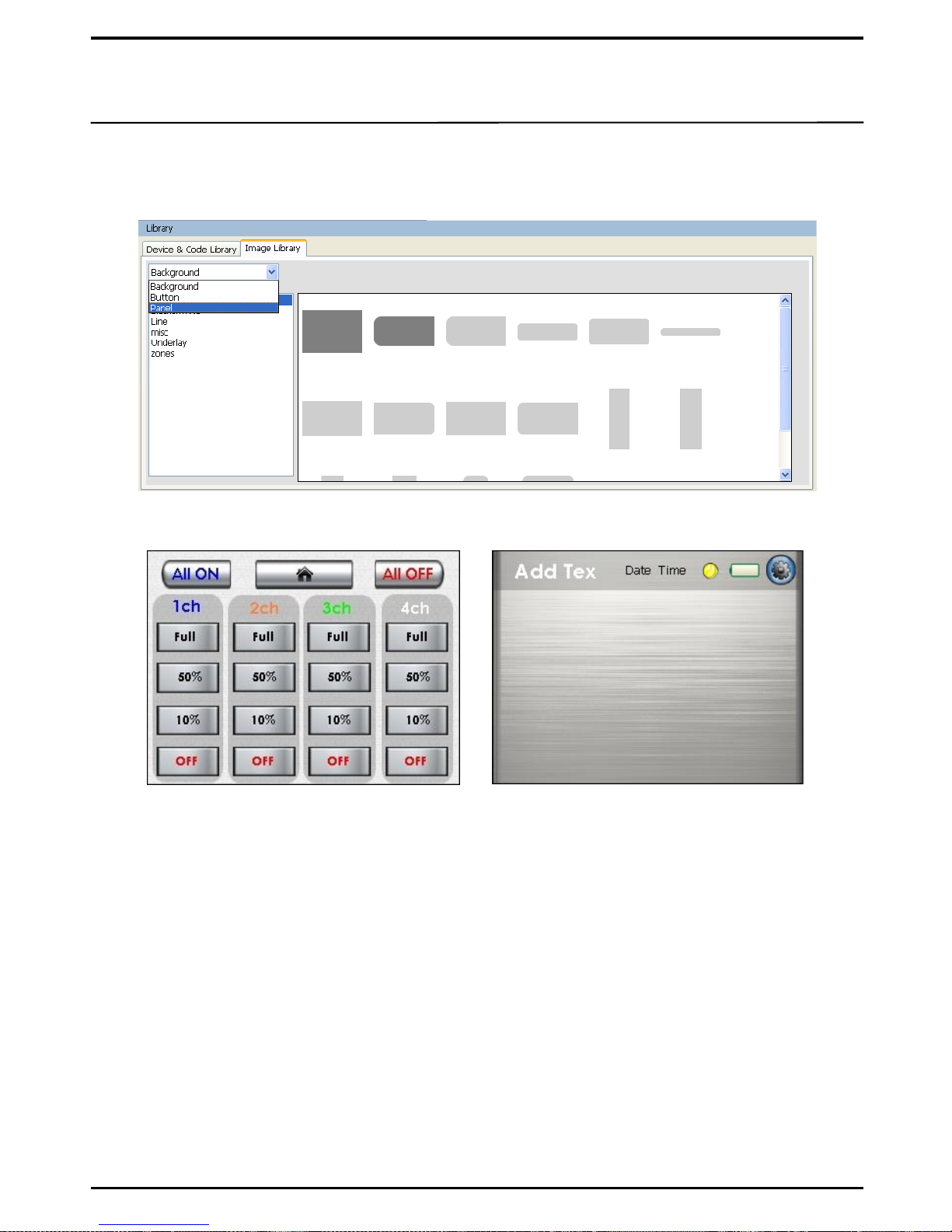
③ Panel : Panel is mainly used as background for Text or Buttons. You may also use other Panels
as long as they are converted to a png file. Save these files in any folder through this path:
C:\Program Files\UIPC Editor\Gallery\Panel\ any file name of your choice.
[Example of a Panel applied screen]
[Panel images]
※ The png file format is recommended to keep Panel images translucent; jpg
without the transparent effect will completely shadow the background .
Page 19
7. Database Management
19
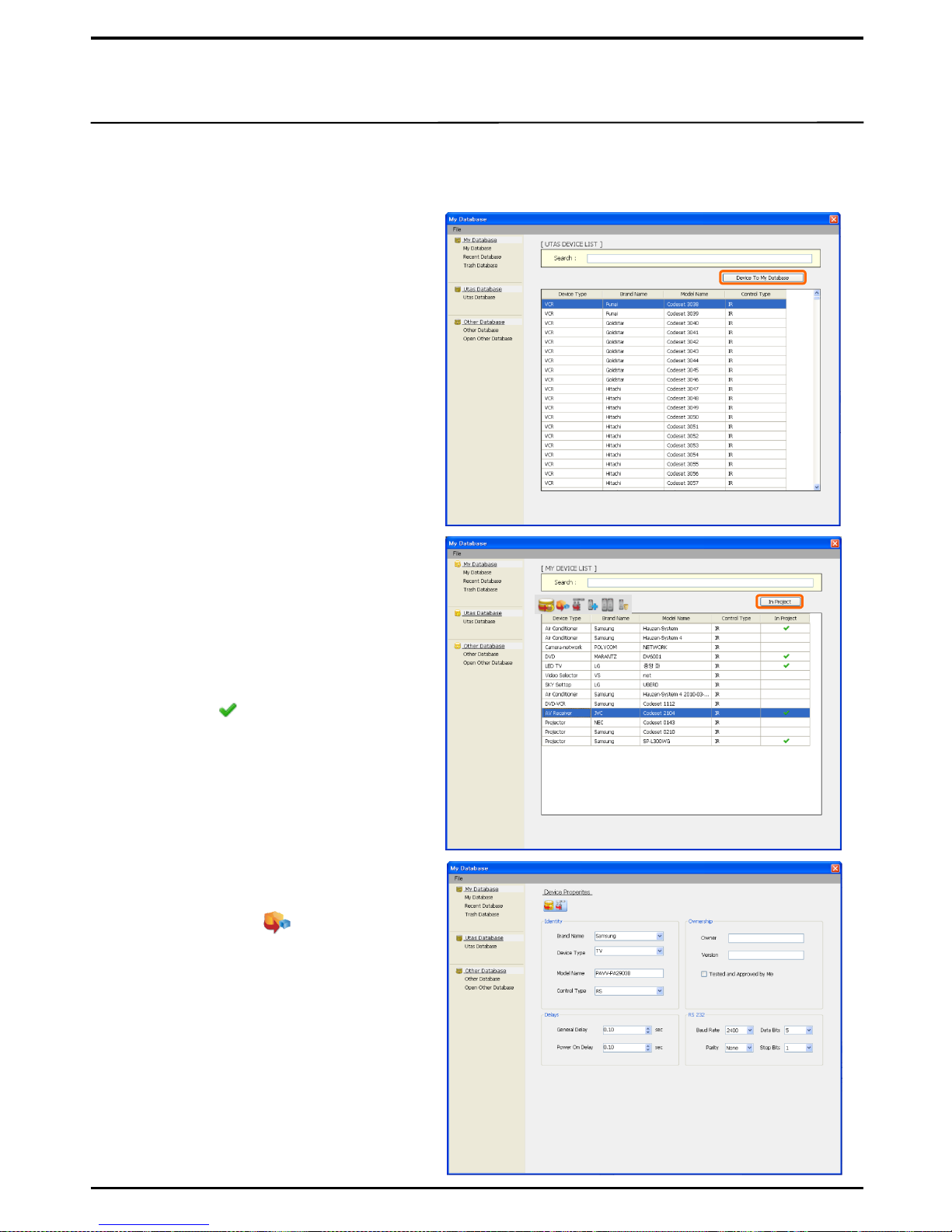
The UTAS Database provided with UIPC Editor offers basic control codes to control devices. You
can search the control codes, save them onto My Database and use for your own purposes. If a
device comes without the control code, you may get it to Learn the IR values. Alternatively, you
may enter RS232 values directly on Editor.
1. UTAS Database
① Search : to search the object to
control by device name or by brand.
② Device to My Database : Select the
control code from the searched list
which corresponds to the device, and
click on Device to My Database.
③ Check My Database : to check if the
list of selected devices is saved.
2. My Database
① Search : to search the object to control
by device name or by brand.
.
② In Project : Select the control code
from the list saved in My Database
which corresponds to the devices and
click on In Project. The selected date
is ticked ( )
③ Check Device Library: When the My
Database window is closed, the
selected list is saved in Device
Library.
3. Database Management
① Device Properties : Click on the Device
Properties Icon ( ) to view the device
property.
② Identity : to identify name of the
control code, type and IR/RS
properties.
③ Ownership : To set Owner and Version
to the control codes.
④ Delays : to adjust Delay setup values.
⑤ RS232 : to set values to Baud Rate,
Data Bits, Parity, Stop Bits in case of
RS232 controlled devices
Page 20
20
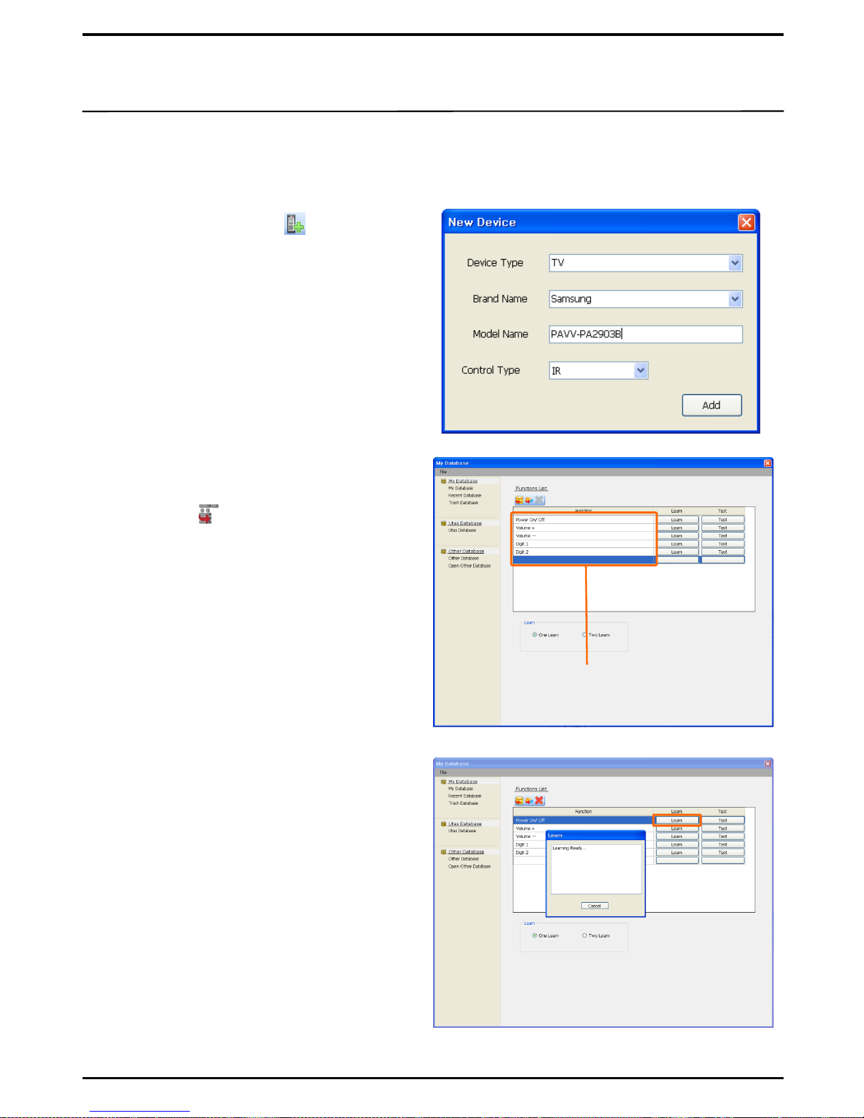
4. To Make IR Device Database (Learn / Test)
④ Check if the PC and UX3500 are correctly
connected by ActiveSync.
② When the device is registered with My
Database, click on the Device
Function( ) button.
⑧ Click on Test to check if Learn has been
successful.
If data is unavailable from the UTAS Database for a particular device in use, you can get your
remote control to learn the system. This is commonly used when it is difficult to differentiate the
device‟s code sets.
① Click on New Device ( ) from the My
Database window to register a device for
learning.
a. Device Type : To register the type of device
(such as TV, DVD, VTR)
b. Brand Name : to register name of the
manufacturer.
c. Model Name : to enter model name (in full)
for easier control.
d. Select IR for Control Type.
Check all entries and click on Add to register the
device.
③ Click on Function Item to register the name
of Remote Control button for learning.
⑤ Select the item for Learn, and click on the
Learn button.
Function Item
⑥ When the „Learn Ready‟ window appears,
press a button on the remote control
pointing toward the IR receiver of UX3500
to continue.
e.g. Power On/Off , Volume +, Volume –
Digit 1, Digit 2, ….., etc.
⑦ Upon completion, the Learn Success
message appears, and the window will be
closed automatically.
※ For „Learn‟, keep the distance of 2-3cm
between the remote control and UX3500 in a
„not too bright‟ area.
If Learn is unsuccessful, check the connection
between the PC and UX3500, and try again.
Page 21
21
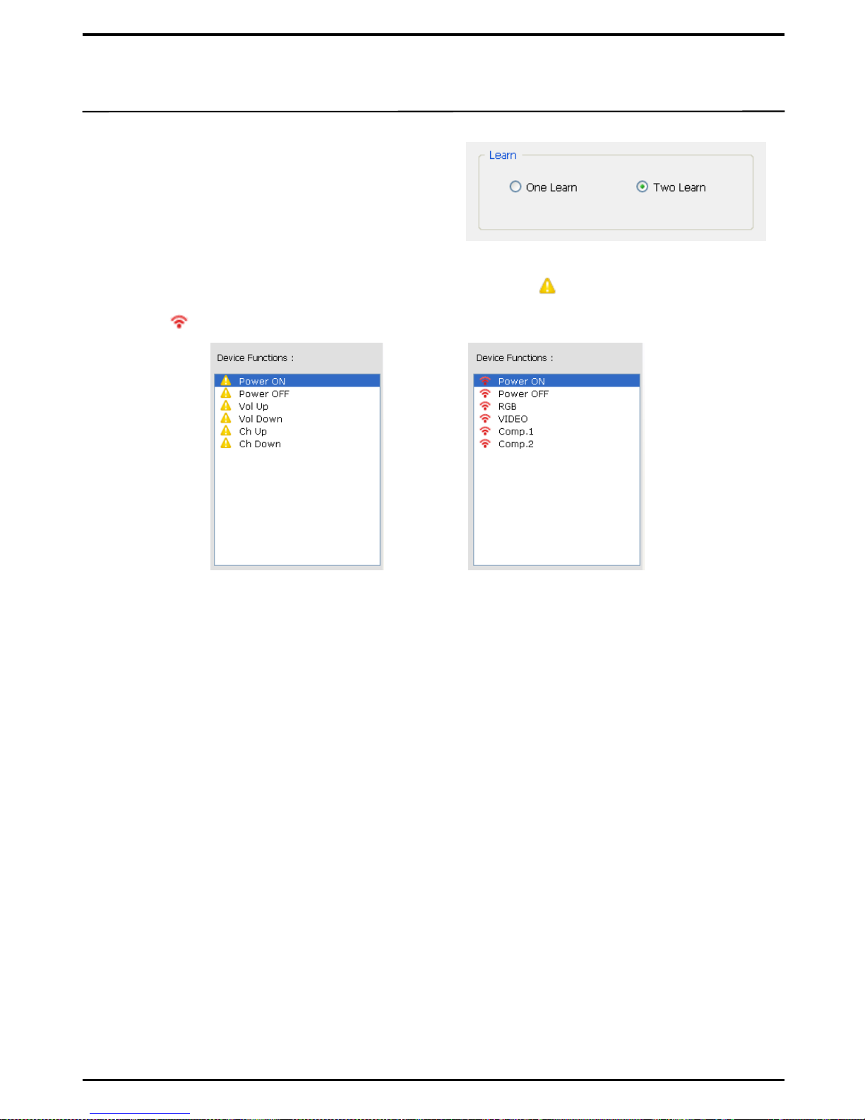
⑨ For an ordinary remote control, you can
proceed with Learn by ticking „One Learn‟.
For a toggle typed remote control, tick
„Two Learn‟ and repeat „Learn‟ twice.
※ A Toggle Remote Control refers to the
one which has two IR data per button.
⑩ If a function has not completed „Learn‟, it will be marked with on Device Functions window.
This indicates that there is no IR code. If a function has completed „Learn‟, it will be marked
with .
[Items after Learn][Items before Learn]
⑪ Learning methods may vary depending on the type of Remote Controls.
For an ordinary Remote Control, press and hold a Remote Control button until Learn is complete.
If Volume or Menu Cursor staggers during the operational test, short-press the corresponding
Remote Control button to proceed with Learn.
Page 22
22
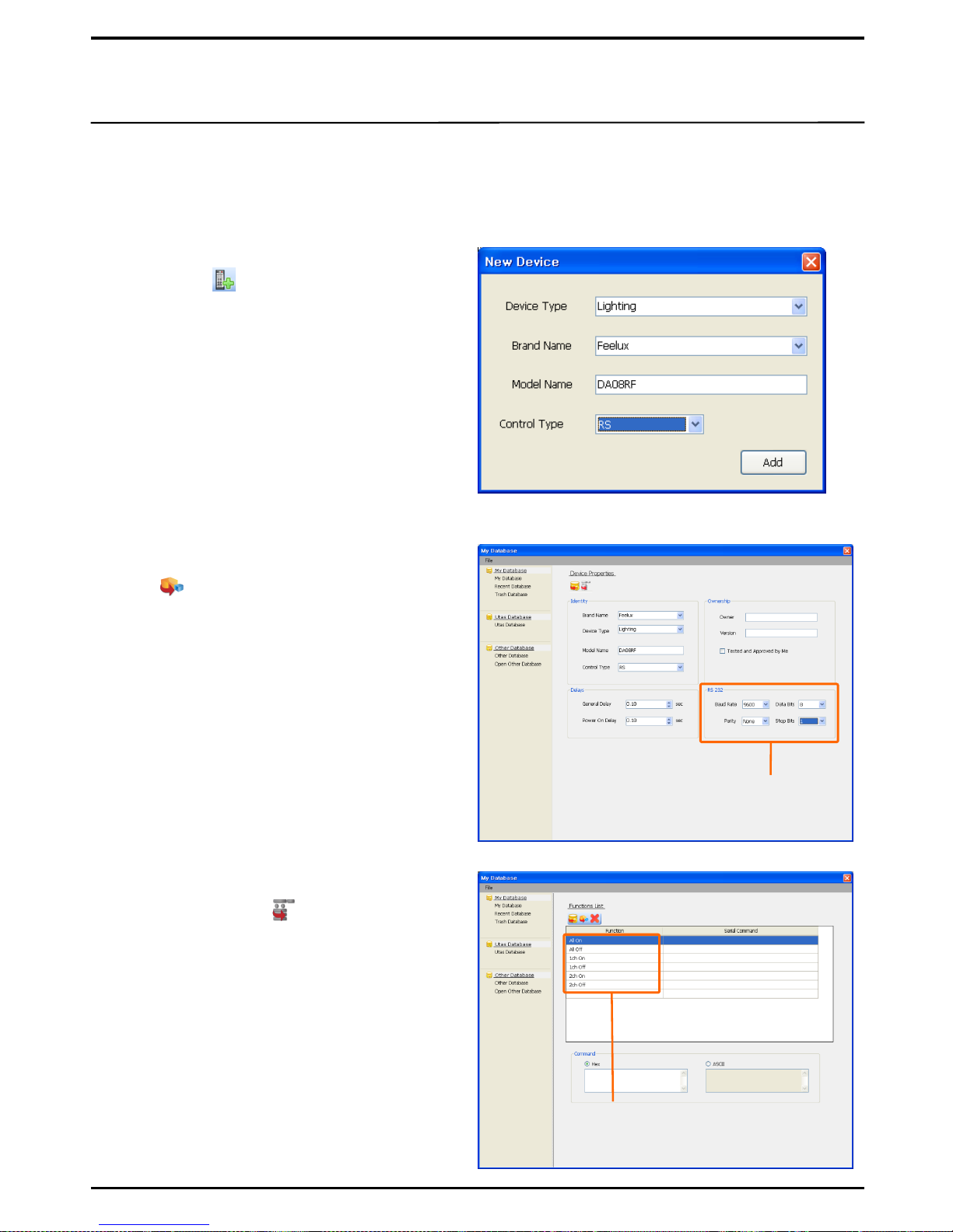
5. To make database for RS232C, RS485 devices
You can create Database to manage protocol codes for RS232C or RS485 compatible devices and
to save time to enter such codes.
① In the My Database window, click on New
Device ( ) to select a device to
register.
a. Device Type : Register a device such as
Lighting or Projector.
b. Brand Name : Register the manufacturer
of the device.
c. Model Name : Enter the full model name
as this will help to manage better.
d. Control Type: From the two control
types i.e. IR and RS, select RS.
Check if all items are entered, then click on
Add to register the device.
⑤ Select a code type (ASCII or HEX) for
Control Code.
※ Most RS232C/RS485 compatible devices
use HEX.
③ Upon entering the above values, click on
Device Function .
Function Items
Examples of Functions Items: ALL ON, ALL
OFF, Power On, Power Off
Input 1, Input 2, RGB, Video
② Once registered, click on Device Properties
( ) to enter setup values for the
RS232C communication.
※ The same values (numbers) provided by
the manufacturer of corresponding device
must be entered for Baud Rate, Data Bits,
Parity, Stop Bits to ensure proper
communication with the corresponding
device.
Protocol
communication
numbers
④ Click on each of the Function Items to
register the button name of remote
control for Learn
Page 23
23
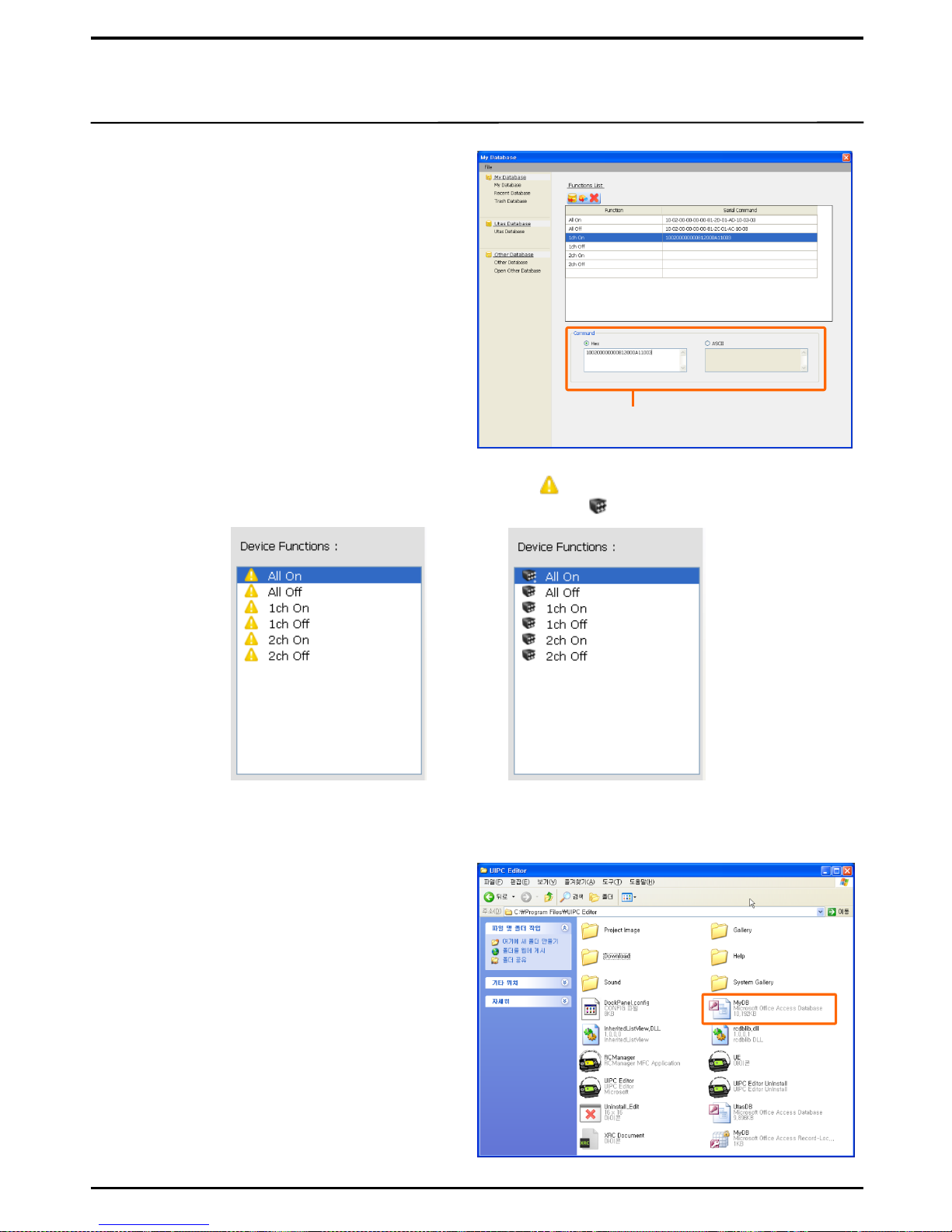
⑥ Enter the code (HEX or ASCII as
supported by the manufacturer) in the
Command window.
※ Enter the code value without a space.
Incorrect entry will disable the
corresponding device to operate.
To enter Protocol
numbers
⑦ The Function item without code will be marked with ( ) in the Library Device Functions
window. The Function item with code will be marked with ( ).
[Item with Code][Item without Code]
6. Save & Open from My Database
① If you wish to reinstall or use UIPC Editor in
another PC, save the MyDB file separately.
② The MyDB file is located in the UIPC
Editor Folder through this path:
C:\Program Files\UIPC Editor
③ Copy MyDB, save separately, and Paste
onto the UIPC Editor Folder of the new
PC.
※ When saving on XRC, the MyDB data
(which is checked as In Project) will also be
saved on XRC.
Page 24
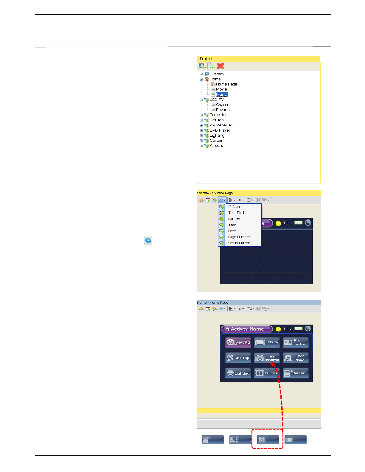
1. To configure Page Screen
24
III. To Make New Project
1. Project List Configuration
① New Activity: adds new activities
corresponding to the number of devices
controlled by the Project. In addition, it adds
Macro.
② Add Page: adds new pages to a new activity
if there are many buttons on the remote
control of the corresponding device. If there
are many devices to control, please go to
HOME and add a New Page.
③ Change Name: changes the name of New
Activity to the device name for easy
identification of the lists.
2. System Page Configuration
① Button Select: adds an item of your choice
by clicking on the Setup icon ( ) in the
System Page.
② Location Select: Positions of the icons
configured in the System Page are shown
globally in all pages. It is recommended that
icons are aligned in a linear fashion either at
the top or the bottom of the screen, rather
than in the middle.
All buttons configured in the System Page are
shown globally in all pages. These include Date,
Time, Battery and Setup among others.
3. Home Page Configuration
① Select Background: Select and move a
background item by the mouse from
Background in Image Library, to the editing
screen.
The Home Page is the main page of UX3500.
Remote controls of devices are configured in the
Home Page.
② Select Button: Select and move a button item
by the mouse from Buttons in Image Library,
to the editing screen.
③ If there are many button items to be used for
a remote control of device, add a New Page
in the Home page.
Select and move.
※ The same background will be applied to the
new pages added to Home.
Page 25
25
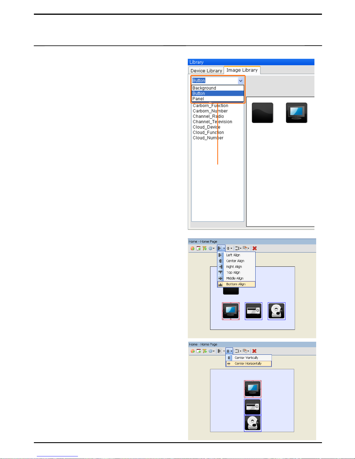
4. Activity Page Configuration
① Select Background : Select and move a
background item for Activity Page by the
mouse from Background in Image Library, to
the editing screen.
Activity Page shares the same concept as the
remote control of each device. All buttons of
remote control can be edited, or alternatively, the
buttons frequently used can be grouped together
and edited collectively.
② Select Button : Select and move an item to be
used for the remote control, by the mouse
from Buttons in Image Library, to the editing
screen.
③ Select Panel : In the same way as above,
select and edit a Panel. Panels are normally
used for text backgrounds or for background
under a button.
④ If there are many button items to be used for
a remote control, add a New Page to Activity.
5. Item Align
Position of the items in Edit Screen can be aligned.
① Item Select: Drag and select items for
alignment in the edit screen. The fiducial item
for alignment will be outlined in red.
② Align Select: The method of alignment can be
selected. From the fiducial item, you can select
alignment to the left, the center, the right, the
top, the middle or the bottom.
6. Center Align
It moves all selected items to the center of the
screen.
① Select Item: to select items for alignment.
② Center Vertically: to move the selected item to
the center vertically.
② Center Horizontally: to move the selected item
to the center horizontally.
Select
Background,
Button and
Panel
※ Although you can select different backgrounds
for each of Activities, the background of the
first page will be applied to the newly added
page.
Page 26
26
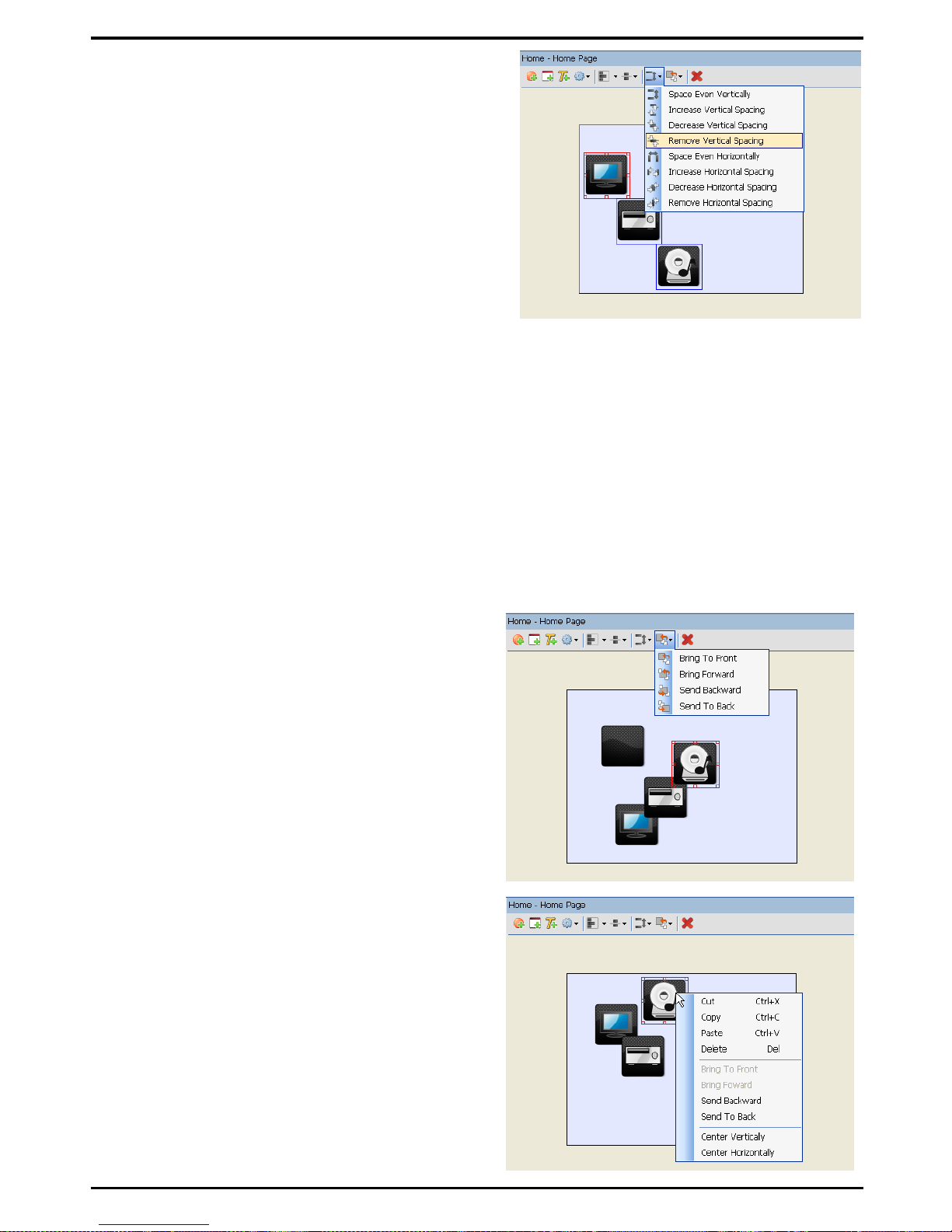
7. Align Adjustment
It adjusts space between the selected items.
① Select Item: Drag and select an item to align in
the edit screen. The fiducial item will be
outlined in red.
② Select Alignment: to select method of
alignment. Items will be aligned around the
fiducial item outlined in red.
a. Space Even Vertically : The vertical space between the items are
evenly aligned.
b. Increase Vertical Spacing : The vertical space between the
selected items increases in the regular proportion (2 pixel).
c. Decrease Vertical Spacing : The vertical space between the selected items decreases in the
regular proportion (2 pixel).
d. Remove Vertical Spacing : Items are aligned in such a way that they concatenate vertically.
e. Space Even Horizontally : The horizontal space between the items are evenly aligned.
f. Increase Horizontal Spacing : The horizontal space between the selected items increases in
the regular proportion (2 pixel).
g. Decrease Horizontal Spacing : The horizontal space between the selected items decreases
in the regular proportion (2 pixel).
h. Remove Horizontal Spacing : Items are aligned in such a way that they concatenate
horizontally.
8. Item Alignment by Priority
Order of items can be adjusted by the Item Alignment
by Priority function .
① Select Item: Click on the items to be aligned in
the Edit screen. The item subject to alignment
is outlined in red.
② Bring to Front, Bring Forward,
Send Backward, Send to Back:. Prioritize the
item using one of these functions.
9. Quick Item Edit
Select an item and right-click on the mouse to pop
up the quick edit screen.
① Basic Edit functions: include Delete, Copy, Cut,
Paste among others.
② Edit Priority or Position: Offers edit functions
such as Prioritizing items or Moving the
selected items to the center of screen.
Page 27
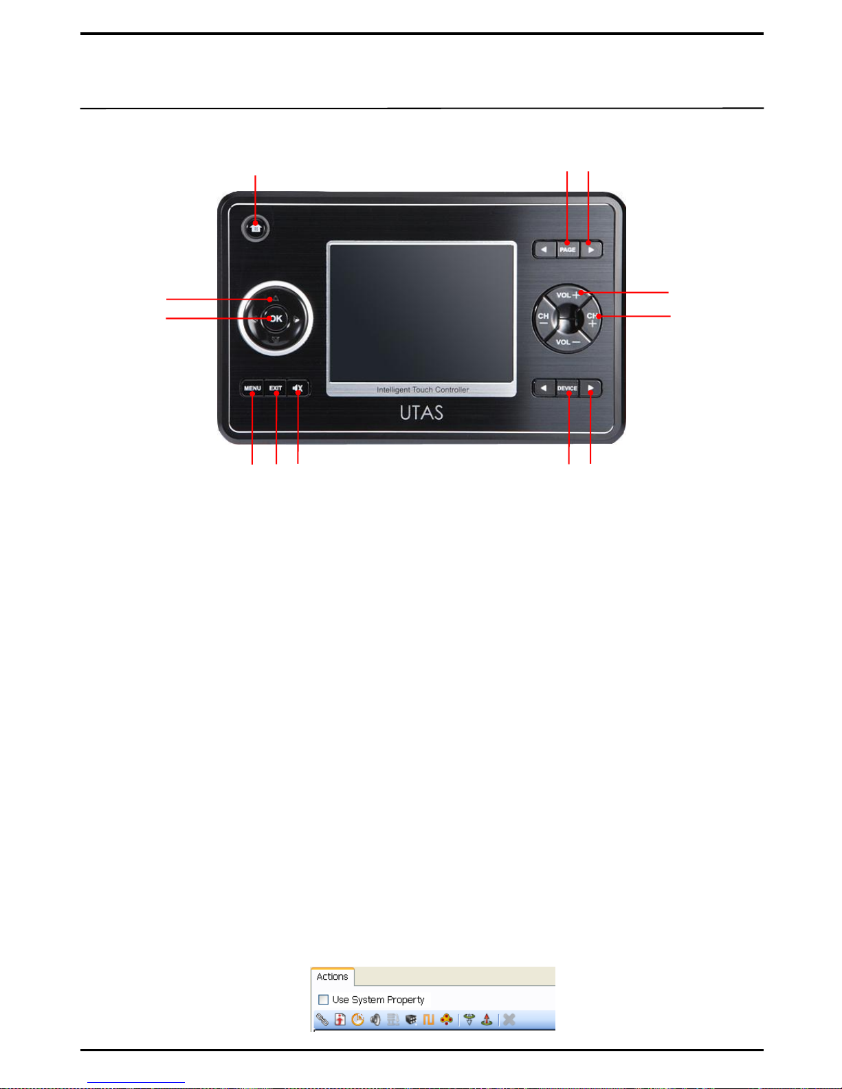
2. To setup Button actions
27
1. To setup actions for external buttons of UX3500
9
7
6
2
8
1
4 5
10 11 12
1 [HOME] Button
Sends you to the first Home Page. (default)
2 [PAGE] Button
Sets Home or any Activity page to move to Page 1. (default)
3 [PAGE ◀ , ▶] Button
Moves to the next or previous page. (default)
4 [DEVICE] Button
Sets to move to the first page of the first Activity which had
been registered with Device Home. (default)
5 [DEVICE ◀ , ▶] Button
Sets to move to the first page of each Activity in the order
or the reverse order of registration. (default)
6 [Volume +/-] Button
Sets to execute the volume control function of
each device.
7 [Channel+/-] Button
Sets to execute the channel select function of each
device.
8 [Cursor Control] Button
Sets to execute functions (such as Search Menu)
9 [OK] Button
Sets to execute functions (such as „OK‟)
10 [MENU] Button
Sets to execute the Open Menu function
11 [EXIT] Button
Sets to execute the Exit function
12 [MUTE] Button
Sets to execute the Mute functions
3
※ Any buttons other than the default buttons such as
Home, Page ◀▶, Device ◀▶ must be setup by User
to the characteristics of device in UIPC Editor.
→
Untick and setup for
Action functions.
Page 28
28
2. To setup Button actions
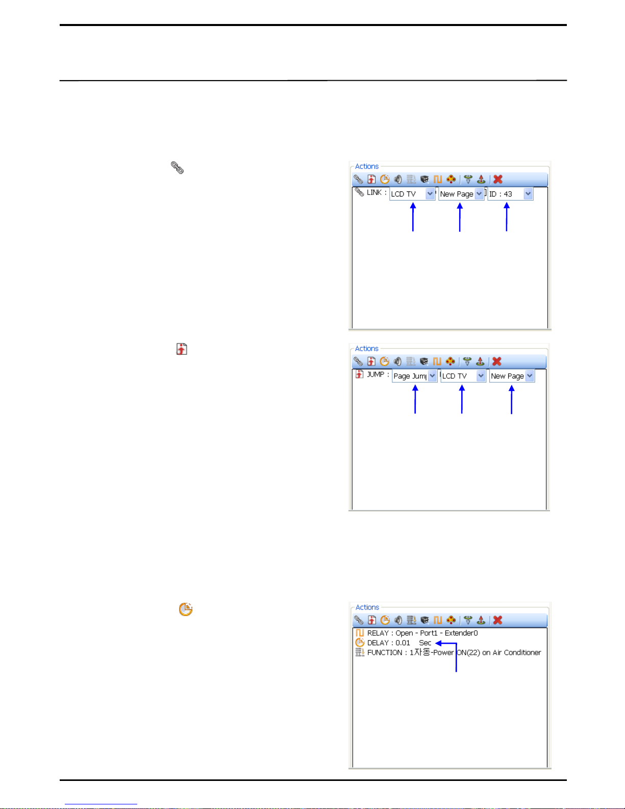
In Button Properties of UIPC Editor, Action functions can be set to the buttons. Not only the button
items shown on LCD screen, but also the external hardware buttons can be set with the Action
functions.
① Add Link Action( ) : To add another button
action to the selected button.
③ Add Delay Action( ) : If more than one Action is
linked to a button, you can set delay time between
each Action.
※ Too short a Delay Time may cause malfunction
between Actions. Delay time of 0.4~0.6 second is
recommended.
a. Activity : To select an Activity of the device to
which the button to link belongs.
b. Page: To select a Page of the device to which the
button to link belongs.
c. Select Button: Each button has its own ID number.
This function checks the ID number of a button
and select the button to be linked.
Select
Activity
Select
Page
Select
Button
Set Delay
Time
② Add Jump Action( ) : To jump to a particular
page. Often used to move to each Activity from
the Main Control page.
a. Page Jump : To move to a particular page. The
Activity and the Page to be jumped to must be
designated.
Select
Page
Select
Activity
Select
Jump
Action
b. Page Up : To move to the upper page from the
current page. This does not move you to the page
of other Activities.
c. Page Up : To move to the lower page from the
current page. This does not move you to the page
of other Activities
d. Activity Jump : To move to a particular Activity. It
moves you to the first page of the selected Activity.
e. Activity Up : To move to the first page of the upper Activity from the current Activity.
f. Activity Down : To move to the first page of the lower Activity from the current Activity.
.
g. Home : To move to the first page of Home.
Page 29
29
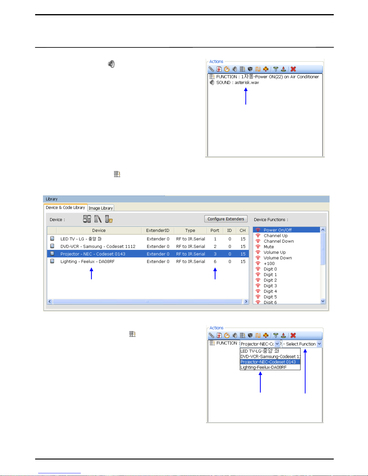
④ Add Sound Action( ) :. To play a particular
sound on button click. Sounds are saved in the
WAVE format in the folder through this path:
C:\Program Files\UIPC Editor\Sound
※ Certain chips mounted inside UX3500 may not
enable this function.
Select
Sound
⑤ Add Function Action( ) : To enter Device Function Data of Library to the selected button.
a. Add Device to Device Library: To add data of device to be controlled to My Database.
c. Device : Select the controller.
d. Select Function: From the data of the
selected controller, select Function to add.
Devices
added to My
DB
Controller
port setup
Data of
control
device
Select
Function
Select
Controller
b. Add Function: Click on to add Functions.
※ Please enter correct particulars of the controller
such as port, ID, CH to ensure proper operation
of the corresponding device.
Page 30
30
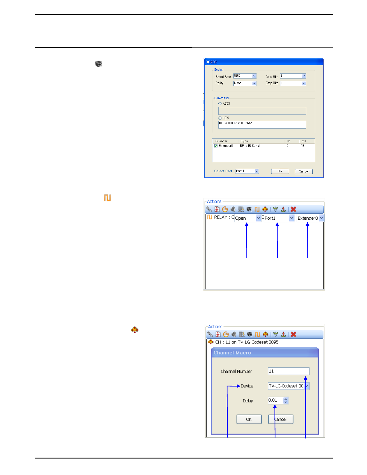
⑦ Add Relay Action( ) : To add relay action.
a. Open : To continuously connect the open relays
b. Close : To open the closed relays.
c. Trigger : To close the open relays for a
predetermined period of time. This function is
commonly used in most relay functions. 250ms is
set as default.
e. Select Port : To select the Extender Port to which
the device is connected.
f. Select Extender : To select the Extender to which
the device is connected.
d. Toggle : To toggle between relay status.
Select
Action
Select
Port
Select
Extender
⑥ Add RS Action( ) : To add RS232/485 functions.
a. Setting : Set the communication methods (such as
Baud Rate, Date Bits, Parity, Stop Bit) as same as
the controller.
b. Command : Enter the code of the button to be
controlled. Select either ASCII or HEX.
c. Select Extender: Select the Extender to which the
device is connected.
d. Select Port: Select the Port of Extender to which the
device is connected.
※ Please refer to the manufacturer‟s
information on communication methods
and control codes.
⑧ Add Channel Macro Action( ) : To enter a
particular channel globally on the device that has
numerical data (such as TV with Digit 0, Digit 1,
Digit 2 and etc)
a. Add Device to Device Library: To add devices
with numeric data, and to setup Action to such
devices, to My Database
b. Device :To select a device to control
c. Channel Number : To enter a channel number to
select
d. Delay : To set the delay time between the
numeric data during executing Macro
※ You cannot use a device that has no numeric
data.
Select
device
to
control
Enter
channel
number
Set Delay
time
Page 31
31
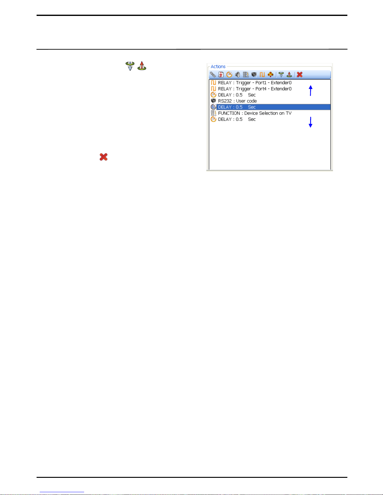
⑨ Move Down, Move Up ( , ) : To prioritize
Actions for a button with many actions.
⑩ Action Delete ( ) : To delete unwanted Actions
Move UP
Move Down
Page 32
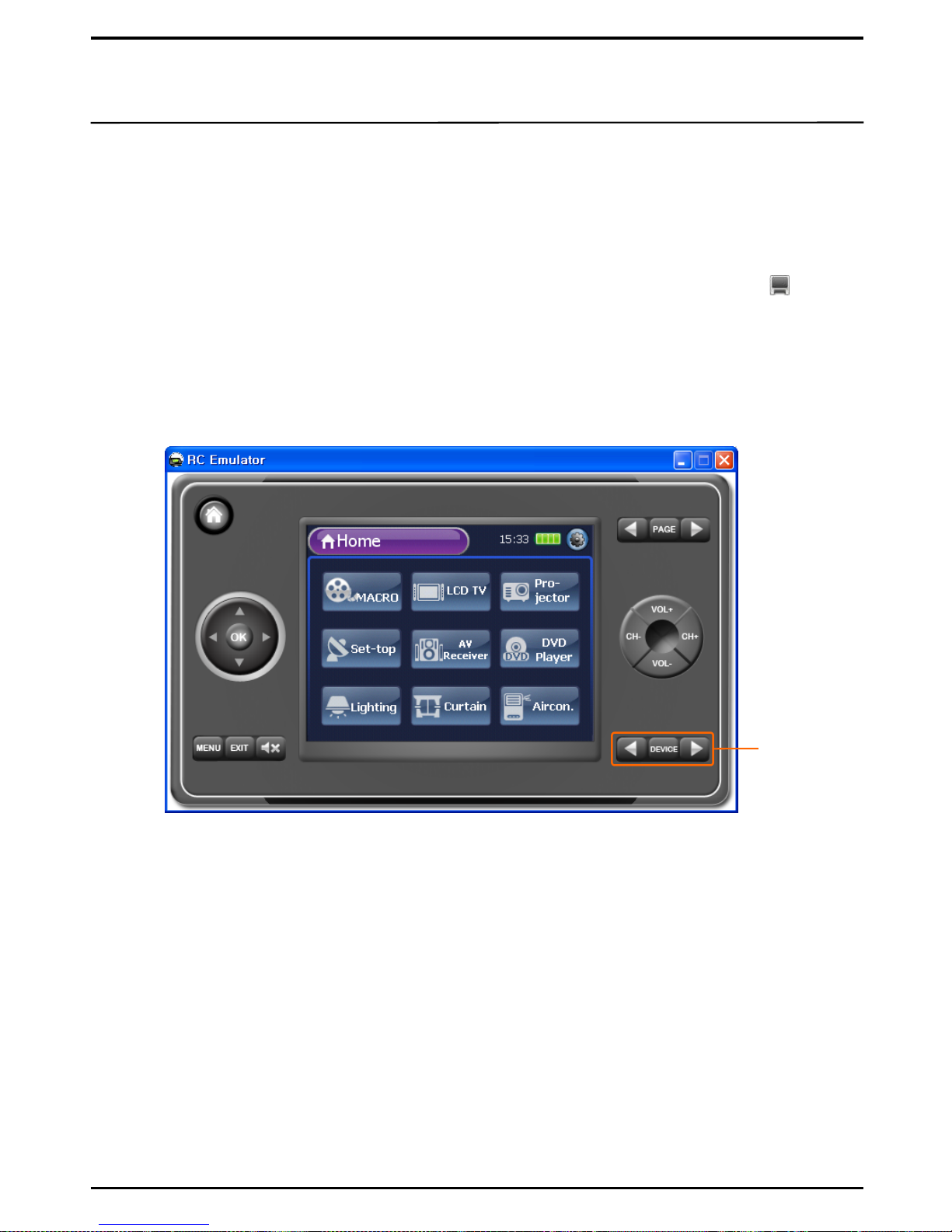
The Emulator function is used to check properties of the buttons or the screens configured on
UIPC Editor, from your PC without sending data to UX3500. Operational status of devices can also
be tested by simply connecting to UC3500 via USB.
IV. Test & Transmission
① Upon saving data which was been processed on UIPC Editor, click or Ctrl + M or the
button to execute Emulator.
② Check if data works properly once Emulator is executed. During the test, check the LCD
screen configuration and the external hard buttons also.
32
1. Emulator Test
1. To Execute Emulator
※ If data is not saved, Emulator may not work.
[Emulator Execution Screen]
External hard
buttons
① Connect UX3500 to a PC via USB.
2. Test for Device Operation
② Execute Emulator to test each of the buttons. Property of each button is delivered to UX3500
via USB so as to enable Actions.
③ If every thing works correctly, send data to UX3500.
※ Emulator saves time as it instantly enables verification of device operations and screen
configurations without sending data to UX3500.
※ The bigger the data, the longer it takes to send from the PC to UX3500.
Page 33
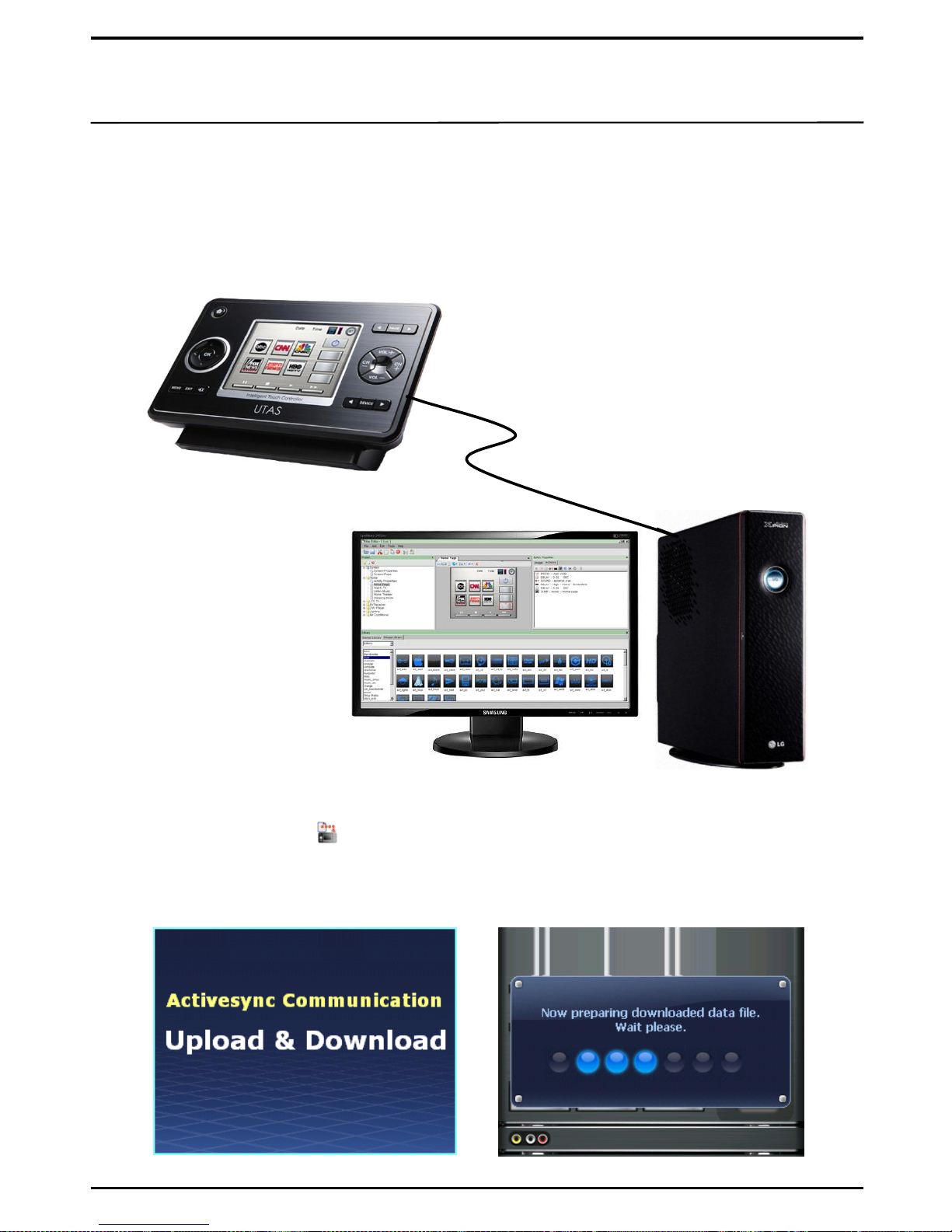
Data processed on UIPC Editor can simply be transmitted to UX3500 via an USB port. The transmission
time may vary depending on the size of data. Upon transmission, UX3500 is re-booted automatically.
[UX3500]
[USB Connection]
[UIPC Editor Screen Configuration]
① Connect to PC: To connect a PC to UX3500 using the USB cable provided with the product
② Check Active Sync: ActiveSync is automatically executed once the connection between a PC
and UX3500 is correctly made.
③ Download to UX3500 ( or Ctrl + D) : Upon data transmission from UIPC Editor, the
screen of UX3500 is changed to „Upload & Download‟.
④ Transmission Complete: Upon transmission, UX3500 is automatically re-booted and the
screen configured on UIPC Editor is shown on UX3500.
33
2. UX3500 Transmission
Page 34
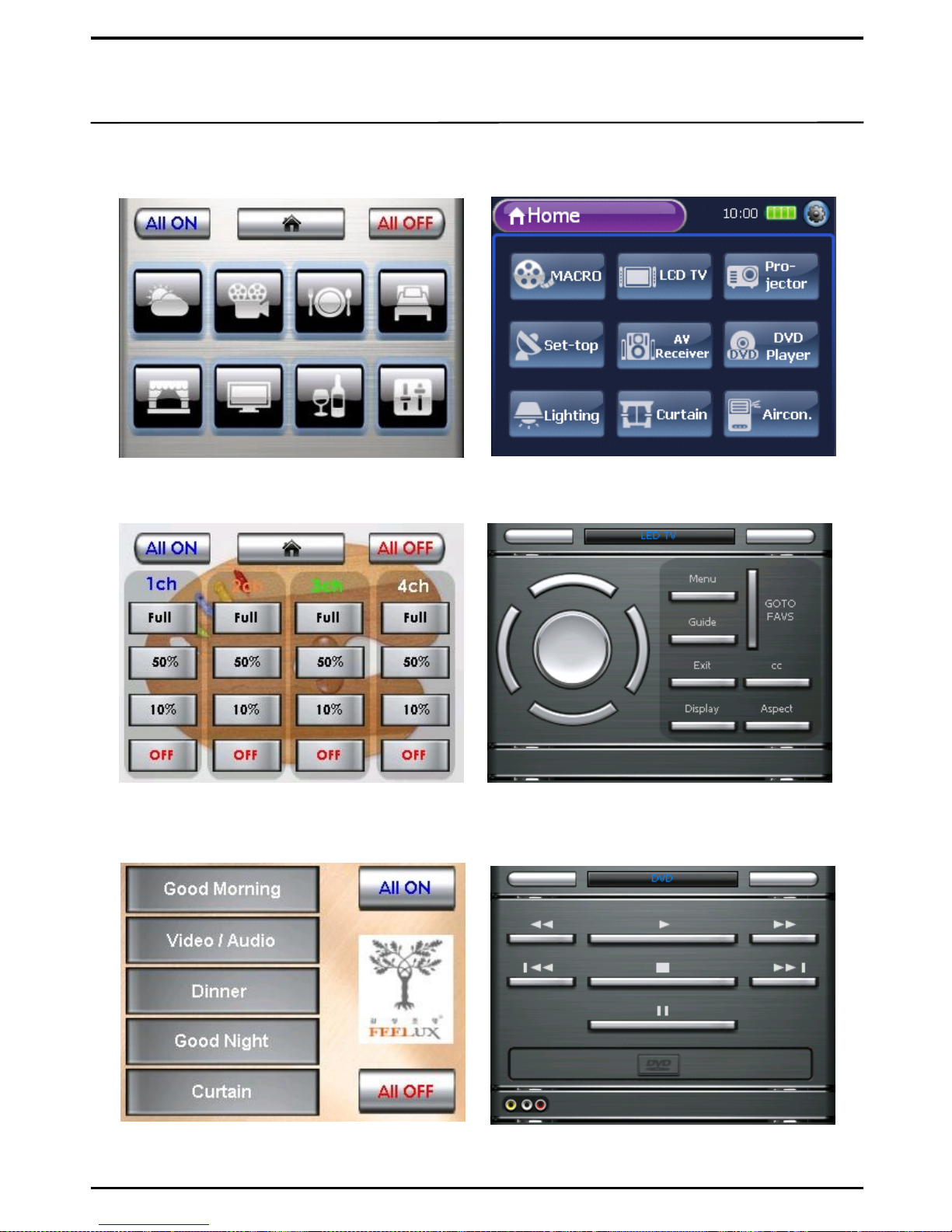
V. Examples of Screen Configuration
34
Home Page
Home Page
Lighting Dimming Control
LED TV
DVD PlayerLighting Scene Control
 Loading...