

Page 1

UTAS
www.utas.co.kr
LAN to Multi Converter
LMC100A
© 2010 UTAS Inc.
UTAS IS NOT RESPONSIBLE FOR TECHNICAL OR EDITING ERRORS IN THE CONTENTS OF THIS GUIDE. UTAS IS NOT
RESPONSIBLE FOR ANY SPECIAL, INDIRECT OR CONSEQUENTIAL DAMAGES OR ANY DAMAGES WHATSOEVER
RESULTING FROM ARISING OUT OF OR IN CONNECTION WITH THE USE OR PERFORMANCE OF DOCUMENTS, OR
LOSS OF USE.
THE CONTENTS AND INFORMATION INCLUDED IN THIS GUIDE ARE COPYRIGHT PROTECTED.
THUS, THEY CANNOT BE COPIED, REPRODUCED, OR TRANSLATED WITHOUT UTAS INC‟S WRITTEN CONSENT.
User Manual
Page 2
RF to LAN and LAN to RF Converter– LMC100A
www.utas.co.kr
1
■ Features
· Multi-zone control via network
· Setting unique IP for each LMC100A
· 2.4GHz RF(built-in Zigbee module )
. 2.4GHz external antenna (2dB )
■ Specification
· Port : 1 LAN(RJ-45), 1 RS232, 4 IR
. Radio Frequency : 2.4GHz
· Range: about 100m with 2dB antenna
· ChannelAddress : 16
· DC Power : 12V/1.5A SMPS DC Adaptor
· Plate type (Black)
■ Accessories
· 12V DC adaptor for exclusive use
※ As length of LAN cable varies
depending upon the place of
installation, it is not regarded as
one of accessories provided free of
charge. Please make it according to
site conditions or purchase it .
■ LMC100A
■ Product description
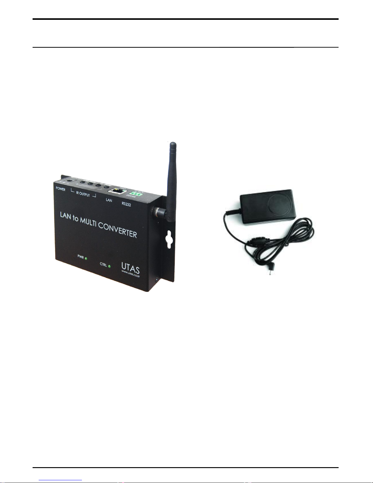
RF to LAN and LAN to RF converter – LMC100A receives RF signal transmitted from
touch panel and converts it to TCP/IP signal and then, transmits TCP/IP signal to another
LMC100A via network. LMC100A which received TCP/IP signal controls RF controller
connected with device by converting it again to RF signal.
By controlling device via network, it is capable of controlling more easily multi-zones at
various locations.
■ 12V DC Adaptor
Page 3
2
www.utas.co.kr
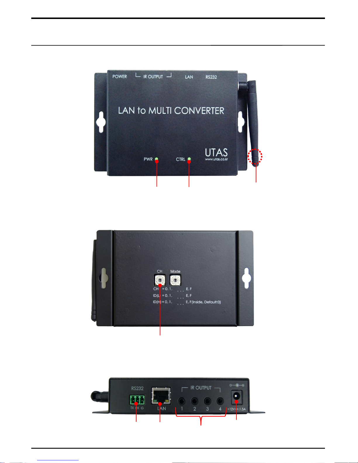
■ Front View
■ Bottom View
■ Top View
Product Kit Details
Power LED
Control LED
RF Receiver antenna
(Basically 2dB)
※ Mode conversion switch not in use
Channel Switch
Unused ports
RS232
Port
RJ-45
Port
DC Adapter power connection
(12V, 1.5A)
Page 4
LMC100A Installation – WC1000
3
■ System Configuration with WC1000 Touch Panel
■ WC1000 Network Configuration
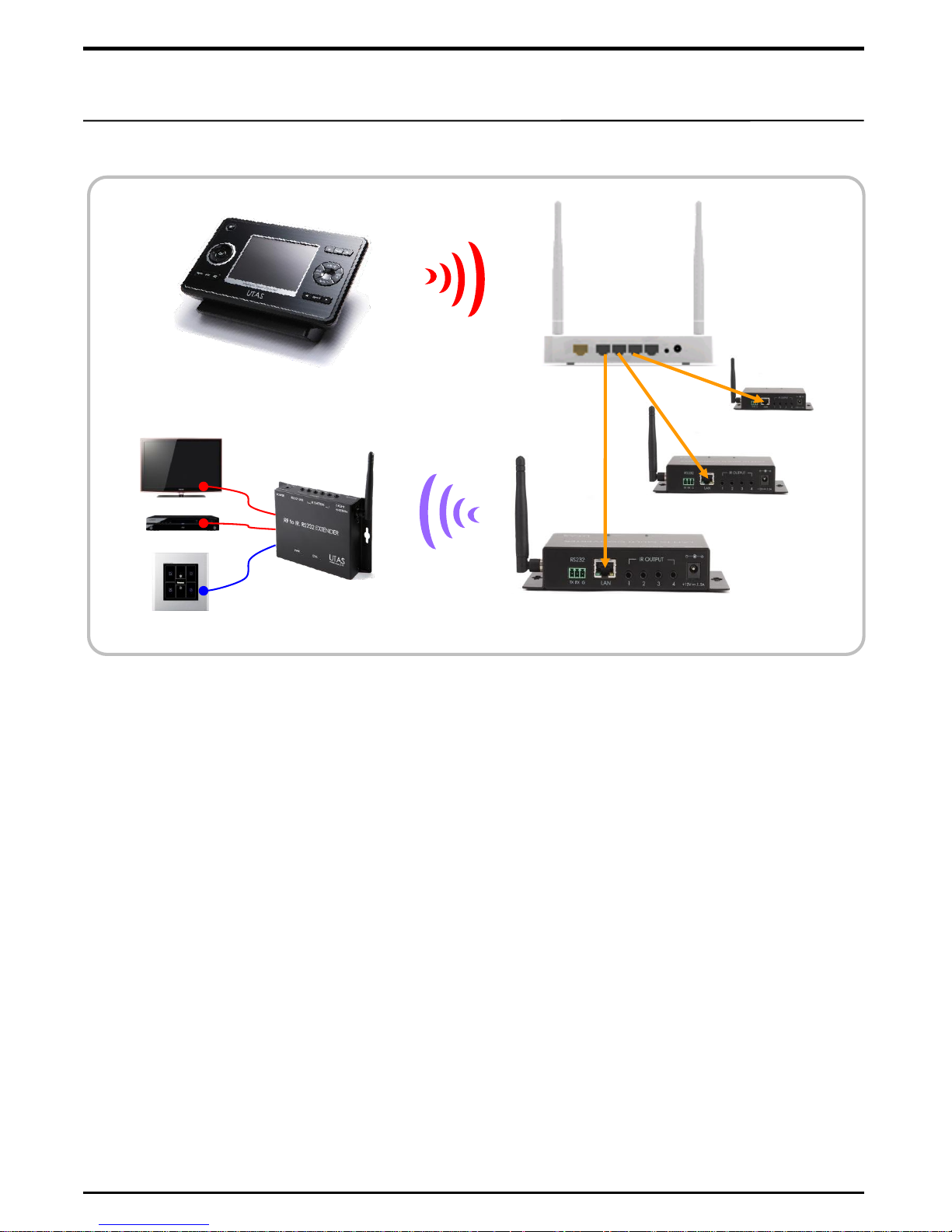
① It is the way to form the network when using WC1000 Touch Panel(Or PC Integrated
Control Program). Input IP address of LMC100A which is received the order in the
corresponding button of WC1000 in order to send the specific button's instruction to
LMC100A in the WC1000. (Refer to the WC1000 User Manual how to input)
② The instruction sent to WC1000 is delivered to LMC100A thru Wi-Fi network.
The instruction in LMC100A changes LAN to RF signal and send it to the RF controller
like IRE200A or RLE400A.
③ We call the LMC100A a 'Server' which can be used LAN to RF. You need to register the
unique local IP in each LMC100A when used a server. (Refer to the page 7 for registering)
④ To use LMC100A, the location where it is to be installed needs to consist of one network.
In other words, total system needs to be interconnected using one IP Router.
⑤ As there are four LAN ports in one basic IP Router, one Router can control 4 multi-zones.
To control more than 4 multi-zones, LAN ports need to be increased using switch herb.
⑥ As many LMC100A can be installed as number of IP. As IP Router basically supports
about 200 IPs, LMC 100A can control about same number of IPs with networks.
www.utas.co.kr
WC1000
Wi-Fi
Server
LMC100A
RF Signal
LAN Cable
RF Controller
Wi-Fi
Router
LMC100A
in other place
Page 5
4
■ RF Touch Panel Network Configuration
■ LAN Cable
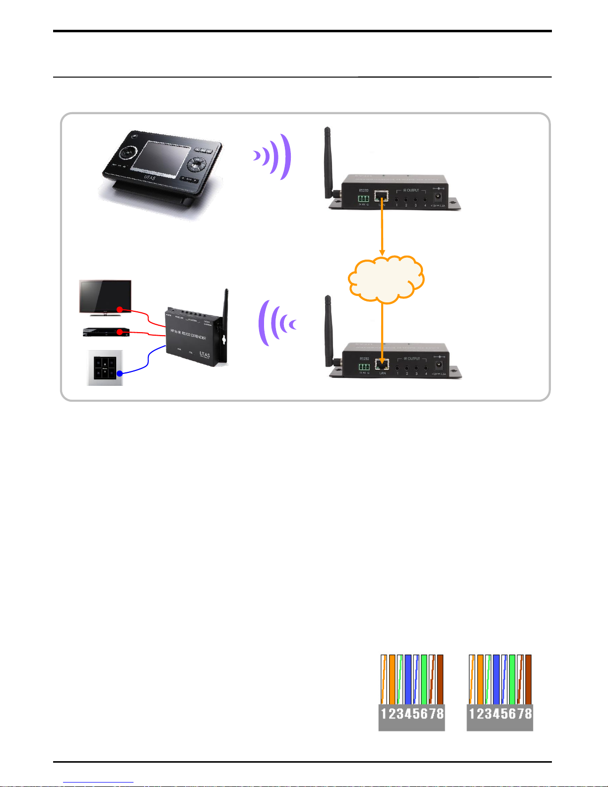
Arrangement Sequence
of Direct LAN cable
① LAN cable is manufactured to the length of a location
where it is installed using RJ-45 jack and 4 pairs of
UTP cable.
② LAN cable uses direct cable.
① It is the way to send the RF signal of touch panel like UX3500 or ITRC8500DX as far as
possible.
② We call the LMC100A a 'Client' which can change RF signal to LAN. 'Client' and 'Server'
communicate one to one. When inputting the local IP of 'Server' in the 'Client', the
instruction can be sent to 'Server'. (Refer to the page 8 of "How to set IP")
③ You need to set up RF touch panel, LMC100A for 'Client' and RF controller the same
channel. The channel setup switch for LMC100A is located at the bottom of it.
Note 1. No need to set up the channel for LMC100A for using a 'Server'.
2. Refer to the corresponding manual for setting up of touch panel and RF controller.
④ To use LMC100A, the location where it is to be installed needs to consist of one network.
In other words, total system needs to be interconnected using one IP Router.
Touch Panel
RF Signal
Client
LMC100A
(RF to LAN)
Server
LMC100A
(LAN to RF)
RF Signal
LAN Cable
LAN Cable
RF Controller
TCP/IP
Network
www.utas.co.kr
■ System Configuration with RF Touch Panel
LMC100A Installation – RF Touch Panel
Page 6
5
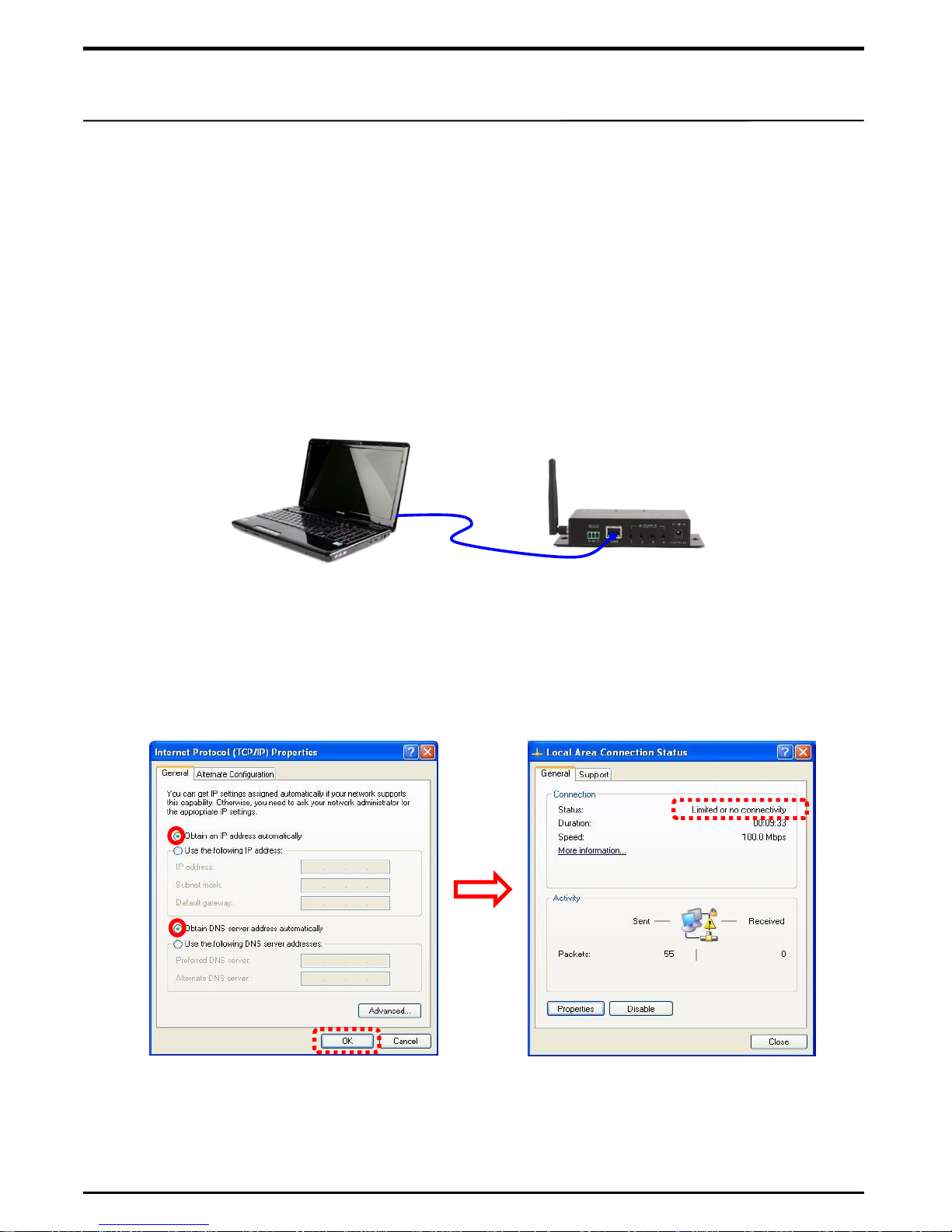
■ Connection with PC for IP setting
① To set IP of LMC100A, PC(or Notebook PC) and LMC100A are to be interconnected
via LAN port .
② After having network TCP/IP setting in PC in automatic mode, press <OK>, then
automatic searching for IP starts. As IP can not be found while being connected with
LCM100A, a message appears saying “Limited or no connectivity” in 1~2 minutes.
It is in a normal course of procedure.
③ When connection between PC and LMC100A is complete, IP of LMC100A is set
through IP setting program.
LMC100A – IP Setting
UTP Cable (Direct)
■ LMC100A - IP
IP of LMC100A means an internet address of LMC100A. As instructions are delivered to
given IP address via network, each LMC100A needs to have an unique IP. We call this
unique IP for 'Local IP'. Also you need to input Gateway and Subnet address accurately
like Local IP. Please note that this is a concept different from RF CH setting at bottom
part of the product.
www.utas.co.kr
TCP/IP setting screen
Networking connection
Page 7
6
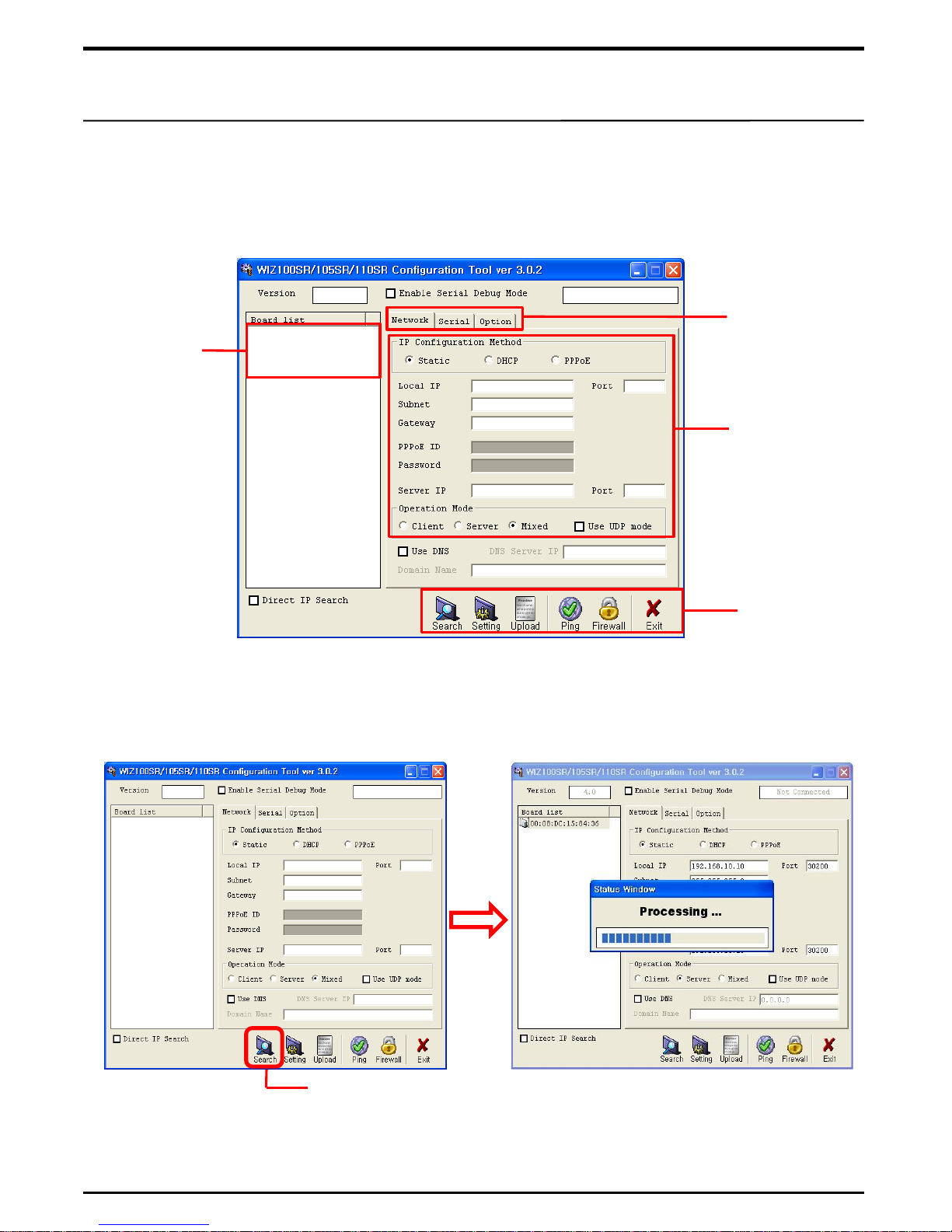
■ WIZnet Configuration Tool
① Install „WIZ1XXSR Configuration Tool‟, a program to set LMC100A IP, in a PC.
Note. „WIZ1XXSR Configuration Tool‟ is inside of CD which is provided with LMC100A.
② After executing the program, press „Search‟ button to start searching in LMC1000A.
③ When a message „Complete searching‟ appears, press „Close‟ button.
LMC100A – IP Setting Program
WIZnet Configuration Tool
MAC
address
window
Setting
Menu
LMC100A
IP setting
window
Program
Menu
www.utas.co.kr
Search Button
Page 8
7
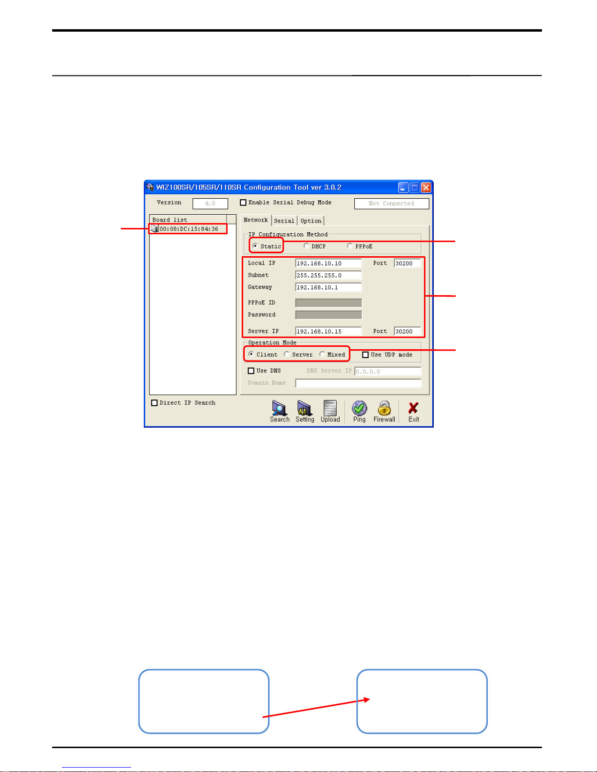
① Board List : A window where unique MAC address of LMC100A appears. As MAC
address, not like IP address, is a fixed value not subject to change, it will be useful
later to manage after installation when you take a note of it together with IP address.
LMC100A – How to set IP
■ Names of each segment of program and how to set
② IP Configuration Method : Select IP Configuration Method. Check LMC100A in
Static Method. DHCP and PPPoE are not used.
③ Local IP : A unique IP address of LMC100A. It should be set not to be duplicated
with other LMC100A IP address. Enter port No. 30200 of LMC100A in Port section.
④ Subnet : Enters Router‟s Subnet address.
⑤ Gateway : Enters Router‟s Gateway address.
⑥ PPPoE ID and Password are not used.
⑦ Server IP : Enters IP address of Destination to which instruction will be delivered.
When LMC100A is used as Client and Mixed, make sure that it be entered. When it is
used as Server, enter 0. 0. 0. 0 as there is no need for IP address of destination in
LMC100A. Enter No. 30200 in Port section.
Client LMC100A
Local IP : 192.168.0.10
Server IP : 192.168.0.15
Server LMC100A
Local IP : 192.168.0.15
Server IP : 0. 0. 0. 0
www.utas.co.kr
IP Setting Screen
Check
Static
IP Address
Setting
Operation
Mode Setting
MAC
address
Page 9
8
⑧ Operation Mode : Sets operation mode of LMC100A.
a. Client : Selected when LMC100A is used for RF to LAN. Used as a role in transmitting
LAN signal to server. At this time, make sure that Local IP and Server IP be entered.
b. Server : Selected when LMC100A is used for LAN to RF. Used as a role in receiving
LAN signal from Client. At this time, enter exact Local IP address.
c. Mixed : Selected when role of both Client and Server is to be played concurrently.
As it may transmit or receive LAN signal, enter Server IP address in same way as
when Client is set. (Recommendable that Client and Server be used separately for
accurate signal communication)
LMC100A – How to set IP
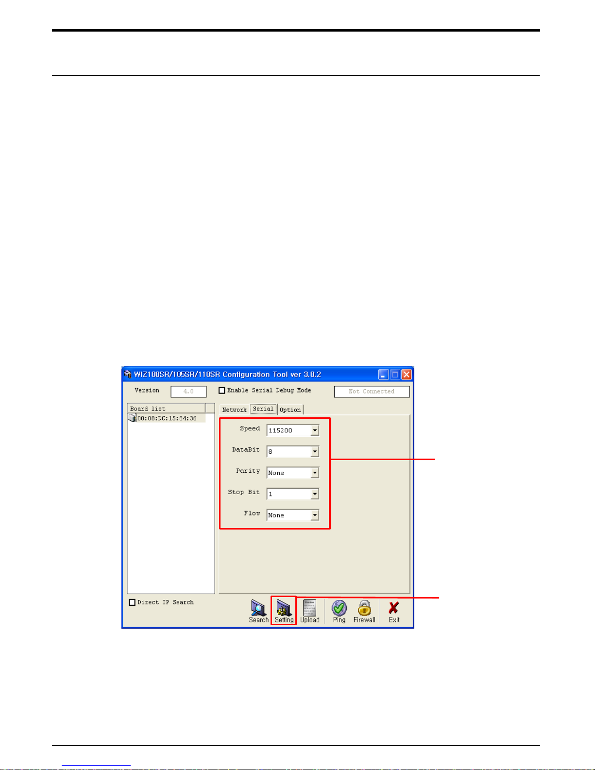
⑨ Serial : Sets communication speed of WIZnet chipset and RF module in LMC100A.
a. Speed : Basic communication speed is 115200 bps. Though in some cases, 57600
bps or 38400 bps are used, it is set at default value of 115600 bps.
b. DataBit, Parity, Stop bit, Flow : It is set at default value of 8, None, 1, None as
shown in the picture.
Note. When Serial port of LMC100A is used to control directly for Serial equipment,
make sure that communication speed of the equipment be entered.
⑩ Option : Option setting is used only when packet does not communicate normally
in case „Serial communication speed‟ changes. It is not used in other cases.
Serial
Communication
speed setting
Setting Button
www.utas.co.kr
Page 10
9
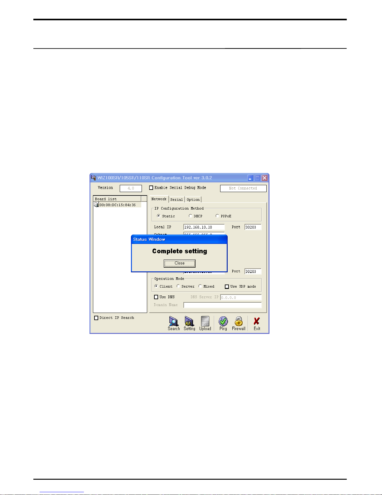
⑪ Setting : When all settings are done, Press „Setting‟ button at the bottom to register
data set in LMC100A. After „Processing…‟ bar passed by, „Complete setting‟ window
appears, then press „Close‟ button. If above process done, IP setting for LMC100A is
done.
LMC100A – Completion of IP Setting
Note 1. If „Fail to set‟ window appears, it means that PC does not communicate with
LMC100A. Check communication cable and connection port to find if connection
is made appropriately.
2. For detailed explanation about this program, refer to product manual provided in
www.wiznet.co.kr.
■ Connection with Router or Switch Hub
Once setting is done for LMC100A, connect the LMC100A with Router or Switch Hub
using corresponding Gateway address. One can check IP address of the Router in the
PC connected with the Router. Regarding „how to set a Router‟, refer to „how to set IP
Router‟ as attached.
www.utas.co.kr
■ Communication with Touch Panel
To enable Touch Panel to communicate with LMC100A(RF to LAN), both RF „CH‟
transmitted from touch panel and RF „CH‟ switch at the bottom of LCM100A are to be
equally set.
Page 11
1
※ Annex – How to set IP Router
■ Identification of Gateway address of IP Router
This pertains to how to set IP Router(hereinafter referred to as Router) to be used in
connection with LMC100A. Same Gateway and Subnet address used in Router is
likewise used in LMC100A. If a connection is made with LMC100A via outside internet,
port forward of Router is to be set. One can confirm such setting in PC connected with
Router.
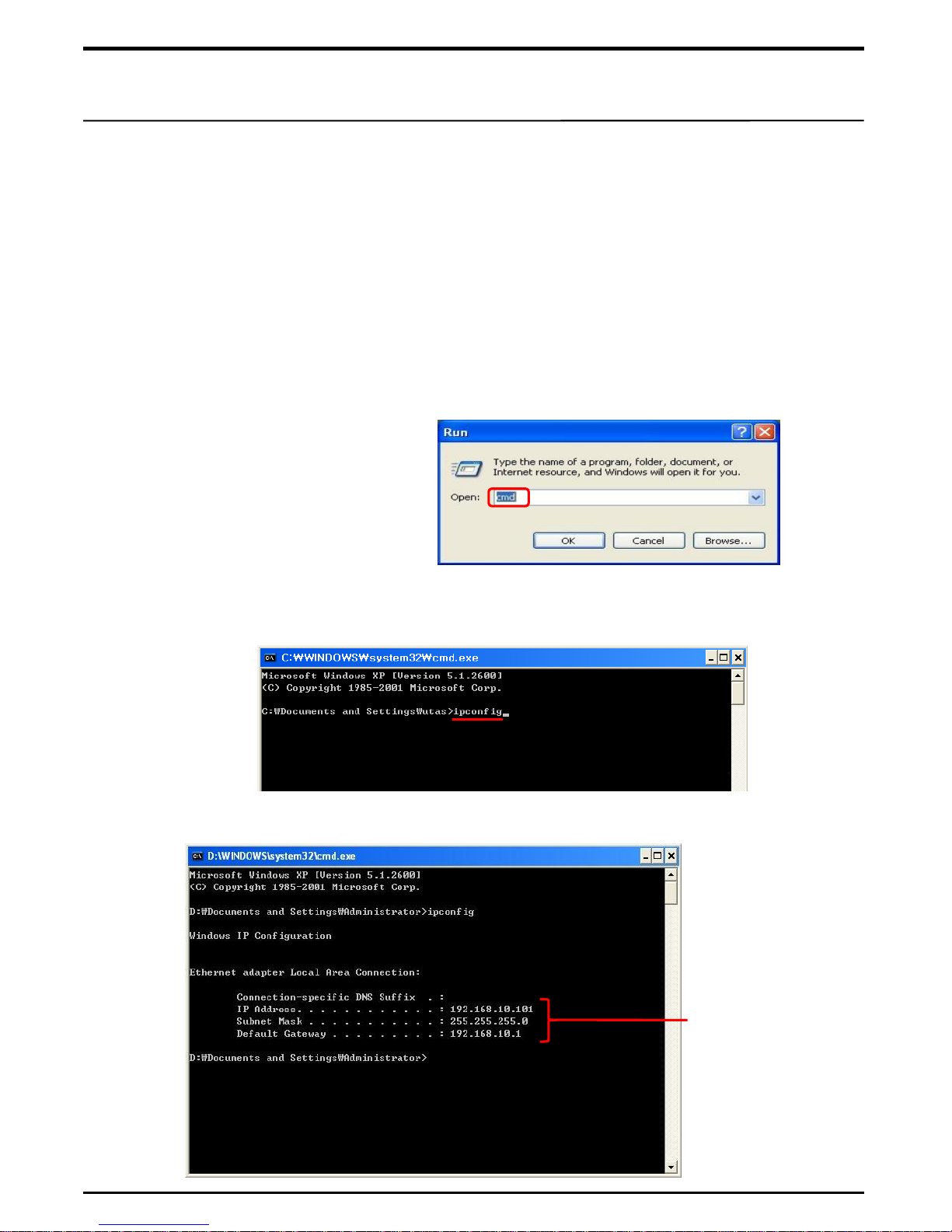
① IPCONFIG : Pertains to how to identify IP address of Router in PC.
a. CMD : After selecting „Execution(R)‟ in „Start‟ menu in PC, enter an instruction „CMD‟
and press <OK>.
b. IPCONFIG : When the below window appears, enter instruction „ipconfig‟ and
press <ENTER> key.
C. Check if the below IP information of Router appears.
www.utas.co.kr
IP information of
Router connected
with PC
Page 12
2
■ IP Router setting
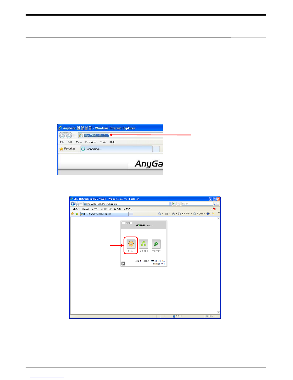
① After executing an Internet Explorer, input previously confirmed Gateway address of
Router in address window and press <ENTER> key.
② When the below Router setting screen appears, select „Administration Tool‟.
Administration
Tool
Note. The Router setting screen varies depending upon manufacturer and model of
Router. This manual is based on basic Router setting method. Detailed menu or
setting method other than basics varies from manufacturer to manufacturer.
Regarding detailed Router setting method, refer to Router manual in use.
② Identification of Gateway address : When IP information of Router appears,
identify Gateway address. If the address is shown as 0 . 0 . 0 . 0 , a PC remains
unconnected with Router. After checking how PC is connected with Router, execute
above processes again.
www.utas.co.kr
※ Annex – How to set IP Router
Inputting Gateway
Address of Router
Page 13
3
■ Router - Internal network setting
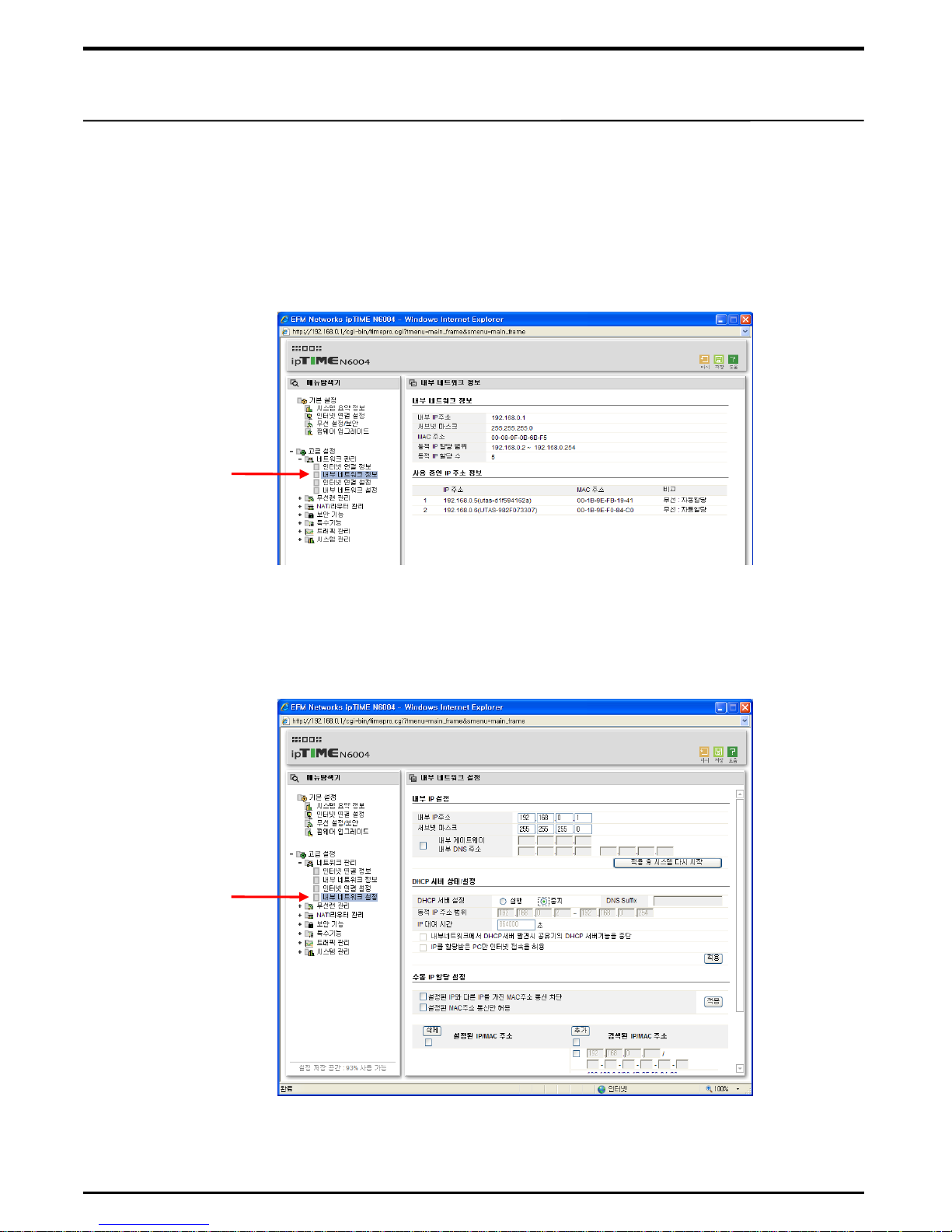
① Check „internal network information‟ in professional settingin an „administration tool‟
of a Router. „IP allocation range‟ is a range of IP which can be set in its
corresponding Router. When Local IP of LMC100A is registered, IP needs to be
input in a range given.
② In „internal network setting‟, click on <STOP> in „DHCP server setting‟ and then,
click on <OK> to save.
Note. Please note that internal network IP is different from external IP connected with internet.
Note. Most of Routers‟ internal IP address are set at „192.168. 0. 1‟. If you want to change it,
enter new IP address in „internal IP setting‟ entry, then click on <OK> to save.
www.utas.co.kr
Internal
Network
Information
Internal
network
setting
※ Annex – How to set IP Router
Page 14
4
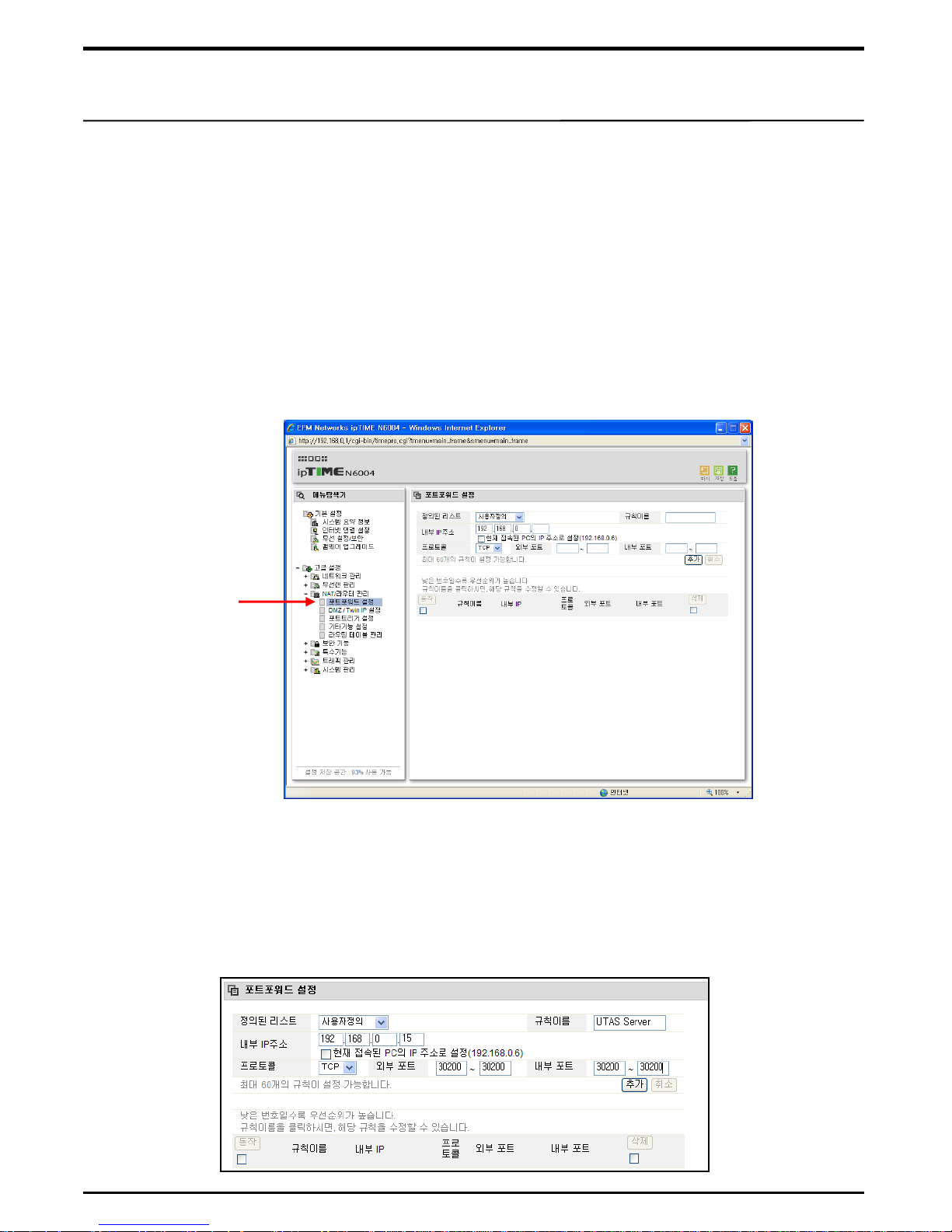
■ Router - Port forward setting
Port forward refers to pre-setting a port so that when signal transmitted via external
internet is reforwarded to internal IP of Router, the signal can be sent to designated
internal IP address. Port forward setting is required only to control LMC100A used as
a server in an external internet. As UTAS uses Port No. 30200, No. 30200 is to be
designated for port to be registered at a time of port forward setting.
① Select „port forward setting‟ in NAT/Router administration menu of professional
setting entry.
② In defined list, select „USER DEFINITION‟ and enter name of IP for registration in
regulation name entry. e.g. UTAS, Server 1 etc.
③ Enter internal IP address used in LMC100A intended for Server.
④ Select TCP for protocol and enter No. 30200 both for external and internal port.
www.utas.co.kr
Port forward
※ Annex – How to set IP Router
Page 15
5
■ Setting PC connected with a Router
If an internet is used with a Router in connection with an external IP, it is recommended
that the IP of PC connected with the Router be permanently registered. Have IP
address no longer used in LMC100A permanently registered in PC. Be careful that if
an IP address assigned in LMC100A happens to be registered in IP, two same IPs
may conflict.
Note. With IP of PC in automatic operation mode, PC searches for an unassigned IP.
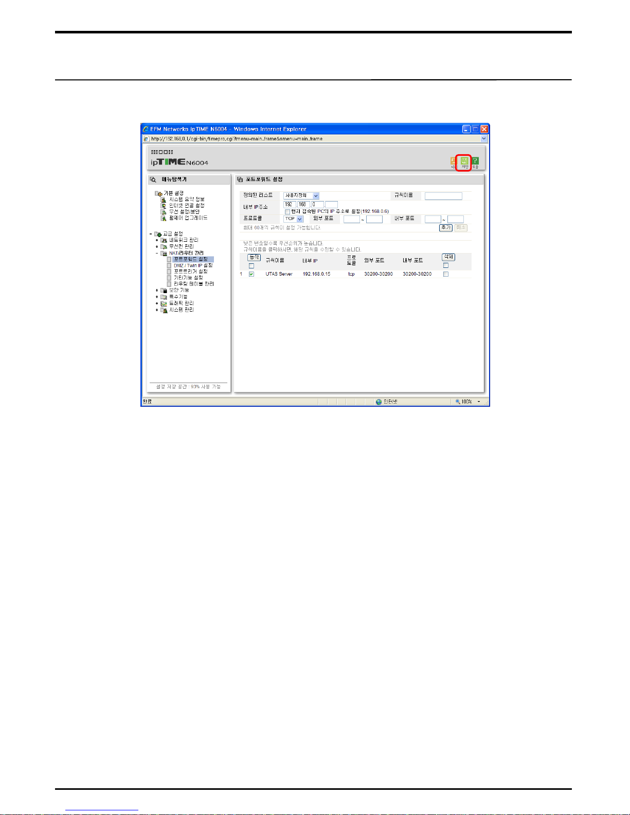
⑤ Click on <ADD> to save what has been registered.
⑥ When all settings are done, press <SAVE> button to save them.
www.utas.co.kr
※ Annex – How to set IP Router
 Loading...