

Page 1
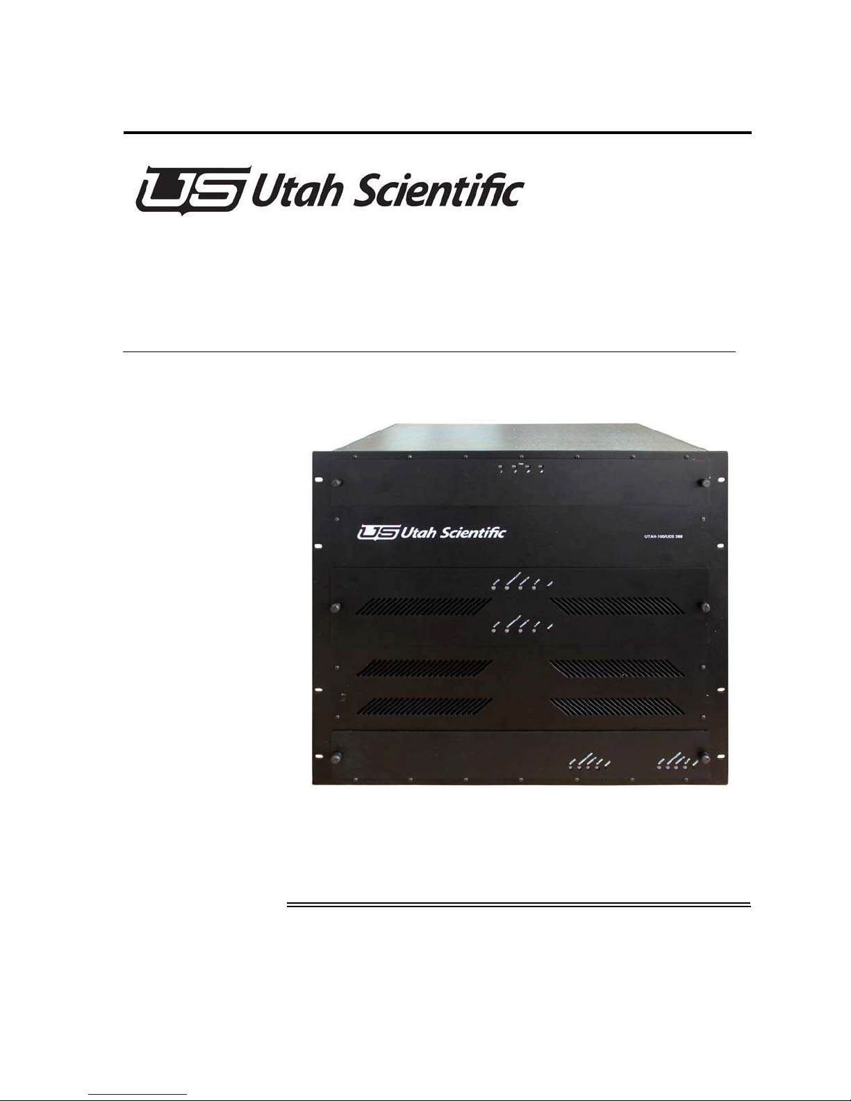
UTAH-100/UDS 288
System Setup and Operation Guide
Page 2

UTAH 100/UDS 288x288 Operations Guide
• Document Number: 82102-0079
• Document Version: 1.3
• Date: March 21, 2016
• Printed in U.S.A.
Copyrights and Trademarks
© 2016 Utah Scientific, Inc., All rights reserved. Any use or reproduction of this
guide’s contents without the prior written consent of Utah Scientific, Inc. is
strictly prohibited.
• UTAH 100 is a trademarks of Utah Scientific, Inc.
• Windows, Windows 2000 and Windows NT and XP are registered trademarks
of Microsoft Corporation.
• All other product names and any registered or unregistered trademarks men-
tioned in this guide are used for identification purposes only and remain the
exclusive property of their respective owners.
Notice
Information contained in this guide is subject to change without notice or
obligation. While every effort has been made to ensure that the information is
accurate as of the publication date, Utah Scientific, Inc. assumes no liability for
errors or omissions. In addition, Utah Scientific, Inc. assumes no responsibility
for damages resulting from the use of this guide.
FCC Compliance (USA) and Digital Equipment Compliance (Canada)
This equipment has been tested and found to comply with the limits for a Class
A, digital device, pursuant to Part 15, Subpart B of the FCC Rules and the
Canadian EMC Requirement (ICES-003). These limits are designed to provide
reasonable protection against harmful interference when the equipment is
operated in a commercial environment. This equipment generates, uses, and can
radiate radio frequency energy and, if not installed and used in accordance with
the instruction manual, may cause harmful interference to radio communications.
ii
Page 3

Operation of this equipment in a residential area is likely to cause harmful
interference, in which case, the user will be required to correct the interference at their
own expense. Shielded cables must be used to ensure compliance with the FCC Class
A limits.
Section 1
iii
Page 4
Declaration of Conformity
Utah Scientific, Inc.
4750 Wiley Post Way, Suite 150
Salt Lake City, Utah 84116-2878 U.S.A.
We declare our sole responsibility that the UTAH-100/UDS Digital Routing
Switcher is in conformance with the following standards:
Emission
• EN55022:1994+A1&A2
Immunity
• EN55024:1998
• EN61000-3-2
• EN61000-3-3
Safety
• IEC 60950-1:2001 /EN 60950-1:2001
Following the provisions of the Directive(s) of the Council of the European
Union:
• EMC Directive 89/336/EED
• Low Voltage Electrical Directive 72/23/EEC
Utah Scientific, Inc. hereby declares that the product specified above conforms to
the above Directive(s) and Standard(s).
iv
Page 5
Important Safeguards and Notices
This section provides important safety guidelines for the Operator and Service
Personnel. Specific warnings and cautions are found throughout the guide where they
apply, but may not appear here. Please read and follow the important safety
information, specifically those instructions related to risk of fire, electric shock, or
injury to persons.
Safety Symbols
•Hazardous Voltage symbol
•Caution symbol. The product is marked with this symbol
when it is necessary to refer to the manual to prevent damage
to the product.
Warnings
Please observe the following important warnings:
•Any instructions in this guide that require opening the chas-
sis, changing a power supply, or removing a board, should be
performed by qualified personnel only. To reduce the risk of
electric shock, do not perform any service unless you are
qualified to do so.
•Heed all warnings on the unit and in the operating instruc-
tions.
•Do not use this product in or near water. Disconnect AC
power before installing any options or servicing the unit
unless instructed to do so by this manual.
•This product is grounded through the power cord ground con-
ductor. To avoid electric shock, plug the power cord into a
properly wired receptacle before connecting the product
inputs or outputs.
•Route power cords and other cables so they won’t be dam-
aged.
•The AC receptacle (socket) should be located near the equip-
ment and be easily accessible.
•Disconnect power before cleaning. Do not use any liquid or
aerosol cleaner - use only a damp cloth.
Section 1
v
Page 6
•Dangerous voltages exist at several points in this prod-
uct. To avoid personal injury, do not touch exposed conductors and components while power is on. Do not insert
anything into either of the systems two-power supply
cavities with power connected.
•Do not wear hand jewelry or watches when troubleshoot-
ing high current circuits, such as power supplies. During
installation, do not use the door handles or front panels
to lift the equipment as they may open abruptly and
injure you.
•To avoid fire hazard when replacing fuses, use only the
specified correct type, voltage and current rating as referenced in the appropriate parts list for this product.
Always refer fuse replacement to qualified service personnel.
•Have qualified personnel perform safety checks after any
service.
Cautions
Please observe the following important cautions:
•When installing this equipment do not install power
cords to building surfaces. To prevent damage when
replacing fuses, locate and correct the problem that caused
the fuse to blow, before reconnecting power.
•Use only specified replacement parts
vi
Page 7

Company Information
Utah Scientific, Incorporated
4750 Wiley Post Way, Suite 150
Salt Lake City, Utah 84116-2878 U.S.A.
• Telephone: +1 (801) 575-8801
• FAX: +1 (801) 537-3098
• Technical Services (voice): +1 (800) 447-7204
• Technical Services (FAX): +1 (801) 537-3069
• E-Mail -General Information: [email protected]
• E-Mail -Technical Services: [email protected]
• World Wide Web: http://www.utahscientific.com
• After Hours Emergency: +1 (800) 447-7204. Follow the menu instructions for
Emergency Service.
Section 1
vii
Page 8

Warranty Policies
Hardware Warranty
Utah Scientific, Inc. warrants to the original purchaser that the Utah
Scientific hardware is free from defects in materials and workmanship
and will perform substantially in accordance with the accompanying
written materials under normal use and service for a period of two (2),
five (5), or ten (10) years from the date of shipment. Any implied
warranties on hardware are limited to the above three warranty periods
(depending on purchase). Some states/jurisdictions do not allow
limitations on duration of an implied warranty, so the above limitation
may not apply to certain specific purchasers.
Software Warranty
Utah Scientific warrants that the software will perform substantially in
accordance with the accompanying written materials for a period of one
(1) year from the date of shipment.
Customer Remedies
For the first one (1) year after purchase of the software and the first two
(2), five (5), or ten (10) years after the date of purchase of the hardware,
Utah Scientific’s and its suppliers’ entire liability and purchaser’s
exclusive remedy shall be, at Utah Scientific’s option, either:
• Return of the price paid, or
viii
• Repair or replacement of the software or hardware
that does not meet the above warranties and is
returned to Utah Scientific under the returned
materials authorization (RMA) process with freight
and forwarding charges paid.
After the initial warranty periods, purchaser’s exclusive remedy is the
repair or replacement of the hardware upon payment of a fixed fee to
cover handling and service costs based on Utah Scientific’s then-current
price schedule. The above warranties are void if failure of the software
or hardware has resulted from an accident, abuse, or misapplication.
Any replacement software or hardware will be warranted for the
remainder of the original warranty period or thirty (30) days, whichever
is longer.
Page 9

No other warranties. To the maximum extent permitted by applicable law,
Utah Scientific and its suppliers disclaim all other warranties, either express
or implied, including, but not limited to implied warranties of
merchantability and fitness for a particular purpose, with regard to the
software, the accompanying written materials, and any accompanying
hardware. This limited warranty gives the purchaser specific legal rights.
These rights may vary in certain states/jurisdictions.
No liability for consequential damages. To the maximum extent permitted
by applicable law, in no event shall Utah Scientific or its suppliers be liable
for any damages whatsoever (including without limitation, damages for loss
of business profits, business interruption, loss of business information, or
any other pecuniary loss) arising out of the use of or inability to use Utah
Scientific products, even if Utah Scientific has been advised of the
possibility of such damages. Because some states/jurisdictions do not allow
the exclusion or limitation of liability for consequential or incidental
damages, the above limitation may not apply in those circumstances.
Section 1
ix
Page 10

x
Page 11

Table of Contents
Section 1
System Setup
Introduction ........................................................................... ......................... 1-1
Control System ..................................................................... ......................... 1-2
Router Hardware Description ............................................... ......................... 1-3
3G/12G .............................................................................................. 1-4
Signal Levels ............................................................................................ 1-5
Hardware Installation ............................................................ ......................... 1-6
Initial Inspections ...................................................................................... 1-6
Before Applying Power ...................................................................... 1-6
Service ............................................................................................... 1-6
Initial Setup ............................................................................................... 1-7
Installation ............................................................................ ......................... 1-8
288x288 UDS System .............................................................................. 1-8
Contents ............................................................................................ 1-9
Rear Panel Considerations ...................................................................... 1-10
MX Bus .............................................................................................. 1-10
Dip Switches ...................................................................................... 1-10
Video Ref ........................................................................................... 1-10
Power Supplies ........................................................................................ 1-11
Connecting and Disconnecting Power ............................................... 1-11
Determining and Setting Router Signal Levels ......................................... 1-12
Switch Settings ......................................................................................... 1-13
Connecting Cables ................................................................................... 1-17
Video Cables ..................................................................................... 1-17
MX Bus Cables .................................................................................. 1-17
UDS288 Crosspoint Card – 121414-1 ...................................................... 1-18
General .............................................................................................. 1-18
Circuit Description ............................................................................. 1-18
Controls and Indicators ...................................................................... 1-19
UDS288 Frame Controller ........................................................................ 1-20
Overview ............................................................................................ 1-20
Circuit Description ............................................................................. 1-20
UDS288 Frame Controller ................................................................. 1-21
UDS288 FCM Field Software Update ...................................................... 1-22
Coax Input Card 121415-1 (up to 12G) .................................................... 1-23
General .............................................................................................. 1-23
Circuit Description ............................................................................. 1-23
Table of Contents i
Page 12

Controls and Indicators ...................................................................... 1-23
Coax Input Card 121415-2 (up to 3G) ...................................................... 1-24
General .............................................................................................. 1-24
Circuit Description ............................................................................. 1-24
Controls and Indicators ...................................................................... 1-24
Coax Output Card 121416-1 (up to 12G) ................................................. 1-25
General .............................................................................................. 1-25
Circuit Description ............................................................................. 1-25
Coax Output Card 121417-1 (up to 3G) ................................................... 1-26
General .............................................................................................. 1-26
Circuit Description ............................................................................. 1-26
Section 2
Network Configuration
Introduction ........................................................................... ......................... 2-1
System Setup Requirements ................................................ ......................... 2-2
UTAH-100/UDS Network Configuration ............................... ......................... 2-3
New Configuration on Independent Network ........................................... 2-3
Router Applet Activation and Configuration ......................... ......................... 2-9
Panel Applet Activation and Configuration ........................... ......................... 2-12
Section 3
The Router Applet
Router Configuration ............................................................ ......................... 3-1
Security .................................................................................................... 3-3
Data Comm .............................................................................................. 3-4
TCP RCP-3 (Network) ....................................................................... 3-4
Serial RCP-1 ...................................................................................... 3-4
DHCP ................................................................................................ 3-5
Sources ............................................................................................. 3-6
Destinations ....................................................................................... 3-10
Destination Creation from Within the List .......................................... 3-12
Panel Views ....................................................................................... 3-14
Sorting Option .................................................................................... 3-15
Destination Blocks ............................................................................. 3-18
Salvos ................................................................................................ 3-19
Accounts ............................................................................................ 3-22
ii UTAH-100/UDS Setup & Operations Guide
Page 13

Save Button .............................................................................................. 3-24
Router Control ...................................................................... ......................... 3-25
Source and Destination Management ...................................................... 3-25
Preset (checkbox) .............................................................................. 3-28
Changing the Button Color Scheme .................................................. 3-30
Destination Reset Mode (checkbox) .................................................. 3-31
Multiple Destination Selection ........................................................... 3-31
Audio ................................................................................................. 3-32
Macro buttons .................................................................................... 3-32
Salvos ....................................................................................................... 3-34
Preset List Window ................................................................................... 3-35
Section 4
The Control Applet
Introduction ........................................................................... ......................... 4-1
The UTAH-100/UDS CP ....................................................... ......................... 4-2
Front View ................................................................................................ 4-2
Rear View ................................................................................................. 4-2
Setup ........................................................................................................ 4-2
Panel Configuration .............................................................. ......................... 4-3
System ..................................................................................................... 4-5
Network .................................................................................................... 4-5
Network Parameters .......................................................................... 4-6
Encoding .................................................................................................. 4-6
Panel Layout - Config Controls ................................................................ 4-7
Layouts - Single and Multi-Dest ............................................................... 4-9
Single Destination .............................................................................. 4-9
Multi-Dest layout ................................................................................ 4-10
XY-32 Configuration ................................................................................. 4-11
Print Option .............................................................................................. 4-14
Control Panel ........................................................................ ......................... 4-15
Table of Contents iii
Page 14

Section 5
Specifications
Frame Specifications ............................................................ ......................... 5-1
Width ........................................................................................................ 5-1
Depth ........................................................................................................ 5-1
Sizes ........................................................................................................ 5-1
Power Supply ........................................................................................... 5-2
AC Input Specifications ..................................................................... 5-2
DC output specifications .................................................................... 5-2
Control Connections: RJ-45 Ethernet ...................................................... 5-2
I/O Module Specifications ..................................................... ......................... 5-3
Multi-Rate Digital Input Card .................................................................... 5-3
Multi-Rate Digital Output Card ................................................................. 5-3
Digital Video ............................................................................................. 5-4
Control ...................................................................................................... 5-5
Alarms ...................................................................................................... 5-5
Physical .................................................................................................... 5-6
Determining and Setting Router Signal Levels ........................................ 5-8
Switch Settings ......................................................................................... 5-9
Addendum A
RCP1 Protocol for UDS
Matrix Refresh Report Enable .............................................. ......................... A-1
Matrix Refresh Report Disable ............................................. ......................... A-1
Matrix Change Report Enable .............................................. ......................... A-2
Matrix Change Report Disable ............................................. ......................... A-2
Matrix Take Report Enable ................................................... ......................... A-3
Matrix Take Report Disable .................................................. ......................... A-3
Matrix Section Refresh ......................................................... ......................... A-3
Matrix Take Command ......................................................... ......................... A-4
CALCULATE <Checksum> .................................................. ......................... A-5
MISC items ........................................................................... ......................... A-5
iv UTAH-100/UDS Setup & Operations Guide
Page 15

Addendum B
System Update
Introduction ........................................................................... ......................... B-1
System Setup Requirements ................................................ ......................... B-2
Settings File Update ............................................................. ......................... B-2
Updating the Router Config Applet ....................................... ......................... B-3
Updating the Panel Config Applet ........................................ ......................... B-6
Addendum C
The Debug Port
Diagnostic Port Usage .............................................................................. C-1
Physical Connections ............................................................................... C-1
Recommended Terminal Emulation Program .......................................... C-2
System Diagnostics - Frame Controller Module ....................................... C-2
Status Description List ....................................................................... C-2
UDS288 Diagnostic Port .......................................................................... C-3
Diagnostic Port Usage ....................................................................... C-3
Physical Connections ........................................................................ C-3
Baud rate and terminal settings ......................................................... C-3
Recommended Terminal Emulation Program .................................... C-4
System Diagnostics – Frame Controller Module ............................... C-4
FCM Diagnostics Menu ..................................................................... C-4
‘I’ IOCard information Menu ............................................................... C-4
‘S’ Status Report ................................................................................ C-5
‘G’ Scangate Read ............................................................................ C-5
Addendum D
Troubleshooting 1
Hard Reset ............................................................................................... D-1
Factory Reset ........................................................................................... D-1
Serial Port Network Configuration ............................................................ D-1
System Fails to Reboot Properly .............................................................. D-2
Applet Opens with Wrong or Old View ..................................................... D-2
Table of Contents v
Page 16

vi UT AH-100/UDS Setup & Operations Guide
Page 17

Introduction
Section 1
System Setup
Introduction
The Universal Distribution System (UDS 288) is a compact, power efficient
series of SDI routing switcher. It combines a compact design with unique
control facilities to allow cost effective routing solutions and flexible,
configurable distribution amplifiers or, when combined with a Utah Scientific
SC-4 or SC-400 control system, provide a cost sensitive alternative to the
flagship Utah Scientific UTAH-400 SDI routers.
The UDS 288 routing switcher is available in one frame size –
• 288x288 frame size, consuming 300 watts of power.
The frame is 13.5 inches deep.
Section 1
Section 1 1-1
Page 18

System Setup
Control System
The crosspoint switching and status monitoring of the UDS routing switcher is performed by
the ‘MX-Bus Interface’.
The routing switcher is simply a slave to a larger Utah Scientific SC4 or SC400 control system.
This is useful if a user requires more control locations or hardware panel options than are
supplied with the smaller UDS system. Information regarding SC4 and SC400 control systems
can be found in their respective manuals.
1-2 System Setup
Page 19
Router Hardware Description
Router Hardware Description
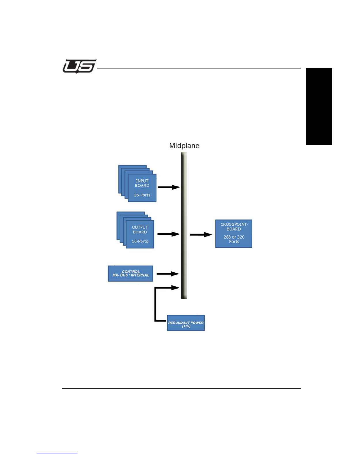
The UDS system is based upon a four board architecture similar to other Utah Scientific
routing switchers. These four boards are made up of an Input board, a crosspoint board,
midplane, and output board.
Input or Output boards can be removed or added (via the midplane) in the field to expand
systems, change IO types or replace defective modules.
Section 1
Figure 1-1.
The UDS system is designed to carry SDI signals. The system natively supports and
reclocks SMPTE259C, SMPTE292, SMPTE424, ST2081, ST2082, and DVB-ASI signals
with a maximum data rate of 11.88 Gb/Sec.
Section 1 1-3
Page 20

System Setup
The reclocking mechanism within the UDS automatically bypasses when a signal that is
not one of these standards is presented to it, allowing non-reclocked routing of any signal
from 18 Mb/Sec to 11.88 Gb/Sec.
The coaxial version of IO cards uses the HD-BNC connector offered by Amphenol and
Samtec. It provides superior performance and density while allowing connection of
industry standard Belden 1694 cable or other cable types with standard tools. Visit
http://hdbnc.amphenolrf.com/ for more information.
UDS Routing Switchers are powered by 12V DC connections. Systems are delivered with
1 power supply as a standard. (The part number for the optional redundant power supply
is USI 94001-9006.)
3G/12G
The UDS 288 supports two types of IO cards; those that support signals p to 3Gb/Sec and
others that support up to 11.88 Gb/Sec signals.
1-4 System Setup
Page 21
Router Hardware Description
Analog Audio R
Digital Video
Digital Audio 1/2
Digital Audio 3/4
Digital Audio 5/6
Digital Audio 7/8
Analog Video
Analog Audio L
One
Signal
Level
Signal Levels
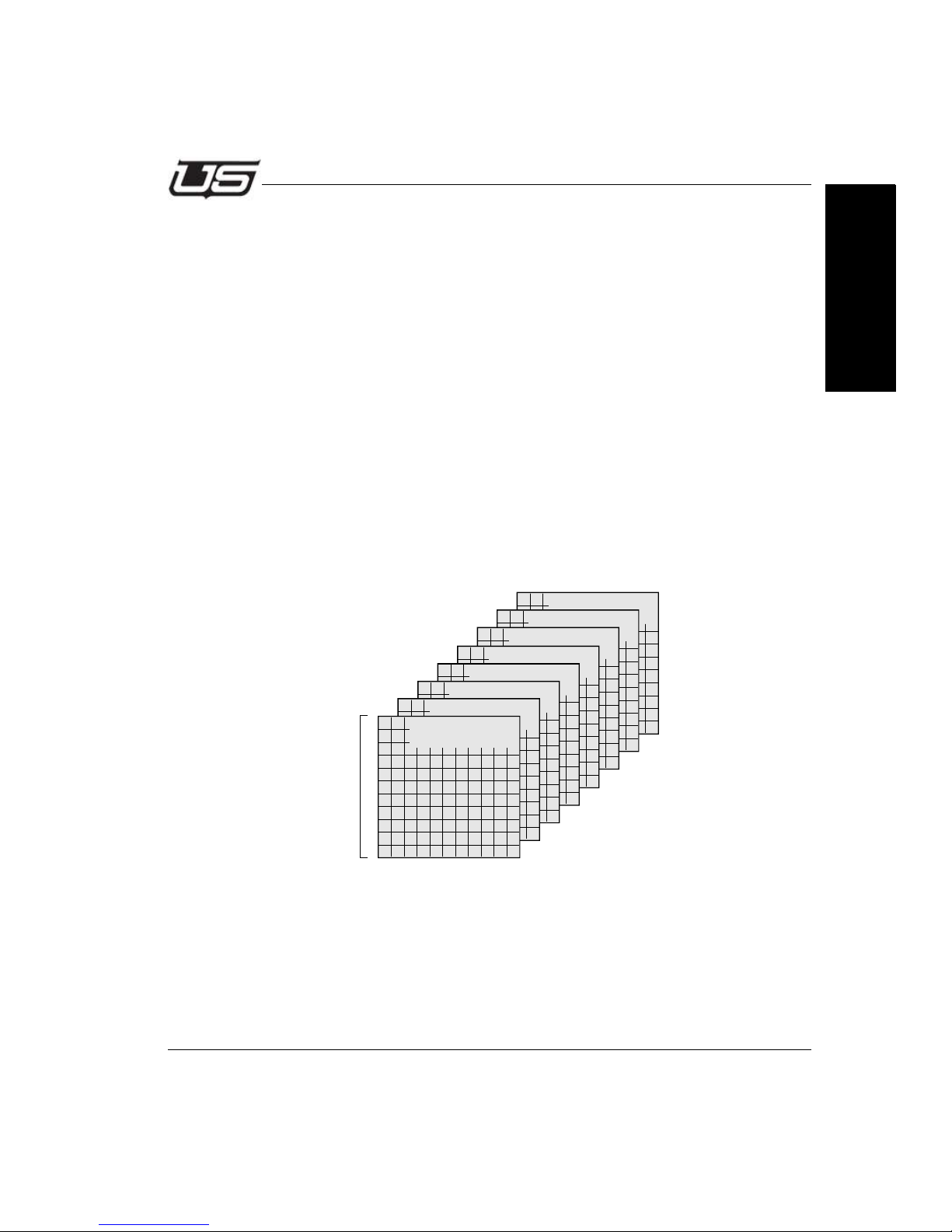
A "signal level" represents one of many specific types of audio or video elements that a
routing switcher is capable of handling. The typical signals capable of being switched are:
• Analog Video
• Analog Audio (stereo with left and right channels).
• Digital Video
• Digital Audio (dual channel – stereo pair)
• High Definition Video.
Some systems may be configured with one signal level, while others may be configured
with multiple signal levels.
While the diagram in the previous section shows only one signal level, a multi-signal level
system is capable of routing any combination up to 32 levels – each with its own matrix
and cross-points.
The figure below illustrates eight signal levels in a 10 X 10 matrix system.
Section 1
Signal routers are typically much larger than a 10 X 10 matrix, depending on user needs.
Each signal level may also have different sizes of matrices and do not all need to be the
same size.
Section 1 1-5
Page 22
System Setup
Hardware Installation
Initial Inspections
Check the contents of the shipment for completeness and possible transport
damage.
If the contents are incomplete or damaged, contact Utah Scientific Inc
immediately for repairing or replacement parts of the equipment.
Before Applying Power
Verify that the product is configured to match the available main
power source per the input power configuration instructions
provided in this manual.
The modules of the UTAH-100/UDS frame may only be installed in
specific positions. Interchanging power and function modules may
harm the UTAH-100/UDS frame permanently.
Service
Servicing, adjustments, maintenance or repair of this product may be performed
by qualified personnel only. Adjustments described in this manual may be
performed with power supplied to the product while protective covers are
removed. Energy available at many points may, if contacted, result in personal
injury. Capacitors inside this product may still be charged even when
disconnected from their power source.
1-6 System Setup
Page 23

Hardware Installation
Initial Setup
1. Remove the chassis and inspect the unit carefully for damages that may
have occurred during transport.
2. Check that the frame is installed so the airflow though the unit is
unrestricted. No forced ventilation is required under normal operating
conditions.
3. Connect the external power cord to the corresponding power connector
on the rear side of the UTAH-100/UDS frame. Check that the Power LED
on the front panel is lit. Green LEDs indicate normal operation, while Red
LEDs indicate a failure condition. If a failure occurs; potentially related to
no power, inoperative fan, or temperature range, please disconnect
power and contact UTSCI support for assistance.
Section 1
Section 1 1-7
Page 24
System Setup
Primary Crosspoint
Primary Power Supply
Redundant Power Supply
Redundant Crosspoint
Input Cards
Output Cards
015 - 000
383 - 368
000 - 015
368 - 383
Installation
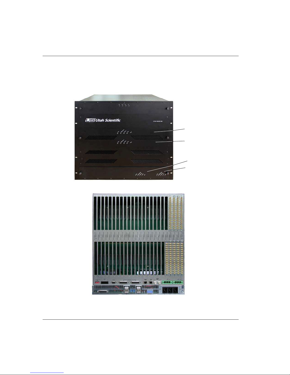
288x288 UDS System
Figure 1-2. UTAH-100/UDS 288 - Front
Figure 1-3. UTAH-100/UDS 288 - Rear
1-8 System Setup
Page 25

Contents
Installation
• 1 Primary Crosspoint card
• 1 Redundant Crosspoint card
• 18 Input card Slots.
• 18 Output card Slots.
• 1 Primary Control Card Slot
• 1 Redundant Control card slot
• 1 12V Power Supply with chassis
• 1 Redundant 12V Power Supply slot
• 4 internal cooling fans located near the chassis top. Air is drawn
from the front and exhausted through the sides.
This system is only capable of being controlled via MX Bus, as the internal controller
option is not available for this frame. When encoding an SC-4, 400 or 40 to utilize this
frame, you must first set the MX-BUS level of the router as described in the MX-Bus
Based Systems section of this manual.
Section 1
Section 1 1-9
Page 26
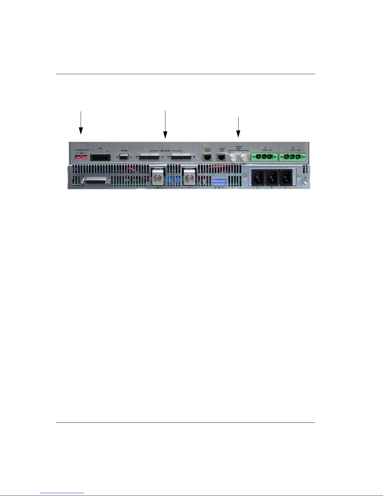
System Setup
MX Bus
Dip Switches
Video Ref
Rear Panel Considerations
Figure 1-4.
MX Bus
This is the control bus between the UDS 288 and the SC-4 controller. Each chassis contains
two connectors, fed through either side, then distributed to the next piece of equipment from
either side.
Dip Switches
The dip switches are used to set the location of the router within the MX-Bus system. Usage
example: A first level, binary setting would require all switches to be placed in the down
position.
Video Ref
Used as a switching reference. Provides analog blackburst or tri-level sync. This port is a
loop thru, and the unused BNC must be terminated in 75 Ohms.
1-10 System Setup
Page 27
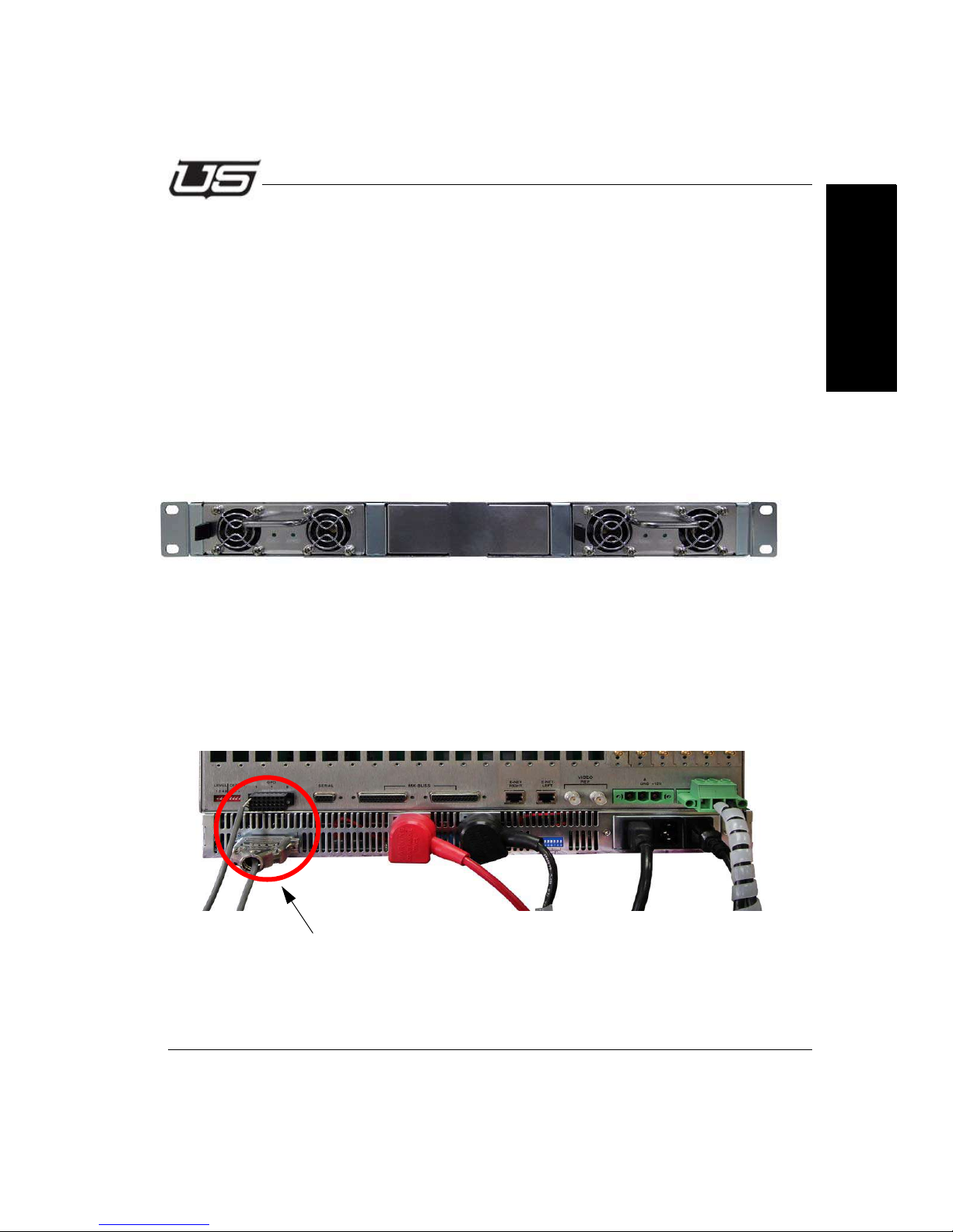
Installation
Alarm Cable (part #121409-1)
This connection is required for system operation
Power Supplies
Connecting and Disconnecting Power
The power system within the UDS 288x288 router consists of a 1 RU power supply shelf
that has up to (2) 12 VDC power supplies. Within this architecture, there is no power supply
assembly internal to the chassis itself, as each module receives and converts the 12V bus to
its own internal requirements. Overall power consumption depends upon loading, but an
average fully loaded system consumes 350 watts.
The standard power supply assembly shipped with a router (that is to be powered via AC
mains) contains two rectifier modules. The power supply shelf contains 3 slots, however
only one is required for system operation. A second power supply can be added for
redundancy, and will load share when a redundant power supply is in the system.
Figure 1-5. Power Supply (front view)
From the power supply assembly, two 8 AWG wires carry power as follows;
Section 1
• (1) black wire connect to negative (-) terminal of the power supply
• (1) red wire connects to the positive(+) terminal of the power supply,
and
passes through a 40A fuse prior to connecting to the +12V input of the
router. This fuse is a Littlefuse part number 142.6885.5402, or USI part
number 41913-0001.
Figure 1-6. Power supply - connected
Section 1 1-11
Page 28

System Setup
Determining and Setting Router Signal Levels
Signal levels are preset at the factory and tested during manufacturing, determined by
customer input and requirements. The installation of your new Utah-400 Router
should not require any signal level changes to operate after the new installation.
By definition, a signal level represents distinct elements of the broadcast system.
These individual elements include, but are not limited to, High Definition Video, SDI
Video, Digital Audio, Analog Video, Analog Audio and Data Routers. For additional
information relating to signal levels, refer to “Signal Levels,” on page 1-5.
1-12 System Setup
Page 29
Installation
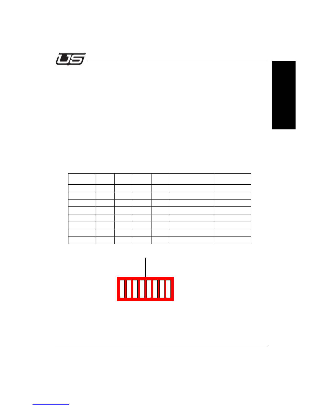
LEVEL OFFSET
1 2 4 8 I O
Switch Settings
Should you ever need to change the signal level of your router it is useful to determine:
• What new signal level is required.
• If other signal levels will have to be modified to accommodate the new signal level.
• Additional encoding requirements necessitated by the change.
1. Locate the dip switch on the control I/O panel at the rear of the chassis.
2. The four level bits work in a binary addition mode. Possible values range from
0 (all down) to 15 (all up). 0 is level 1 in an SC-4 control system, and 15 is level
16.
3. Set the switches to the level you have chosen according to the following table.
Switch1248Binary ValueSC-4 Level
OFF OFF OFF OFF 0 1
ON OFF OFF OFF 1 2
OFF ON OFF OFF 2 3
ON ON OFF OFF 3 4
OFF OFF ON OFF 4 5
ON OFF ON OFF 5 6
... ... ... ... ... ...
ON ON ON ON 15 16
Section 1
Figure 1-7.
Unlabeled Dipswitch Positions
The last two dipswitch locations must be down in all cases.
Section 1 1-13
Page 30
System Setup
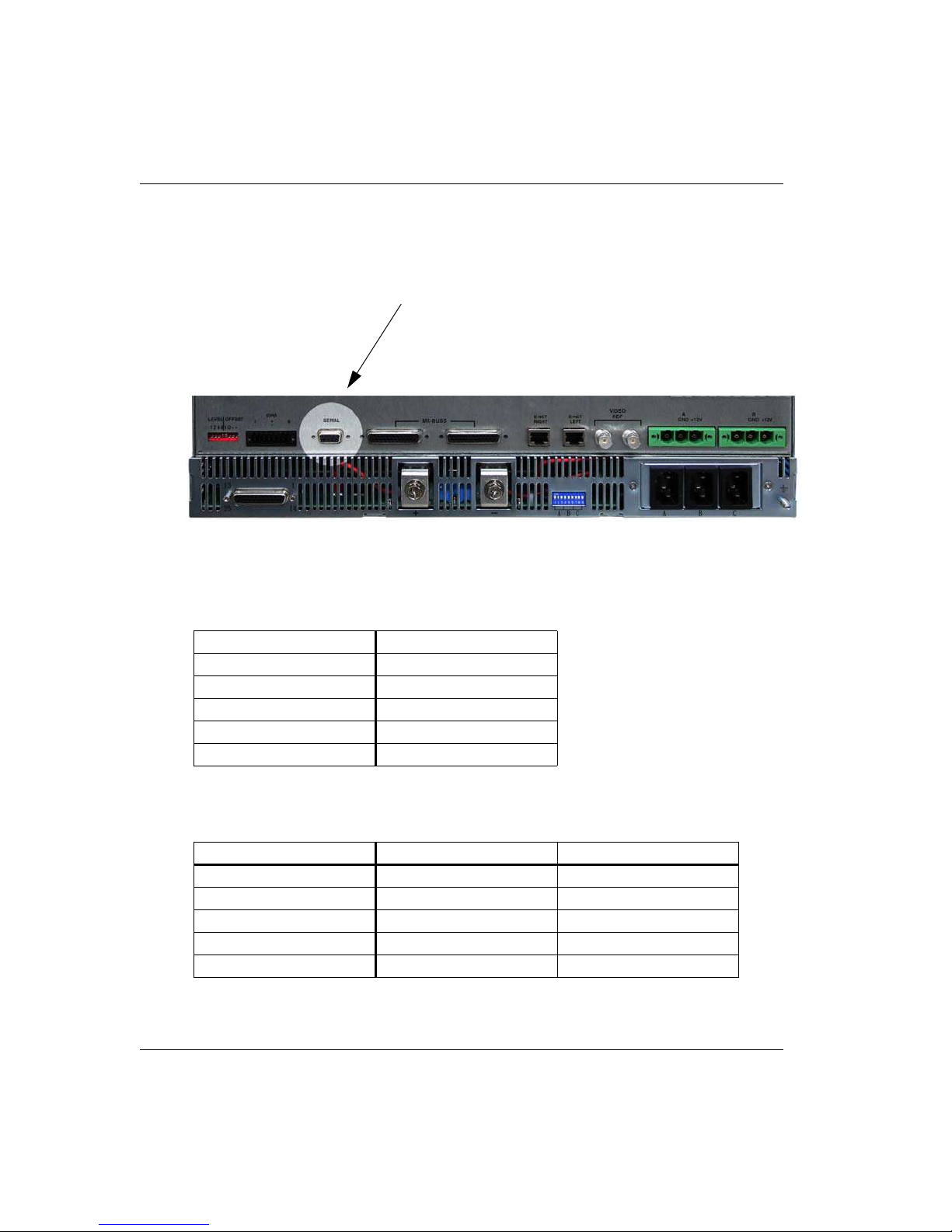
Serial Port
This is a RS-232 DTE port, and is used as for diagnostic purposes. A terminal emulation
program such as Tera Term is used for communication.
Figure 1-8.
Baud Rate Information
Baud 115,200
Data Bits 8
Stop Bits 1
Parity Bits N
Handshake XON/XOFF
Output Translation CR = CR
Pinout Information
Pin Signal Name Direction
2 Receive Data In
3 Transmit Data Out
7RTSOut
8CTSIn
5 Ground
1-14 System Setup
Page 31
Installation
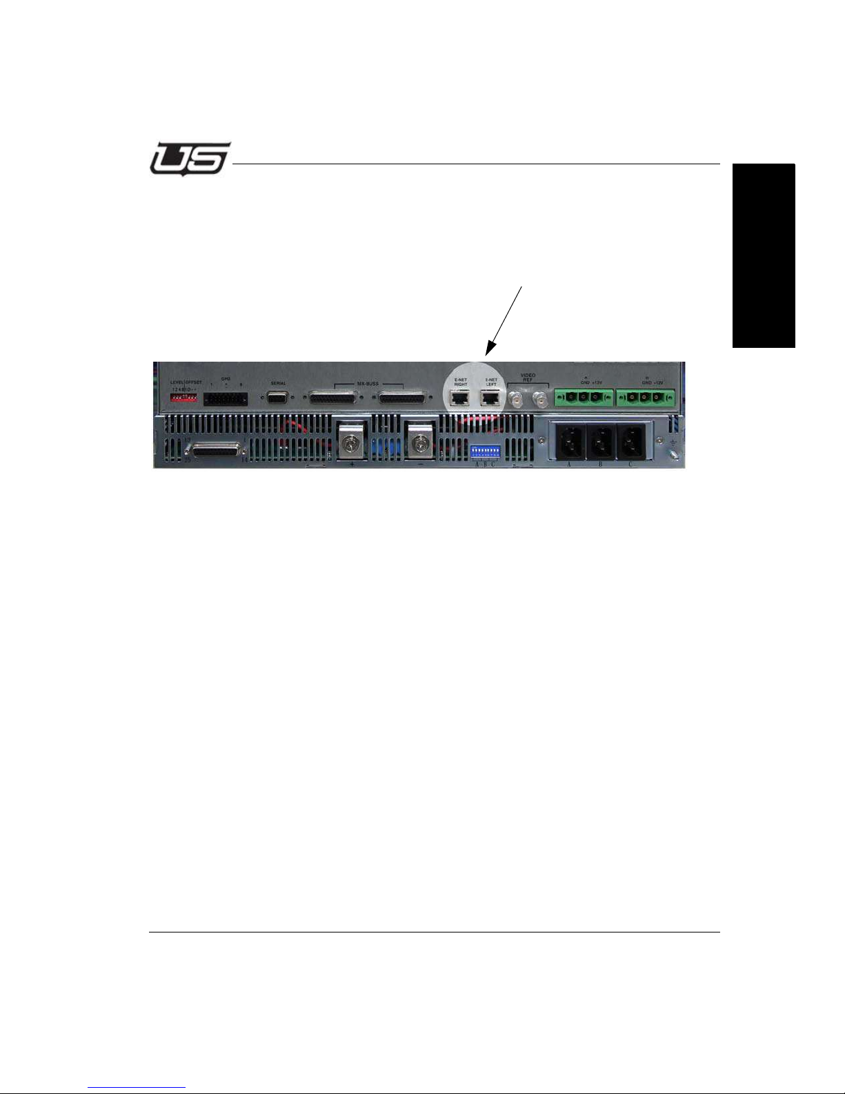
Ethernet Port (Future Use)
The 10/100 ethernet ports are used as a diagnostic and monitoring ports. Connect these
to a standard ethernet network. Each port is directly connected to its corresponding controller located in the chassis.
Figure 1-9.
Section 1
Section 1 1-15
Page 32
System Setup
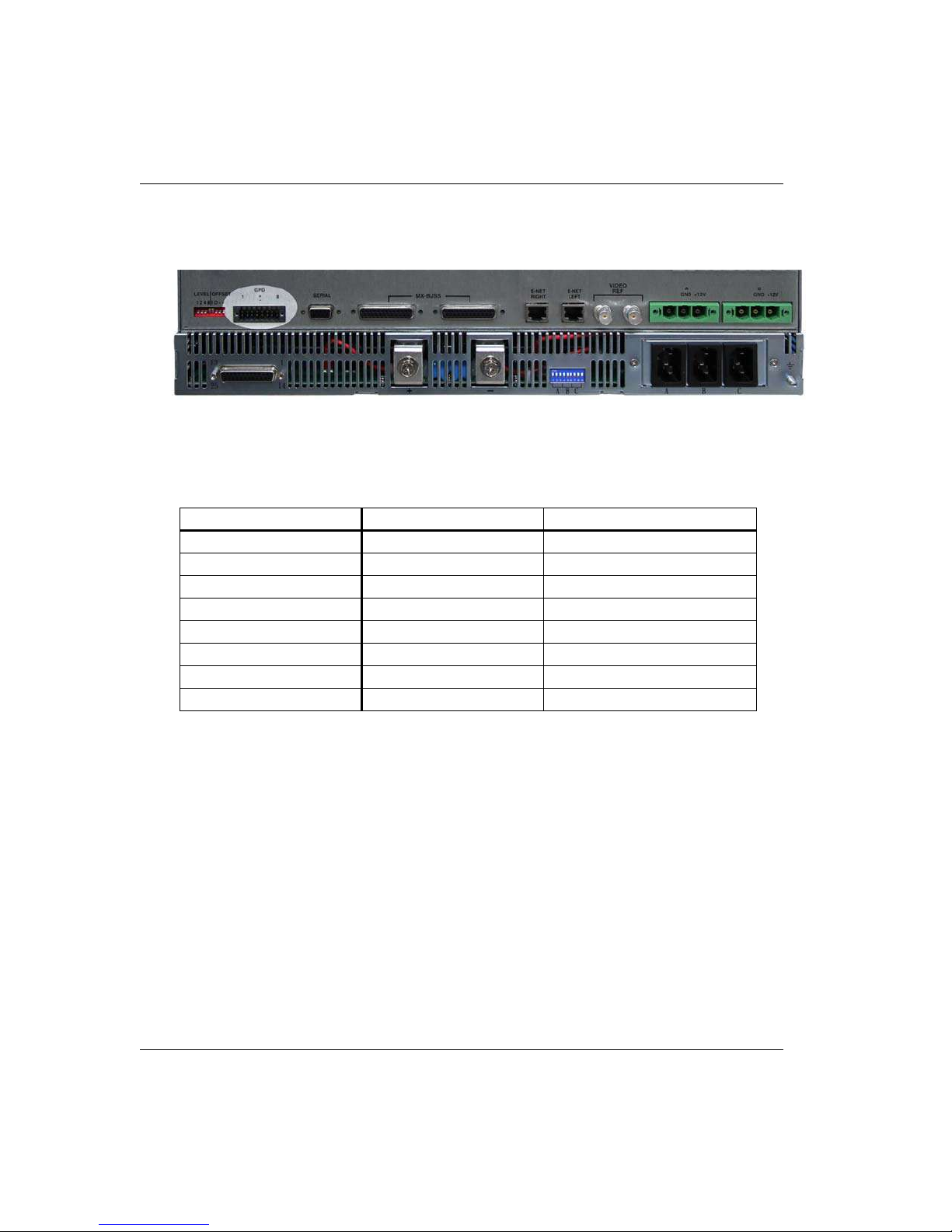
GPIO Port
Figure 1-10.
The GPIO block provides the following functions:
GPIO# Direction Function
1 INPUT Indicate Power Supply Failure
2 INPUT Unconnected (TBD)
3 INPUT Controller Changeover
4 INPUT Crosspoint Changeover
5 OUT SMPTE Alarm
6OUTTBD
7OUTTBD
8OUTTBD
To activate a GPI input, short the + and - leads together.
When the SMPTE Alarm is active, there will be a short circuit across the + and - pins.
1-16 System Setup
Page 33
Installation
Connecting Cables
Video Cables
Use high quality coaxial cable with HDBNC ends to connect to the UDS system. The input
and output numbers are silk-screened on the rear of the chassis.
IMPORTANT NOTE:SC4 and SC400 control systems are zero based. This
means that SC4 input 0 corresponds to the input labeled 1 on the
router, 1 corresponds to 2, etc. Make sure to take that into account
when connecting cables.
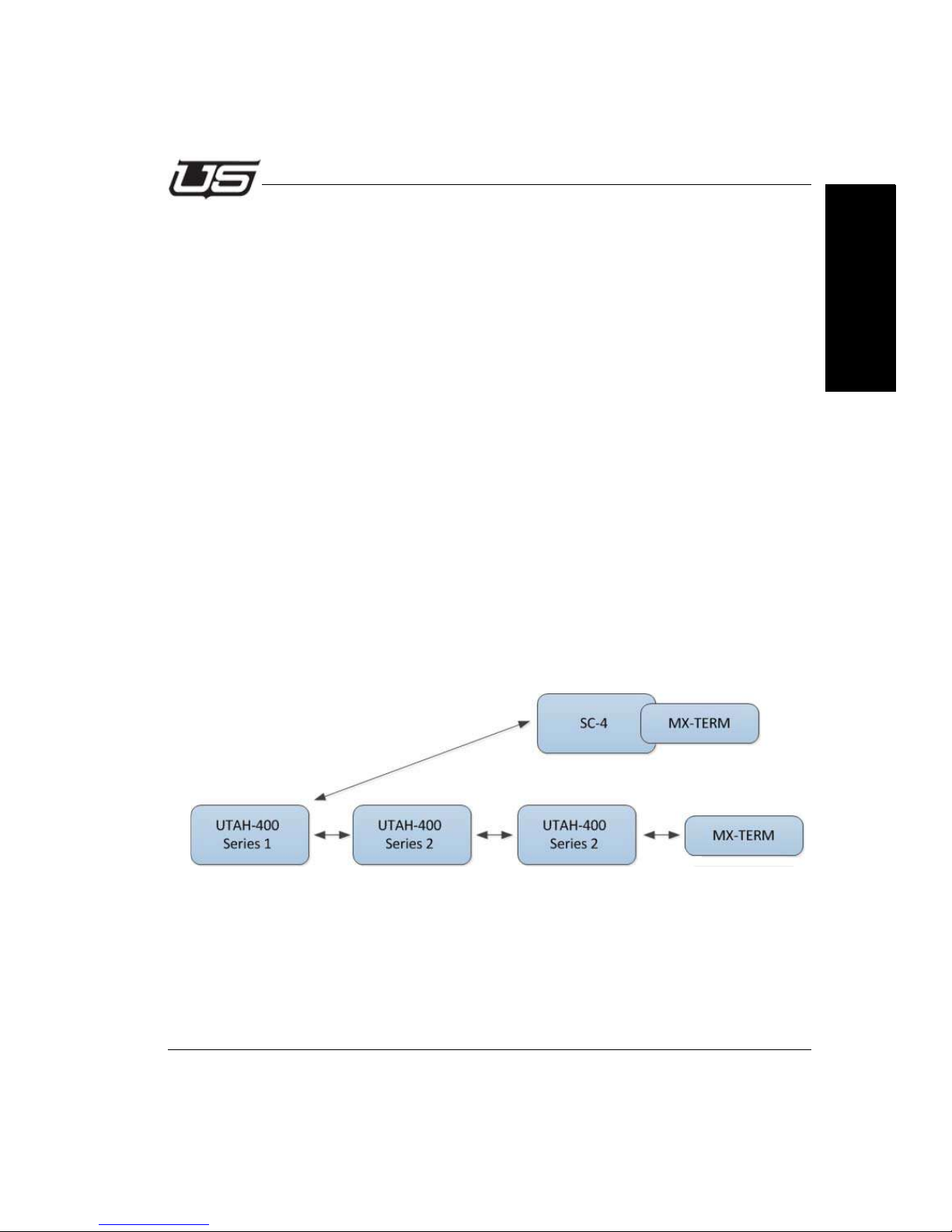
MX Bus Cables
The UDS 288 routing system utilizes the MX-Bus control system. It must be connected to
the SC-4 control system to switch its inputs and outputs. In addition, the proper levels and
offsets must be set on the UDS 288 routing system(s) so they will operate on the proper
signal levels.
The MX-Bus is a daisy chain configuration, must not exceed 300 feet (91.4 meters) in
length; and must be terminated at both ends of the daisy chain.
Your UDS 288 router is shipped standard with one MX-Bus Cable - 10 ft. (USI Part Number:
80299-10). Other lengths are available and may be ordered through Utah Scientific sales at
1 (800) 453-8782.
Section 1
Figure 1-11.
Note the necessary termination on the MX-Bus in the above illustration.
Section 1 1-17
Page 34
System Setup
UDS288 Crosspoint Card – 121414-1
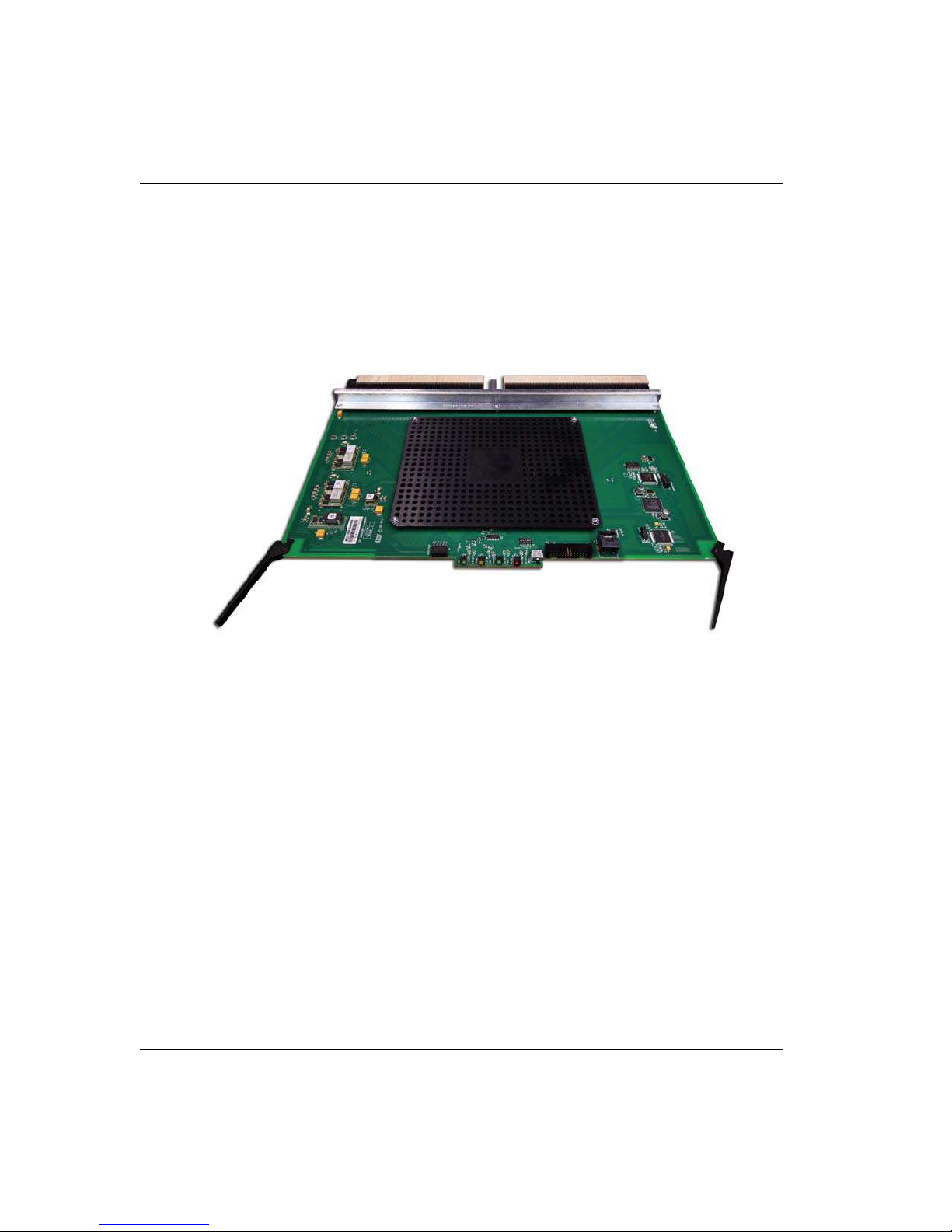
General
The 121414-1 Crosspoint Card is the central component in the 10 RU UDS288 router. It contains circuitry to control a 288x288 switching array based on commands from the MX-BUS,
power supply circuitry and alarm reporting circuitry.
Figure 1-12. Crosspoint Card - part # 121414-1
Circuit Description
The upper end of the card is the power supply section. There are modules that convert the
system 12V down to the 3.3V, 2.5V, 1.8V and 1.2V. U7 monitors these voltages and will
generate alarms if any are faulty. PWR OK, a green LED on the board front edge, lights
when all supplies are good.
The lower end of the card contains all of the control circuitry on the board. This consists
mainly an 16 bit DSP, and a FPGA. The FPGA receives commands from the external
MXBUS and switches the crosspoint chip appropriately, while the DSP monitors the health
of the board and reports that back to the system level Frame Controller Module for reporting
to the external world.
The video switching core of the system is in the center of the board, under the heat sink.
This is a 3.2Gb/Sec 288x288 crosspoint chip in a 2398 ball BGA package. It receives the
1.2V and 1.8V rails from the power supply section, a 30 bit control bus from the FPGA, and
288 inputs from video input cards and drive 288 video outputs to output cards.
1-18 System Setup
Page 35
Installation
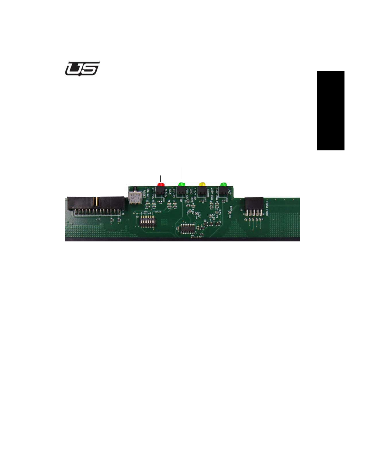
DS5 - Health Indication - Red/Problem
DS1 - (Power OK) Green
DS6 – (ACT) Green – On if OK
DS7 - (COMM) Yellow
Controls and Indicators
Controls
SW2 – Momentary push button reset switch. Resets all processing on the card.
SW1 – 8 Position Dipswitch. Used for board programming and custom settings.
J8 - Header for connection of a JTAG pod for programming the FPGA.
J14 – Header for programming the DSP, from a PC parallel port.
P1 – Used for serial diagnostics of the card from a RS-232 port.
Section 1
Indicators
DS4 – 1.2 or 1.8V failure indication – RED.
DS3 – 2.5V failure indication – RED.
DS2 – 3.3V failure indication – RED.
DS8 – XP Power Supply OK indication – GREEN.
DS5 – Health Indication – (ALARM)RED – On if there is a problem.
DS7 – Communication from FCM indicator – (COMM)Yellow.
DS6 - Communication to crosspoint chip – (ACT)GREEN – On if OK.
DS1 – Power Supply OK LED – (PWR OK)GREEN.
DS9 – Seating LED – Indicates that the crosspoint card is correctly installed in its slot
when green.
DS10 – FPGA programming complete – GREEN.
DS11 – Scangate active LED – Yellow.
Section 1 1-19
Page 36
System Setup
UDS288 Frame Controller
Overview
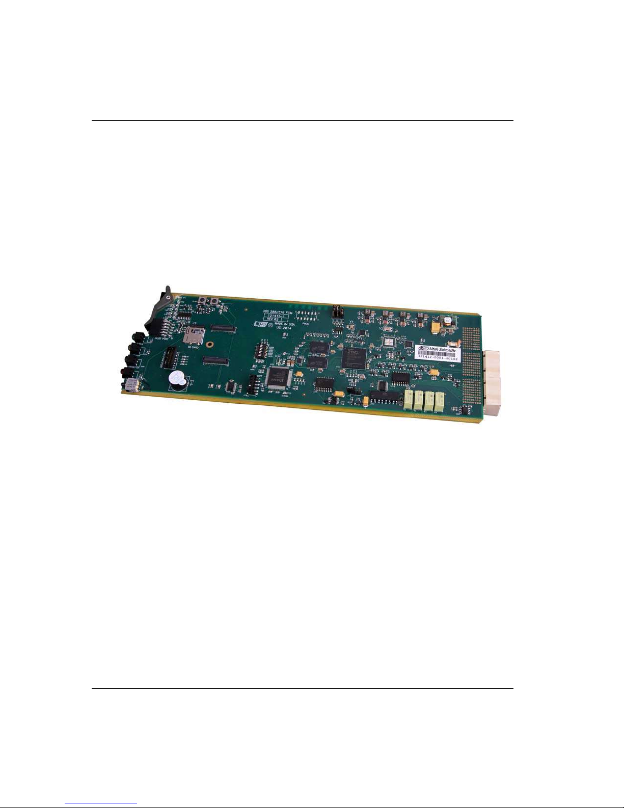
Part # 121412-1, the UDS288 Frame Controller Module (FCM) has the system function of
coordinating all switching and reporting functions from the control system and applying
them to the router hardware. It has several communications busses, including the Utah
Scientific MX-Bus which carries crosspoint switches and general status to and from the
control system, a diagnostic serial port, and an Ethernet port for more detailed status and
control.
Figure 1-13. UDS-288 Frame Controller - 121412-1
Circuit Description
The heart of the FCM is a Kinetis K70 SOM/FPGA combination that allows the FCM to
process the large amount of switches required for this system.
Dedicated high speed control and status busses to each crosspoint and 6 busses that
communicate to the total IO cards make up the interconnect between the FCM and the
other boards in the system. The FCM operates as a redundant pair with an identical card
in the adjacent slot.
1-20 System Setup
Page 37
Installation
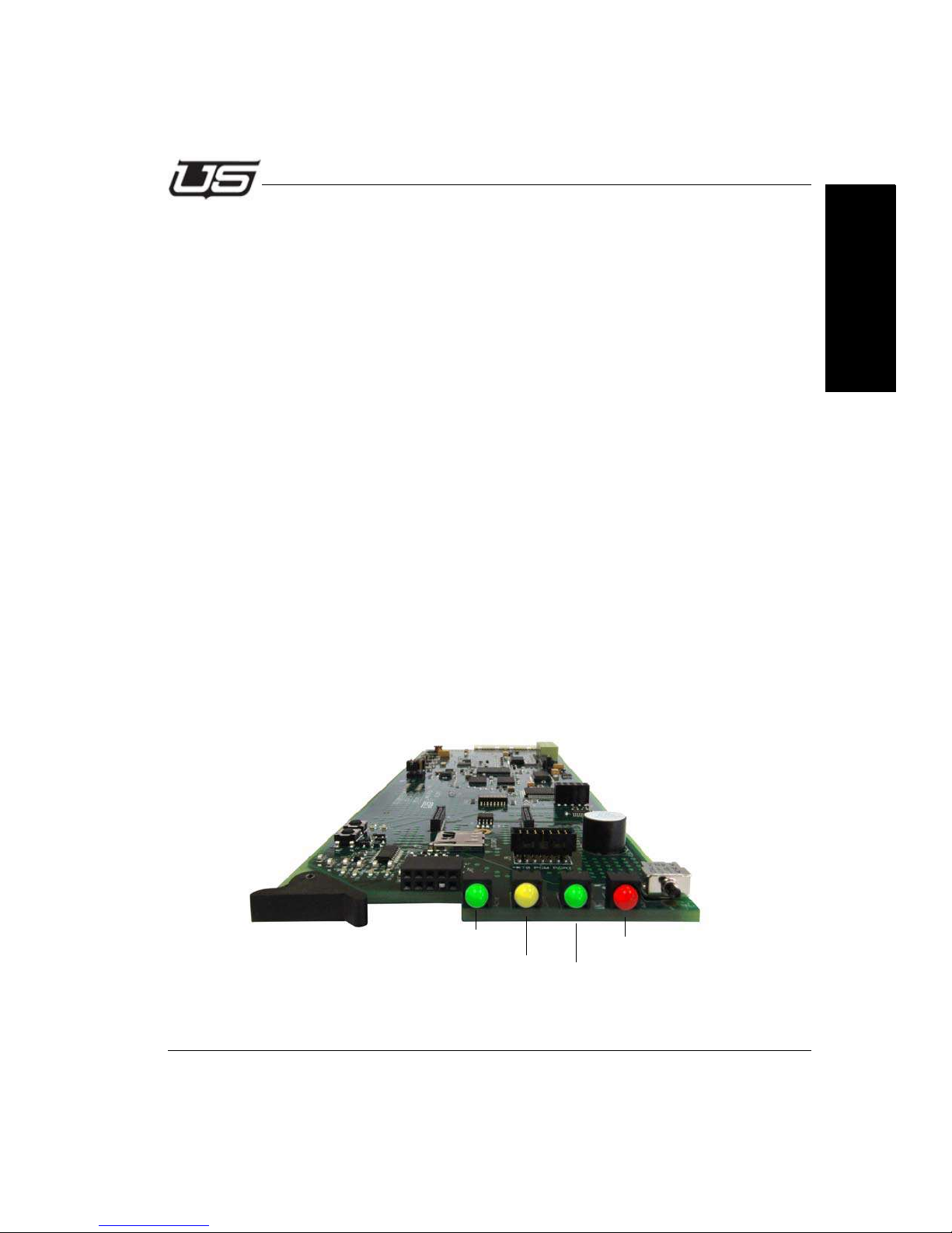
DS5 – Active – Green
DS6 – Comm – Yellow
DS8 - Power OK - Green
DS11 - SMPTE Alarm - Red
UDS288 Frame Controller
Controls and Indicators
Controls for this card are concentrated on the router rear panel, in the Ethernet and
Diagnostic serial ports. The only board level control is the Speaker Enable or Disable
jumper, J11, that allows the audible alarm to be turned off (on = pins 1-2, off = 2-3). The
audible alarm sounds any time that the SMPTE alarm is on.
The following LED’s indicate different board conditions:
• DS11 – SMPTE Alarm – (Alarm)RED – Red when any error
condition exists.
• DS5 – Active – (Active)Green – When illuminated indicates that
this is the Active card in the pair and is currently managing the
system.
• DS8 – Power OK – (PWR OK)Green – Illuminated when all on
board power supplies are OK.
• DS1 – 1.0 & 1.5V LOW - RED - Indicates an alarm condition for the
on board 1.0V and 1.5V power supply.
• DS2 – 1.8V LOW - RED - Indicates an alarm condition for the on
board 1.8V power supply.
Section 1
• DS3 – 3.3V LOW - RED - Indicates an alarm condition for the on
board 3.3V power supply.
• DS4 – 5V LOW - RED - Indicates an alarm condition for the on
board 5V power supply.
Section 1 1-21
Page 38
System Setup
UDS288 FCM Field Software Update
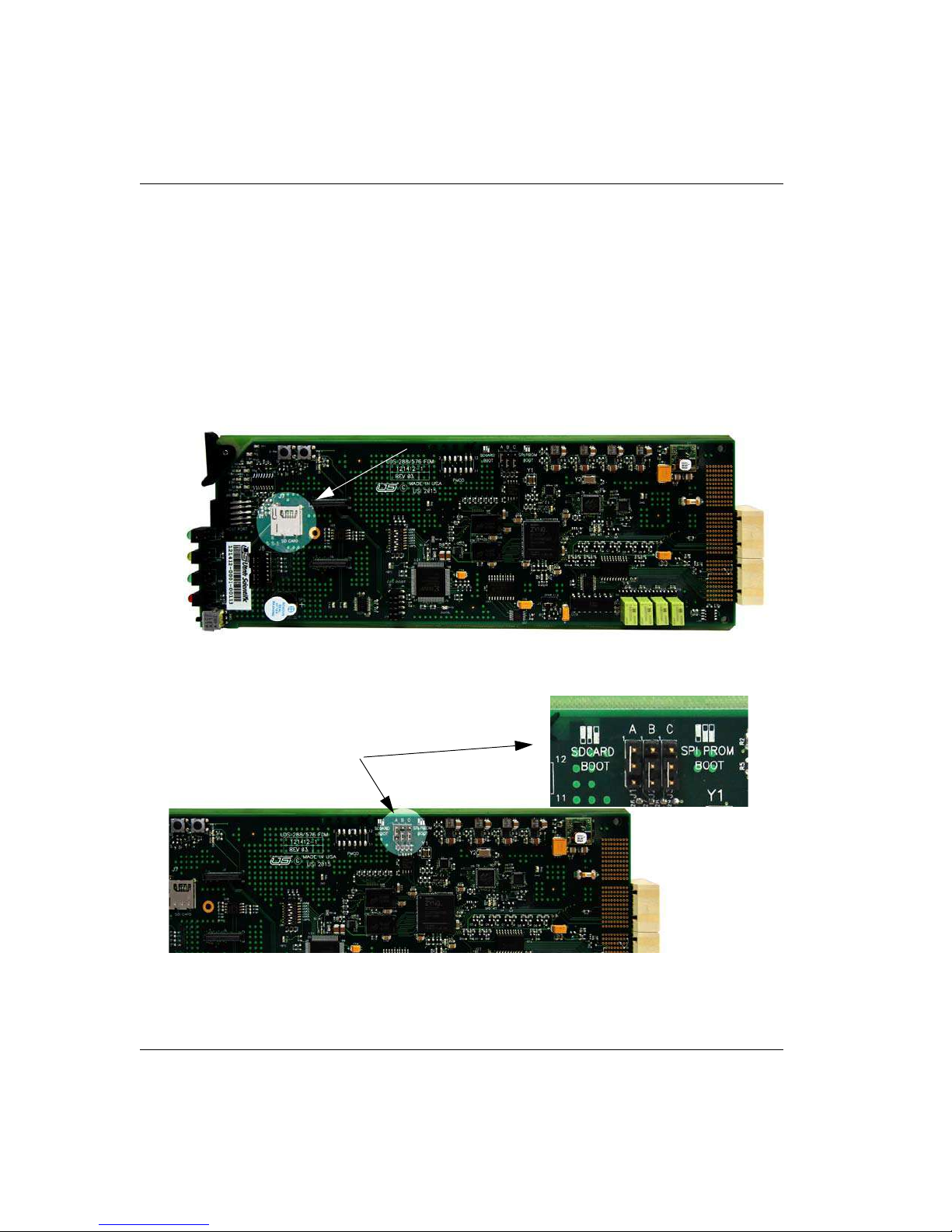
The UDS 288 FCM, part number 121412-1, has the ability to boot from an SD Card as a
software update mechanism.
All cards ship from the factory using internal memory to load their programming files from.
If a software update is required, you will be shipped an SD Card preloaded with the
correct software from USI service personnel. The update is a two step process.
1. Insert the SD card into the holder pictured below.
Figure 1-14.
2. Move the jumpers J1, J23 and J3 into the ‘SDCARD Boot’ position.
Figure 1-15.
3. Re-install the card and continue with normal operation.
1-22 System Setup
Page 39
Installation
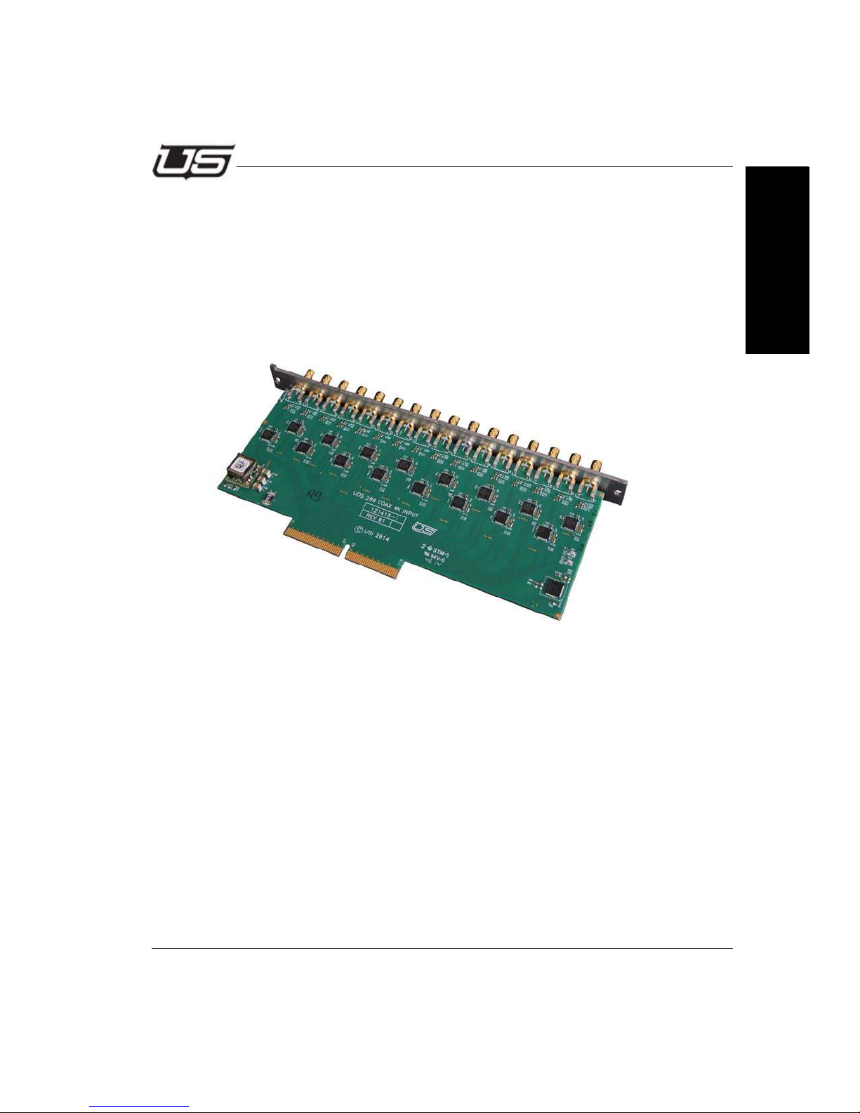
Coax Input Card 121415-1 (up to 12G)
General
The SDI Coax input card is responsible for receiving, reclocking, and presenting the input
signals to the crosspoint card. It has 16 HDBNC connectors, 16 SDI Cable equalizers,
with reclockers. The reclocking components automatically detect, lock to and re-time the
incoming SDI signals. If a non-standard signal is presented to the card, the reclocker will
automatically bypass and allow the signal thru without re-timing it.
Section 1
Figure 1-16.
Circuit Description
12 V is received by this card and regulated down to 2.5V.
SDI cable equalizers are capable of equalizing more than 50 meters of 1694A cable when
using 11.88 Gbps signals.
There is an I2C based IO expander that identifies the card to the control system. This
component also allows the system to provide status of IO card functionality to the user
interface.
Controls and Indicators
This card has a single Power OK indicator, DS1, which shines thru the rear of the chassis
to indicate the card is active.
Section 1 1-23
Page 40
System Setup
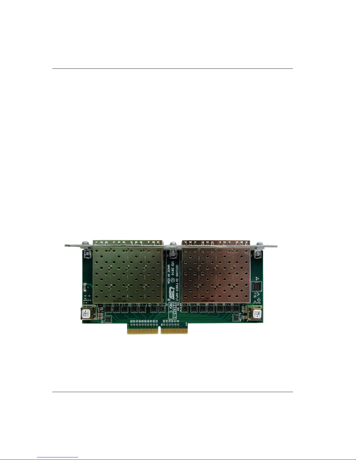
Fiber Input Card 121423-1 (up to 3G)
General
This card can be populated with a variety of SFP receiver devices to allow for different
functionality. It allows for 8 dual DFP connections, allowing 16 total inputs. The list of SFP
module types is –
1. DUAL Single mode 1220-1620nM SFP – 94061-01.
2. DUAL CVBS to SDI Converter (HDBNC) – 94061-06.
3. DUAL SDI Receiver with reclocking – 94061-09.
4. DUAL Multi Mode 850nM SFP – 94061-11.
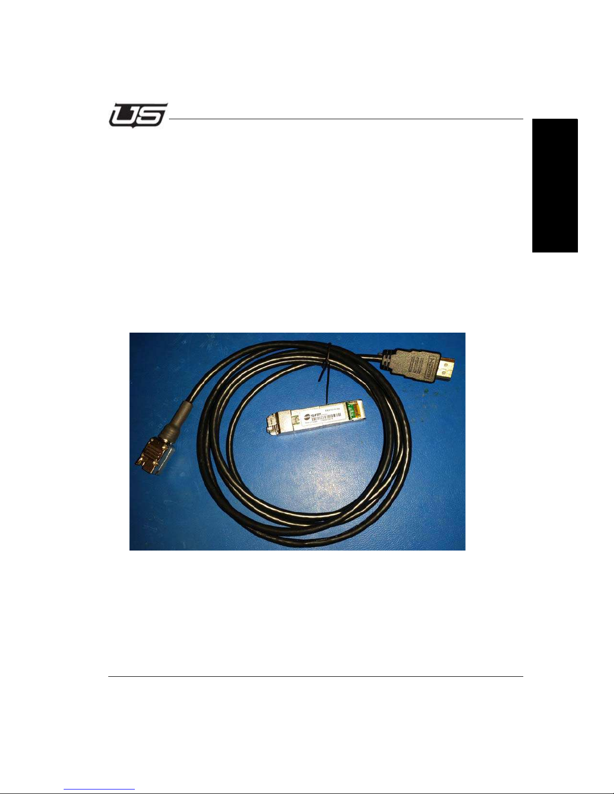
5. HDMI Receiver with HDMI connectors. 14003-40
6. HDMI Receiver with DVI connector. 140033-41
The HDMI Receiver occupies both ports in the SFP cage, making 1 input inaccessible. The
receiver uses the upper input. (i.e., if the slot corresponds to inputs 1 and 2, the signal will
display on the router input 2).
Figure 1-17.
1-24 System Setup
Page 41
Installation
Circuit Description
Component U2 receives and regulates 12V into 3.3V to be used by the SFP’s and 2x2
crosspoint 2G.
Component U19 receives and regulates 12V into 1.2V to be used by the 2x2 crosspoint
2G.
Component U1 is the system identifier I2C based IO expander, which allows board
presence to be communicated to the user.
Controls and Indicators
None.
Control Interface
Section 1
Figure 1-18. HDMI SFP
Section 1 1-25
Page 42
System Setup
Fiber Output Card 121424-1 (up to 3G)
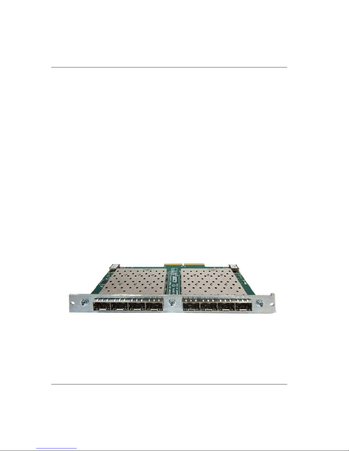
General
This card can be populated with a variety of SFP transmitter devices to allow for different
functionality. It allows for different functionality. It allows for 8 dual DFP connections,
allowing 16 total outputs. The list of SFP module types is -
• DUAL Single mode 1310nM SFP - 94061-02
• DUAL SDI to CVBS Converter (HDBNC) - 94061-03
• DUAL SDI Transmitter reclocking - 94061-06
• DUAL Multi Mode 850nM SFP - 94061-12
• CWDM Modules of different frequencies are also available.
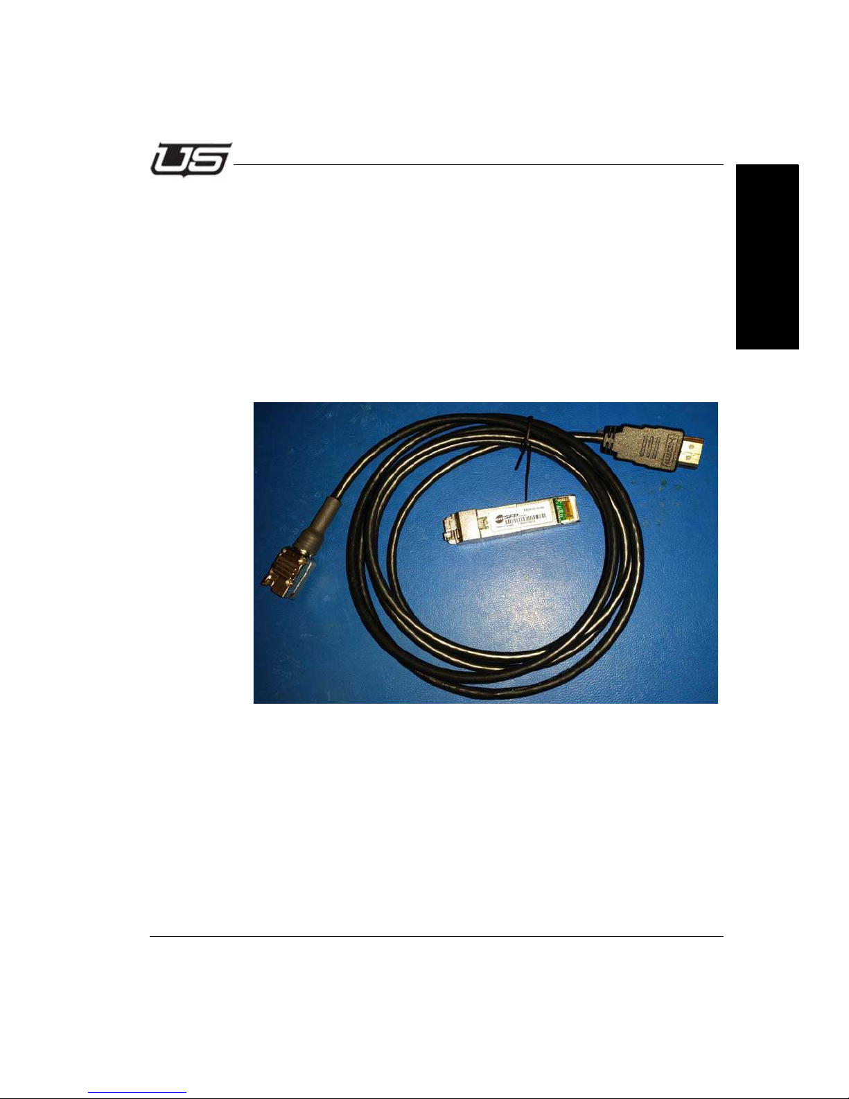
• HDMI Transmitter with HDMI connector - 140033-42
• HDMI Transmitter with DVI connector - 140033-43
Note: The HDMI transmitter occupies both slots in the SFP cage, making 1
output inaccessible. The transmitter uses the lower port. (i.e., if the
slot corresponds to router outputs 1 - 2, the SFP will output the
signal switched to output 1.
Figure 1-19.
1-26 System Setup
Page 43
Installation
Circuit Description
Component U2 receives and regulates 12V into 3.3V to be used by the SFP’s.
Component U19 is the system identifier I2C based 1.2V expander, which
allows board presence to be connumicated to the user.
Controls and Indicators
None.
Control Interface
Section 1
Section 1 1-27
Figure 1-20. HDMI SFP
Page 44
System Setup
Coax Output Card 121417-1 (up to 3G)
General
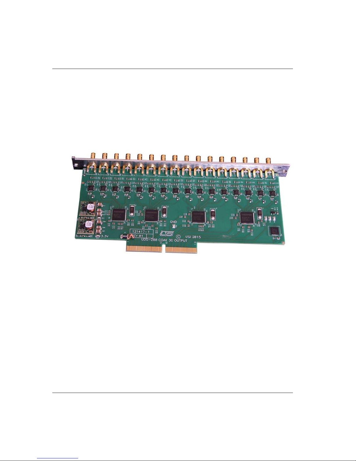
The SDI Coax Output card is responsible for driving the switched video signals down
coaxial cables in a SMPTE compliant fashion. It has 16 HDBNC connectors and 16 SDI
Cable drivers on it.
Figure 1-21.
Circuit Description
12 V is received by this card and regulated down 3.3V and 1.2V.
There are four Quad Reclockers that supply high quality signals to the cable drivers for a
nominal output of 800 MV. There is a I2C based IO expander that identifies the card to the
control system. Controls and Indicators.
This card has a single Power OK indicator, DS1, which shines thru the rear of the chassis
to indicate the card has power (3.3V).
1-28 System Setup
Page 45
Installation
Coax Output Card 121416-1 (up to 12G)
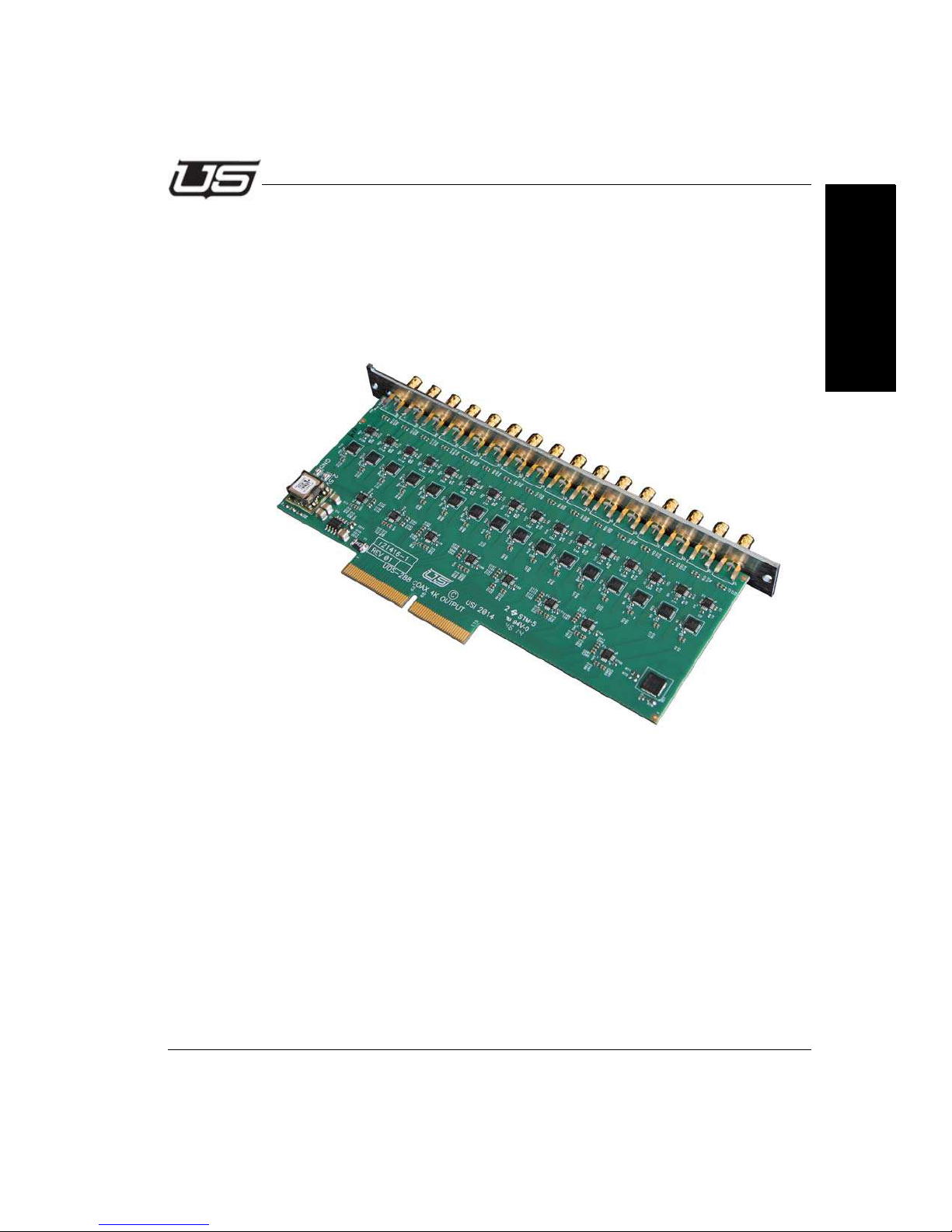
General
The SDI Coax Output card is responsible for driving the switched video signals down
coaxial cables in a SMPTE compliant fashion. It has 16 HDBNC connectors and 16
SDI Cable drivers on it.
Section 1
Figure 1-22.
Circuit Description
12 V is received by this card and regulated down 3.3V and 2.5V. There are eight high
bandwidth switches that route signals from the active crosspoint card to reclockers
and cable drivers for a nominal output of 800 MV. There is an I2C based IO expander
that identifies the card to the control system. Controls and Indicators.
This card has a single Power OK indicator, DS1, which shines thru the rear of the
chassis to indicate the card has power (3.3V).
Section 1 1-29
Page 46
System Setup
Coax Output Card 121417-1 (up to 3G)
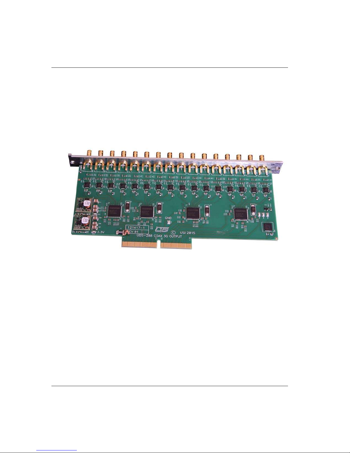
General
The SDI Coax Output card is responsible for driving the switched video signals down
coaxial cables in a SMPTE compliant fashion. It has 16 HDBNC connectors and 16 SDI
Cable drivers on it.
Figure 1-23.
Circuit Description
12 V is received by this card and regulated down 3.3V and 1.2V.
There are four Quad Reclockers that supply high quality signals to the cable drivers for a
nominal output of 800 MV. There is a I2C based IO expander that identifies the card to the
control system. Controls and Indicators.
This card has a single Power OK indicator, DS1, which shines thru the rear of the chassis
to indicate the card has power (3.3V).
1-30 System Setup
Page 47

Introduction
Section 2
Section 2
UTAH-100/UDS Browser Utility
Network Configuration
Introduction
This guide describes the network configuration for the UTAH-100/UDS Router and Panel.
Using two setup scenarios; New Configuration on an Independent Network, and New
Configuration on an Existing Network. These are the first steps required to configure and
control the system.
Section 2 2-1
Page 48

Network Configuration
System Setup Requirements
• Windows™ operating system 7
• Java 7.07™ or newer
• Internet Explorer™, Firefox™, or Chrome™
• Ethernet connection
All UDS devices - PC, Router, and Panel - connect over Ethernet on a house network, or
within a stand-alone (direct) mode. The system will provide default IP address during
setup, or you can use unique IP addresses if required within your operation.
2-2 Network Configuration
Page 49
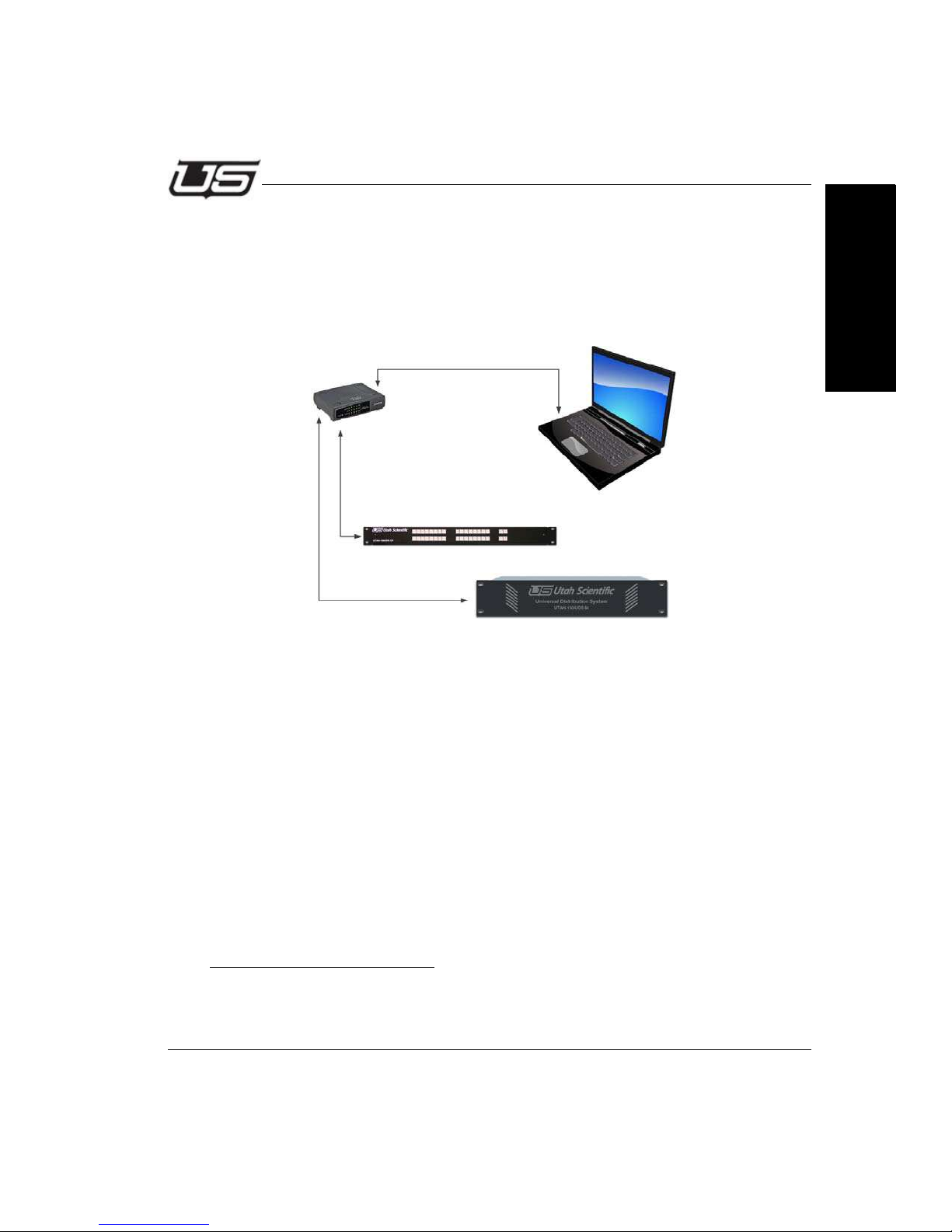
UTAH-100/UDS Network Configuration
UTAH-100/UDS Network Configuration
New Configuration on Independent Network
This scenario consists of a router and a panel working in a stand-alone mode with one
or more PC to complete an independent, stand alone network.
Section 2
FIGURE 1.
New configuration on an independent network is relatively simple, involving Ethernet
connection between the PC and devices (router and panel) only, as a stand alone
network. Simply connect all devices together as shown in Figure 1 for basic setup. In
this case you will only need to set the PC address to the same subnet as the router
and panel. This will facilitate applet operation and table configuration. The following
default IP addresses (below) ship from the factory. The numbers will be consecutive in
the case of multiple panels; i.e., .182, 183, etc.
Routers - 192.168.5.180
Panel - 192.168.5.181
To change the devices to use non default addresses, see New Configuration on an
Existing Network (next). Also note, the PC and devices (router and panel) must
occupy the same subnet.
tance if no default subnet appears.
1. All routers and panels require separate IP addresses.
Section 2 2-3
1
See your network administrator for configuration assis-
Page 50

Network Configuration
Online instruction is also available by accessing the HTML help file located within the
applets, which will also provide details for setup and configuration of the router and panel
tables.
2-4 Network Configuration
Page 51
UTAH-100/UDS Network Configuration
New Configuration on an Existing Network
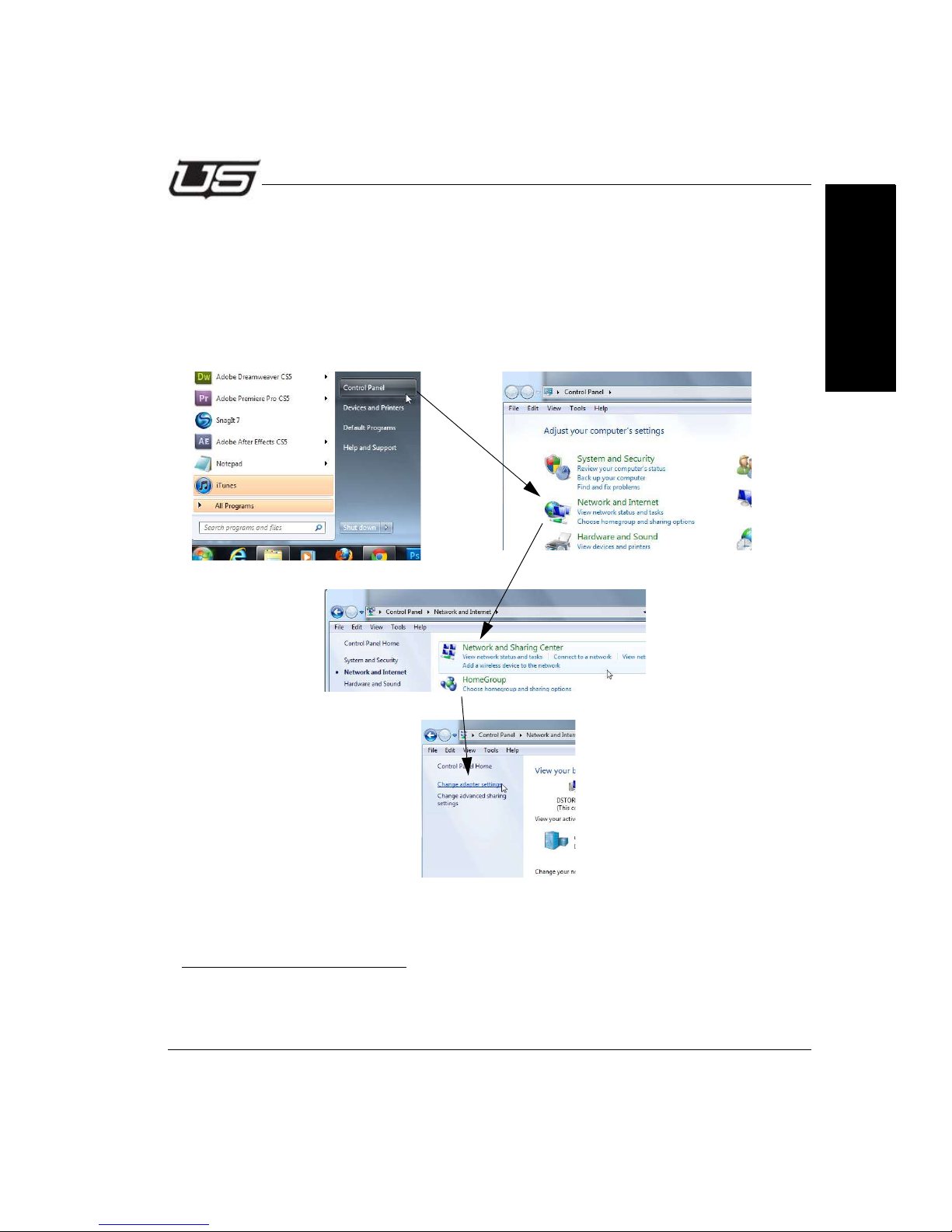
This procedure describes new configuration on an existing network. Use this routine if you
need to modify the router or panel’s network parameters. The steps below are based on
the default set of parameters.
On the PC, click Control Panel, Network and Internet, Network Sharing Center, then
Change Adapter Settings.
1
Section 2
FIGURE 2.
1. These steps are based on Windows 7 operation.
Section 2 2-5
Page 52
Network Configuration
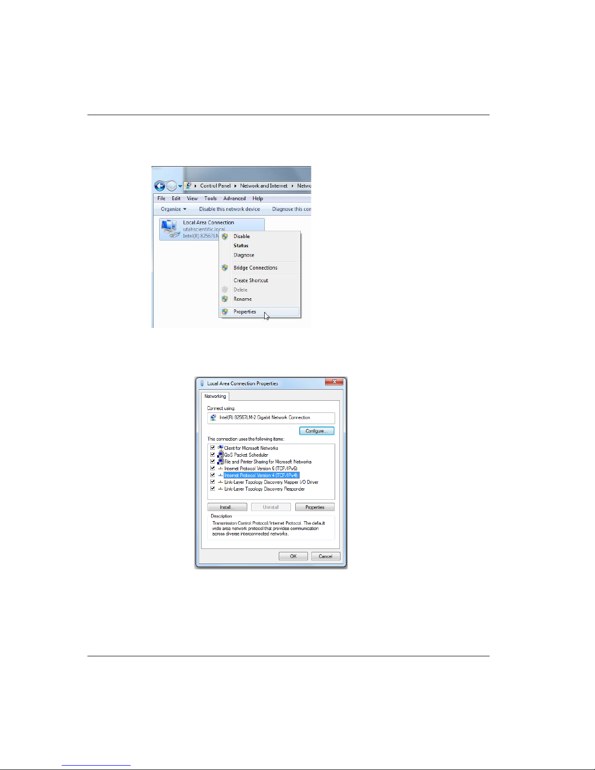
When the following window appears, right-click the icon to produce the drop-down menu, then
select Properties.
FIGURE 3.
The following window will appear.
FIGURE 4.
2-6 Network Configuration
Page 53
UTAH-100/UDS Network Configuration
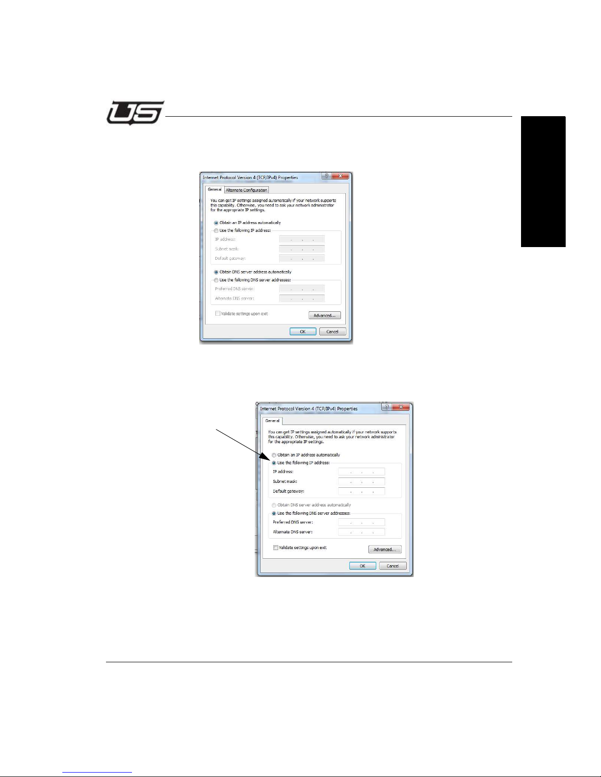
Select Internet Protocol Version 4, then click the Properties button. The following window will appear.
FIGURE 5.
Click the second radio button down to set a static IP address.
Section 2
FIGURE 6.
Section 2 2-7
Page 54
Network Configuration
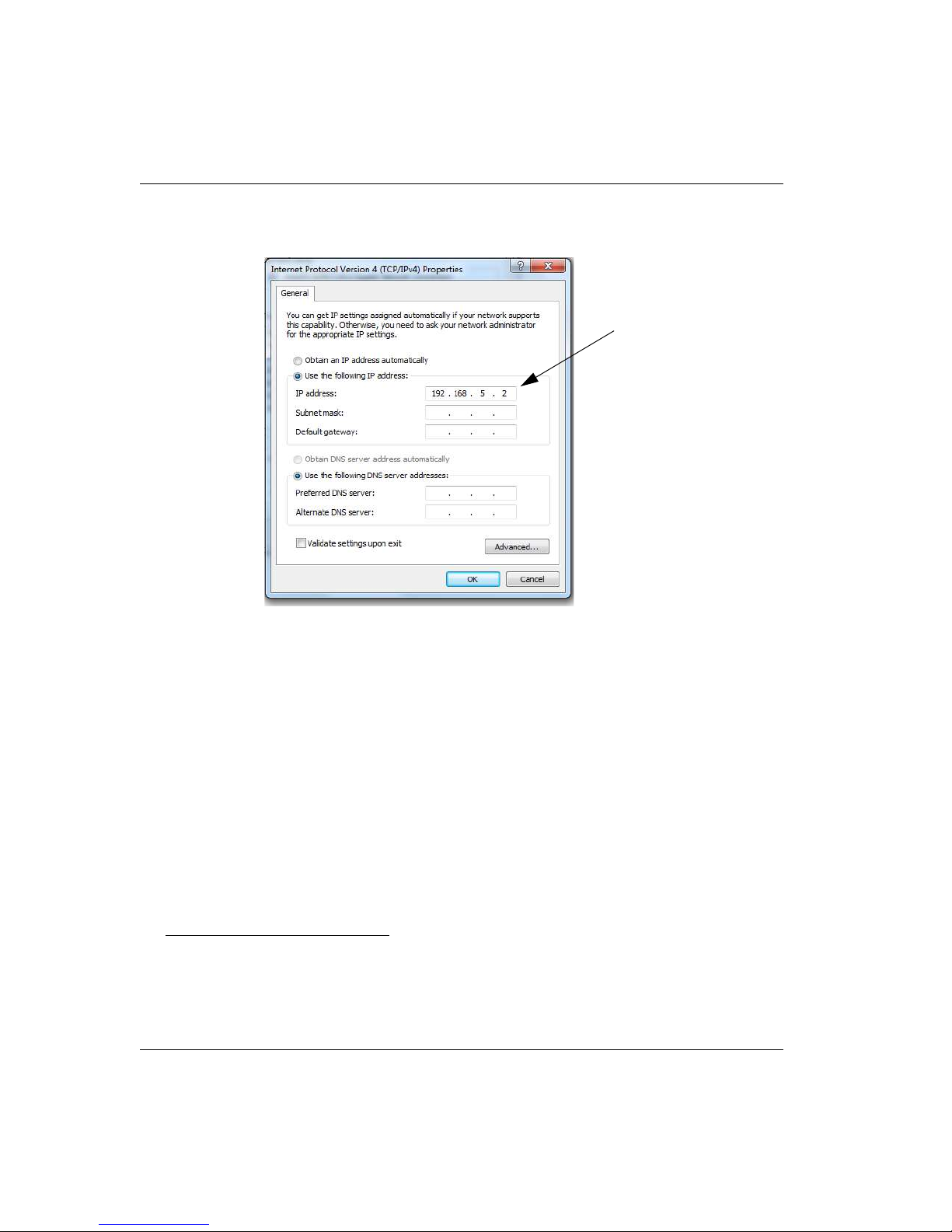
Enter the following address into the indicated cell (192.168.5.2)1
FIGURE 7.
Accept the Subnet mask default, then click OK.
Now connect your PC or laptop to the router with a standard Ethernet cable.
Note: A crossover cable (typically used with an Ethernet connection) is not
necessary as the signal ‘switch’ is done internally.
1. This is the subnet default address. You can substitute the last digit if required for your system. If your system
contains a completely different subnet for the PC, routers, and panels, substitute the correct addresses where
applicable.
2-8 Network Configuration
Page 55
Router Applet Activation and Configuration
Router Applet Activation and Configuration
Launch your preferred browser and complete the following steps:
a. Log into the Router Applet by entering 192.168.5.180 into your browser’s
URL line (default). If your router is using a different address than the default,
enter it into the browser.
NOTE: If the applet does not activate, try pinging the system by opening your command
prompt and typing the router’s IP address (address number ending in .180) to determine
whether or not the connection is good. If you are unable to ping the device, check the connections or see the network administrator for additional help.
In addition, if you are unsure of the IP address, you may need to default the router to the factory IP address of 192.168.5.180.
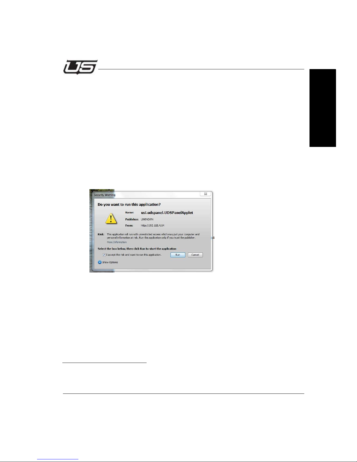
b. Accept the following advisory (checkbox) then click Run to continue
1
Section 2
FIGURE 8.
1. IMPORTANT: You must use Java version 7 or later.
Section 2 2-9
Page 56
Network Configuration
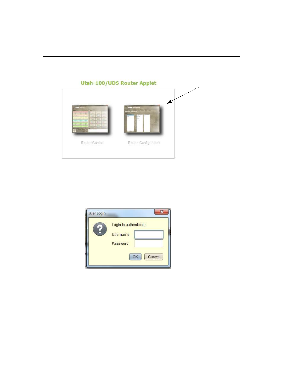
c. When the Router icons appears, select “Router Configuration”.
FIGURE 9.
Note: You will only be able to connect if the browser window (shown in Figure 9) indicates
“Applet ready for login.”
d. Enter Username “admin” (default) - in the username entry box
e. Enter Password “admin” (default) - in the password entry box
2-10 Network Configuration
Page 57
Router Applet Activation and Configuration
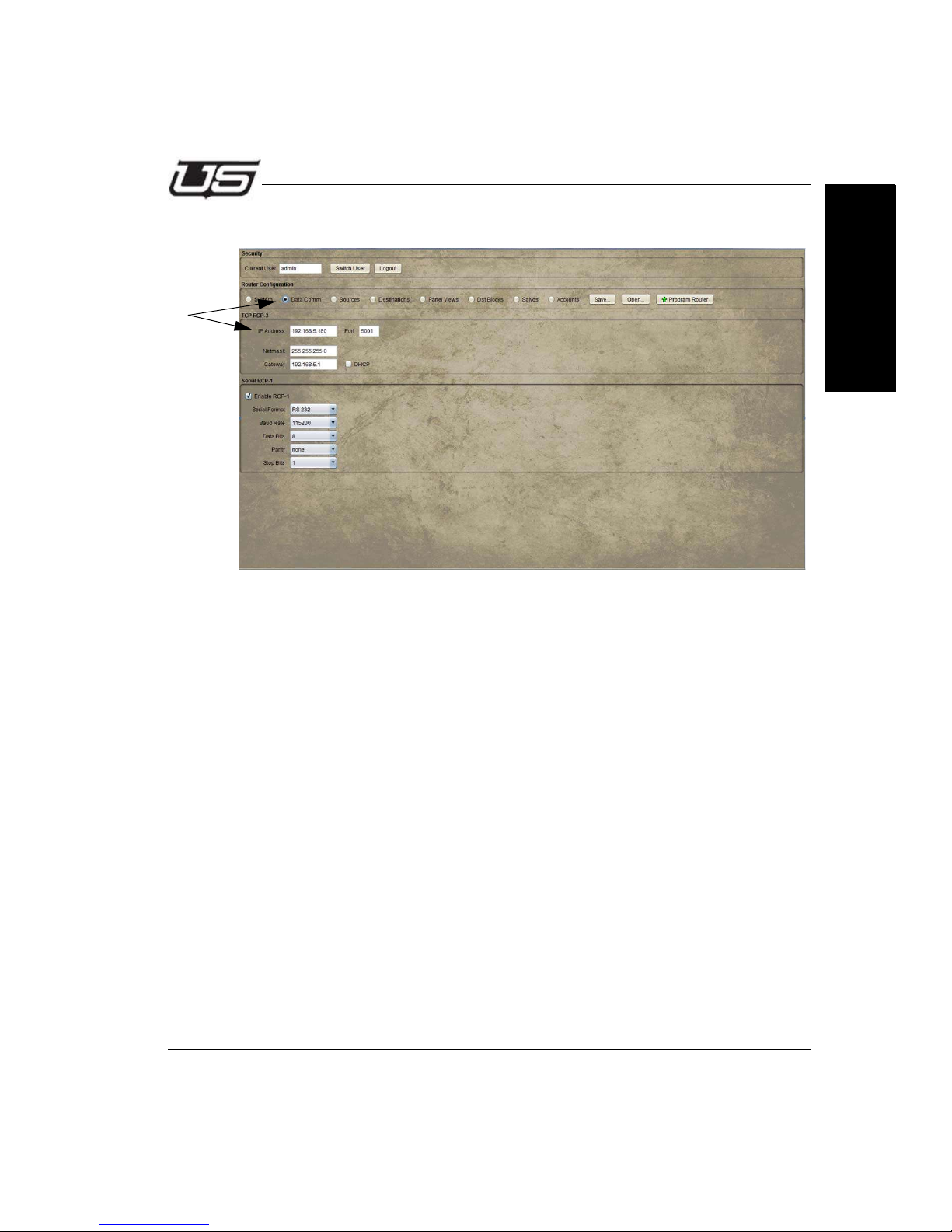
f. Click the Data Comm (radio button) to change the network configuration.
FIGURE 10.
Note: The program will display the router’s IP address (IP Address cell,
above). It is important however that Net mask and Gateway remain constant
among all devices, and to keep the DHCP box unchecked.
Section 2
g. Enter the desired IP address in the space provided.
h. Verify the Port setting of 5001.
i. Make sure the DHCP box is unchecked.
j. Click the “Program Router” button when the network configuration is
complete.
k. A dialog will appear prompting you to reset the device. To make the IP
changes active, reset the router by pressing (and quickly releasing) the small
button at the far right side of the control module on the back of the router.
Note: There is no need to restart the browser when the rout er is rese t.
Once the above steps are complete, the router can be placed on the target network and
configured as needed.
Section 2 2-11
Page 58
Network Configuration
click here to log in
no router connected
Panel Applet Activation and Configuration
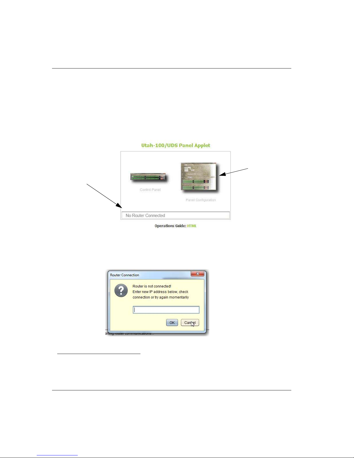
Make sure the panel is plugged into the same network as the PC, and that the PC is set to the
same subnet as the panel. This procedure allows the configuration from the Panel Applet in
the absence of a physical router connection.
Log into the Panel Applet first by bringing up a web browser and entering 192.168.5.181
(factory default setting) in the URL browser box. Click the Panel Configuration icon to log in, as
shown in the figure below.
FIGURE 11.
In this mode, the Panel Applet dialog will indicate the router’s absence.1
The following dialog will appear (with no router connected).
FIGURE 12.
1. This is a simple operational scenario with no router currently connected. You will be taken directly to the
Configuration screen when the router and panel are simultaneously connected.
2-12 Network Configuration
Page 59
Panel Applet Activation and Configuration
Router
Panel
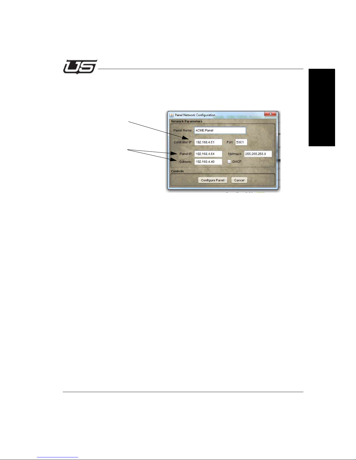
Since there is no router connected, click Cancel to dismiss this dialog.
The following window will appear, which will give you an opportunity to designate the
necessary configuration detail.
FIGURE 13.
The above illustration contains a default IP address (your address may be different).
The Controller IP corresponds to the router address, while the Panel IP and Gateway
are associated with the panel that you are using. Enter the correct addresses as
needed.
Section 2
Click Configure Panel when the correct addresses are in place, then reset the
system.
A dialog will appear prompting you to reset the device. To make the IP changes
active, cycle the power to the panel or reset the panel by pressing (and quickly
releasing) the small button at the far right side of the control module (rear of panel).
Once the above steps are complete, the panel can be placed on the target network
and configured as needed.
You can now log in to the router and panel applets to configure you system as needed
using the newly configured IP addresses. The default username and password is
admin, in both cases. Once you have logged in, click the configuration icons to
activate the configuration dialogs.
For additional assistance, please contact Utah Scientific Customer Service - 1(800)
447-7204.
Section 2 2-13
Page 60

Network Configuration
2-14 Network Configuration
Page 61

Router Configuration
Section 3
Section 3
UTAH-100/UDS Browser Utility
The Router Applet
Router Configuration
Router Configuration is activated by launching the browser applet (using the supplied
default IP address). This section contains the steps involved in activation and operation of
the UTAH-100/UDS Router Applet.
Section 3 3-1
Page 62
The Router Applet
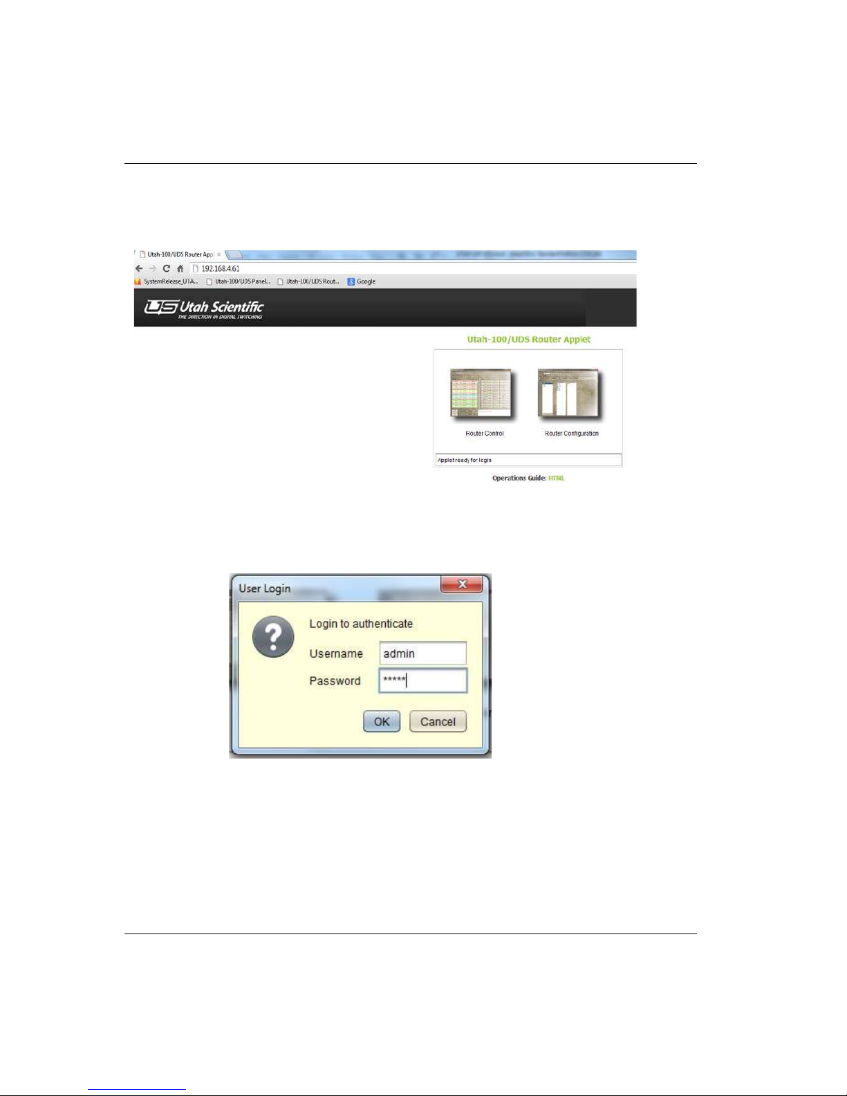
The Router applet must be connected to the actual router to communicate properly. Once the
necessary hardware is in place, start the application with the provided IP address, then launch
the applet by clicking the Router Configuration icon.
Figure 3-1.
You will be prompted to log in with your username and password. The default is
admin/admin).
Figure 3-2.
3-2 The Router Applet
Page 63
Router Configuration
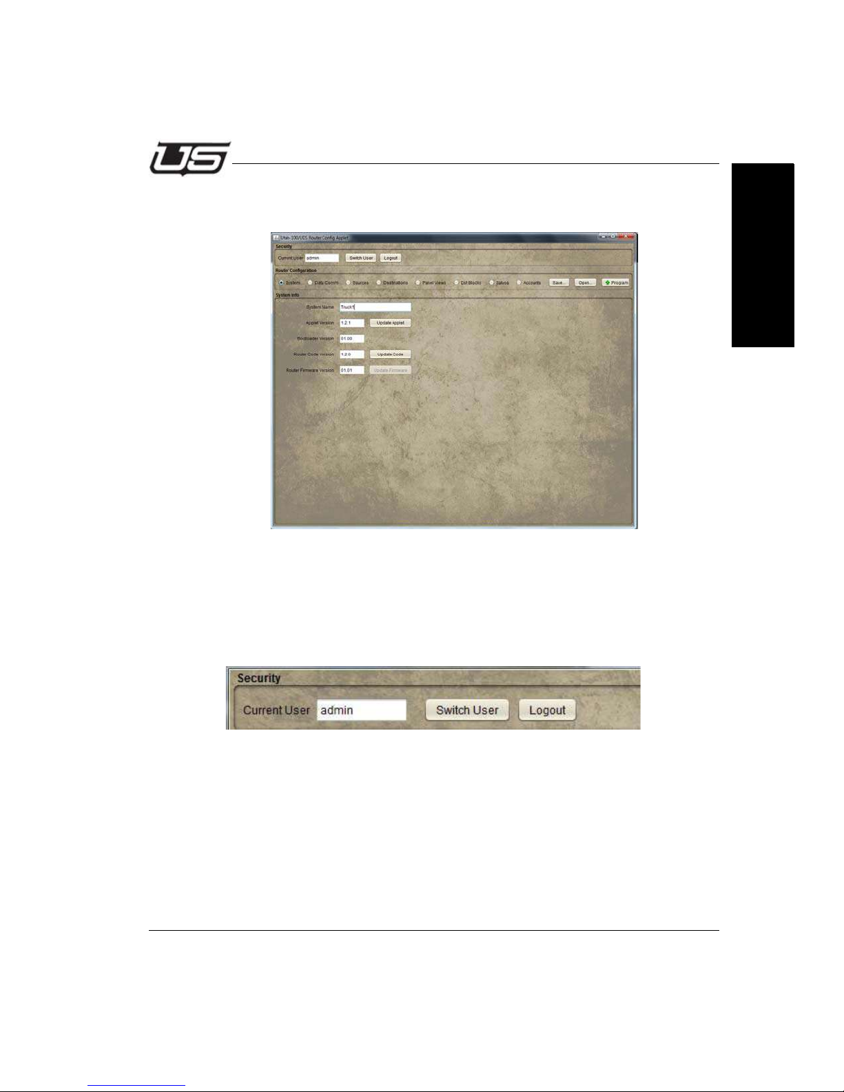
This will activate the setup window. During a successful login, all associated accounts are
loaded into the system at the time of the initial launch (Current User).
Figure 3-3.
Section 3
Security
The default user is listed in the 'Current User' cell. You can change users from the list of
previously designated users (Switch User button). Users are selected from this dialog but
not configured.
Figure 3-4.
Section 3 3-3
Page 64
The Router Applet
Data Comm
TCP RCP-3 (Network)
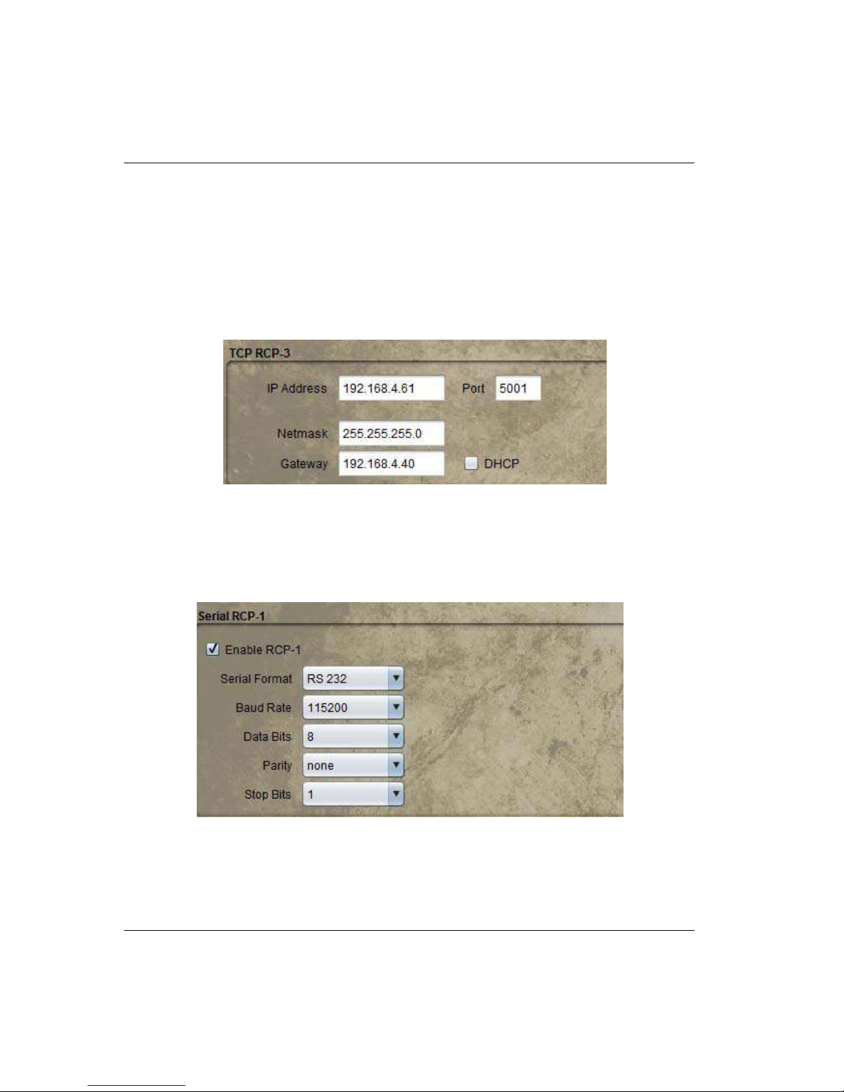
This dialog is used to set Device Communications parameters. Network IP address,
netmask, and gateway parameters are edited at this location along with the RCP-3 port
setting. Alternatively, you can select DHCP to automatically set network parameters. The
only way to verify the IP address setting in DHCP mode is to access the DHCP server.
Figure 3-5.
Serial RCP-1
This area allows for enabling or disabling RCP-1 (checkbox) and assigning the parameters
associated with serial format, baud rate, data bits, parity, and stop bits.
Figure 3-6.
3-4 The Router Applet
Page 65
Router Configuration
DHCP
In certain circumstances the default IP address is unusable and DHCP connectivity is expected.
Click the DHCP box to activate the connection. The address cells will gray out when the box is
clicked. The only way to verify the IP address setting in this mode is to monitor the DHCP server
via serial connection.
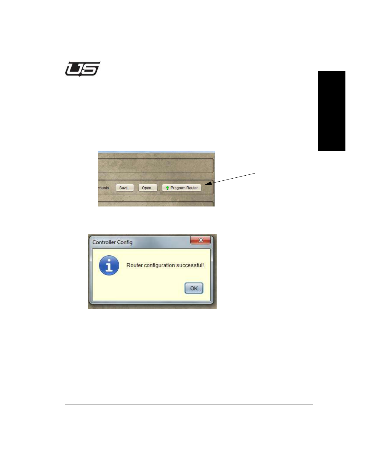
Once network modifications are complete (IP changes), click the Program Router button.
Figure 3-7.
The ‘configuration successful’ dialog will appear.
Section 3
Figure 3-8.
Section 3 3-5
Page 66
The Router Applet
Sources
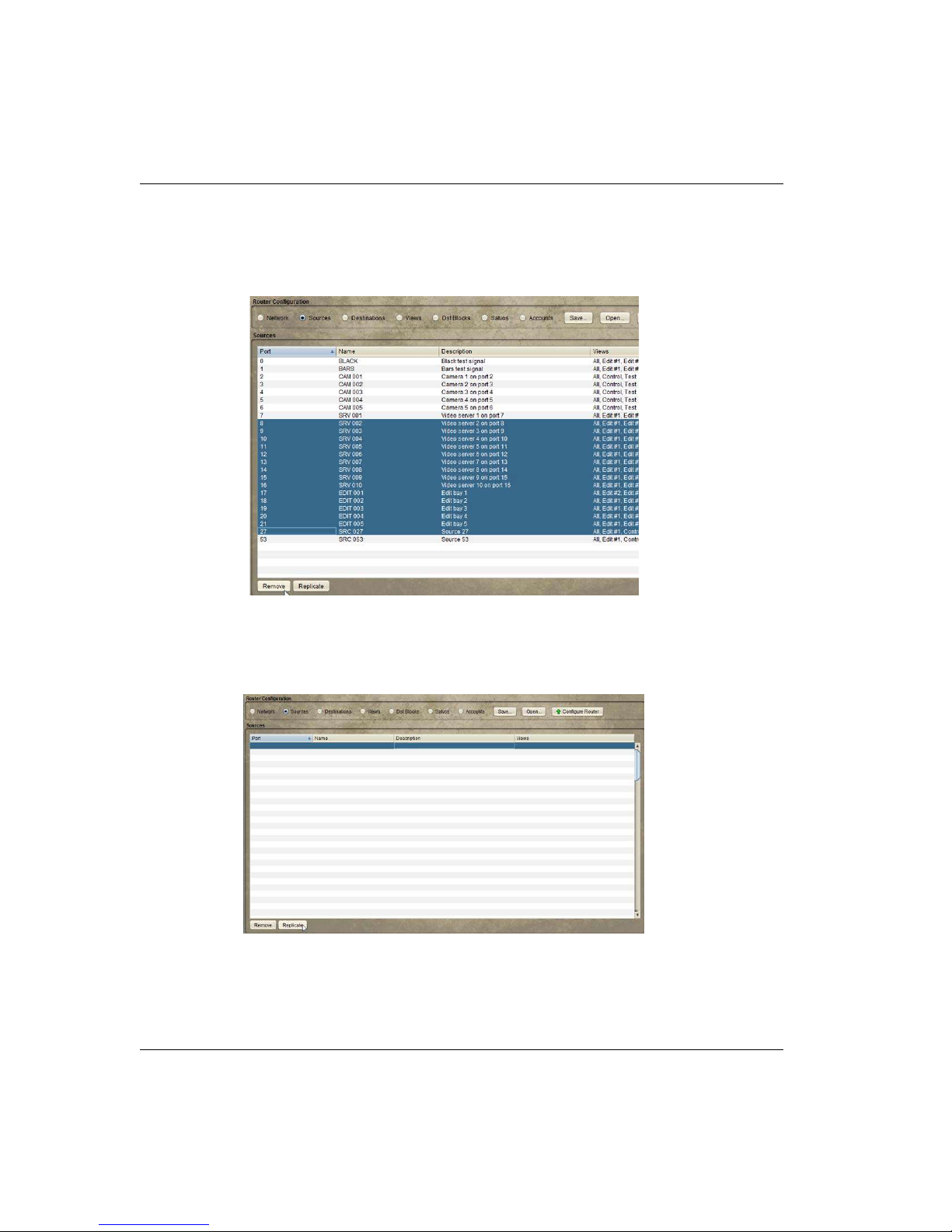
The program defaults with all sources configured. Since this is not the likely desired
configuration, highlight the unwanted sources and click the Remove button.
Figure 3-9.
Source Creation
New Sources are defined and added by clicking the Replicate button.
Figure 3-10.
Also, the Source table can be sorted by clicking on the desired column header.
3-6 The Router Applet
Page 67
Router Configuration
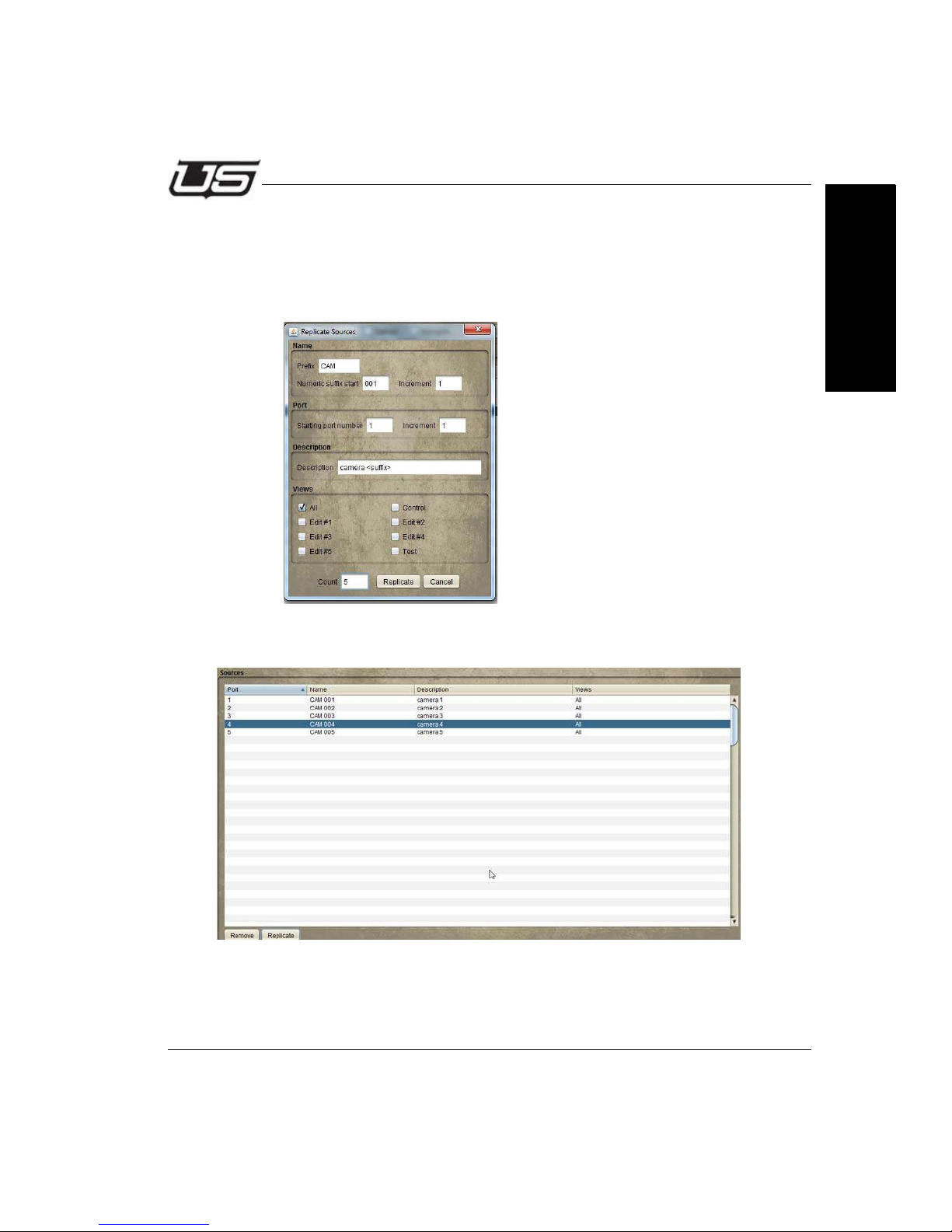
In this example, the prefix is the three character descriptor for camera. Numeric suffix start is the
3 digit end definer associated with the device. Increment, and starting port number are all
assigned as number ‘1’. The Description is a long form identifier, with ‘suffix’ placed inside ‘less
than’ and ‘greater than’ symbols to allow the system to properly increment the devices in the
listing. ‘All’ views are selected, and the number of devices requested for the list count is ‘5’.
Figure 3-11.
Section 3
The resulting list display is illustrated below.
Figure 3-12.
Section 3 3-7
Page 68
The Router Applet
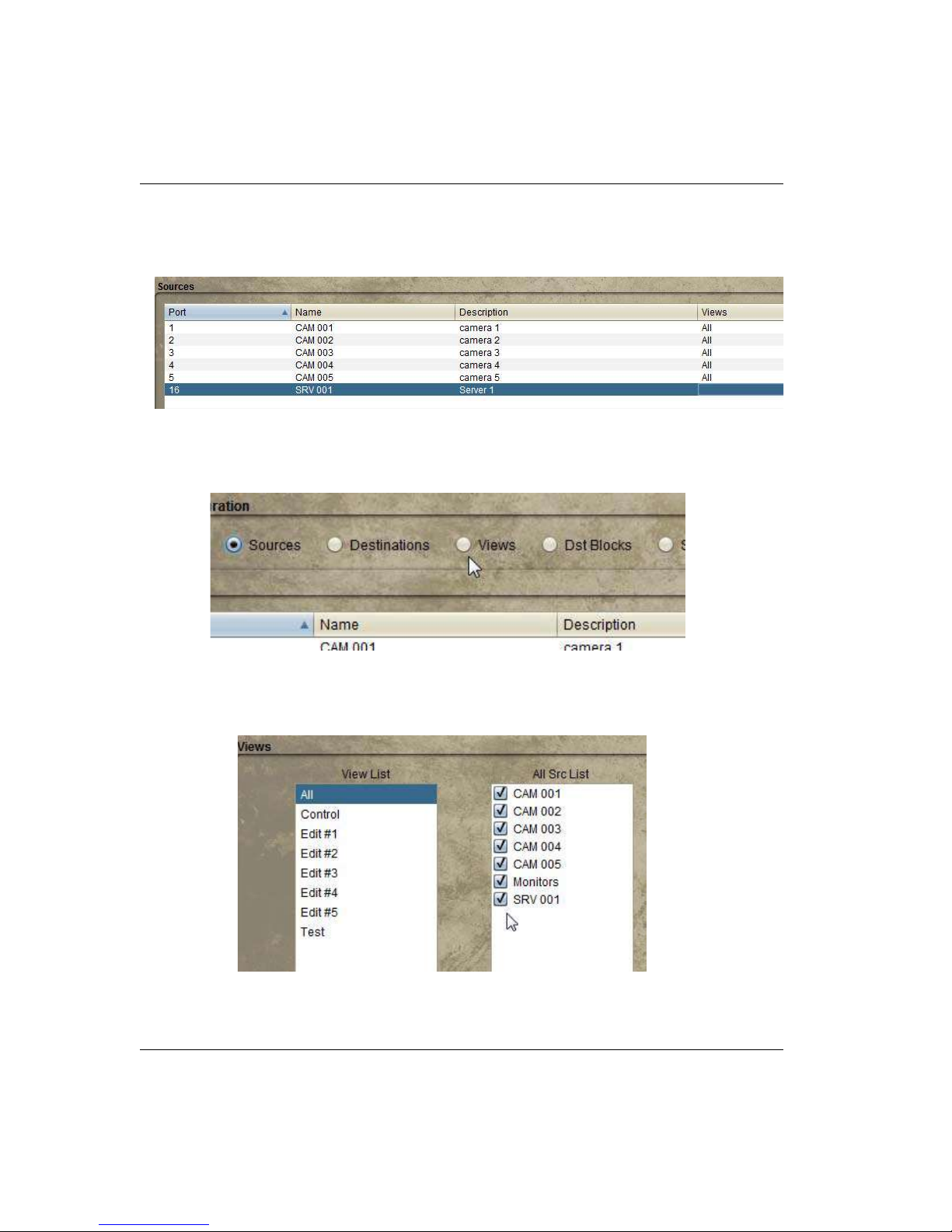
Source creation from within the list
Highlight the line and enter the definitions for Port, Name, and Description.
Figure 3-13.
Using this option to add Sources will not allow you to manually enter the View method. Click
the View radio button to make this modification.
Figure 3-14.
Click the checkbox associated with the new Source, then highlight the desired view type
within the View list.
Figure 3-15.
3-8 The Router Applet
Page 69
Router Configuration
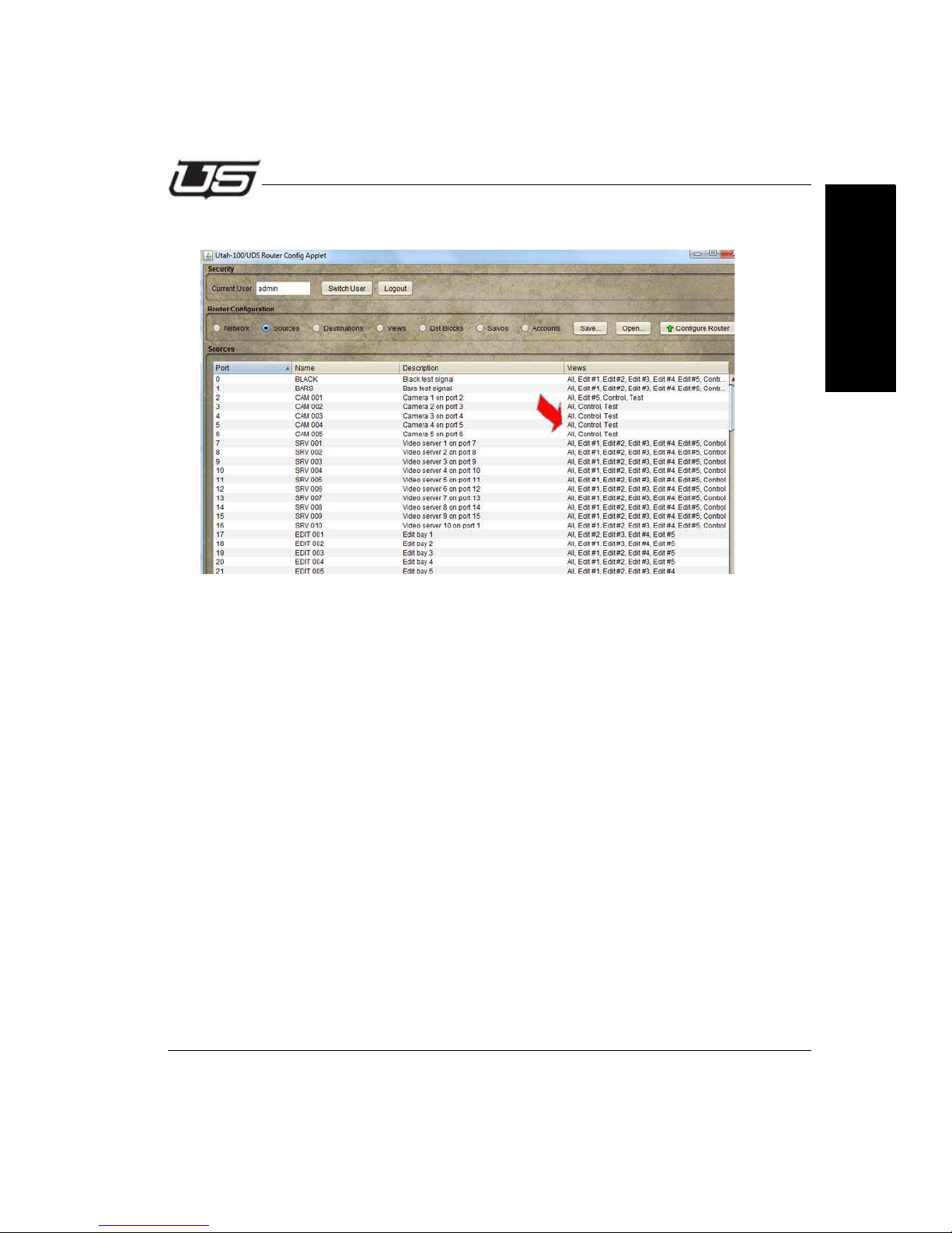
Your new view will be associated when you return to the Sources window.
Figure 3-16.
Section 3
Section 3 3-9
Page 70
The Router Applet
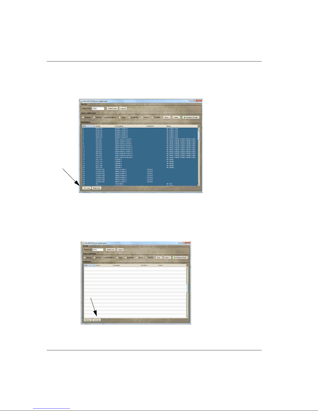
Destinations
The program defaults with all destinations configured. Since this is not the likely desired
configuration, highlight the unwanted sources and click the Remove button.
Figure 3-17.
Destination creation
New Destinations are defined and added by clicking the Replicate button, or by entering
data in the table directly. In addition, the Destination table can be sorted by clicking the
desired column header.
Figure 3-18.
3-10 The Router Applet
Page 71
Router Configuration
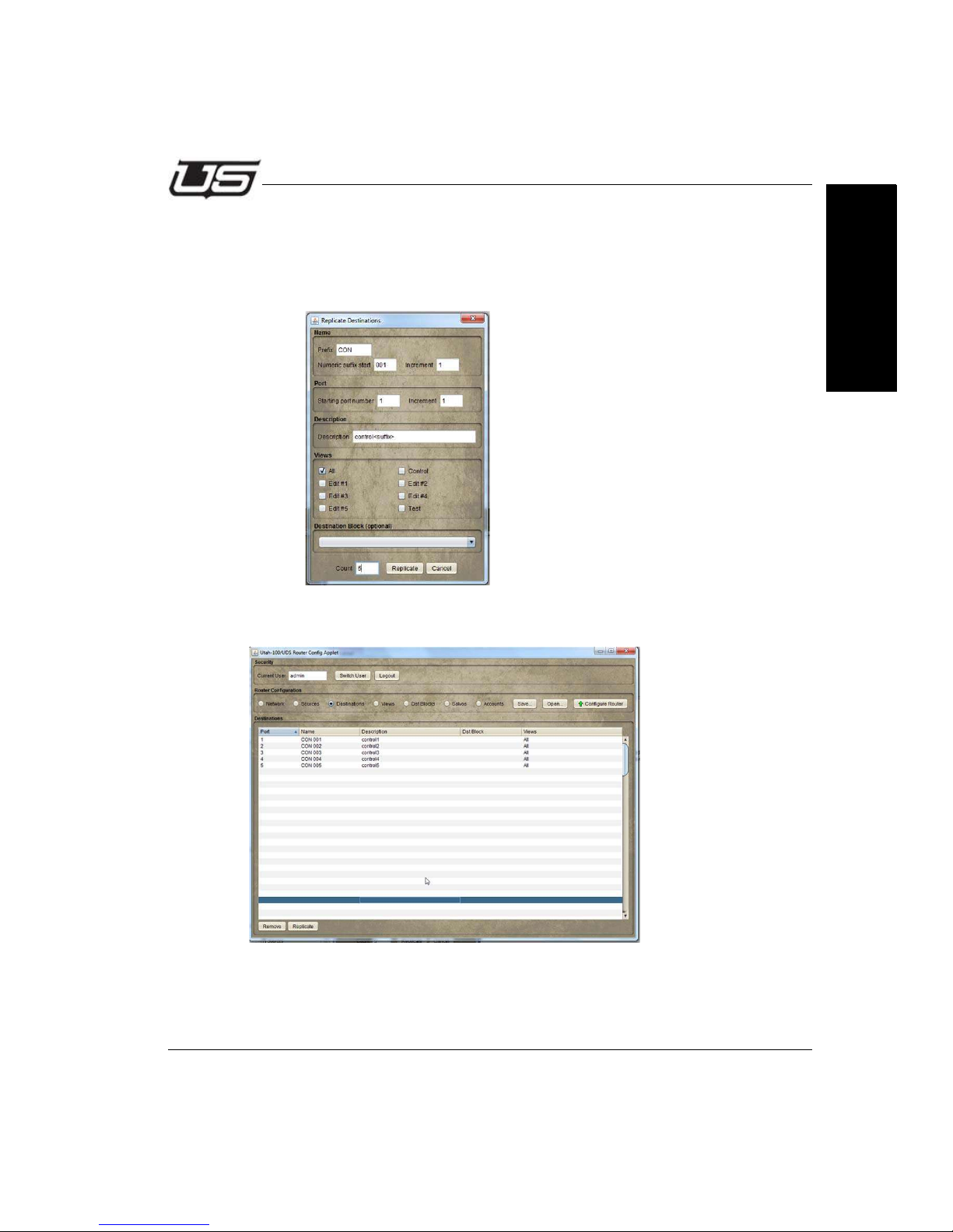
In this example, the prefix is the three character descriptor for camera. Numeric suffix start is the
3 digit end definer associated with the device. Increment, and starting port number are all
assigned as number ‘1’. The Description is a long form identifier, with ‘suffix’ placed inside ‘less
than’ and ‘greater than’ symbols to allow the system to properly increment the devices in the
listing. ‘All’ views are selected, and the number of devices requested for the list count is ‘5’.
Figure 3-19.
Section 3
The resulting list display is illustrated below.
Figure 3-20.
Section 3 3-11
Page 72
The Router Applet
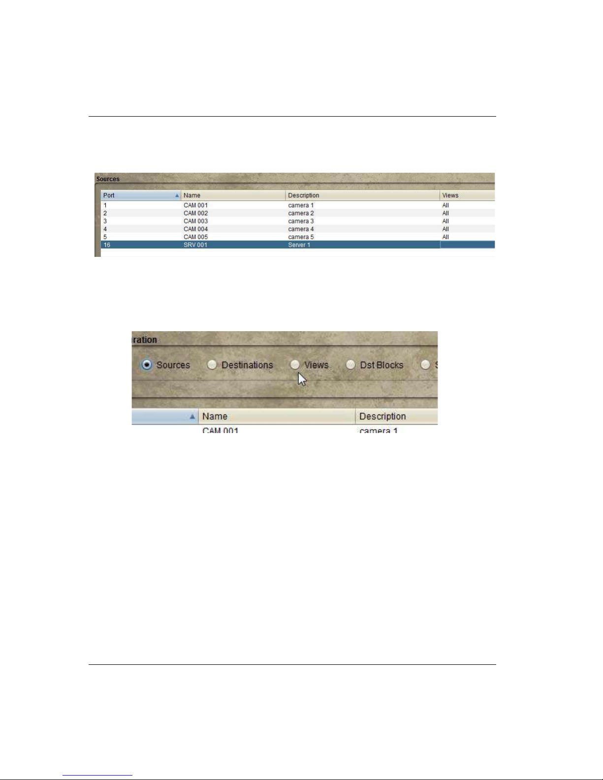
Destination Creation from Within the List
Highlight the line and enter the definitions for Port, Name, and Description.
Figure 3-21.
Do this to overwrite the lines contents when the cursor becomes active.
Using this option to add Destinations will not allow you to manually enter the View method.
Click the View radio button to make additional modifications.
Figure 3-22.
3-12 The Router Applet
Page 73
Router Configuration
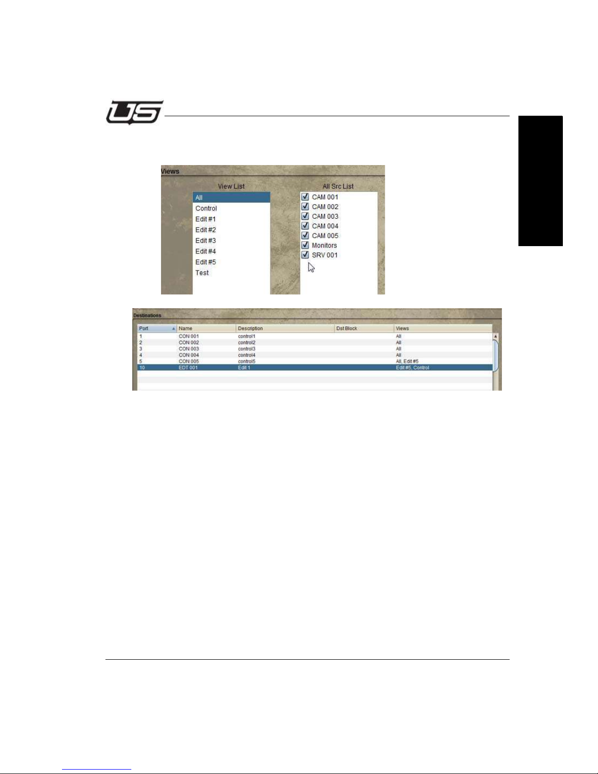
Click the checkbox associated with the new Destination, then highlight the desired view
type within the View list.
Section 3
Figure 3-23.
You can also click the Destinations radio button and ‘Replicate’ in the same manner as
with Sources. This involves adding Destinations to the list in the correct sequence.
The Replicate dialog window contains a pop down menu at the bottom, which will contain
any previously created Destination blocks.
Click the Configure Router button when the needed destination blocks have been
created.
Section 3 3-13
Page 74
The Router Applet
Panel Views
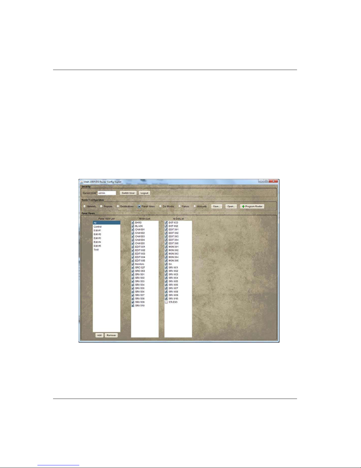
Organizing
The Views selection is a way to organize Sources and Destinations into manageable
groups for the router control window. Views will appear within the Source and Destination
lists immediately after editing.
To facilitate this, click the Panel Views radio button, select the desired View from the list on
the left, then click the checkboxes within the next two devices you would like associated
with the View.
You can also create a whole new view by clicking the Add button at the bottom of the
left-hand list.
Figure 3-24.
3-14 The Router Applet
Page 75
Router Configuration
Sort Parameters
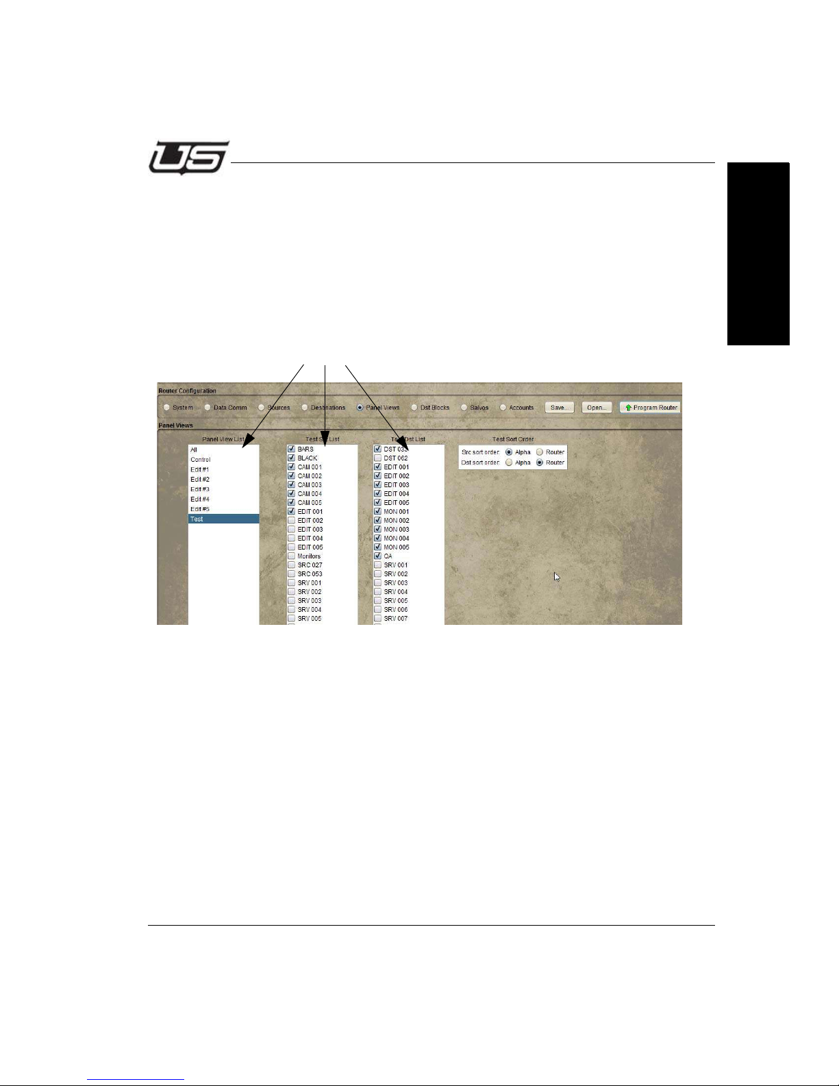
Sorting Option
With Panel Views selected, the Sorting Option is a way to organize Sources and
Destinations into display lists (Router Control applet) based on a router or alphabetic port
designation.
To access the sorting option, click the Panel Views radio button, the parameters you
would like to sort within, then indicate the All Sort Order (Alpha or Router) and click the
Program button.
Section 3
Section 3 3-15
Page 76
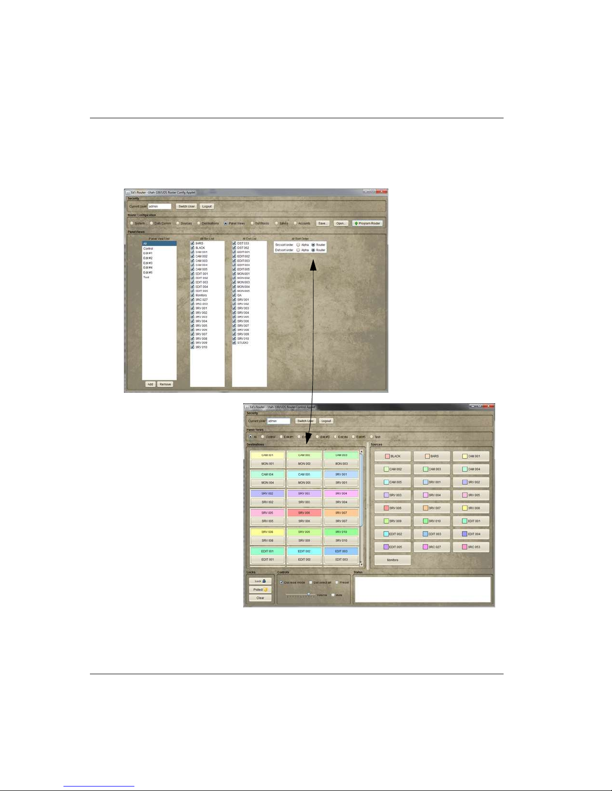
The Router Applet
Router Sort
This is an example of the display that will appear within the Router Control Applet when
Router Sort is indicated (Config Applet). Sorting is completed by router port.
Figure 3-25. Router Sort
3-16 The Router Applet
Page 77
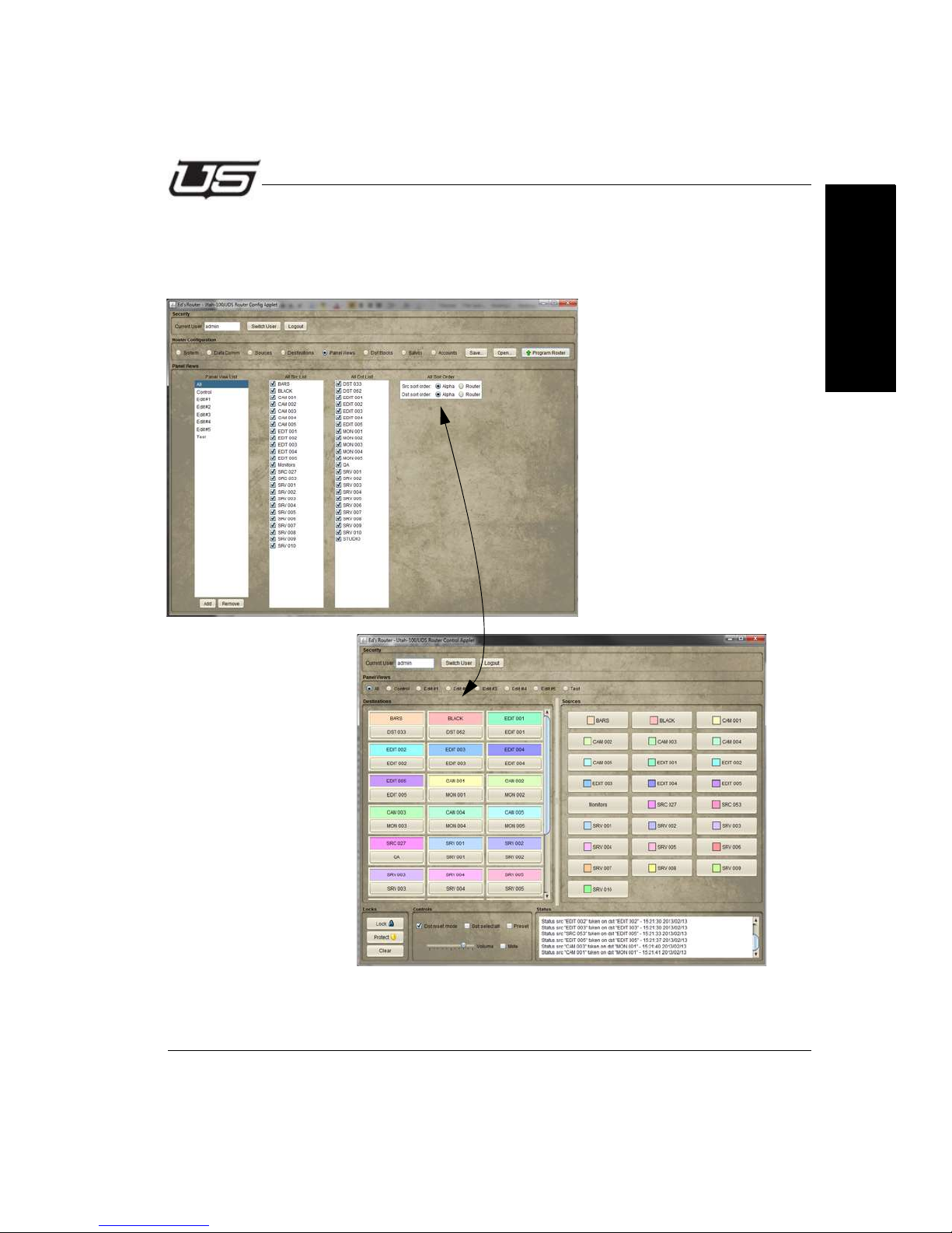
Router Configuration
Alpha Sort
And this is an example of the display that will appear within the Router Control Applet when
Alpha Sort is indicated (Config Applet). Sorting is completed by alpha numeric port.
Section 3
Figure 3-26. Alpha Sort
Section 3 3-17
Page 78
The Router Applet
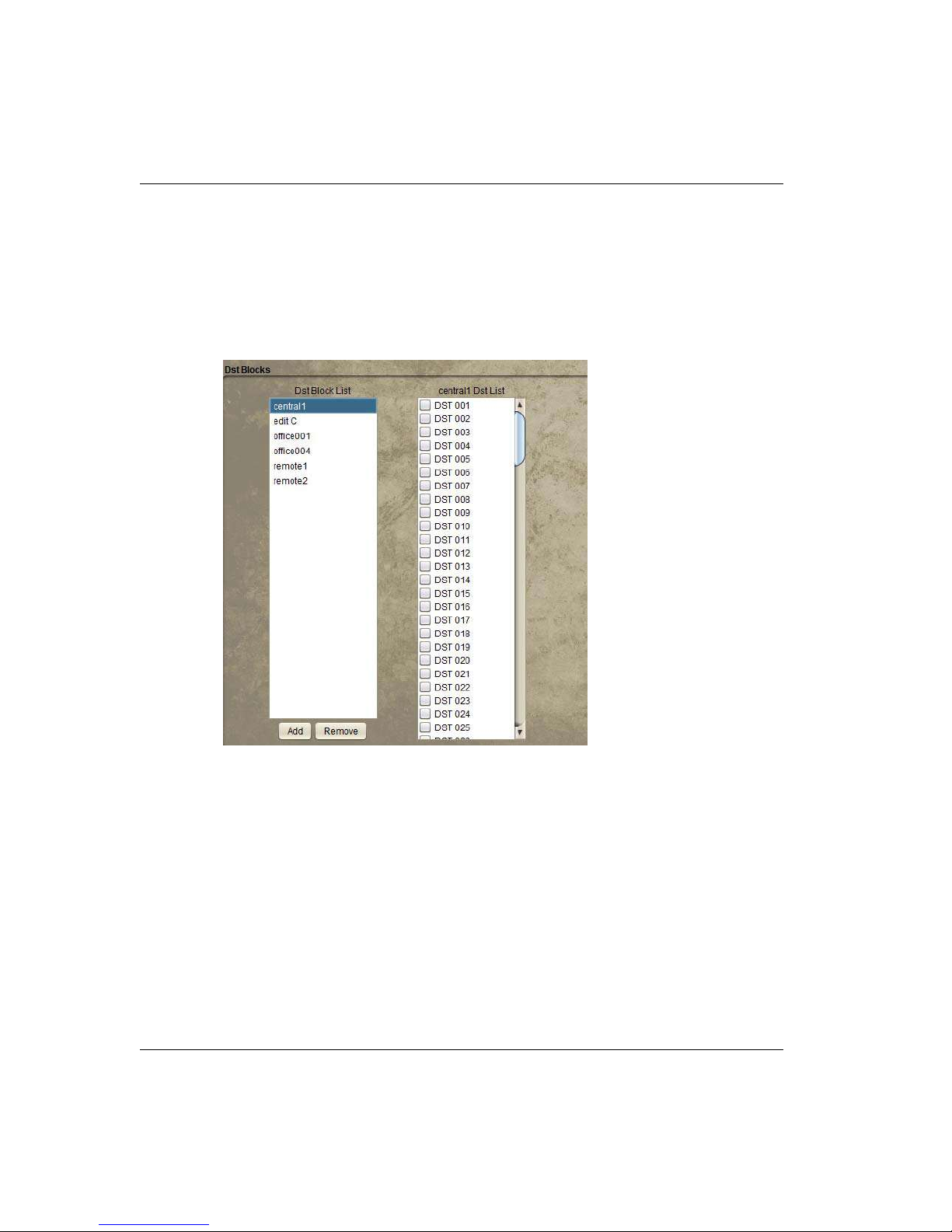
Destination Blocks
The Destination Block is essentially a way to assign a destination grouping as a DA. Any
pre-configured destination blocks will display in the drop down list inside this dialog window.
This saves time by assigning an entire group, or block at once.
Click the Dst Block checkbox to activate this feature. Provide a name when the dialog
appears.
Figure 3-27.
The block will appear as one single destination in the system when a destination block is
created. The new name will appear within the left listing and the options (to include) will
appear within the right listing.
When Takes are made on the DA block, the take source will be immediately switched up to all
of the destinations in the block.
The router will report the total number of takes corresponding to the number of replicated
destinations whenever takes are made on the DA block.
Note: Destinations assigned to specific Destination Blocks cannot be assigned
to additional Destination Blocks. A dialog will appear, asking if you wish
to reassign, in the event this is attempted.
3-18 The Router Applet
Page 79
Router Configuration
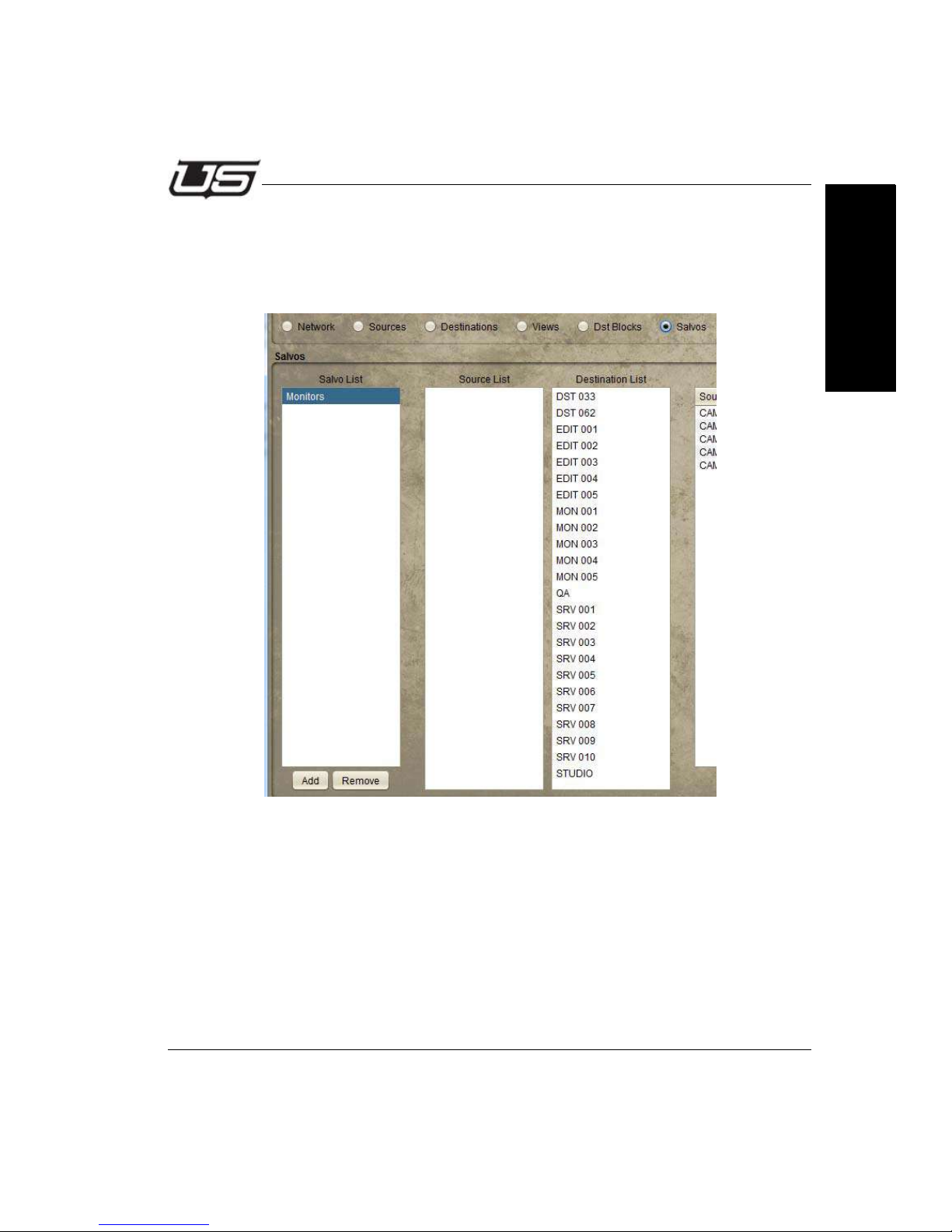
Salvos
The Salvo is a mechanism for storing multiple takes to be conveniently triggered at a later
time. Salvos will appear as new sources in the system and will trigger the configured
takes when selected.
Section 3
Figure 3-28.
Section 3 3-19
Page 80
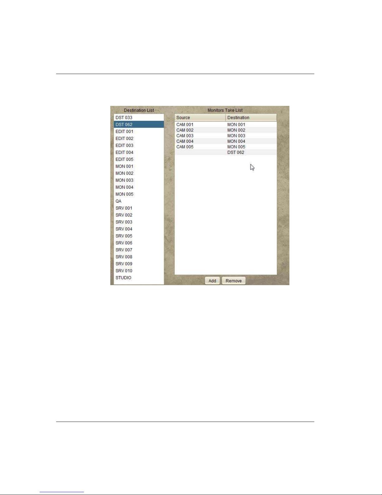
The Router Applet
Select the desired Source and Destination from the lists, then click the “Add” button to
place the new Salvo to the listing on the right.
Figure 3-29.
3-20 The Router Applet
Page 81
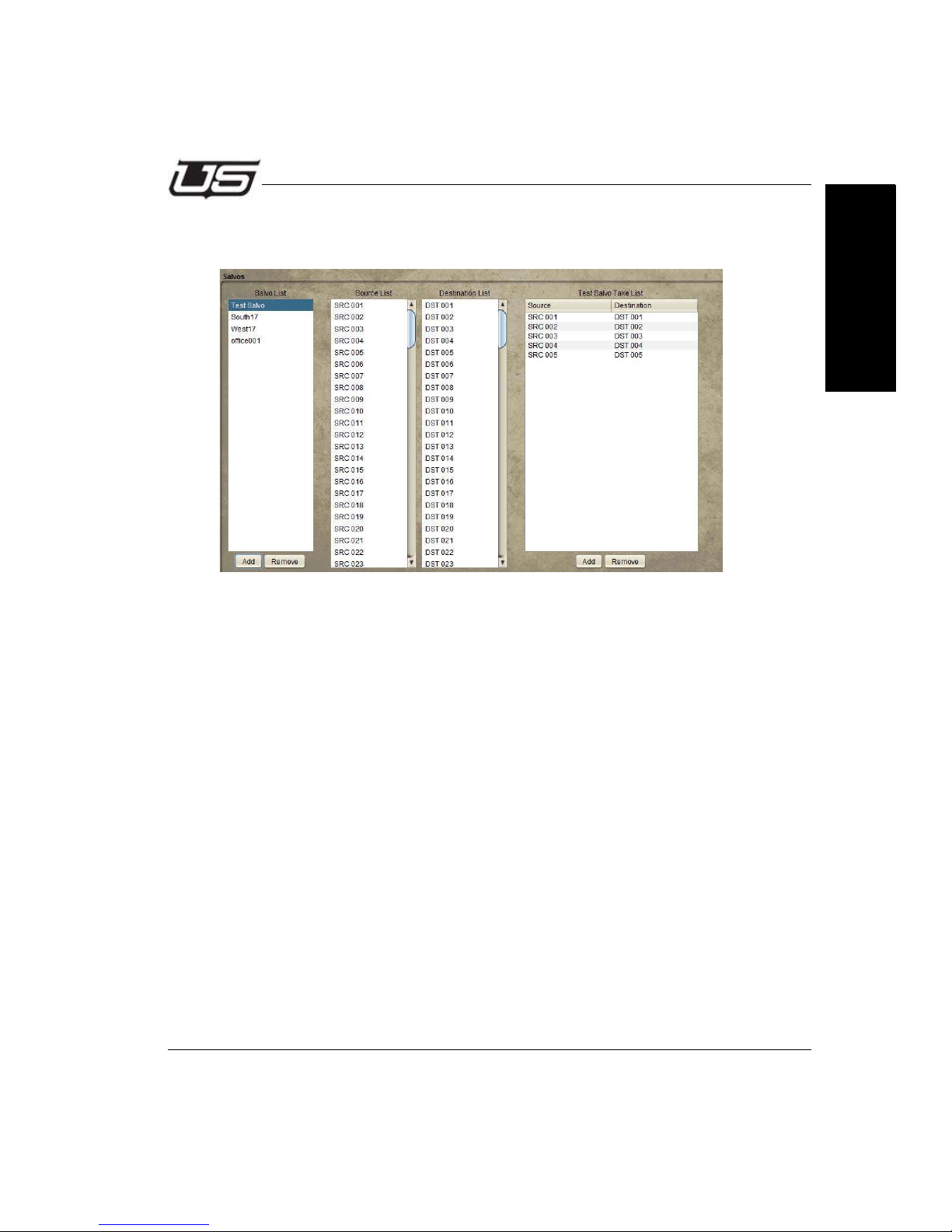
Router Configuration
You can now verify your new Salvo by accessing the View dialog area (View radio button).
Note that a new Source is listed within the corresponding column.
Figure 3-30.
Your new Salvo will also be displayed inside the Router Control applet.
Section 3
Section 3 3-21
Page 82
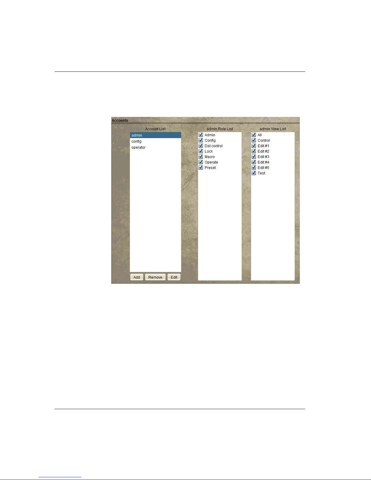
The Router Applet
The ‘UDS System’ defaults with 3 pre-defined use accounts. You can edit the
passwords, modify, delete, or add accounts as needed for your operation.
Accounts
Figure 3-31.
• Roles allow permissions for various system attributes; the actual
creation, modification, or deletion of accounts (admin).
• Config allows router and panel configuration. Dst control allows for
control over the Dst reset and Dst select all checkboxes (Router Control
area).
• Lock gives the associated account control over actual lock status.
• Macro allows macro editing while in preset mode.
• Operate controls the ability to make Takes.
3-22 The Router Applet
Page 83

Router Configuration
• Preset controls the ability to turn preset on or off; Preset ON allows constant
preset activation if needed.
Views to be associated with given accounts are defined by the checkboxes in the
admin View List. While all layouts are available to any user for status view,
destination selection and the ability to make takes are defined within this listing.
Section 3
Figure 3-32.
Section 3 3-23
Page 84
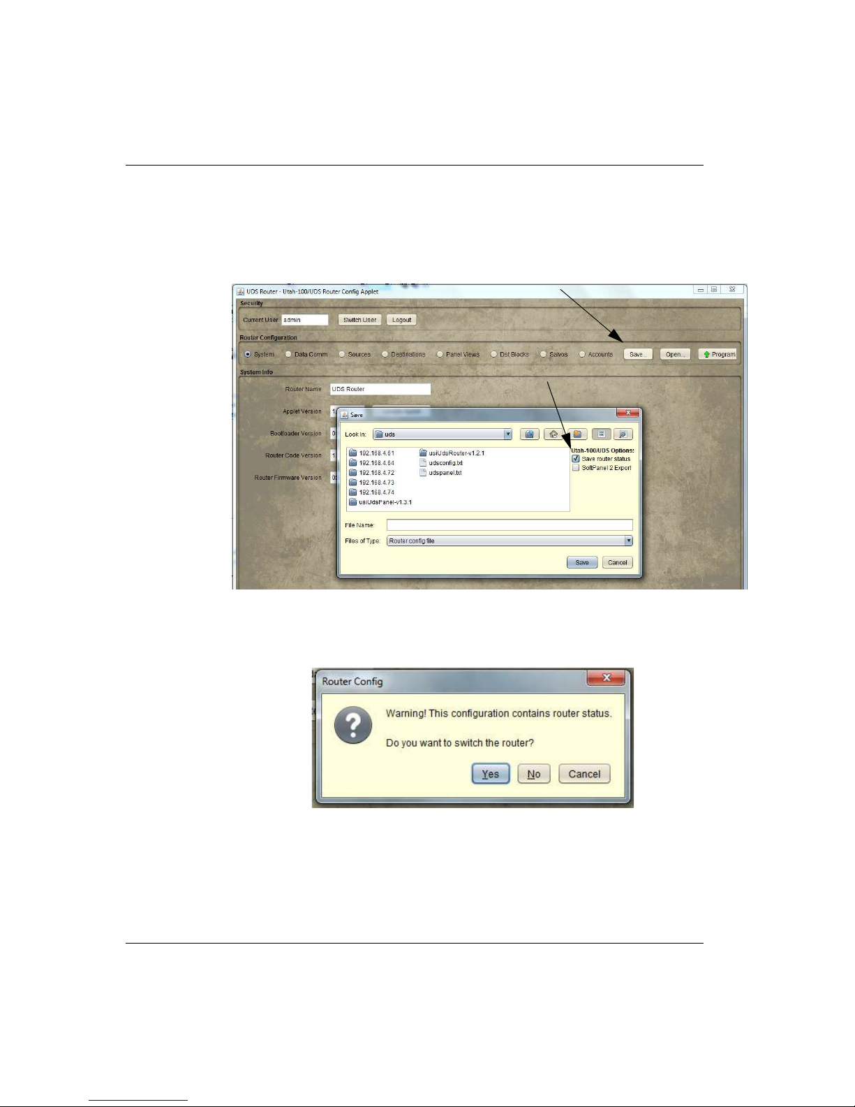
The Router Applet
Save Button
The router configuration is saved to a file on your computer. If you want to save the
current state of the router connections, make sure the corresponding check box is
indicated within the Router Configuration dialog window (right side).
Note: When you program the router (Program Router button), a warning dialog will
appear indicating that the current configuration ‘Contains Router Status - Do you
wish to Switch the Router?’
Clicking ‘No’ indicates the configuration will be saved without the Router.
Clicking ‘Yes’ indicates the configuration is saved and the Router Outputs will be
stored.
3-24 The Router Applet
Page 85
Router Control
Router Control
Source and Destination Management
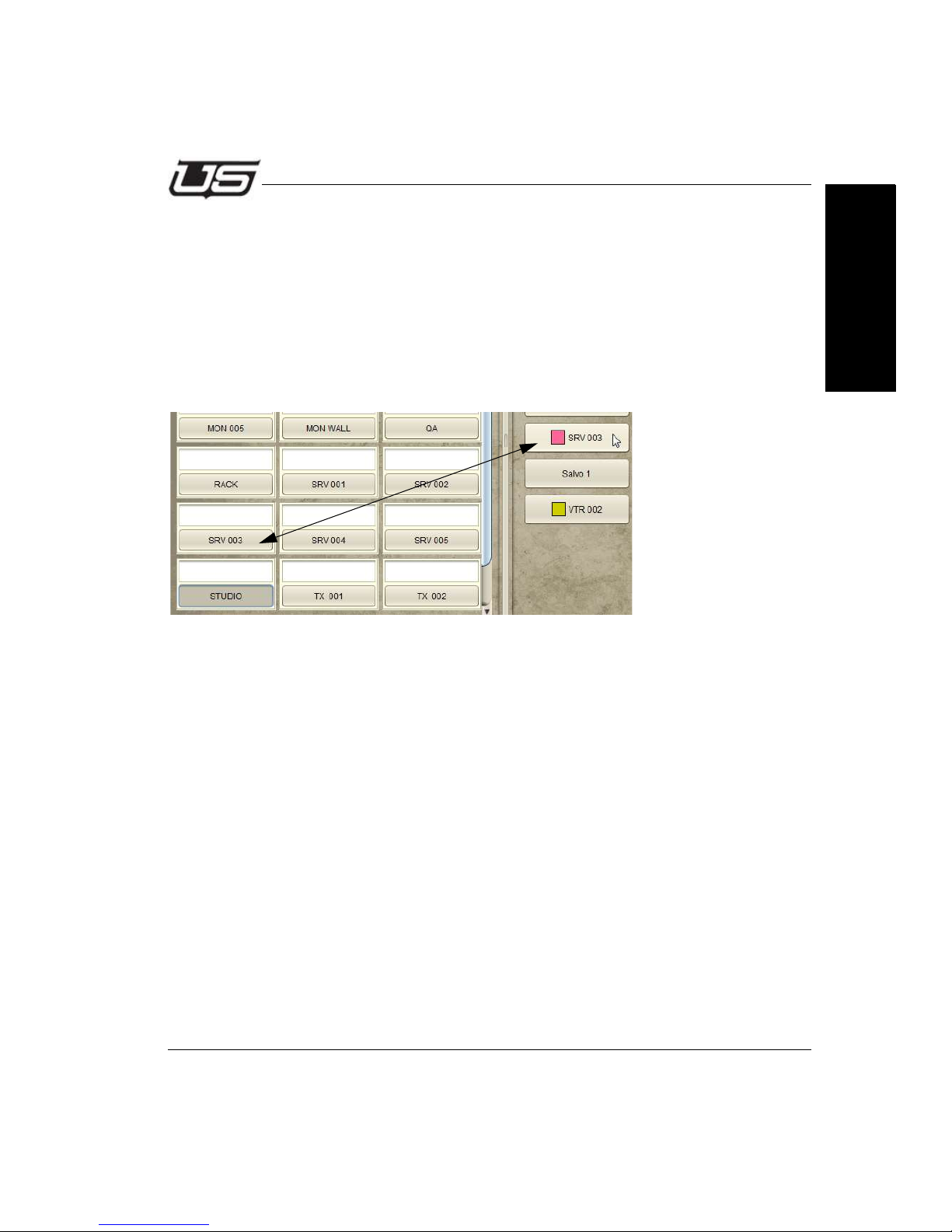
Destination buttons are contained on the left side of the display, with the Source status
indicated above each button.
The Control panel layout (illustrated below) will follow your own panel configuration.
Destinations are selected on the left side of the display by clicking the labeled button, then
the intended Source is selected (clicked) on the right side of the display.
Figure 3-33.
Section 3
Section 3 3-25
Page 86
The Router Applet
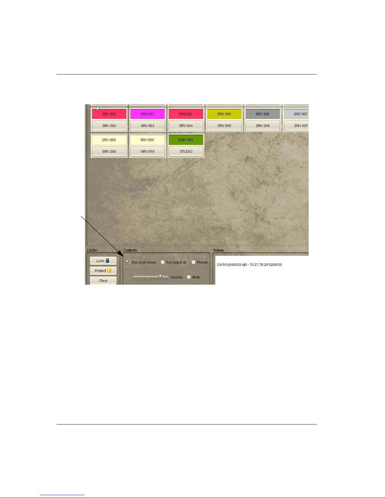
When you select a Destination and make a Take, the Destinations will automatically reset if the
checkbox below is set.
Figure 3-34.
Otherwise the Destinations will remain selected allowing you to make multiple takes on the
same Destinations without having to re-select each one.
3-26 The Router Applet
Page 87
Router Control
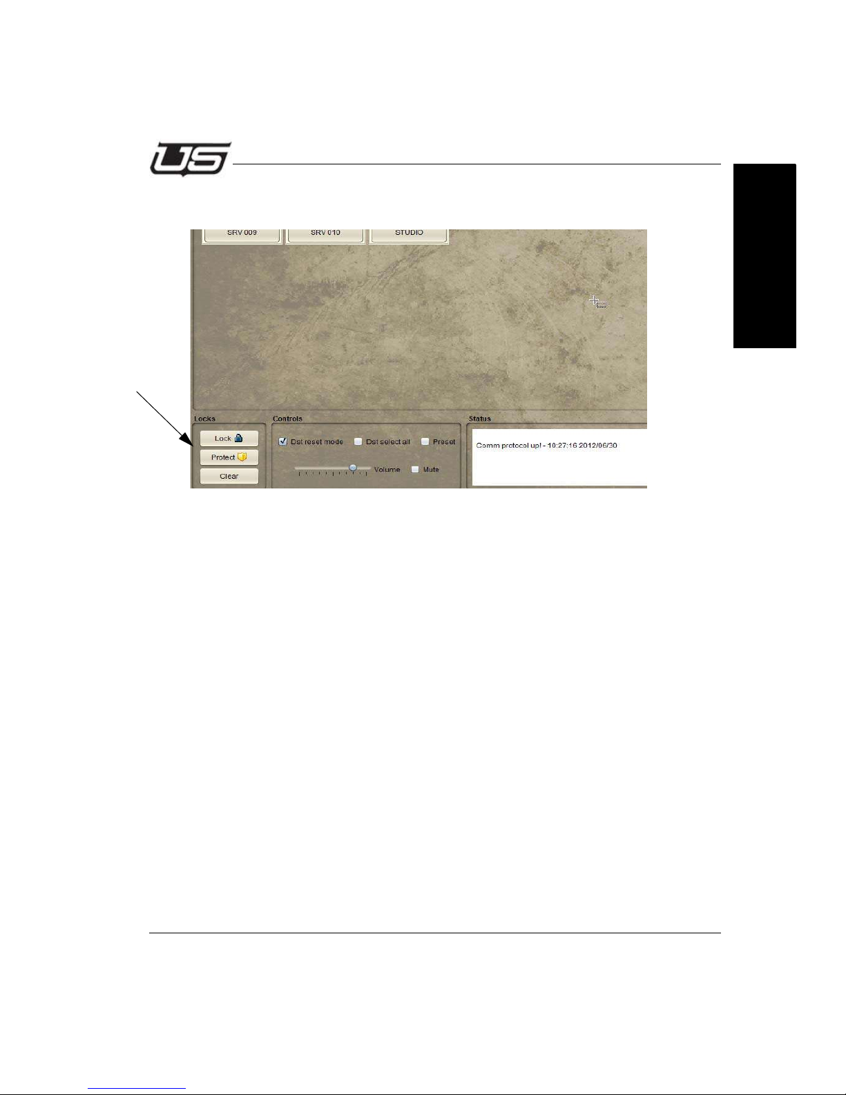
Destinations can be locked or protected by clicking the corresponding buttons within the
lower-left of the display.
Figure 3-35.
Takes can still be made on Destinations in Protect mode locally, while remote users will not
have access to protected Destinations. Locked Destinations are not switchable by anyone
until the lock is actually cleared.
Section 3
The status window (lower right above) will display all Controller activity.
Section 3 3-27
Page 88
The Router Applet
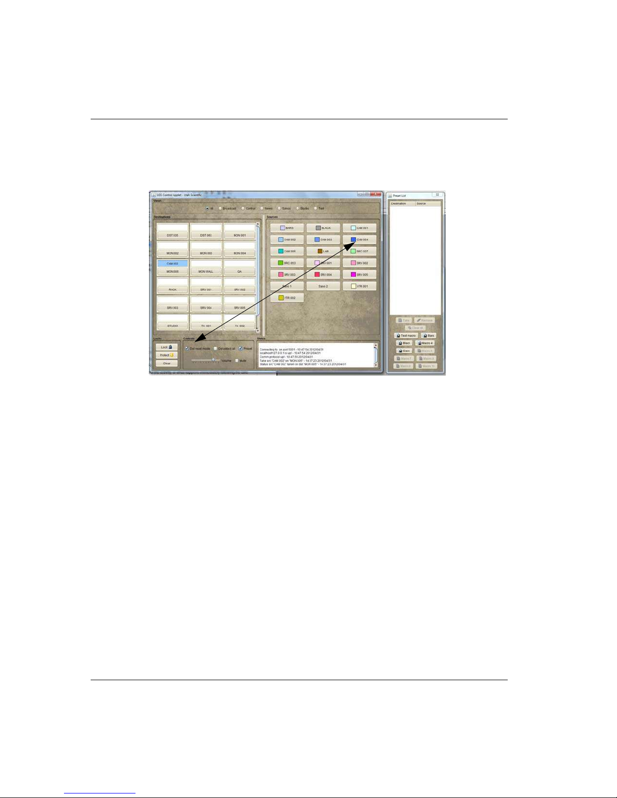
If the Preset box is checked (Controls group area), the ‘Take’ button (lower right)
will blink, waiting for the user to activate the take by a button click.
Preset (checkbox)
Figure 3-36.
The ‘status’ will alternate between what currently exists, and what the action will
be once the Take commences.
Takes will occur immediately if the Preset box is not checked.
When this window is active all actions will be directed to the preset list (right side
list window), rather than immediately affecting the router.
3-28 The Router Applet
Page 89
Router Control
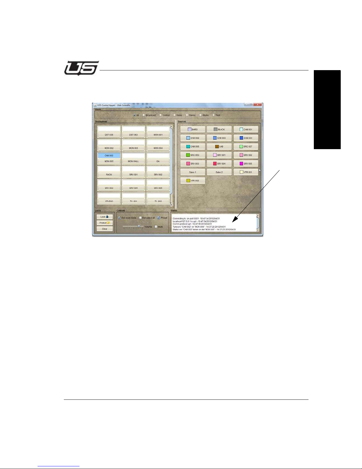
All UDS Control activity is logged in the Status box in the lower right portion of the
display.
Section 3
Figure 3-37.
Section 3 3-29
Page 90
The Router Applet
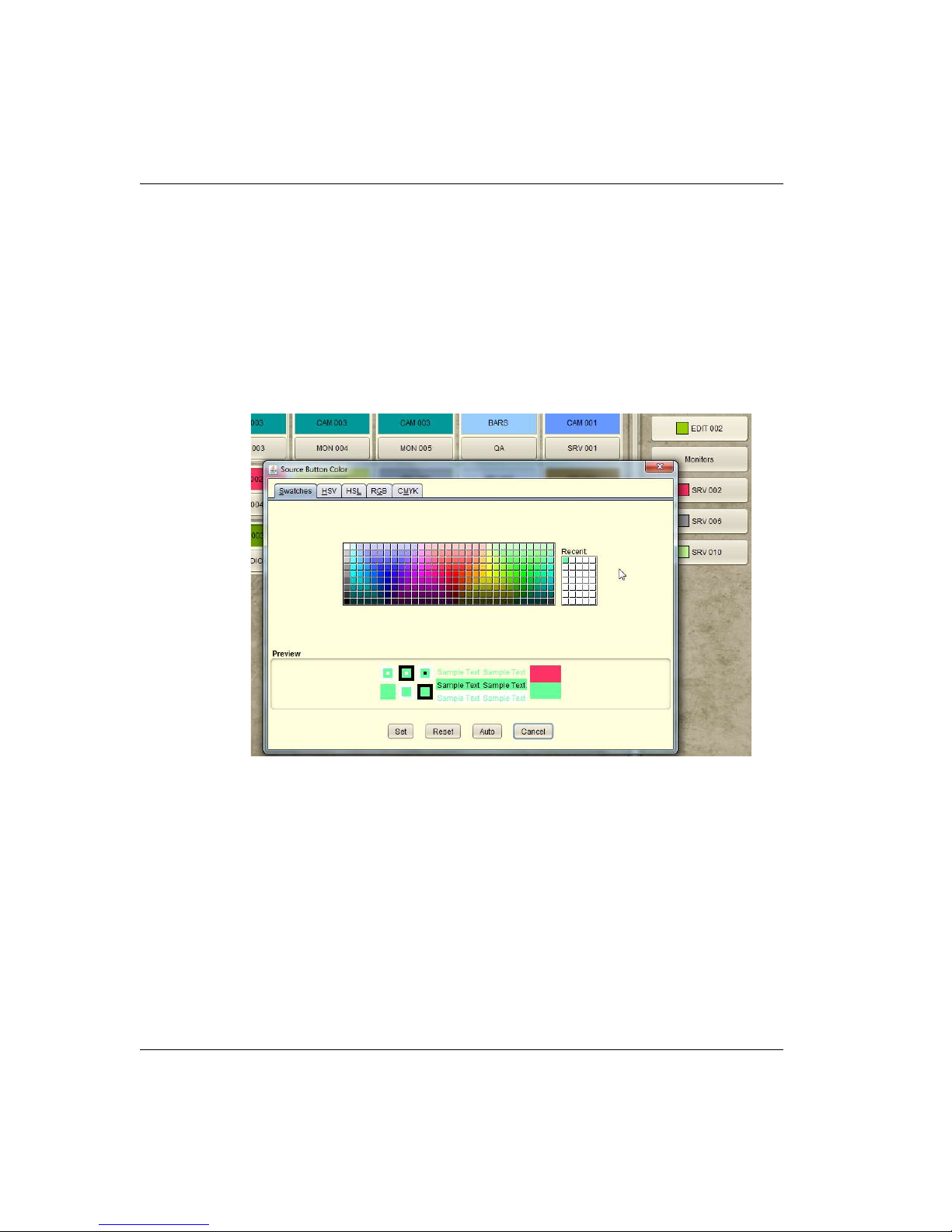
Changing the Button Color Scheme
Changing the Source button color schemes is useful for designating status colors for
different equipment sets. Right-click on a Source button to produce a color picker window.
Use the Auto button to [ask the system to] uniquely color all Source buttons. This is
useful when original button colors are needed quickly. (A prompting dialog will appear
before all buttons are colored.)
Figure 3-38.
Use the Auto button to [ask the system to] uniquely color all Source buttons. This is
useful when original button colors are needed quickly. (A prompting dialog will appear
before all buttons are colored.)
3-30 The Router Applet
Page 91
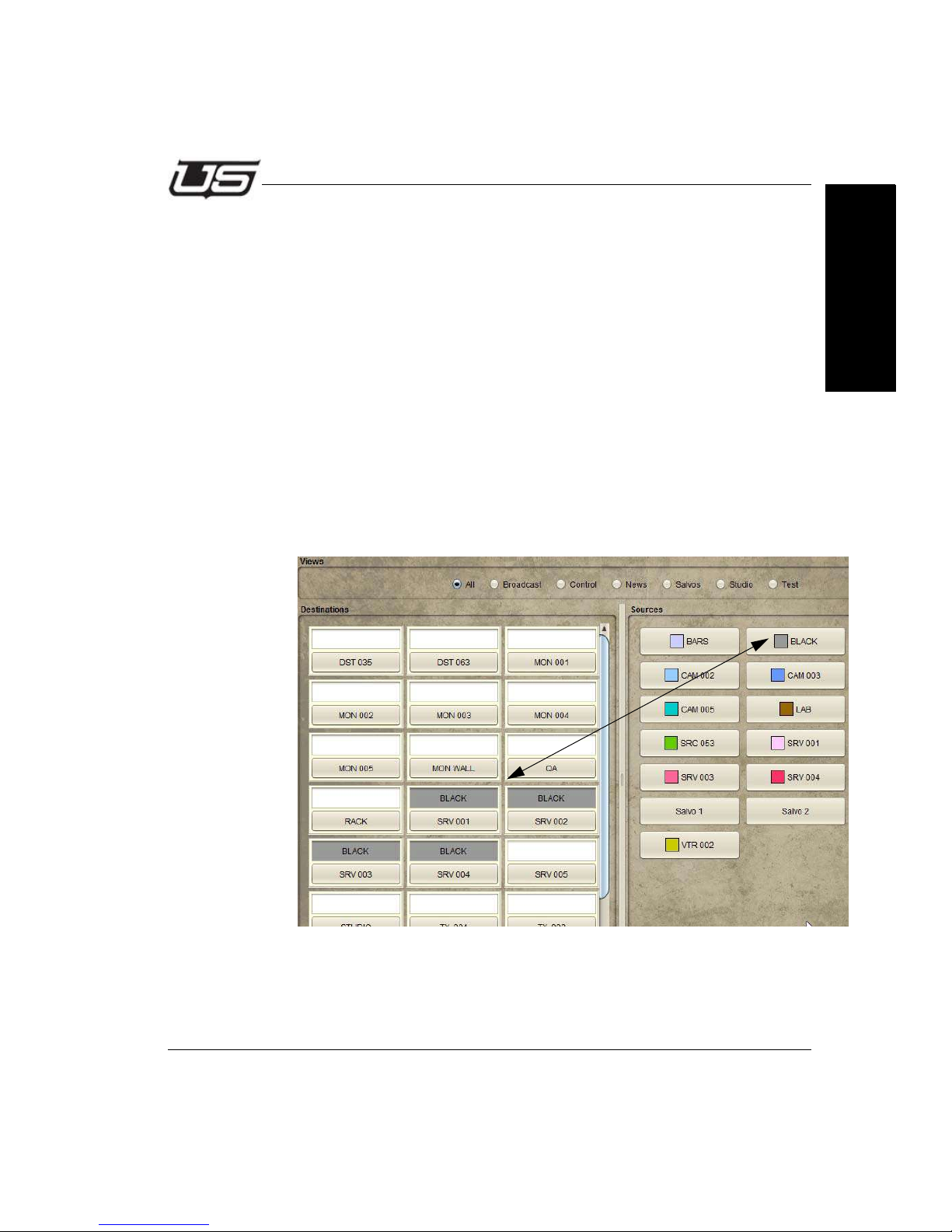
Router Control
Destination Reset Mode (checkbox)
The Destination Reset Mode checkbox (Dst reset mode) will control the
activity, or what happens immediately following the take. Specifically, when
checked, the Destination button itself is no longer selected (or highlighted)
after the Take is made. If not checked, the Destination button will remain
selected after the Take is made. This features allows the user to continually
make new selections and takes on the same button without having to reset
the button each time.
When the box is checked, you will need to select (or highlight) the Destination
on every instance prior to making a new Source indication. When the box is
unchecked you can continually make new Source selections without having
to re-highlight the Destination button (box) each time.
Multiple Destination Selection
You can select (or highlight) multiple Destination buttons, then select a
Source to simultaneously affect all selected destinations.
Section 3
Section 3 3-31
Figure 3-39.
Page 92
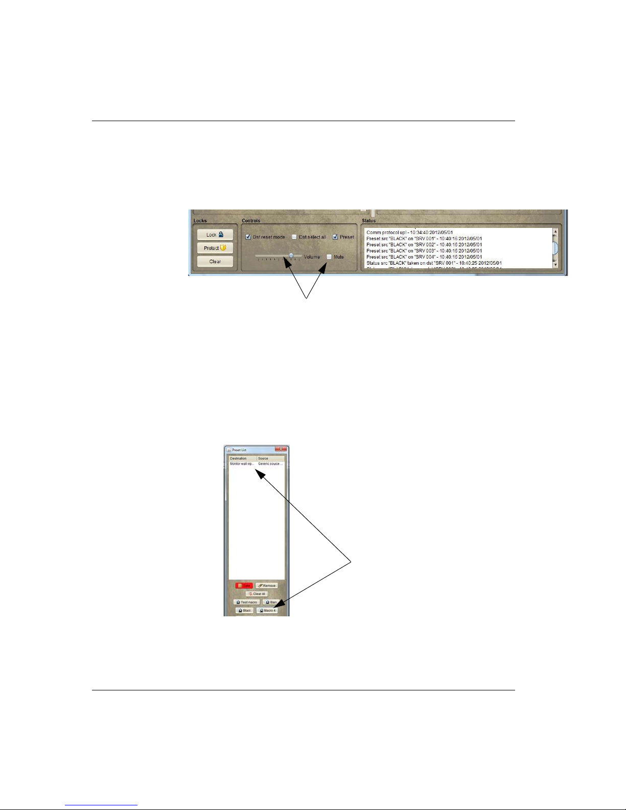
The Router Applet
Audio
Take status is indicated by the audio control at the bottom of the display. If
the Mute box is unchecked, takes are heard and controlled with the
corresponding audio slider bar.
Figure 3-40.
Macro buttons
A series of Takes can be saved as a Macro while in the Preset mode.
Macros work like Salvos, but are saved to the PC where they are
configured and cannot be used system wide. To save a Macro, right click
on the Macro switch and select Save.
The Macro buttons allow you to save the take action prior to the actual
take being made. Macros can be customized by name, or edited as
needed. Macros work on a local basis at each control station.
Figure 3-41.
3-32 The Router Applet
Page 93
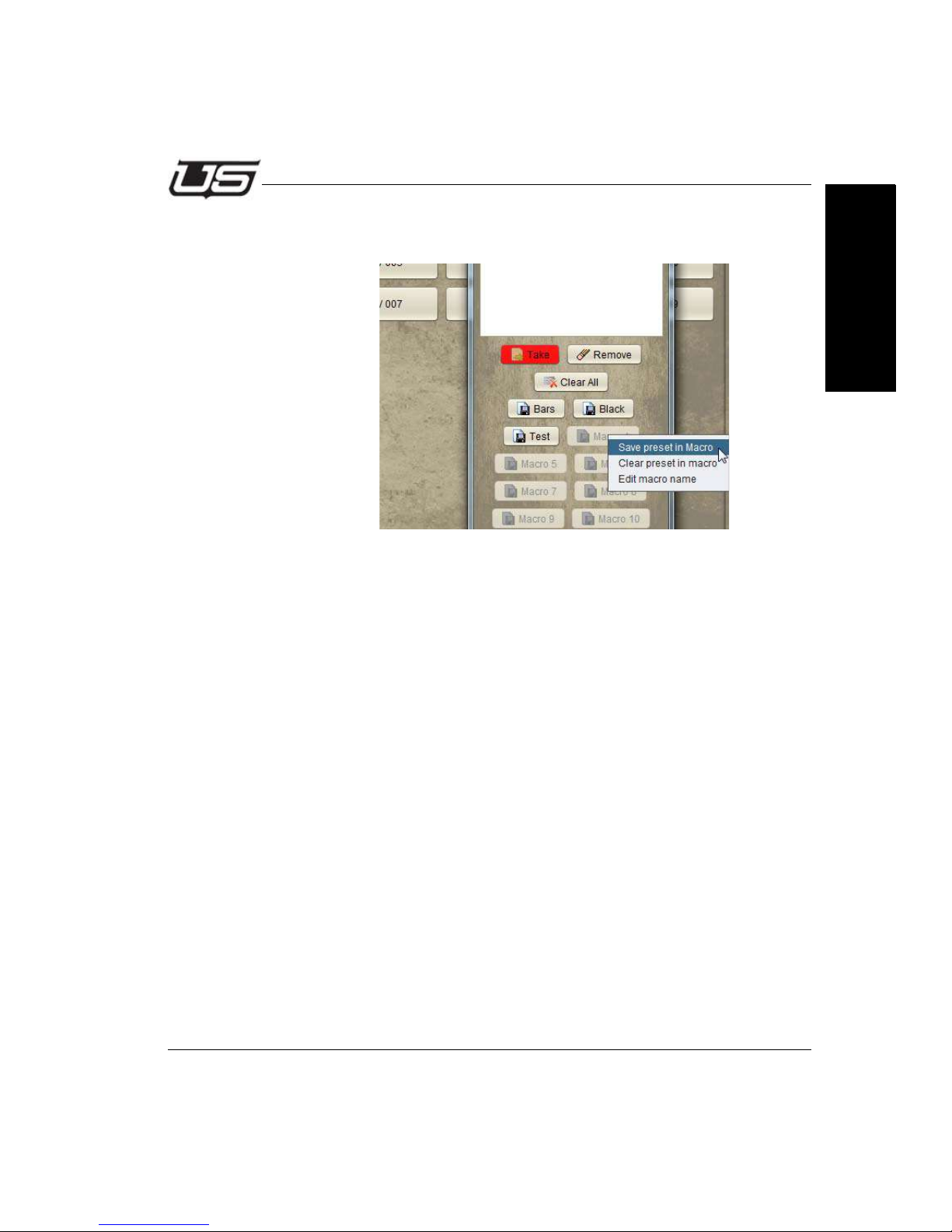
Router Control
Macros are saved in the listing, or renamed by clicking the selection at the
bottom of the pop up window.
Figure 3-42.
Section 3
Section 3 3-33
Page 94
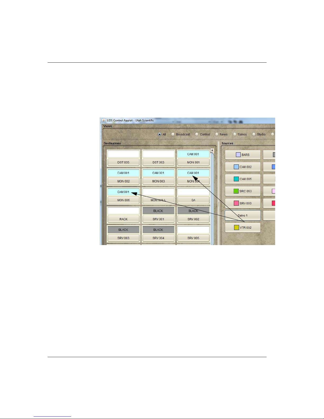
The Router Applet
Salvos
The Salvo buttons inside the Sources group area allow you to activate
Takes on multiple Destinations. As an example, one Salvo button may
control multiple Destinations with pre-configured Sources for each salvo
destination.
Salvos are set up on a system-wide basis with the configuration window.
3-34 The Router Applet
Figure 3-43.
Page 95
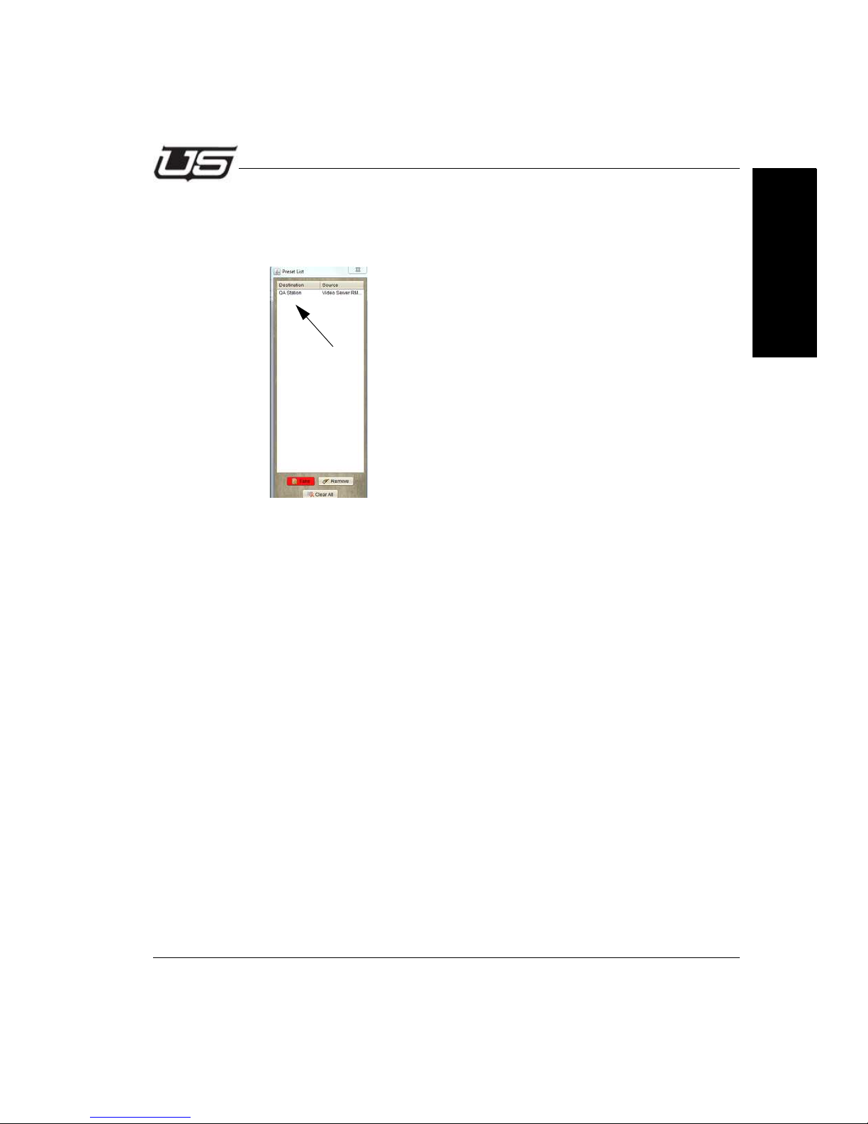
Router Control
Preset List Window
The waiting takes will be listed within the display once a Destination and
Source have been selected.
Figure 3-44.
Please continue on to the next section, Hardware Based Control Panel Configuration
and Operation, for UDS panel setup and maintenance detail.
Section 3
Section 3 3-35
Page 96

The Router Applet
3-36 The Router Applet
Page 97

Introduction
Section 4
The Control Applet
Introduction
As discussed in Section 3, the UTAH-100/UDS can be controlled and monitored using a
virtual control via a built-in web interface, or external hardware control panel via Ethernet.
This section describes the setup, configuration and operation of the optional external
control panel.
Section 4
Section 4 4-1
Page 98
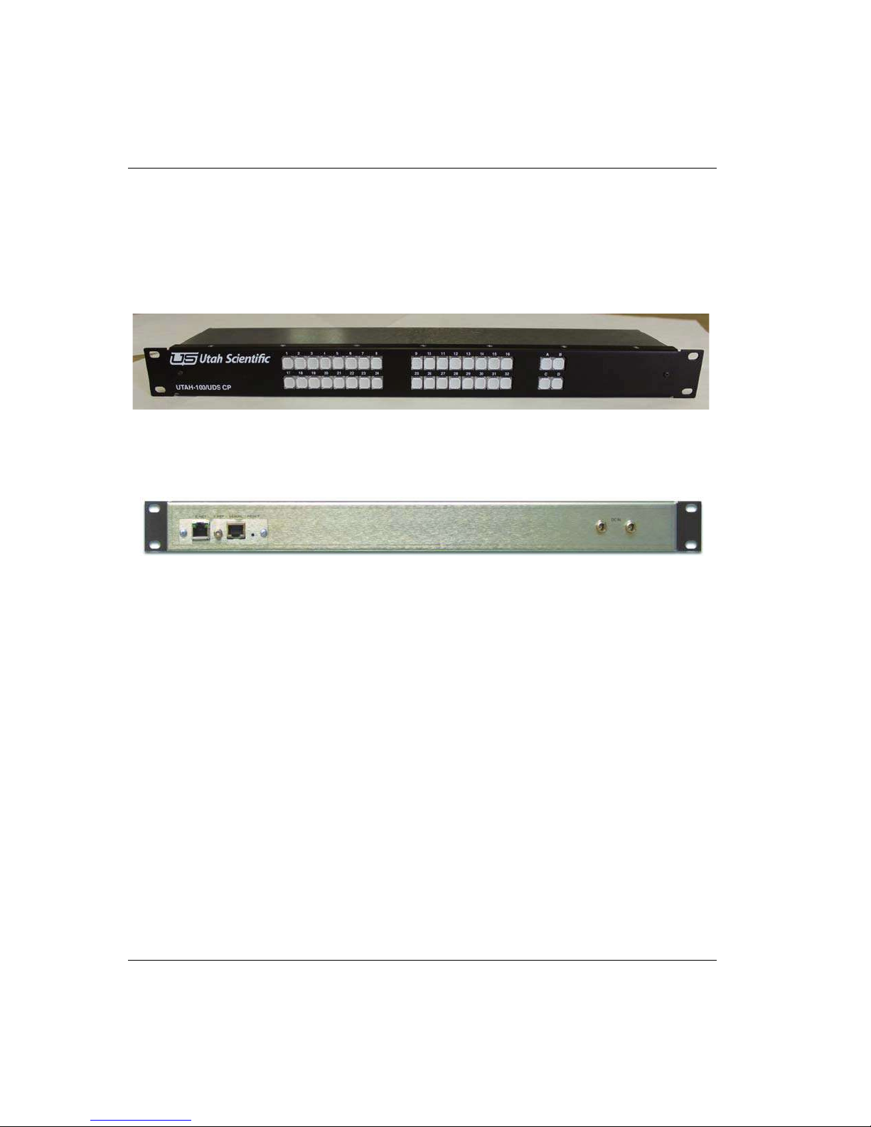
The Control Applet
The UTAH-100/UDS CP
The external hardware control panel and virtual control via Ethernet extends the functionality
of the system to local and remote users as necessary.
Front View
Figure 4-1.
Rear View
Figure 4-2.
Setup
Use the following steps to install the Utah-100/UDS Systems into the rack frames:
1. Determine the vertical layout of your frames before you begin the installation.
2. Once your layout is determined, install the Utah-100/UDS chassis' in the 19" rack
frame.
3. Connect the Ethernet cable for network communications.
4-2 External Control Panel
Page 99
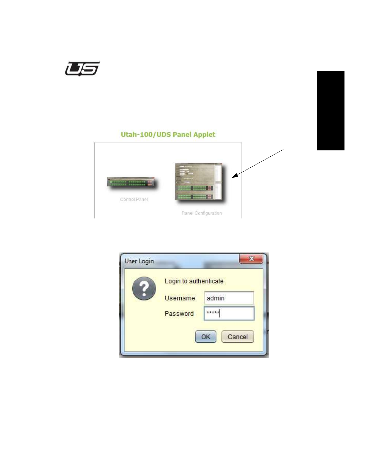
Panel Configuration
Panel Configuration
Panel Configuration is activated by launching a web browser and entering the panel’s IP
address as the URL. The panel must be connected to the network in order to
communicate properly.
Click the Config icon to activate the UDS Panel Config applet.
Figure 4-3.
Enter the default username and password (admin/admin).
Section 4
Figure 4-4.
The following window will appear (next).
Section 4 4-3
Page 100
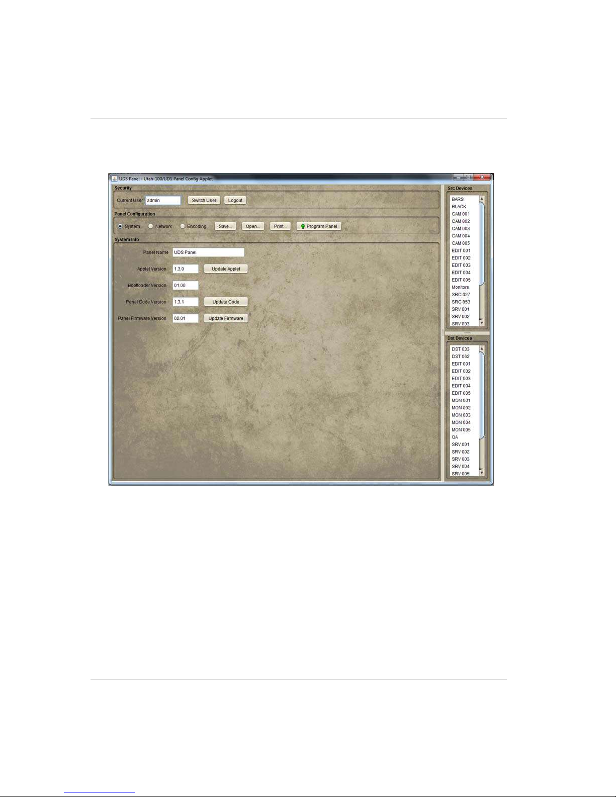
The Control Applet
Use the radio buttons in the Panel Configuration section to navigate through the
configuration screens; System, Network and Encoding.
Figure 4-5.
Save - Saves the current panel configuration to a file on your computer.
Open accesses the directory containing previously saved panel configuration files.
Print allows you to produce a listing of all buttons and assignments when encoding is
complete. Printing will produce the entire list along with a button label reference sheet that
can be helpful for operators.
4-4 External Control Panel
 Loading...