

Page 1

max 30 feet
Add-a-Panel
Option
Add-a-Panel
Option
a.
b.
max 30 feet
Add-a-Panel
Option
Add-a-Panel
Option
a.
a.
b.
Add a Panel Kit
for the All Purpose Ventilator
and Roof Mount Attic Fan Models 9910APV and 9910TRP
Installation and Mounting Guide
Thank you for purchasing the Add-a-Panel option from U.S. Sunlight Corp.
We are committed to providing alternative energy products that can improve your
everyday life and our environment. We have reduced packaging material and
eliminated Styrofoam to reduce the impact on landfills. We offer an installation
video that is available to view online at www.ussunlight.com.
If there is a problem with your U.S. Sunlight product call us at 1-866-446-0966.
Spare parts, installation advice, or recommendations for professional installers
in your area are only a phone call away. Professional installation may be much
less than you expect, please call us to get average rates for your area.
Before beginning the installation of your new All Purpose Ventilator, please read
through the entire installation instructions and call us if you have any questions.
683 Pinnacle Place | Livermore, CA 94550
Tel: 866-446-0966
www.ussunlight.com
support@ussunlight.com
Kit Includes:
Panel with 30 ft
of wire and Y-adapter
1 set of wall brackets
Optional Hardware (not included)
Panel mounting options: (roof mounting)
• 3” galvanized deck screws
(for mounting to composition roof)
• caulk gun with roof tile adhesive
(for mounting solar panel directly to s-tile, at tile or metal roofs)
Panel mounting options: (wall mounting)
• 1.5”- 3” anchor screws (depending on your specic type of
stucco, cement or brick wall. Must support up to 20 lbs)
• 1.5”- 3” galvanized screws (depending on your specic
type of wood or vinyl siding. Must support up to 20 lbs)
• caulk gun with roof tile adhesive
(for sealing screw heads when mounting to wood or vinyl siding)
Mounting the additional
Solar Panel
If you are adding the panel to an All Purpose Ventilator
(gable fan) or a roof mounted fan such as the Solar Powered
Attic Fan or Roof Mount Attic Fan be sure to measure the
distance before installing
Using with gable
mounted attic fan
fig. 1
The Solar panel unit comes with 30 ft. of wire. It is a good idea to measure the distance from the
fan’s motor and where you’ll be installing the panel to make sure you have enough wire to cover the
span. (between a. and b. on fig. 1 & 2)
Using with roof
mounted attic fan
fig. 2
Page 2
Selecting the best location
for the additional panel
We’ve designed the add-a-panel to allow you the flexibility to place it where you can get the best exposure to the sun during the
course of the day. You can place it on the opposite side of the roof or an exterior wall that gets the sun exposure in the morning or
afternoon. Survey your home to determine the best location for the extra panel. If the first panel gets morning sun but no afternoon
sun, install the second panel where it will get exposed more to the afternoon sun and vice-versa. This will keep the fan running for
much longer periods during the day.
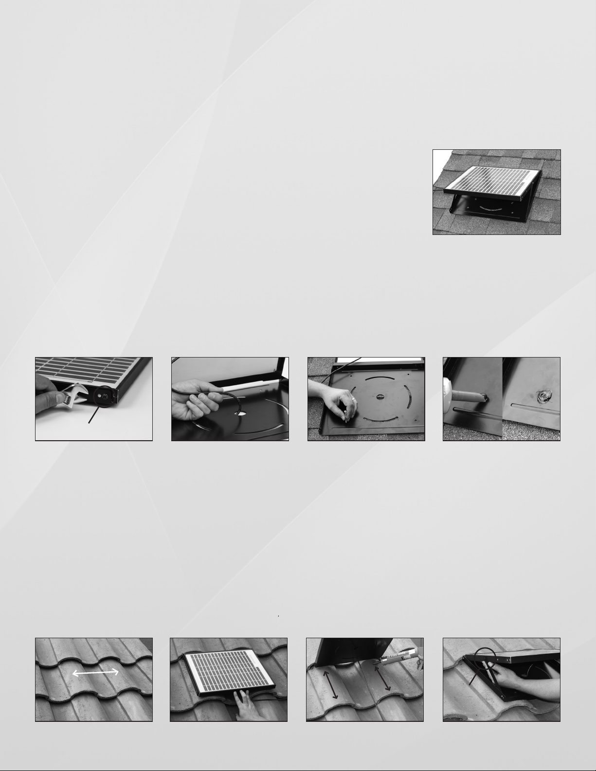
Surface mounting on composition roofs:
Step 1.
Loosen and remove screw A (both sides) to allow the panel to swing away from the base.
Set the screws aside. (fig. 3)
Step 2.
Before mounting, make sure to pull the wire back through the hole in the center of the base so the base can lay flat on the roof surface
when installed. (fig. 4)
Step 3.
Mount the base using four 3” galvanized screws making sure to seal the screw holes with a roof tile adhesive as shown. Tilt the panel
away from the base while installing the screws. If the panel is to remain flat against the base when installed it is recommended that
you allow the roof tile adhesive to completely dry before contacting with the panel. (fig. 5 & 6)
screw A
fig. 3
fig. 4
fig. 5
fig. 6
Surface mounting for S-Tile, Flat Tile or Metal roofs
Step 1.
Determine the location of the contact points by positioning the panel in the desired area. For S-Tile roofs, find a position with as much
surface area coming in contact with the bottom of the panel as possible. The panel must be mounted on at least 2 rows of tile as
shown. (fig. 7 & 8)
Step 2.
Apply enough roof tile adhesive to the underside of the base to firmly secure the panel to the surface. Both surfaces should be dry
and free of any dirt or solvents. (fig. 9)
Step 3.
The panel can be tilted into two positions with the adjustment arm, chose the best angle and reinstall the adjusting screws (screw A). (fig. 10)
mount on at
least 2 tiles
reinstall
screw A
fig. 7 fig. 8
fig. 9 fig. 10
Page 3

Wall mounting:
Brackets are included to mount the panel to a wall if preferred.
First, assemble the braces to the brackets as follows:
Step 1.
Attach the brace to each bracket with the cross brace bolt and nut (E.) (fig. 11)
Step 2.
Attach the brackets to the panel using the 4 bolts (F.) (fig. 12)
Step 3.
Depending on the material your wall is made of, mount the assembly to the wall using appropriate fasteners
(see “Optional Hardware” on page 1 for details). (fig. 13 and 14)
see Optional
bolt F
Hardware on
page 1
fig. 11
fig. 12 fig. 13 fig. 14
Connecting the motor and two panels
with the Y-Adapter
The Y-adapter allows 2 solar panels to be connected in parallel to the motor. This
does not double the voltage to the motor - it simply provides another power source to
allow the unit to operate for a longer period of time during the day.
A. For the 9910APV:
Step A1.
Connect the leads of the first solar panel to the Y-Adapter
as shown in (fig. 15 & 16) Make sure to connect black to
black and red to red, etc.
fig. 15
Step A2.
Connect the leads from the second panel (fig. 16) to the
Y-Adapter in the same fashion. If necessary, use a piece
of electrical tape to cover the black leads so they don’t
touch the red leads when everything is connected.
connect
to the
motor
fig. 17 fig. 18
Step A3.
Connect the other end of the Y-Adapter (fig. 17) to the
motor make sure to connect the black lead to the black
post and red lead to the red post. (fig. 18)
fig. 16
B. For the 9910TRP:
Step B1.
An access point is located under the shroud to allow for
connecting an extra panel. (fig. 19)
Cut the zip ties that hold the wires to the frame. (fig. 20)
fig. 19
Step B2.
Disconnect the panel leads from
the motor leads. (fig. 21)
Step B3.
Now connect the Y-Adapter as
described in steps A1 - A3 to the
motor and panel leads as shown
in (fig. 22)
Step B4.
Bundle and re-attach the wires to
the rodent screen with zip ties.
fig. 20
fig. 21
fig. 22
Page 4

w arranty
cut here
R E G I S T R A T I O N
WE WOULD LOVE TO HEAR FROM YOU!
To register please visit our website: www.ussunlight.com
U.S. Sunlight, Inc. | 683 Pinnacle Place, Livermore, CA 94550
Name ______________________________________ Address ________________________________________________________
City ________________________________________________ State _______ Zip ______________Date of Purchase __________
Purchased From ________________________________________ Name of Installer ____________________________ (self __ )
Phone # of Installer ____________________________ Method of application : Gable _____ Static _____ Crawl space _____
Comments __________________________________________________________________________________________________
____________________________________________________________________________________________________________
____________________________________________________________________________________________________________
____________________________________________________________________________________________________________
or simply fill out this form and mail to:
 Loading...