

Page 1
8912VK Garage Ventilation Kit
Tel: 877-50-USSUN
www.ussunlight.com
Installation and Mounting Guide
Thank you for purchasing a Ventilation Kit from U.S. Sunlight Corp. We are committed to providing alternative energy products
that can improve your everyday life and our environment. We have reduced packaging material and eliminated Styrofoam to
reduce the impact on landlls.
If there is a problem with your U.S. Sunlight product call us at 1-877-50-USSUN
Spare parts, installation advice, or recommendations for professional installers in your area are only a phone call away.
Professional installation may be much less than you expect, please call us to get average rates for your area.
Please note that this product is designed for asphalt shingles. If you have spanish tile, s-tile, concrete, metal or at roof,
please call us before attempting to install the product.
Before beginning the installation of your Ventilation Kit, please read through the entire installation instructions and call us
if you have any questions.
This product requires the additional purchase of a U.S. Sunlight Solar Attic Fan. Call 1-877-50-USSUN to order.
support@ussunlight.com
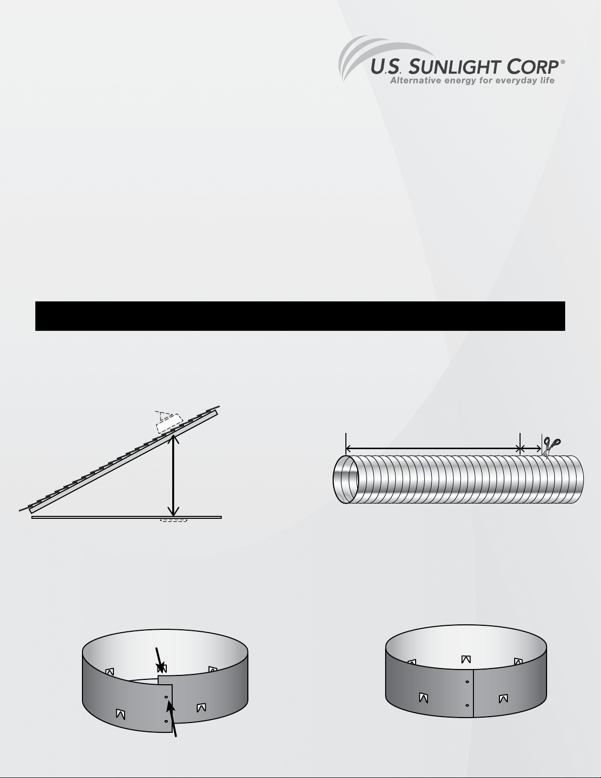
Step 1
Measure the distance between the underside of the roof and the top of the ceiling (g.1). Add 6” to this and cut
the exible tube to length. (g. 2)
height
Fig. 1
Step 2
Rivet the two ends of the collars together to form two separate rings. (g. 3a and 3b)
height
6”
Fig. 2
Fig. 3a
Fig. 3b
© Copyright 2013 US Sunlight Corp, Inc. 8912VK C01 ver 1
Page 2
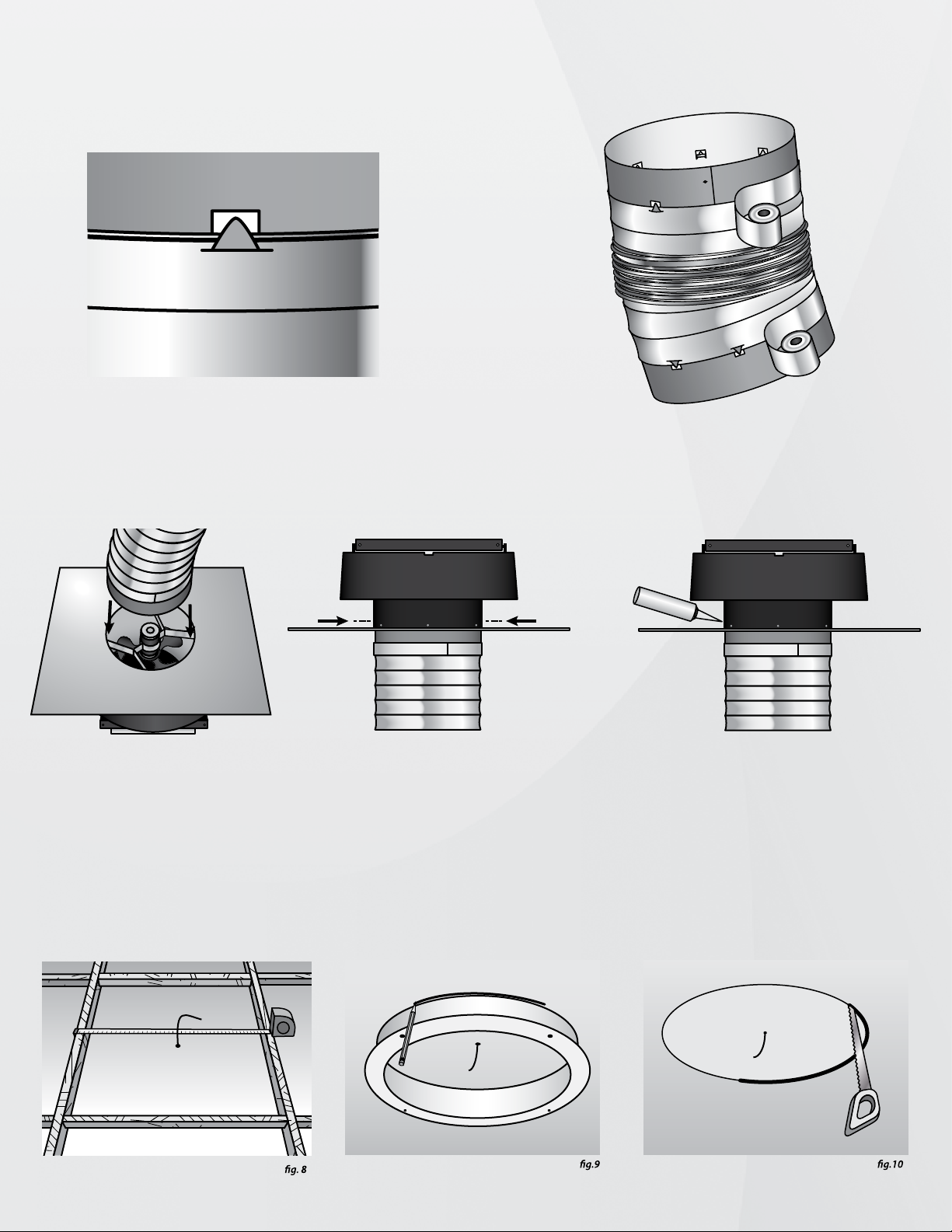
Step 3
Hook the end loop of wire of the exible tube to the notches on the collar (g.4).
Duct tape the exible tube to the two collars (g.5).
Fig. 4
Fig.5
Step 4
From underneath, insert one collar into the tunnel of the solar attic fan (g.6a), and rivet in place (g.6b). From the outside,
seal rivet heads with silicone (g.7).
* Install the U.S. Sunlight Roof Mounted Solar Attic Fan per normal instructions.
Fig. 6a
Fig. 6b
Fig. 7
Step 5
From inside the attic, determine the desired location, center a nail or piece of wire between the ceiling joists and through the
ceiling so it is visible from below (g.8). Use the ceiling frame as a template and draw the hole to be cut (g.9). Begin cutting
the circle with a drywall saw (g.10).
Page 3

Insert the Ceiling Frame and attach with the included 2” Ceiling Frame Screws and plastic lugs. The plastic lugs are placed on
the topside of the ceiling. Fasten the screws through the holes on the ceiling frame, the ceiling and into the white plastic lugs
and tighten (g.11a and 11b).
Plastic Lug
Drywall
Ceiling Frame
Ceiling Frame Screw
Step 6
Position lower collar into ceiling frame (g.12a) and screw in place (g.12b).
Lower
Collar
Drywall
Ceiling Frame
Step 7
Put magnetic diuser in place, magnets connect to ceiling frame screws (g.13).
Extra magnets act as spacers to increase available inlet air ow.
 Loading...