

Page 1
I
N
U
U
S
D
E
T
S
C
O
M
S
N
A
P
S
T
C
Y
O
V
E
T
A
E
T
S
UNITED STATES STOVE COMPANY
227 Industrial Park Road • P.O. Box 151 • South Pittsburg, TN 37380 • (423) 837-2100
Natural Gas Model
VF30IN
VF30I FIREPLACE INSERT
VENT-FREE ROOM HEATER
This is an vent-free gas-fired heater. It uses air
(oxygen) from the room in which it is installed.
Provisions for adequate combustion and ventilation
air must be provided. Refer to "Adequate
Combustion And Ventilation Air" on page 7 of this
manual.
THIS APPLIANCE MAY BE INSTALLED IN
AN AFTERMARKET* MANUFACTURED
(MOBILE) HOME, WHERE NOT
PROHIBITED BY STATE OR LOCAL
CODES.
*Aftermarket: Completion of sale, not
for purpose of resale, from the
manufacturer.
Propane (LPG) Model
VF30IL
G
I
S
N
E
D
C
I
R
A
E
N
M
A
GS
A
A
R
S
N
S
O
I
O
T
C
A
I
C
D
E
E
R
I
T
F
I
WARNINGS
WARNING: If the information in this manual is not
followed exactly, a fire or explosion may result causing
property damage, personal injury or loss of life.
Do not store or use gasoline or other flammable vapors and
liquids in the vicinity of this or any other appliance.
WHAT TO DO IF YOU SMELL GAS
• Do not try to light any appliance.
• Do not touch any electrical switch; do not use any
phone in your building.
• Immediately call your gas supplier from a neighbor's
phone. Follow the gas supplier's instructions.
• If you cannot reach your gas supplier, call the fire
department.
THIS APPLIANCE IS ONLY FOR USE WITH
THE TYPE OF GAS INDICATED ON THE
RATING PLATE. THIS APPLIANCE IS NOT
CONVERTIBLE FOR USE WITH OTHER
GASES.
Installation and service must be performed by a qualified
installer, service agency or the gas supplier.
WARNING: This appliance is for installation only in
a solid-fuel burning fireplace or approved ventless
firebox enclosures.
1
851342A 9/98
Page 2

TABLE OF CONTENTS
IMPORTANT SAFETY INFORMATION.............................................................3-4
PRODUCT FEATURES...........................................................................................4
SPECIFICATIONS......................................................................................................5
CONTENTS...............................................................................................................5
UNIT DIMENSIONS................................................................................................6
MINIMUM AND MAXIMUM SIZE OF FIREPLACE.............................................6
ITEMS REQUIRED FOR INSTALLATION...........................................................7
AIR FOR COMBUSTION AND VENTILATION................................................7-11
CLEARANCES TO COMBUSTIBLES...................................................................11
INSTALLING TOP SURROUND & BRASS TRIM...................................................12
PREPARING FIREPLACE......................................................................................13
GAS CONNECTION.........................................................................................14-15
GAS PRESSURE CHECK......................................................................................15
WIRING BLOWER ASSEMBLY............................................................................16
LOGS AND LOG STOP ASSEMBLY....................................................................17
OPERATING INSTRUCTIONS........................................................................18-19
CLEANING / SERVICING.................................................................................20-21
FLAME APPEARANCE.........................................................................................21
PARTS LIST FOR HEATER ASSEMBLY.......................................................22-23
PARTS LIST FOR BURNER & LOG ASSEMBLY........................................24-25
TROUBLE SHOOTING....................................................................................26-27
Installation and repair must be done by a qualified service person. The appliance should be
inspected before use and at least annually by a professional service person. More frequent
cleaning may be required due to excessive lint from carpeting, bedding material, etc. It is
imperative that control compartments, burners and circulating air passageways of the
NOTICE
appliance be kept clean.
2
Page 3
IMPORTANT SAFETY INFORMATION
INSTALLER: Please leave these instructions with the owner.
OWNER: Please retain these instructions for future reference.
IMPORTANT: Read these instructions carefully before installing or trying to operate this heater.
ANY CHANGE TO THIS HEATER OR ITS CONTROLS CAN BE DANGEROUS. IMPROPER
INSTALLATION OR USE OF THE HEATER CAN CAUSE SERIOUS INJURY OR DEATH
FROM FIRE, BURNS, EXPLOSION OR CARBON MONOXIDE POISONING.
WARNING
CARBON MONOXIDE POISONING: Early signs of carbon monoxide poisoning are similar to the flu
1.
with headaches, dizziness and/or nausea. If you have these signs, obtain fresh air immediately. Have the
heater serviced as it may not be operating properly.
The installation must conform with local codes or, in the absence of local codes, with the National Fuel Gas
2.
Code, ANSI Z223.1.
The VF30IN/VF30IL vent-free gas heater system cannot be installed in a bedroom or bathroom.
3.
Solid-fuels shall not be burned in a fireplace where an unvented room heater is installed.
4.
WARNING: Improper installation, adjustment, alteration, service or maintenance can cause injury or
5.
property damage. Refer to this owner's manual. Installation and service must be performed by a qualified
installer; service agency or the gas supplier.
To prevent malfunction and/or sooting, an vent-free gas heater should be cleaned at least annually by a
6.
professional service person. More frequent cleaning may be required due to excessive lint from carpeting,
etc. It is imperative that control compartments, burners and circulating air passageways be kept clean.
Correct placement of the ceramic fiber logs is necessary to avoid problems with sooting. Sooting can settle
7.
on surfaces outside the heater and cause discoloration. See the appropriate sections of this manual for
instructions.
WARNING: Do not allow fans to blow directly into the fireplace. Avoid any drafts that alter burner flame
8.
patterns. Do not place a blower inside burn area of firebox. Ceiling fans may create drafts that alter burner
flame patterns. Sooting and improper burning will occur.
This is an vent-free gas-fired heater. It uses air (oxygen) from the room in which it is installed. Provisions
9.
for adequate combustion and ventilation air must be provided. Refer to installation guidelines.
10.
11.
12.
Children and adults should be alerted to the hazard of high surface temperature and should stay away to avoid
burns or clothing ignition.
Young children should be carefully supervised when they are in the same room with the appliance.
Do not place clothing or other flammable material near the appliance.
3
Page 4
IMPORTANT SAFETY INFORMATION
13.
14.
15.
16.
17.
18.
19.
Outside air ducts in the fireplace shall be permanently closed at the time of appliance installation.
Keep appliance area clear and free from combustible materials, gasoline and other flammable vapors and
liquids.
Fireplace screen must be closed during operation of the heater.
This vent-free gas heater is intended to be smokeless. If logs appear to smoke, turn off the heater and call
a qualified service person. Initial burn off may cause slight smoke and odor during the first four hours of
operation.
Input ratings are shown in BTU per hour and are for elevations up to 2,000 feet. For elevations above 2,000
feet, input ratings should be reduced 4 percent for each 1,000 feet above sea level. Refer to the National Fuel
Gas Code.
The heater and its individual shut off valve must be disconnected from the gas supply piping system during
any pressure testing of that system at test pressures in excess of 1/2 psig (3.5 kPa).
The heater must be isolated from the gas supply piping system by closing its individual manual shutoff valve
during any pressure testing of the gas supply piping system at test pressures equal to or less than 1/2 psig
(3.5 kPa).
20.
Do not use this room heater if any part has been under water. Immediately call a qualified service technician
to inspect the room heater and to replace any part of the control system and any gas control which has been
under water.
PRODUCT FEATURES
Features:
• Heating Efficiency - 99.9%
• Wide BTU Range: 16,000 - 30,000.
• Safe Operation Oxygen Depletion Sensor (ODS).
• Thermostatic Condole
• Fibre Ceramic Logs.
• Push-Button Piezo Ignitor.
• Clean Operation.
• Easy Operation.
• Heats up to 1,000 square feet.
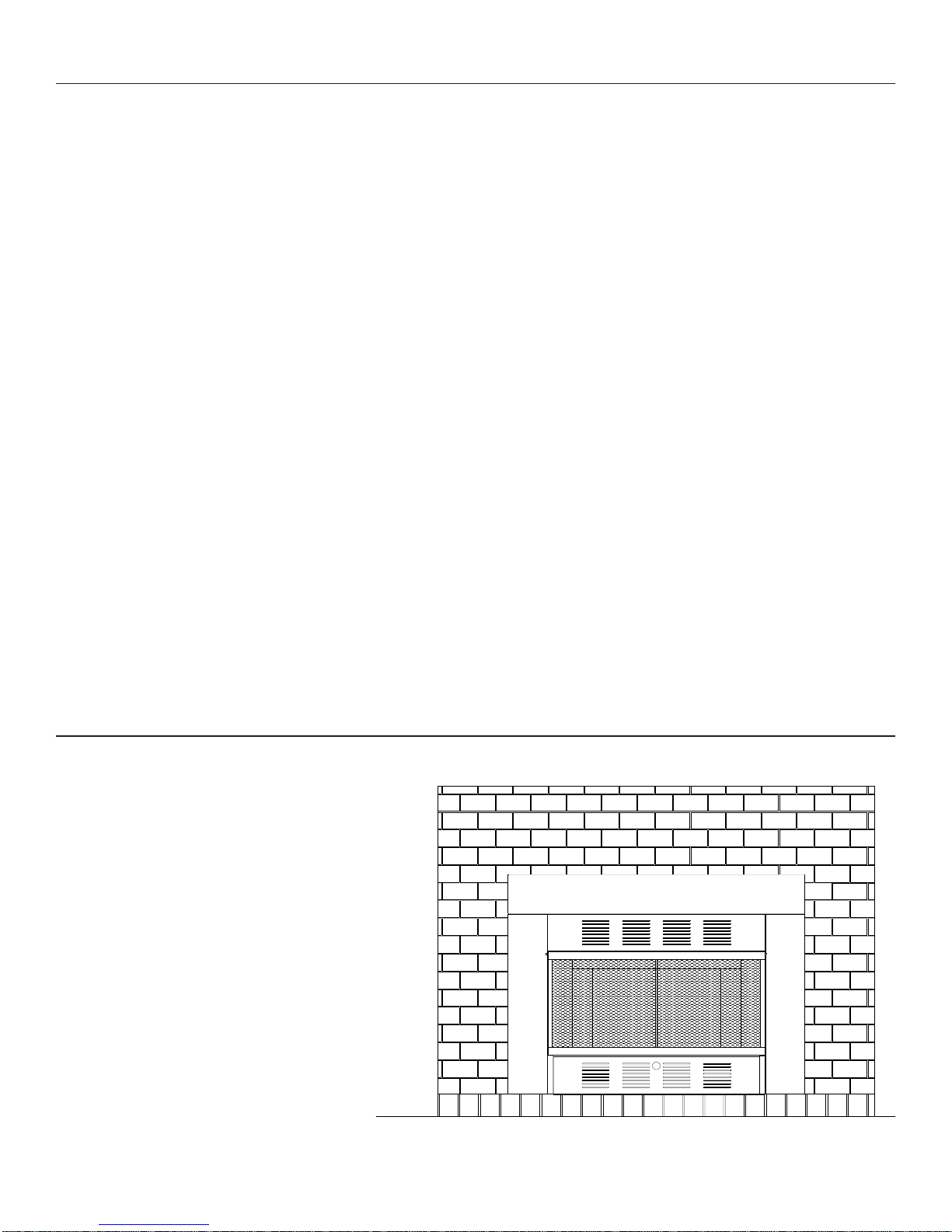
VF30I Vent-free Gas Fireplace Insert
4
Page 5

SPECIFICATIONS
Natural Gas
Manifold Pressure Setting 4" w.c.
Gas Inlet Pressure Maximum 10-1/2" w.c.
Minimum 5" w.c.
Gas Rate
Model Number Type Max BTU/Hr Min BTU/Hr of Burners
VF30IN Manual 30,000 16,000 1
Propane / LPG
Note: An external regulator is required to reduce supply pressure to a maximum of 13" w.c.
Manifold Pressure Setting 10" w.c.
Gas Inlet Pressure Maximum 13" w.c.
Minimum 11" w.c.
Number
Gas Rate
Model Number Type Max BTU/Hr Min BTU/Hr of Burners
VF30IL Manual 30,000 16,000 1
Controls - Main control has 4 positions:
1. OFF - All gas to the gas logs is shut off at the control
2. IGN - Piezo ignitor allows ignition of the pilot without the use of matches or batteries
3. PILOT - Valve position to light / maintain a standing pilot
4. ON - Gas flow to complete system, front burner ignition
Burner Control Knob - Infinite control, rotate clockwise to minimum rate and counterclockwise for maximum
rate. Adjust the control knob between Minimum and Maximum to gain the desired room temperature. The control
will automatically cycle the heater on and off to maintain the desired heat in the room. There are no exacts with
the adjustment, you will need to experiment with the setting to find what works best for you needs.
Number
CONTENTS
VF30IN and VF30IL Vent-free Gas Room Heaters
1. Owner's manual.
2. Log box containing four (4) fiber ceramic logs, refer to installation instructions.
3. Vent-free gas heater.
CHECK THAT ALL LISTED PARTS HAVE BEEN RECEIVED
GLOVES ARE RECOMMENDED WHEN HANDLING CERAMIC FIBER LOGS
TO PREVENT SKIN IRRITATION FROM LOOSE FIBERS. LOGS ARE FRAGILE,
HANDLE WITH CARE.
CAUTION
Carefully inspect the contents for shipping damage and immediately inform your dealer if any damage is found.
5
Page 6
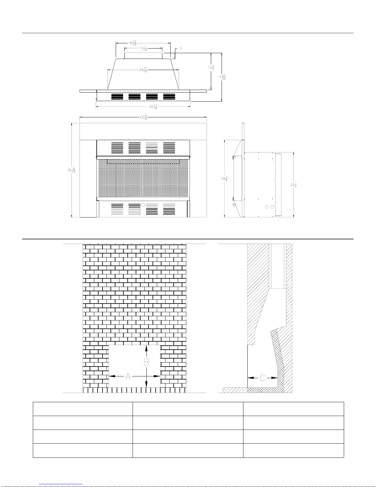
UNIT DIMENSIONS
MINIMUM AND MAXIMUM SIZE OF FIREPLACE
DIMENSION MINIMUM MAXIMUM
A 26" 44"
B 22-1/4" 32"
C 13-1/4" 24"
6
Page 7

ITEMS REQUIRED FOR INSTALLATION
ITEMS REQUIRED FOR INSTALLATION
Ensure that the following items are available before proceeding with installation:
• External regulator (for propane/LPG only) • Manual shutoff valve
• Piping which complies with local codes • Sediment trap
• Pipe sealant approved for use with • Pipe wrench
propane/LPG (resistant to sulfur compounds)
CODES
Adhere to all local codes or in their absence, the latest edition of THE NATIONAL FUEL GAS CODE ANSI Z223.1
or NFPA54 which can be obtained from:
American National Standards Institute, Inc. National Fire Protection Association, Inc.
1430 Broadway or Batterymarch Park
New York, NY 10018 Quincy, MA 02269
Due to high temperatures, do not install the heater:
• Where curtains, furniture, clothing or other flammable objects are less than 60"
from the front of the heater.
• In high traffic areas.
• In windy or drafty areas.
WARNING
DO NOT PLACE CLOTHING OR OTHER FLAMMABLE MATERIAL ON
OR NEAR THE APPLIANCE.
AIR FOR COMBUSTION AND VENTILATION
WARNING
This fireplace shall not be installed in a confined space unless provisions are
provided for adequate combustion and ventilation air. Read the following
instructions to insure proper fresh air for this and other fuel-burning appliances in
your home.
Today's homes are built more energy efficient than ever. New materials, increased insulation, and new construction methods help reduce heat loss in homes. Home owners weather
strip and caulk around windows and doors to keep the cold air out and the warm air in. During
heating months, home owners want their homes as airtight as possible.
While it is good to make your home energy efficient, your home needs to breathe. Fresh air
must enter your home. All fuel-burning appliances need fresh air for proper combustion and
ventilation.
Exhaust fans, fireboxes, clothes dryers, and fuel-burning appliances draw air from the house
to operate. You must provide adequate fresh air for these appliances. This will insure proper
venting of vented fuel-burning appliances.
7
Page 8

AIR FOR COMBUSTION AND VENTILATION
Providing adequate ventilation
The following is excerpts from National Fuel Gas Code. NFPA 54/ANSI Z223.1, Section 5.3,
Air for Combustion and Ventilation.
All spaces in homes fall into one of the three following ventilation classifications:
1. Unusually Tight Construction; 2. Unconfined Space; 3. Confined Space.
The information on pages 7 through 11 will help you classify your space and provide adequate ventilation.
Unusually Tight Construction
The air that leaks around doors and windows may provide enough fresh air for combustion
and ventilation. However, in buildings of unusually tight construction, you must provide
additional fresh air.
Unusually tight construction is defined as construction where:
a. Walls and ceilings exposed to the outside atmosphere have a continuous
water vapor retarder with a rating of one perm (6x10
with openings gasketed or sealed and
b. Weather stripping has been added on openable windows and doors and
c. Caulking or sealants are applied to areas such as joints around window and
door frames, between sole plates and floors, between wall-ceiling joints,
between wall panels, at penetrations for plumbing, electrical, and gas lines,
and at other openings.
-11
per pa-sec-m2) or less
If your home meets all of the three criteria above, you must provide additional fresh air. See
Ventilation Air From Outdoors, page 11.
If your home does not meet all of the three criteria above, proceed to page 9.
Confined Space and Unconfined Space
The National Fuel Gas Code (ANSI Z223.1, 1992 Section 5.3) defines a confined space as a
space whose volume is less than 50 cubic feet per 1,000 BTU per hour (4.8m3 per kw) of the
aggregate input rating of all appliances installed in that space and an unconfined space as a
space whose volume is not less than 50 cubic feet per 1,000 BTU per hour (4.8m3 per kw) of
the aggregate input rating of all appliances installed in that space. Rooms communicating
directly with the space in which the appliances are installed*, through openings not furnished
with doors, are considered a part of the unconfined space.
* Adjoining rooms are communicating only if there are doorless passageways or ventilation
grills between them.
8
Page 9

AIR FOR COMBUSTION AND VENTILATION
Determining if You Have a Confined or Unconfined Space
Use this worksheet to determine if you have a confined or unconfined space.
Space: Includes the room in which you will install the firebox plus any adjoining rooms with
doorless passageways or ventilation grills between the rooms.
1. Determine the volume of the space (length x width x height).
Length x Width x Height = _______________ cu. Ft. (volume of space)
Example: Space size 22 ft. (length) x 18 ft. (width) x 8 ft. (ceiling height) =
3168 cu. Ft. (volume of space)
If additional ventilation to adjoining room is supplied with grills or openings, add the
volume of these rooms to the total volume of the space.
2. Divide the space volume by 50 cubic feet to determine the maximum BTU/Hr the space
can support.
_________ (volume of space) 50 cu. Ft. = (Maximum BTU/Hr the space can support)
Example: 3168 cu. Ft. (volume of space) 50 cu. Ft. = 63.3 or 63,300 (maximum
BTU/Hr the space can support)
3. Add the BTU/Hr of all fuel-burning appliances in the space.
Vent-free Firebox __________________ BTU/Hr
Gas water heater* __________________ BTU/Hr
Gas furnace __________________ BTU/Hr
Vented gas heater __________________ BTU/Hr
Gas firebox logs __________________ BTU/Hr
Other gas appliances* + __________________ BTU/Hr
Total = __________________ BTU/Hr
Example: Gas water Heater 40,000 BTU/Hr
Vent-free firebox with log heater + 39,000 BTU/Hr
Total = 79,000 BTU/Hr
* Do not include direct-vent gas appliances. Direct-vent draws combustion air from
the outdoors and vents to the outdoors.
4. Compare the maximum BTU/Hr the space can support with the actual amount of
BTU/ Hr used.
______________ BTU/Hr (maximum the space can support)
______________ BTU/Hr (actual amount of BTU/Hr used)
Example: 63,300 BTU/Hr (maximum the space can support)
79,000 BTU/Hr (actual amount of BTU/Hr used)
The space in the above example is a confined space because the actual BTU/Hr used is
more than the maximum BTU/Hr the space can support. You must provide additional fresh
air.
Your options are as follows:
A. Rework worksheet, adding the space of an adjoining room. If the extra space provides
an unconfined space, remove door to adjoining room or add ventilation grills between
rooms. See Ventilation Air From Inside Building, page 10.
9
Page 10
AIR FOR COMBUSTION AND VENTILATION
B. Vent room directly to the outdoors. See Ventilation Air from Outdoors, page 11.
C. Install a lower BTU/Hr firebox, if lower BTU/Hr size makes room unconfined.
If the actual BTU/Hr used is less than the maximum BTU/Hr the space can support, the space
is an unconfined space. You will need no additional fresh air ventilation.
WARNING
If the area in which the firebox and gas log heater may be operated is smaller than
that defined as an unconfined space, provide adequate combustion and
ventilation air by one of the methods described in the National Fuel Gas Code,
ANSI Z223.1, 1992, Section 5.3.
VENTILATION AIR
Ventilation Air From Inside Building
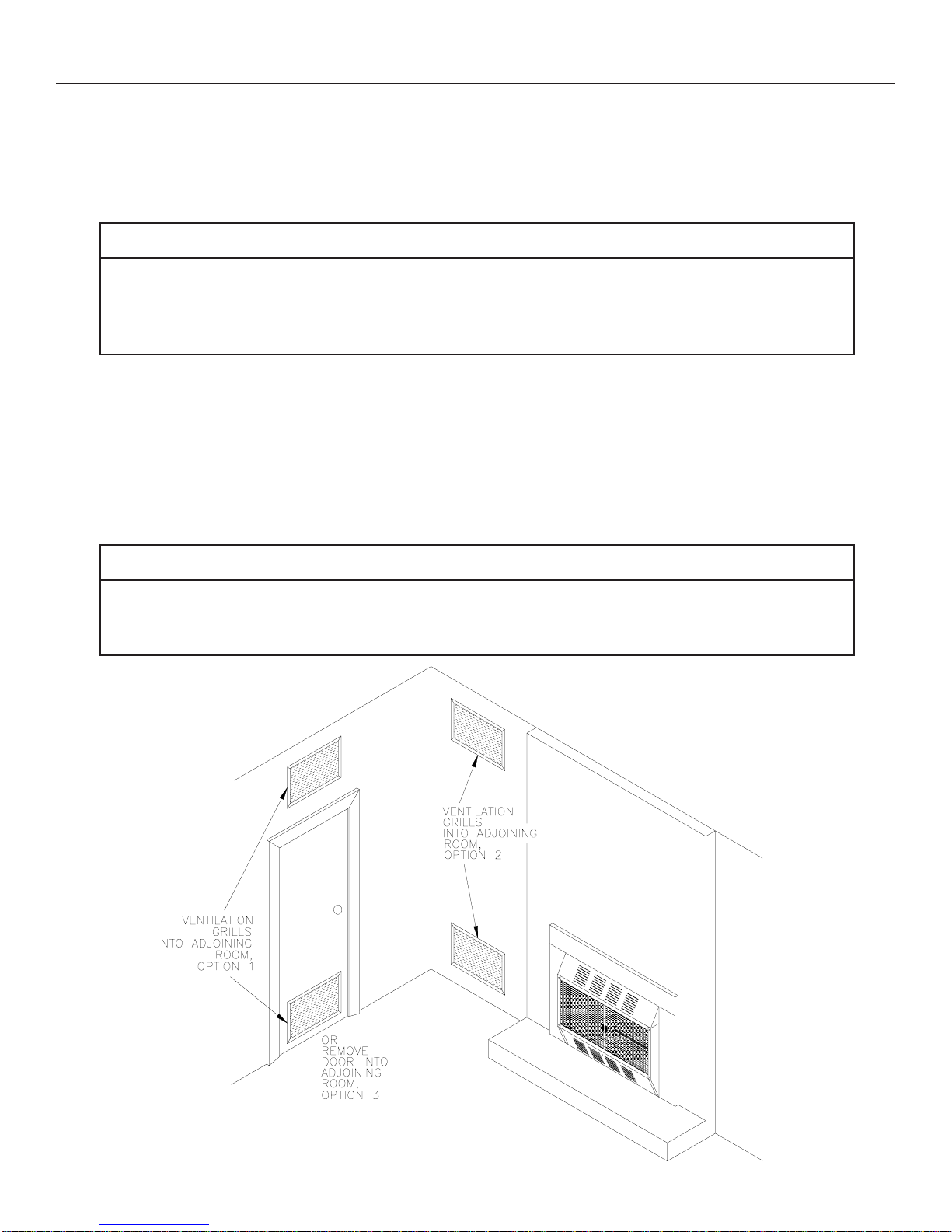
This fresh air would come from an adjoining unconfined space. When ventilating to an adjoining unconfined space, you must provide two permanent openings: one within 12" of the
ceiling and one within 12" of the floor into adjoining room ( see options in Figure 1).
Follow the National Fuel Gas Code NFPA 54/ ANSI Z223.1, Section 5.3, Air for Combustion
and Ventilation for required size of ventilation grills or ducts.
WARNING
Rework worksheet, adding the space of the adjoining unconfined space. The
combined spaces must have enough fresh air to supply all appliances in both
spaces.
FIGURE 1. Ventilation Air from Inside Building
10
Page 11
AIR FOR COMBUSTION AND VENTILATION
Ventilation Air From Outdoors
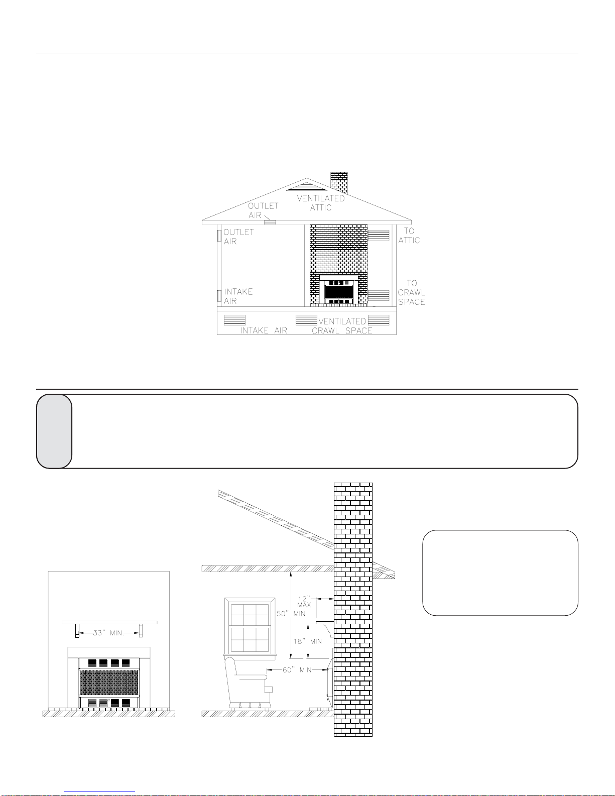
Provide extra fresh air by using ventilation grills or ducts. You must provide two permanent
openings: one within 12" of the ceiling and one within 12" of the floor. Connect these items
directly to the outdoors or spaces open to the outdoors. These spaces include attics and
crawl spaces. (See Figure 2)
IMPORTANT: Do not provide openings for inlet or outlet air into attic if attic has a thermostatcontrolled power vent. Heated air entering the attic will activate the power vent.
Ensure the minimum clearances shown in FIGURE 3 are maintained for
accessibility for purposes of servicing and proper operation.
WARNING
FIGURE 2. Ventilation Air from Outdoors
CLEARANCES TO COMBUSTIBLES
Maintain these clearances to
ensure adequate space
around air opening for
proper operation.
FIGURE 3. Minimum Clearances
Minimum clearances to combustibles:
Sides of heater...........................8" MIN
Front of heater.........................60" MIN
Top of heater............................50" MIN
Top to Mantel...........................18" MIN
11
Page 12
INSTALLING TOP SURROUND & BRASS TRIM
INSTALLING TOP SURROUND
OTE: YOU WILL NEED A FLATHEAD SCREW-
N
DRIVER AND A 3/8" NUT-DRIVER TO ATTACH THE
SURROUND
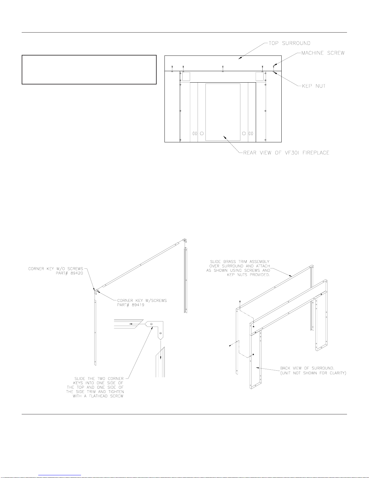
The top surround is shipped unassembled for
shipping purposes only. To install the top
surround place the surround on top of the unit
and line up the holes. Attach the top surround
to the heater using (5) of the machine screws
and kep nuts provided in the parts bag and
tighten firmly.
INSTALLING BRASS TRIM
Before attaching the brass trim to the surround you must first assemble the (3) brass trim pieces
together. Do this you will use the (2) blank corner keys and the (2) corner keys w/screws.
Place one each of the keys together for each side and slide them into the back grooves of the trim as
shown below. Tighten the set screws with a flathead screw driver. (Do this for both sides)
Now slide the Brass Trim Assembly over the surround and attach using the (9) remaining screws and
kep nuts provided in the parts bag.
AND BRASS TRIM.
BRASS KNOB INSTALLATION
For shipping purposes the brass knob on the lower access door comes mounted inside the door. Simply unscrew
the knob using a screwdriver, turn the knob around to the outside and reattach.
12
Page 13
PREPARING FIREPLACE
WARNING: IF THIS APPLIANCE IS INSTALLED IN A FACTORY-BUILT FIREPLACE, DO
NOT BLOCK OR RESTRICT ANY OF THE GRILLES ON THE FACTORY-BUILT FIREPLACE.
THE GRILLES ALLOW AIR CIRCULATION WHICH PREVENTS THE FACTORY-BUILT
FIREPLACE FROM OVERHEATING. BLOCKING OR RESTRICTING THE AIR CIRCULATION
CAN CAUSE A FIRE HAZARD.
WARNING: BEFORE INSTALLING IN A SOLID FUEL FIREPLACE, THE CHIMNEY FLUE
AND FIREBOX MUST BE CLEANED OF SOOT, CREOSOTE, ASHES AND LOOSE PAINT BY
A QUALIFIED CHIMNEY CLEANER.
WARNING: DO NOT US A BLOWER INSERT, HEAT EXCHANGER INSERT OR OTHER
ACCESSORIES NOT APPROVED FOR USE WITH THIS HEATER.
IMPORTANT:
THIS HEATER IS TO BE INSTALLED ONLY IN A NONCOMBUSTIBLE FIREPLACE SUITABLE
FOR BURNING SOLID FUELS (WOOD OR COAL).
ANY OUTSIDE AIR DUCTS AND/OR ASH DUMPS IN THE FIREPLACE SHALL BE
PERMANENTLY CLOSED AT THE TIME OF APPLIANCE INSTALLATION.
Preparing Fireplace:
1. Carefully check the fireplace to be sure
it is large enough and constructed within
the guidelines given in the "MINIMUM
AND MAXIMUM SIZE OF FIREPLACE"
section of this manual.
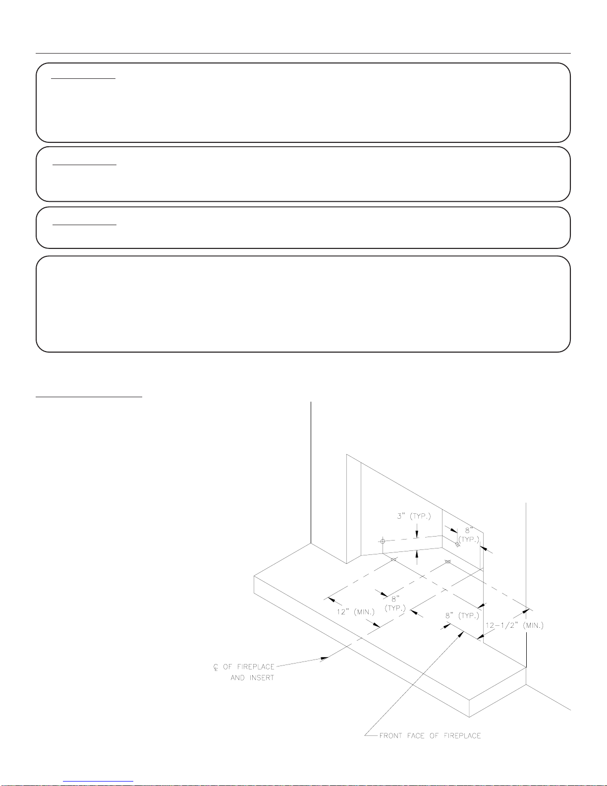
2. You must prepare the fireplace by
cutting holes in the fireplace walls and/or
base to run the gas inlet pipe into the heater.
Below are basic guidelines for positioning
the gas inlet pipe into the fireplace opening.
See the following pages for instructions on
connecting the gas inlet pipe to the heater.
3. Once you have prepared the fireplace
for the heater, you will be able to slide the
heater into the fireplace opening and
complete the gas inlet pipe connection
inside the heater. Do not run piping into
the fireplace until the heater is positioned.
13
Page 14
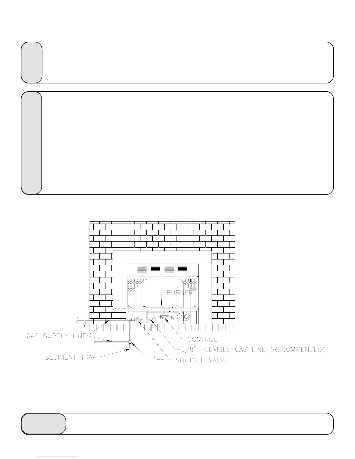
GAS CONNECTION
A qualified gas appliance installer must connect the fireplace to the gas supply.
Consult all local codes.
NOTICE
Use new black iron or steel pipe only. Internally tinned copper tubing can be used in some areas
when permitted by local codes. Only use pipe of 1/2" or greater diameter to allow full gas
volume to heater. Excessive pressure loss will occur if the pipe is too small.
A manual shutoff valve, union and plugged 1/8" NPT pressure tapping point must be installed
upstream of the heater (FIGURE 4).
CAUTION
A sediment trap must be installed upstream of the heater to prevent moisture and contaminants
from passing through the pipe to the heater controls and burners. Failure to do so could
prevent the heater from operating reliably (FIGURE 4).
IMPORTANT: Loosen the pipe adapter on the flex tube before installing to the system piping.
FIGURE 4. Option #1 for gas connection
CHECK GAS TYPE: The gas supply must be the same as stated on heater's rating plate. If the gas supply is
different, DO NOT INSTALL the heater. Contact your dealer for the correct model.
Connecting directly to an unregulated propane/LPG tank can cause an
WARNING
explosion.
14
Page 15
GAS CONNECTION
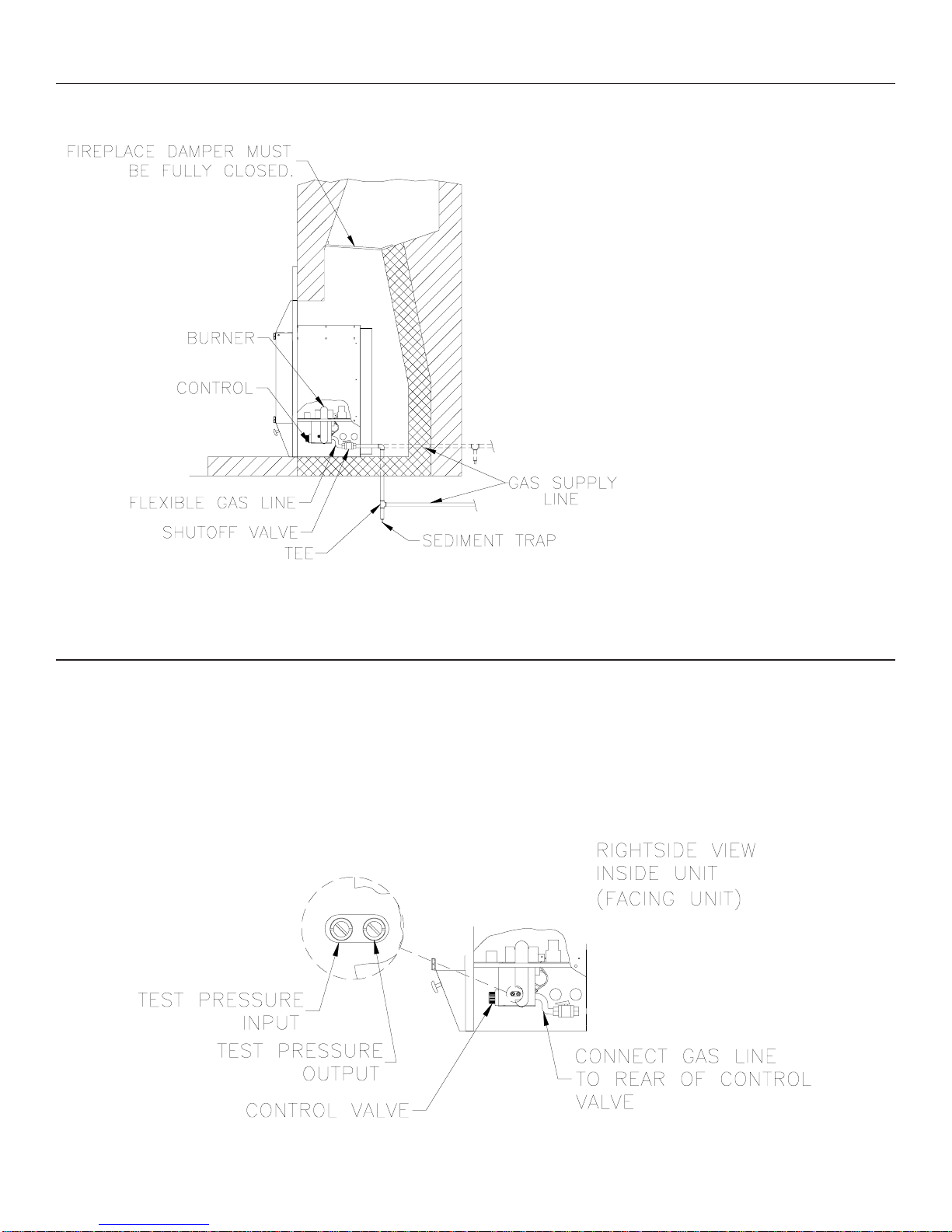
The gas inlet connection is 3/8" NPT. Connect
gas line to gas inlet on rear of control valve
(Note: we recommend a 3/8" Flexible Gas
line. Then connect a Manual Shutoff Valve
and gas supply line as shown in FIGURES 4 &
5.
Test all gas joints from the gas meter to the
heater for leaks using soap and water solution
after completing connection. DO NOT USE
AN OPEN FLAME.
FIGURE 5. Option #2 for gas connection
GAS PRESSURE CHECK
The heater regulator controls the burner pressure which should be checked at the pressure test point located on the
right side of the main control and is accessible from the side of the gas log assembly (see FIGURE 6).
The pressure should be checked with the heater burning and the control set to high (HI).
The pressure regulator is preset and locked to avoid tampering. If the pressure is not as specified in Product
Specifications (Page 5), contact your dealer and replace the regulator.
FIGURE 6. Pressure Test Point Location
15
Page 16
WIRING BLOWER ASSEMBLY
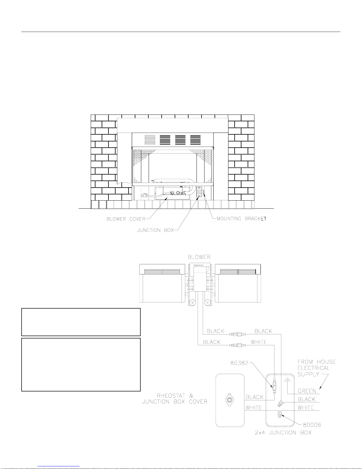
To locate the blower, open the lower access door and locate the blower cover as shown in FIGURE 7. The blower
is located directly behind the blower cover. The blower comes partially pre-wired into the junction box. To
complete wiring, run the house power supply into the heater through one of the knockouts located on either side of
the firebox. Run house supply into junction box and wire as shown in wiring diagram below(Attach grounding wire
to junction box). NOTE: Junction box and bracket comes mounted to the right side (facing unit). You can also
mount the junction box on the left side if necessary.
See "Blower replace instructions" supplied with replacement blower to remove blower.
NOTE: If any of the original wire must
be replaced, it must be replaced with
600 volt, 150 C. wire or its equivalent.
Caution: Label all wires prior to
disconnection when servicing
controls. Wiring errors can cause
improper and dangerous operation.
Verify proper operation after
servicing.
FIGURE 7. Blower Location
WIRING DIAGRAM
16
Page 17
LOGS AND LOG STOP ASSEMBLY
LOG POSITIONING
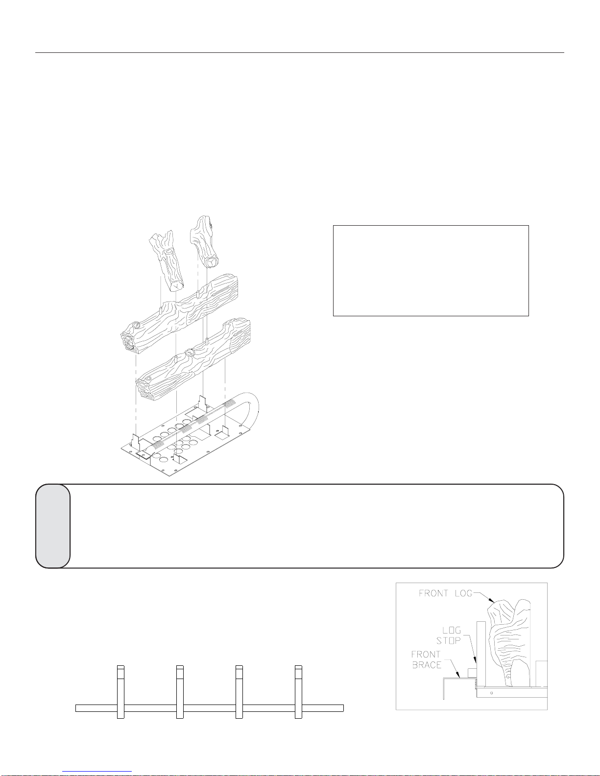
This unit is supplied with a set of four ceramic fiber logs. Do not handle these logs with your bare hands! Always
wear gloves to prevent skin irritation from ceramic fibers. After handling logs, wash your hands gently with soap
and water to remove any traces of fibers.
PROPER INSTALLATION SEQUENCE:
1. Install the rear log (#2) on the rear set of locators. Visually check to verify the log is securely placed on the
locators.
2. Install the front log (#1) on the front locators. Visually check to verify the log is securely placed on the locators.
3. Install the left and right cross twigs as illustrated, on the locator pins provided in the front and rear logs. Holes
provided in the bottom of the cross twigs should allow them to seat completely over these pins.
WARNING: Failure to position the
parts in accordance with these
diagrams or failure to use only parts
specifically approved with this heater
may result in property damage or
personal injury.
#2
#1
FIGURE 8. Log Set Assembly
The positioning of the logs is critical to the safe and clean operation of this heater.
Sooting and other problems may result if the logs are not properly and firmly
situated in the appliance. Never add additional logs or embellishments such as
WARNING
LOG STOP POSITIONING
This unit is also supplied with a decorative Log Stop. To install the Log
Stop simply place it in front of the Front Log, resting on the Front Brace as
shown in the illustration to the right.
pine cones, vermiculite or rock wool to the heater.
Cross section of firebox
17
Page 18
OPERATING INSTRUCTIONS
Avoid any drafts that alter the burner flame patterns. Do not allow fans to blow directly into the heater. Do not place
a blower inside burn area of firebox. Ceiling fans may create drafts that alter burner flame patterns. Sooting and
improper burning will occur.
This unvented gas heater is intended to be smokeless. If logs appear to smoke, turn off the heater and call a qualified
service person. Initial burn off may cause slight smoke and odor during the first four hours of operation.
FOR YOUR SAFETY READ BEFORE LIGHTING
WARNING: If you do not follow these instructions exactly, a fire or explosion may
result causing property damage, personal injury or loss of life.
WARNING
A.
B.
C.
D.
This appliance is equipped with an ignition device (Piezo) which automatically lights the pilot. If Piezo fails,
then light the pilot using matches. Refer to match lighting instructions (page 20). When lighting the pilot,
follow these instructions exactly.
BEFORE LIGHTING smell all around the appliance area for gas. Be sure to smell next to the floor because
some gas is heavier than air and will settle on the floor.
WHAT TO DO IF YOU SMELL GAS
• Do not attempt to light any appliance.
• Do not touch any electric switch; do not use any phone in your building.
• Immediately call your gas supplier from a neighbor's phone. Follow the gas supplier's instructions.
• If you cannot reach your gas supplier, call the fire department.
Use only your hand to push in or turn the gas control knob. Never use tools. If the knob will not push in or
turn by hand, don't try to repair it, call a qualified service technician. Force or attempted repair may result
in a fire or explosion.
Do not use this appliance if any part has been under water. Immediately call a qualified service technician
to inspect the appliance and to replace any part of the control system and any gas control which has been under
water.
Do not store or use gasoline or other flammable vapors and liquids in the vicinity of this or any other
appliance.
FOR YOUR SAFETY
18
Page 19
OPERATING INSTRUCTIONS
LIGHTING INSTRUCTIONS
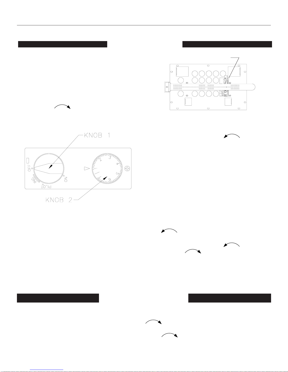
1. STOP! Read the safety information on the
previous page.
2. Turn off all electrical power and open the
access door.
3. Turn off the rear burner and set the front
burner to low.
4. Push in gas control (knob 1) slightly and turn
clockwise to "OFF".
NOTE: Knob cannot be turned from "PILOT" to
"OFF" unless knob is pushed in slightly. Do not
force.
5. Wait five (5) minutes to clear out any gas.
Then smell for gas, including near the floor. If
you smell gas, STOP! Follow "B" in the safety
information on the previous page. If you don't
smell gas, go on to the next step.
PILOT LOCATION
TOP VIEW OF BURNER ASSEMBLY
6. Push in the control (knob 1) all the way and
rotate counter-clockwise to "PILOT".
The piezo ignitor will light the pilot as the knob
passes "IGN" traveling to the "PILOT". Con
tinue to hold the control (knob 1) in for about
ten (10) seconds after the pilot is lit. Release
knob and it should pop back up. Pilot should
remain lit. If it goes out, repeat steps 4 through
6. If the control (knob 1) does not pop up when
released, stop and immediately call your ser
vice technician or gas supplier. If the pilot will
not stay lit after several tries, turn the gas
control (knob 1) to "OFF" and call your service
technician or your gas supplier.
7. Turn gas control (knob1) counter-clockwise
to "ON".
8. Set the burner (knob 2) to the desired setting
rotating counter-clockwise to MAX. and
clockwise to MIN.
9. Close access door and turn on electrical power.
1. Open access door.
2. Set burner to Min. by rotating knob clockwise until stop.
3. Unplug all electric power if service is to be performed.
4. Push in gas control knob slightly and turn clockwise to "OFF". Do not force.
5. Close access door.
TURN OFF GAS TO APPLIANCE
19
Page 20
OPERATING INSTRUCTIONS
Wait 30 seconds before readjusting the heater when the control has been turned
down to a lower setting.
WARNING
MATCH LIGHTING INSTRUCTIONS
If the pilot will not light using the piezo ignitor, you can light the pilot with a match. First, locate the pilot. The
pilot is located behind the burner tube on the right end (facing the unit), inside the firebox. To light pilot with a match,
move the gas control (knob 1, pg. 19) to the pilot position and hold down. Light match and place near pilot. Once
pilot is lit, continue to hold the knob for about ten seconds. Then follow steps 7 thru 9 on page 19.
CHECKING FLAME APPEARANCE
Flames from the pilot, front and rear burner should be visually checked when the heater is installed. In addition a
periodic visual check of the flames should be made.
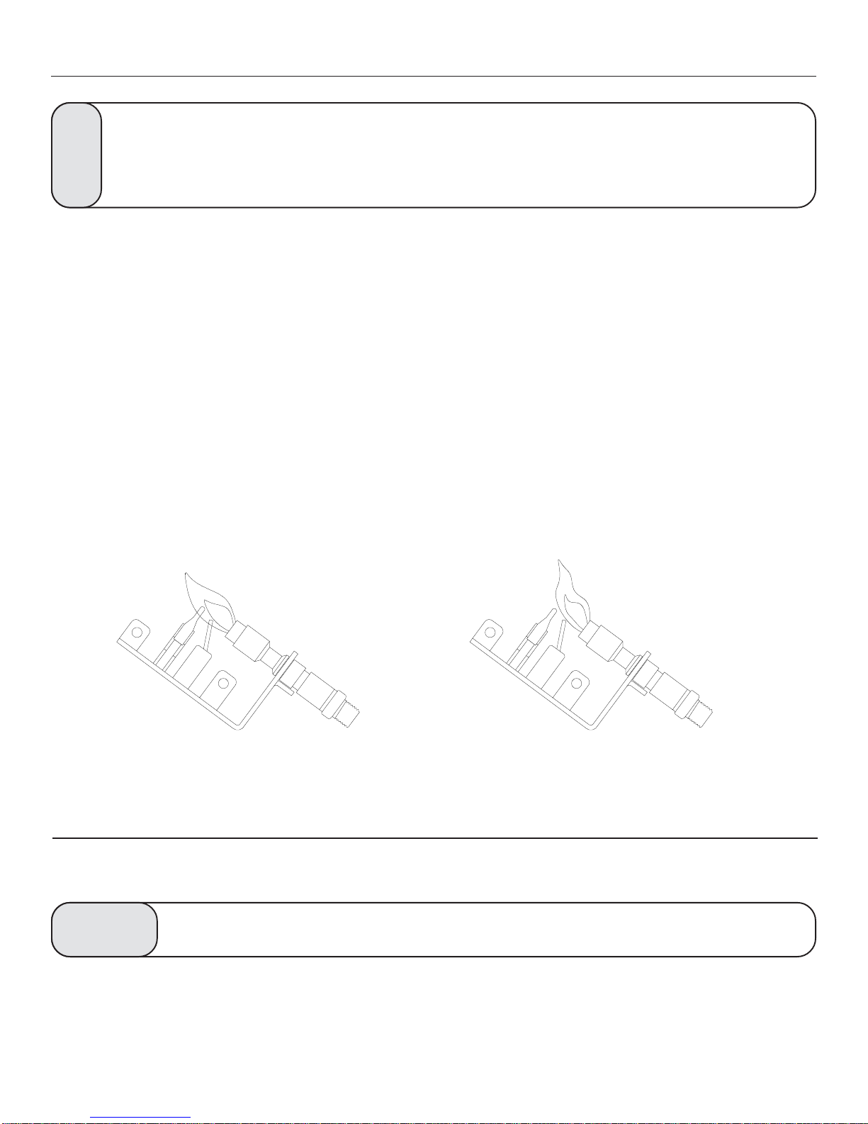
PILOT FLAME
The pilot flame should always be present when the
heater is in operation and should just touch the top of
the thermocouple tip (FIGURE 9).
If the pilot flame does not touch the thermocouple,
then the main burner is unlikely to function reliably
(FIGURE 10).
FIGURE 9. Pilot Flame
CLEANING / SERVICING
Annual inspection and cleaning by your dealer or qualified service technician is recommended to prevent
malfunction and/or sooting.
WARNING
Remove logs, handling carefully by holding gently at each end. Gloves are recommended to prevent skin irritation
from ceramic. If the skin becomes irritated, wash gently with soap and water. Refer to manual for correct log
placement.
Turn off heater and allow to cool before cleaning.
FIGURE 10. Incorrect Shape of Pilot Flame
20
Page 21
CLEANING / SERVICING
Periodic Cleaning
• Do not use cleaning fluid to clean logs or any part of heater.
• Logs - Brush with soft bristle brush or vacuum with brush attachment.
• Vacuum loose particles and dust from the front and rear burner, control, and piezo.
• Inspect burner's and air intake hole. Remove lint or particles with vacuum.
• External case should be dusted and wiped with a wet soapy cloth.
Annual Cleaning/Inspection
• Inspect and clean burner air intake holes.
• Inspect and clean all burner ports.
• Inspect ODS pilot for operation and accumulation of lint at air intake holes.
• Verify flame pattern and log placement for proper operation.
• Verify smooth and responsive ignition of the burner.
FLAME APPEARANCE
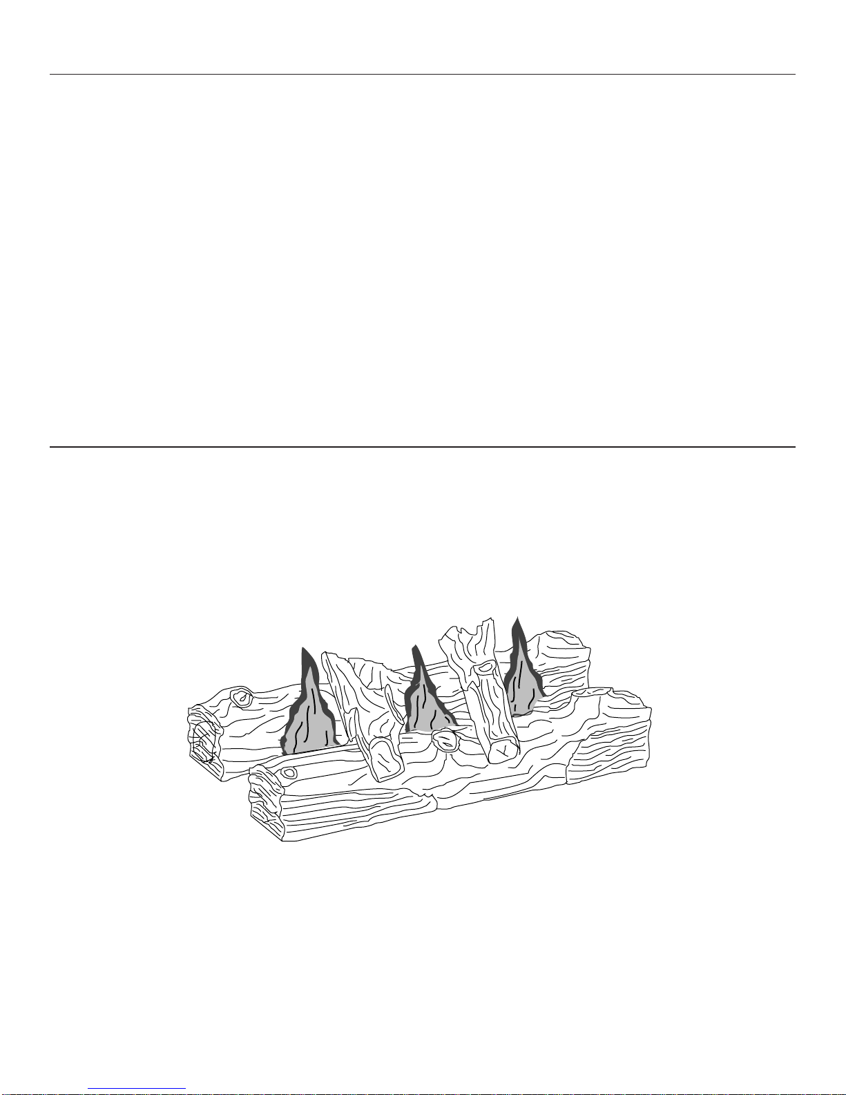
In normal operation at full rate after 15 minutes the following flame appearance should be observed.
FLAMES
The flames behind log #1, and in front of log #2, should be yellow with a blue base. The flames should
not be impinging on the small cross twigs enough to cause sooting. (See Below, Figure 11)
#2
#1
FIGURE 11. Flames - Natural Gas and LP Gas
(For illustration purposes only. See Figure 8 on page 17, for correct log placement.)
21
Page 22
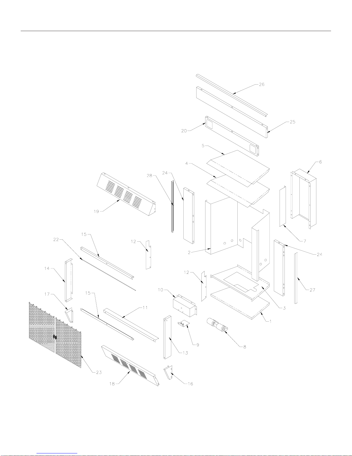
HEATER ASSEMBLY REPLACEMENT PARTS
22
Page 23

PARTS LIST FOR HEATER ASSEMBLY
KEY PART # DESCRIPTION QTY.
1 24731 CABINET BOTTOM 1
2 24732 FIREBOX 1
3 24733 FIREBOX BOTTOM 1
4 24734 INNER TOP 1
5 24735 OUTER TOP 1
6 69184 BLOWER CHANNEL 1
7 24738 DIVIDER 1
8 80337 120 CRM BLOWER 1
9 24759 BLOWER BASE 1
10 24761 BLOWER COVER 1
N/S 89390A 3/8" RUBBER GROMMET 1
11 24739 FRONT BRACE 1
12 24742 AIR SHIELD 2
13 24743 RIGHT WINDOW SIDE 1
14 24744 LEFT WINDOW SIDE 1
15 24745 WINDOW TOP/BOTTOM 2
16 24746 RIGHT SIDE COVER 1
17 24747 LEFT SIDE COVER 1
18 24748 ACCESS DOOR 1
N/S 83477 SHOULDER SCREW 4
N/S 89899 BRASS KNOB 1
N/S 83323 8-32 x 3/8" PH MACHINE SCREW 1
19 24749 TOP GRILL 1
20 24750 REAR AIR SHIELD 1
21 89659 BRASS TRIM 2
22 89902 CURTAIN ROD 1
23 89903 DRAW CURTAIN 2
N/S 83818 CLIP SPRING 2
24 24755 SIDE TRIM 2
25 24756 TOP TRIM 1
26 89905 TOP SURROUND BRASS TRIM 1
27 89906 RIGHT SURROUND BRASS TRIM 1
28 89907 LEFT SURROUND BRASS TRIM 1
N/S 83887 THERMOCOUPLE BRACKET 1
N/S = NOT SHOWN
23
Page 24
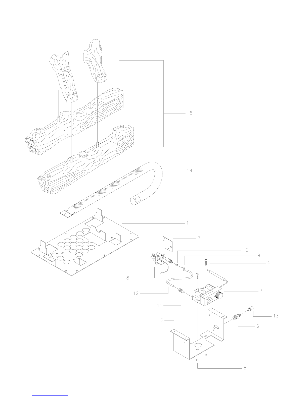
BURNER & LOG ASSEMBLY
24
Page 25

PARTS LIST FOR GAS LOG ASSEMBLY
KEY PAR T# DESC R IPTION QTY.
1 24751 BURNE R P LATE 1
2 24752 CONTROL BRACKET 1
3 81195 CONT ROL VA L VE (NATURAL) 1
81196 CONTROL VA L VE (L.P.) 1
4 83251 10-24 x 1 SL RO D 2
5 83244 10-24 KEP NUT 2
6 89831 BU RNE R /CO NTRO L FITTING 1
7 24754 PIL OT BRACKET 1
8 89872 NATURAL PILO T 1
89873 L.P. PILO T 1
9 89841 3/16 NUT 1
10 89842 3/16 COMPRESSION SLEEVE 1
11 89856 3/16 LO XIT 1
12 89855 PILO T TUBE 1
13 89909 #38 NATU R AL O RI FICE 1
89910 #.0625 L. P. ORIFICE 1
14 89904 BURNER 1
15 89826 L OG SET 1
N/S 89676 L OG ST OP W EL DMENT 1
25
Page 26

TROUBLESHOOTING
Turn off and let cool before servicing. Only a qualified service person should
service and repair heater.
WARNING
NOTE: All troubleshooting items are listed in order of operation.
OBSERVED PROBLEM
When ignitor button is pressed, there is
no spark at ODS/Pilot.
Appliance produces unwanted odors.
Appliance shuts off in use.
Gas odor even when control knob is in
OFF position.
• Ignitor electrode positioned wrong
• Ignitor electrode is broken
• Ignitor electrode not connected to ignitor
cable.
• Ignitor cable pinched or wet keep ignitor
cable dry.
• Broken ignitor cable
• Bad piezo ignitor
• Appliance burning vapors from paint, hair
spray, glues, etc.
• Gas leak.
• Not enough fresh air is available for ODS/
Pilot to operate.
• Low line pressure.
• ODS/Pilot is partially clogged.
• Gas leak.
• Control valve defective.
REMEDYPOSSIBLE CAUSE
• Replace ignitor.
• Replace ignitor.
• Reconnect ignitor cable.
• Free ignitor cable if pinched by any
metal or tubing.
• Replace ignitor cable.
• Replace piezo ignitor.
• Ventilate room. Stop using odor-causing products while heater is running.
• Locate and correct all leaks.
• Open window and/or door ventilation
• Contact local gas company.
• Clean ODS/Pilot.
• Locate and correct all leaks.
• Replace control valve.
When ignitor button is pressed, there is
spark at ODS/Pilot, but no ignition.
ODS/Pilot lights, but flame goes out
when control knob is released.
• Gas supply turned off or manual shutoff valve
closed.
• Control knob not in PILOT position.
• Control knob not pressed in while in Pilot
position
• Air in gas lines when installed.
• ODS/Pilot is clogged.
• Gas regulator setting is not correct.
• Control knob not fully pressed in.
• Control knob not pressed in long enough.
• Manual shutoff valve not fully open.
26
• Turn on gas supply or open manual shutoff
valve.
• Turn control knob while in PILOT position.
• Press in control knob while in PILOT position.
• Continue holding down control knob.
Repeat igniting operation until air is removed
• Replace ODS/pilot assembly or get is
serviced
• Replace gas regulator.
• Press in control knob fully.
• After ODS/pilot lights, keep control
knob pressed in 30 seconds.
• Fully open manual shutoff valve.
Page 27
TROUBLESHOOTING, CONTINUED...
ODS/Pilot lights, but flame goes out
When control knob is released.
(continued from page 25)
One or both burner do not
light after ODS/pilot is lit.
Burner backfires during
combustion.
Slight smoke or odor during
initial operation.
POSSIBLE CAUSEOBSERVED PROBLEM
• Thermocouple connection loose at
control valve.
• Pilot flame not touching thermocouple,
which allows thermocouple to cool,
causing pilot flame to go out. This
problem could be caused by either
low gas pressure, or a dirty or partially
clogged ODS/pilot.
• Thermocouple damaged.
• Control valve damaged.
• Burner orifice is clogged.
• Burner orifice diameter is too small.
• Inlet gas pressure is too low.
• Manifold pressure is too low.
• Burner orifice is clogged.
• Burner orifice is clogged or damaged.
• Burner is damaged.
• Gas regulator defective.
REMEDY
• Hand tighten until snug, then
tighten 1/4 turn more.
• Contact local gas company.
• Replace thermocouple.
• Replace control valve.
• Clean burner or replace burner
orifice.
• Replace burner orifice.
• Contact qualified service person.
• Contact local gas company.
• Clean burner or replace burner
orifice.
• Clean burner or replace burner
orifice.
• Replace burner.
• Replace gas regulator.
Logs appear to smoke after
initial operation.
Heater produces a whistling
noise when burner is lit.
No gas to pilot.
• Vapors from paint or curing process
of logs.
• Turning control knob to HIGH (3)
position when burner is cold.
• Air in gas line.
• Dirty or partially clogged burner
orifice.
• LP-regulator shut down due to inlet
pressure too high.
• Problem will stop after a few hours
of operation. Run the heater with
the damper open if you have one,
or open a window for the first few
hours.
• Log heater is intended to be
smokeless. Turn OFF heater and
call qualified service person.
• Turn control knob to LOW (2)
position and let warm up for a
minute.
• Operate burner until air is removed
from line. Have gas line checked
by local gas company.
• Clean burner or replace burner
orifice.
• Verify LP tank regulator is
installed and set to 11" to 13"w.c.
Replace regulator on heater.
If the gas quality is bad, your pilot may not stay lit, the burners may produce soot
and the heater may backfire when lit. If the gas quality or pressure is low, contact
your local gas supplier immediately.
WARNING
27
Page 28

OWNERS MANUAL
HOW TO ORDER REPAIR PARTS OR "OPTIONS"
THIS MANUAL WILL HELP YOU TO OBTAIN EFFICIENT, DEPENDABLE
SERVICE FROM THE FURNACE, AND ENABLE YOU TO ORDER REPAIR
PARTS CORRECTLY.
KEEP IN A SAFE PLACE FOR FUTURE REFERENCE.
WHEN WRITING, ALWAYS GIVE THE FULL MODEL NUMBER WHICH IS
ON THE NAMEPLATE ATTACHED INSIDE THE FRONT OF THE HEATER.
WHEN ORDERING REPAIR PARTS OR OPTIONS, ALWAYS GIVE THE
FOLLOWING INFORMATION AS SHOWN IN THIS LIST:
1. The PART NUMBER
I
N
U
U
2. The PART DESCRIPTION
3. The MODEL NUMBER: VF30IN VF30IL
4. The SERIAL NUMBER
BEFORE INSTALLING YOUR HEATER, FILL IN THE SERIAL
NUMBER IN THE SPACE PROVIDED ABOVE FOR YOUR
RECORDS.
T
A
E
T
S
S
D
E
T
S
C
O
M
S
A
P
S
C
Y
N
T
O
V
UNITED STATES STOVE COMPANY
E
227 Industrial Park Rd., P.O. Box 151
South Pittsburg, TN 37380
(423) 837-2100
28
 Loading...