

Page 1
OWNERS MANUAL
T
A
E
U
N
T
S
D
E
T
I
S
S
T
O
V
E
U
C
S
O
M
S
N
A
P
C
Y
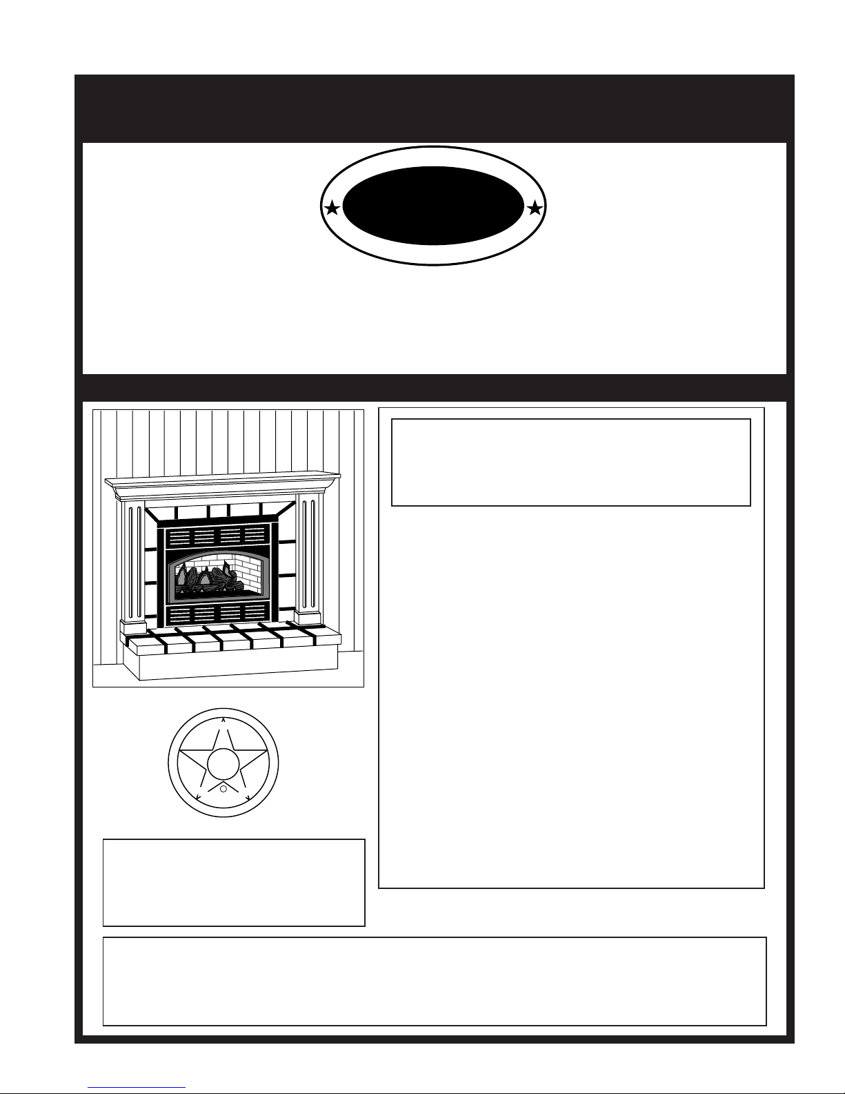
GRAVITY TYPE DIRECT
VENT WALL FURNACE
MODEL # 9660
MAY BE INSTALLED IN A MANUFACTURED HOME (MOBILE HOME).
WARNING: If the information in this
manual is not followed exactly, a fire or
explosion may result causing property
damage, personal injury or loss of life.
– Do not store or use gasoline or other
flammable vapors and liquids in the
vicinity of this or any other appliance.
– WHAT TO DO IF YOU SMELL GAS
• Do not try to light any appliance.
• Do not touch any electrical switch; do
not use any phone in your building.
• Immediately call your gas supplier from
a neighbor's phone. Follow the gas
supplier's instructions.
• If you cannot reach your gas supplier,
call the fire department.
A
S
D
M
A
S
O
C
E
G
I
S
N
E
C
I
R
A
E
GS
A
R
T
C
A
I
R
I
T
F
I
N
N
O
I
D
E
– Installation and service must be performed
United States Stove Company
227 Industrial Park Road • P.O. Box 151
South Pittsburg, TN 37380
(423) 837-2100
by a qualified installer, service agency or
the gas supplier.
Warning: Improper installation, adjustment, alteration, service or maintenance
can cause property damage, personal injury or loss of life. Refer to this manual.
Installation and service must be performed by a qualified installer, service agency
or the gas supplier.
USSC 1
NOTE: DIAGRAMS & ILLUSTRATIONS NOT TO SCALE
851172C 11/97
Page 2
INTRODUCTIONTABLE OF CONTENTS
Introduction...............................................2
Important Information................................2
Gas Specifications....................................2
Furnace Dimensions.................................3
Planning your Furnace Installation........4-5
Installation Instructions for Optional
Blower Kit.........................................5
Operation and Maintenance.................6-7
Venting Instructions..............................7-8
Venting Tables..........................................9
Pipe Installation.................................10-12
Gas Pressure Requirements.................13
Millivolt System Check...........................13
Testing Manifold & Inlet Pressure..........14
LP/Natural Gas Conversion...................14
Troubleshooting................................15-16
Lighting Instruction Label.......................17
Repair Parts (Generator Assembly).18-19
Repair Parts (Main Assembly)..........20-21
Optional Kits...........................................22
Wiring Diagrams...............................23-25
Notes................................................26-27
How To Order Repair Parts...................28
WARNING: Do not operate appliance with the
glass door removed, cracked or broken. Replacement of the glass should be done by a
licensed or qualified service person.
CAUTION: Label all wires prior to disconnection when servicing controls. Wiring errors can
cause improper and dangerous operation.
Verify proper operation after servicing.
Thank you for your purchase of the Model
9660 Gravity type vented wall furnace. By
following the instructions in this manual
you can be assured of an installation that
will add both beauty and value to your
home, as well as provide safe, efficient
supplemental heat.
Your dealer can be a valuable source of
information as well as recommending professionals who can assist in installation
and maintenance.
Improper maintenance may void warranty and can cause injury or property
damage. Refer to this manual.
IMPORTANT INFORMATION
For safe installation and operation of your
fireplace, please note the following:
1. This appliance should only be installed
by a qualified installer. Installation must
conform with local codes, or in the absence
of local codes, with the latest edition of the
National Fuel Gas Code, ANSI Z 223.11992/NFPA 54-1992.
2. A manufactured home (mobile home)
installation must conform with the
Manufactured Home Construction and
Safety Standard, Title 24 CFR, Part 3280,
or, when such a standard is not applicable ,
the Standard for Manufactured Home
Installations, ANSI A225.1/NFPA 501A.
3. Clothing or other flammable material
should not be placed on or near the
appliance.
4. The flow of combustion and ventilation
air must not be obstructed.
GAS SPECIFICATIONS
GAS MAXIMUM
MODEL FUEL CONTROL INPUT
9660N Natural Remote On/Off 24,000 BTU/HR
9660L Propane/LP Remote On/Off 20,000 BTU/HR
Manifold Pressure - Natural Gas 3.5" water column pressure
Propane/LP Gas 10" water column pressure
Gas Inlet - 3/8" NPT
SUPPLY MINIMUM PRESSURE* MAXIMUM PRESSURE
NATURAL GAS 5" W.C.P. 10.5" W.C.P.
PROPANE/LP GAS 11.0" W.C.P. 13.0" W.C.P.
*For the purpose of Input Adjustment.
5. This appliance gives off high
temperatures and should be located out of
heavy traffic areas and awa y from furniture
and draperies.
6. Children and adults should be alerted
to the hazards of the high surface
temperatures of this appliance and should
stay away to avoid burns or ignition of
clothing.
7. Children should be carefully
supervised when they are in the same room
as the fireplace.
8. Under no circumstances should this
appliance be modified. Do not operate this
appliance if any parts have been removed
for service.
9. Installation and any repairs to this
appliance should be done by a qualified
service person. A professional service
person should be called to inspect this
appliance annually. Make it a practice to
have all of your gas appliances checked
annually.
10. Control compartments, burners and air
passages in this appliance should be kept
clean and free of dust and lint. Make sure
that the gas valve and pilot light are turned
off before you attempt to clean this unit.
11. The appliance's venting system should
be inspected at least once a year and
immediately cleaned if necessary.
12. Keep the area around the appliance
clear of combustible materials, gasoline
and other flammable vapors and liquids.
Do not use this appliance as a drying rack
for clothing, nor should Christmas stockings
or decorations be hung in its immediate
area.
13. Do not operate this appliance without
glass in place. Replace damaged glass
only with equivalent glass of equal
thickness and size (available from your
dealer).
14. Never burn solid fuel (wood, paper,
cardboard, coal) in this appliance.
15. Do not use this appliance if any part
has been under water. Immediately call a
qualified service technician to inspect the
heater and to replace any part of the control
system and any gas control which has been
under water.
16. The glass must be replaced in the door ,
(if removed for service) before operating
the appliance.
2
NOTE: DIAGRAMS & ILLUSTRATIONS NOT TO SCALE
USSC
Page 3

GAS FURNACE DIMENSIONS
27 3/8
28 1/4
15 11/16
35 15/16
37 9/16
TOP VIEW*
37 9/16
32 3/4
16 1/4
*TOP VIEW SHOWN WITHOUT
FURNACE TRIM FOR CLARITY.
9 3/4
10 1/2
FRONT VIEW
USSC 3
34 7/8
3 1/2
NOTE: DIAGRAMS & ILLUSTRATIONS NOT TO SCALE
5 1/2
34 1/8
23 5/8
18 11/16
8 5/16
15 11/16
SIDE VIEW
Page 4

PLANNING YOUR FURNACE
INSTALLATION
OPENING OF DOOR
1 Remove top grill
2 Lower bottom grill by pulling
down knob.
3 Unlatch door and swing door
down.
1
3
FRAMING AND FINISHING
1. Choose furnace location and frame
opening as illustrated below in figure
3, 4a & 4b.
2. Place furnace into position and
secure to floor with nail flanges.
3. Cold climate recommendation: When
installing this furnace against a noninsulated exterior wall or chase, it is
recommended that the outer walls be
insulated to conform to applicable
insulation codes.
16" o.c.
11 1/2"
15 11/16"
HEARTH
A hearth is not required, but it will improve
the appearance and provide added safety.
We recommend a noncombustible hearth
which extends a minimum of 12 inches in
front of the appliance.
MANTELS
The height at which a mantel must be
placed above the furnace opening depends
on the depth of the mantel. See drawing
and chart (Fig. 5 & 6) for proper installation
height of a combustible mantel piece. Noncombustible mantels may be installed at
any height above the furnace opening.
NOTE: Use heat resistant paint or finish
on the mantel to prevent discoloration.
Fig. 1
2
CAUTION: DO NOT ATTEMPT TO OPEN
DOOR WHILE UNIT IS HOT.
LOCATING YOUR FURNACE
(A) Flat on wall
(B) Cross corner
NOTE: *When you install your fireplace in
(C) Flat or wall corner positions, a minimum
of 6 inches clearance must be maintained
from the perpendicular wall and the front
of the appliance.
The 9660 Gravity type vented wall furnace
may be installed flat on a combustible-floor
or raised up on a hearth to keep the flame
at eye level. If the appliance is installed
directly on carpeting, tile or other
combustible material other than wood
flooring, the appliance must be installed on
metal or wood panel extending the full width
and depth of the appliance.
B
(C) *Flat on wall corner
(D) Cantilever
A
Fig. 3
Fig. 4a
34 1/8"
Fig. 4b
12"
37 3/8"
37 3/8"
37 3/8
57 1/16"
23 5/8"
40 3/8"
12 7/8"
11 1/2"
12"
15 11/16"
28 9/16"
Fig. 5
10"
8"
6"
18"
16"
14"
12"
10"
TOP OF GRILL OPENING
WALL
4"
2"
Fig. 6 - Mantel Chart
CLEARANCE TO
COMBUSTIBLES
BACK 0 inches from standoffs
SIDES 0 inches from standoffs
FLOOR 0 inches
TOP 0 inches
CEILING 30 inches
SIDE WALL 6 inches
C
D
Fig. 2
4
Minimum wall thickness:
4 inches
Maximum wall thickness:
6 inches
NOTE: DIAGRAMS & ILLUSTRATIONS NOT TO SCALE
Non-combustibles materials such as brick,
stone or tile must extend flush with or
project in front of and/or on the face of the
fireplace but must not block any of the grill
openings or fire chamber opening.
USSC
Page 5
THIS APPLIANCE IS FOR USE WITH
NATURAL OR PROPANE/LP GAS ONLY
AS INDICATED ON RATING PLATE.
NOTE: BTU ratings shown on the rating
plate area are for elevations up to 2,000
feet. For elevations above 2,000 feet,
rating should be reduced at the rate of four
(4) percent for each 1,000 feet above sea
level.
OPTIONAL BLOWER KIT.
MODEL# B60T
Kit includes: 1-Blower Assembly
1-Speed Control Switch
1-Hardware Pack
The appliance, when installed, must be
electrically grounded in accordance with
local codes or, in the absence of local
codes, with the latest edition of the National
Electrical Code, ANSI/NFPA 70 or current.
GAS PIPE AND BURNER
INSTALLATION
Installation must conform to local codes,
or in the absence of local codes, to the
latest edition of the National fuel Gas Code,
ANSI Z 223.1-1992.
A. An accessible manual shut-off valve
is required in the gas supply line. A ground
joint union is required in the gas supply line
to provide for burner removal or servicing.
B. When a vertical section of piping is
required for installation, a condensation
trap (drip leg) is required.
C. For natural gas, a minimum of 3/8"
iron pipe with gas pressure of 5 WC must
be used for supply from the meter. Consult
with the local gas utility for any questions
concerning pipe size.
UNIT SIDE
D. A 1/8" NPT plugged tapping,
accessible for test gauges connection,
must be installed immediately up stream
of the gas supply connection to the
appliance.
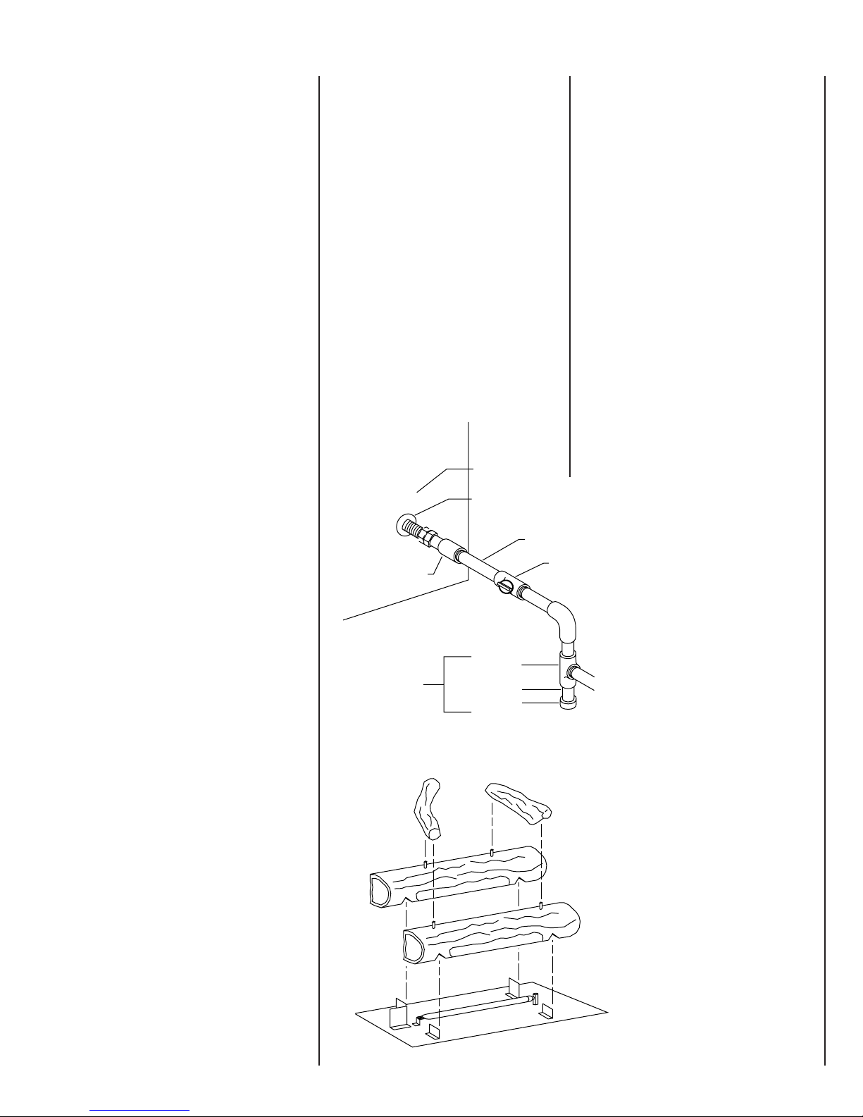
E. Make gas connection to burner
assembly with pipe or listed flexible
connection. Seal space between pipe and
knockout on firebox with high temp caulk.
See Figure 7.
F . T urn gas supply on and check for leaks
using a soap and water solution. (DO NOT
USE AN OPEN FLAME).
NOTE: The appliance and its individual
shut-off valve must be disconnected from
the gas supply piping system during any
pressure testing where the test pressure is
in excess of 1/2 psig. The appliance must
be isolated from the gas supply piping
system by closing its individual manual
shut-off valve during any pressure testing
of the gas supply piping system at test
pressure equal to or less than 1/2 psig.
INSTALLATION
1. Open bottom louver door.
2. Slide fan assembly into opening, line
up the mounting holes with the screw
studs protruding from the floor panel
and secure with the (2) nuts provided.
3. Install electrical wiring.
See B60 - Blower Kit instruction sheet for
more details (supplied with kit).
NOTE: Electrical wiring and installation
must conform to all applicable codes and
ordinances and must be done by a qualified
electrician.
CAUTION: Electrical power supply must
be disconnected prior to servicing the fan.
PIPE COUPLING
SEDIMENT TRAP
Fig. 7
SEAL THIS AREA WITH
HIGH TEMP CAULK.
PIPE
MANUAL SHUTOFF VALVE
TEE JOINT
PIPE NIPPLE
CAP
INSTALLATION OF LOGS
1. Place large rear logs against back
support bracket, flat spots up.
2. Place front log against front support
bracket, flat spots.
3. Place smaller top logs on flat spots of
bottom logs as shown in Figure 8.
4. Close Glass Door.
USSC 5
Fig. 8
NOTE: DIAGRAMS & ILLUSTRATIONS NOT TO SCALE
Page 6

OPERATION AND
MAINTENANCE
WARNING:
GAS LINE, THE GLASS FRONT MUST
BE REMOVED.
WHEN PURGING THE
LIGHTING PROCEDURE (Fig.9)
1. Depress and turn gas valve knob (A)
to "off". Wait sufficient time to allo w gas
which may have accumulated in
the burner compartment to escape. (At
least 5 minutes.)
2. Depress valve knob and turn to "pilot".
3. Depress and hold valve knob while
pushing Piezoelectric spark lighter (B).
[If pilot does not light using the piezoelectric spark lighter, the pilot can also
be lit by placing a match near the pilot
while depressing the valve knob] Hold
valve knob depressed until pilot
remains lit when knob is released
(approximately 10 seconds).
4. Turn valve knob to "ON".
5. Wait approximately one minute then
turn burner switch (C) to "ON".
6. If unit fails to start, repeat steps one
through five.
NOTE: If unit is equipped with remote "onoff" wall switch, switch must be in "on"
position for burner to light.
T
O
L
I
P
O
L
T
I
P
O
F
N
F
O
S
it
E
A
B
O
L
T
I
P
O
F
N
F
O
S
it
off
on
TP TH
TP TH
off
on
C
SHUT-DOWN PROCEDURE
1. To tur n off the Main Burner only, use
Main Burner switch or turn Valve Knob to
"PILOT" position.
2. For complete shut down, slightly depress
Valve Knob, turn to "OFF" position.
3. The Burner Assembly has been preadjusted for proper flame control. DO NOT
ALTER GAS ORIFICE. Unless con v erting
from LP to Natural or Vice Versa.
4. Periodic visual checks of the Pilot Flame
should be conducted to ensure that the
flame is continuously present except when
the valve knob is in the "OFF" position.
PILOT BURNER
ADJUSTMENT (Fig. 10)
1. Adjust pilot key to provide properly
sized flame. The flame should cover
the upper 3/8" of the tip.
2. Test for leaks.
Pilot Key
T
O
L
I
O
L
T
I
P
O
F
N
F
O
S
it
E
A
Fig. 10 - Pilot flame adjustment
P
TP TH
TP TH
7. Ignite pilot - see Lighting Procedure
Section.
8. Operate the burner and visually check
to make sure the flame pattern
appears similar to Figure 11.
NOTE: It is important to periodically
perform a visual check of the pilot and the
burner flame and to compare then with this
illustration.
Fig. 11
ADJUSTING THE FLAME
If flame is too low:
1. Open the glass door.
2. Remove the (2) top small logs and
the front log.
3. Adjust the flame higher by closing
the air shutter using a standard phillips
screwdriver.
If flame is too high:
1. Open the glass door.
2. Remove the (2) top small logs and
the front log.
3. Adjust the flame lower by opening
the air shutter slightly using a standard
phillips screwdriver.
4. CAUTION: Do not open the air
shutter to the point where the flame is
lifting off of the burner.
NOTE: If you cannot achieve sufficient
flame height, contact your local gas supplier
to check for proper gas pressure.
Fig. 9
A
NOTE: The gas control is designed to be
either fully on or off. Never use control to
vary flame height.
NOTE: It is normal for the new furnace to
give off some odor the first time it is burned.
This is due to the curing of the paint and
any undetected oil from the manufacturing
process.
It is recommended that you burn your new
fireplace for at least two (2) hours the first
time you use it. If optional fan kit is installed,
leave it turned off during this break-in
period.
6
MAINTENANCE
It is important to keep burner and the
burner compartment clean. This must
be done periodically, at least once per
season.
Steps for Cleaning Procedure:
1. Turn off pilot.
2. Open glass door frame assembly.
3. Remove logs.
4. Vacuum burner compar tment,
especially around the orifice opening.
5. Reinstall logs.
6. Close glass door frame.
NOTE: DIAGRAMS & ILLUSTRATIONS NOT TO SCALE
USSC
Page 7
GLASS CLEANING
It will be necessary to clean the glass
periodically. During start-up, condensation
forms on the inside of the glass and causes
dust, lint, etc. to cling to the glass surface.
This is normal. Also, initial paint curing can
deposit a slight film on the glass.
DO NOT CLEAN GLASS WHEN IT IS
HOT.
DO NOT USE ABRASIVE CLEANERS ON
GLASS OR DOOR.
IMPORTANT! THE VENT-AIR INTAKE
SYSTEM MUST BE PROPERLY INSTALLED TO INSURE PROPER AND
SAFE OPERATION. THE VENT-AIR INTAKE SYSTEM MUST BE PROPERLY
REINSTALLED AND RESEALED TO INSURE PROPER AND SAFE OPERA TION.
FOR MANUF A CTURED HOME (MOBILE
HOME) INSTALLATION: "THIS APPLIANCE MUST BE INST ALLED IN ACCORDANCE WITH THE MANUFACTURER'S
INSTRUCTIONS AND THE
MANUFACTURER'S HOME CONSTRUCTION AND SAFETY STANDARDS, TITLE CFR, P ART 3280."
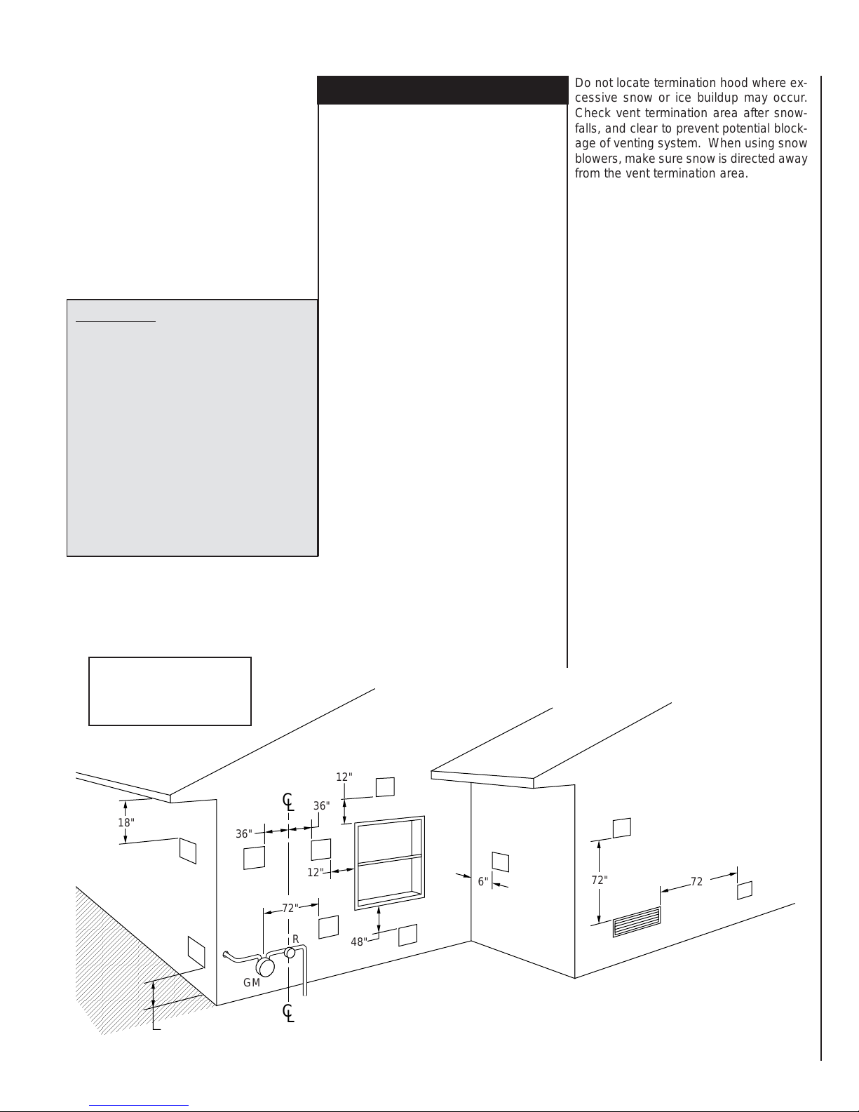
V - Vent Termination
M - Mechanical Air
GM- Gas Meter
R - Regulator
VENTING INSTRUCTIONS
The Model 9660 furnace is designed for
direct venting through a side wall or roof.
Only venting components specifically
approved and labeled for this furnace may
be used. The flow of combustion and
ventilation air must not be obstructed.
Minimum clearance between vent pipes
and combustible materials is one (1) inch.
CAUTION: ALL JOINTS MUST
BE AIR-TIGHT.
THE INSTALLATION OF THIS
APPLIANCE MUST CONFORM WITH
LOCAL CODES, OR IN THE ABSENCE
OF LOCAL CODES, WITH THE LATEST
EDITION OF THE NATIONAL FUEL GAS
CODE, ANSI 223.1 (Latest Edition).
SIDE WALL VENTING
Location of Vent Termination
IMPORTANT: The minimum clearances
given for the vent termination must be
strictly adhered to. There must not be any
obstruction such as bushes, fences, garden
sheds, decks or utility buildings within 24"
from the front of the termination hood.
Do not locate termination hood where excessive snow or ice buildup may occur.
Check vent termination area after snowfalls, and clear to prevent potential blockage of venting system. When using snow
blowers, make sure snow is directed away
from the vent termination area.
The vent termination must not be located:
1. Less than 7 feet above a paved
sidewalk or a paved driveway
located on public property.
2. Within 6 feet of a mechanical air sup-
ply inlet to any building.
3. Above a meter/regulator assembly
within 3 feet horizontally of the verti-
cal center-line of the regulator.
4. Within 6 feet of any gas service
regulator vent outlet.
5. Less than 1 foot above grade level;
(see section on below ground
installation for special venting.)
6. Within the following distances of a
window or a door which can be
opened, any non-mechanical air
supply inlet or the combustion air in-
let of another appliance;
a. 12 inches top and sides.
b. 4 feet below.
7. Underneath a veranda, porch or deck
where,
a. the veranda, porch or deck is fully
open on a minimum of two sides
beneath the floor.
b. the distance between the top of
the vent termination and the underside of the veranda, porch, or deck is
less than 4 feet.
C
L
18"
V
36"
V
72"
V
GM
C
12"
L
MINIMUM VENT TERMINATION CLEARANCES
From combustible's exterior surfaces, gas meter, air intakes, etc.
USSC 7
12"
V
36"
V
V
12"
V
R
48"
NOTE: DIAGRAMS & ILLUSTRATIONS NOT TO SCALE
V
V
6"
72"
72"
M
V
Page 8
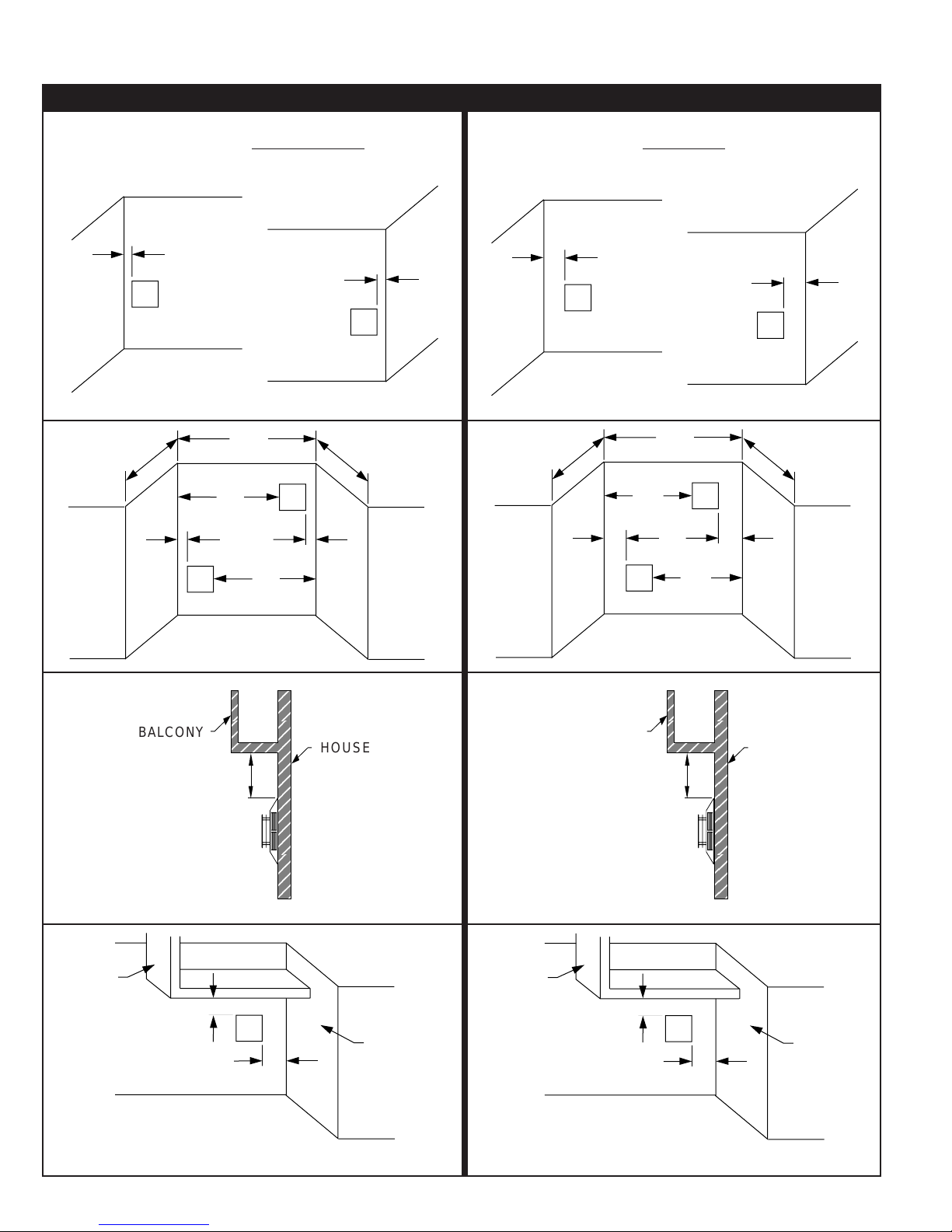
VENTING INSTRUCTIONS
If the exterior of the building is non-combustible the following
minimum clearances are applicable:
2"
2"
INSIDE CORNER
OUTSIDE CORNER
12"
2"
24"
48"
2"
12"
48"
If exterior of the building is combustible the following minimum
clearances are applicable.
6"
6"
INSIDE CORNER
OUTSIDE CORNER
48"
36"
12"
6"
12"
48"
6"
BALCONY
RECESSED LOCATION
BALCONY
18"
BALCONY - NO SIDE WALL (CROSS SECTION)
24"
20"
HOUSE EXTERIOR
WALL
SIDE
WALL
RECESSED LOCATION
BALCONY
24"
BALCONY - NO SIDE WALL (CROSS SECTION)
BALCONY
24"
20"
HOUSE
EXTERIOR
WALL
SIDE
WALL
BALCONY WITH PERPENDICULAR SIDE WALL
8
BALCONY WITH PERPENDICULAR SIDE WALL
NOTE: DIAGRAMS & ILLUSTRATIONS NOT TO SCALE
USSC
Page 9

VENTING TABLES
H
V
H
V
1
V
T
1
TABLE C
V
T
TABLE A
TABLE A
V = 40' Max.
T
H
TABLE D
TABLE D
H = 12" Min.
H = 24" Max.
V
T
H
TABLE B
TABLE B
VH
T
Min. Max.
12
24
36
48
58
V = 40 Max.
T
H = 8' Max.
H
TOP VIEW
VHH+HV
Min. Max. Max. Max.
12239
24438
36637
48836
5 8 10 35
6 8 12 34
7 8 14 33
8 8 16 32
9 8 16 31
TABLE C
1
V = V+V = 40' Max.
T
1
H = 8' Max.
1
TABLE E
TABLE E
H = 12" Min.
H = 24" Max.
TABLE F
VHH+H
Min. Max. Max.
122
V
244
366
488
H
1
H
T
TABLE F-1
H
5810
6812
7814
8816
9816
V = 20' Max.
H = 8' Max.
H = H+H = 16' Max.
T
1
1
V
H
1
H
H
T
TABLE F-2
(variation with
3 elbows)
USSC 9
NOTE: DIAGRAMS & ILLUSTRATIONS NOT TO SCALE
Page 10
INFORMATION ON VENTING
ROUTES AND COMPONENTS
Since it is very important that the vent
system maintain its balance between the
combustion air intake and the flue gas
exhaust, certain limitation as to vent
configurations apply and must be strictly
adhered to.
• Max. vertical vent run is 40 ft.
• Max. horizontal vent run is 16 ft.
• A 1/4" rise per foot of horizontal run
must be maintained on all horizontal
runs.
• It is possible to configure a venting
system with 40 feet of vertical vent run
and 16 feet of horizontal vent run and
include up to (3) three elbows.
(See venting tables on page 9.)
IMPORTANT: It is always best to locate
the furnace in such a way that a minimum
of offsets and/or horizontal run is required.
INSTALLATION
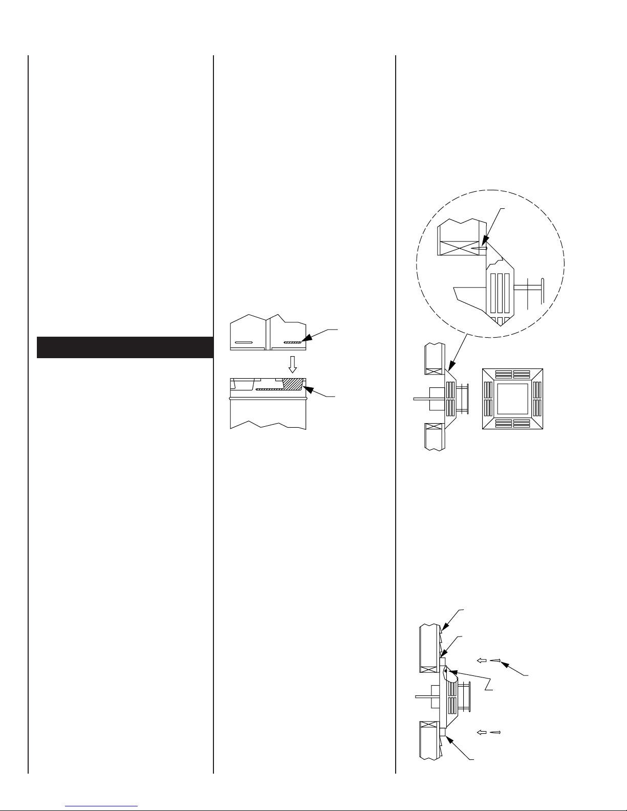
(1) Twist-lock procedure: Four
indentations, located on the female
ends of pipes and fittings, are
designed to slide straight onto the
male ends of adjacent pipes and
fittings, by orienting the four pipe
indentations so they match and slide
into the four entry slots on the male
ends. (Figure 12) Push the pipe
sections completely together, then
twist-lock one section clockwise
approximately one-quarter turn, until
the two sections are fully locked. The
female locking lugs will not be visible
from the outside, on the Black Pipe
or fittings. They may be located by
examining the inside of the female
ends.
(2) Horizontal runs of vent must be
supported every three feet. Wall
Straps are available for this purpose.
FEMALE
LOCKING
LUGS
STEP 4:
Position the horizontal vent termination in
the center of the 11 1/2" x 12" hole, and
attach to the exterior wall with the four wood
screws provided. Before attaching the V ent
T ermination to the exterior wall, run a bead
of non-hardening mastic around it's outside
edges, so as to make a seal between it and
the wall. The arro w on the vent cap should
be pointing up. Insure that proper
clearances to combustible materials are
maintained. (Figure 14)
WOOD
SCREWS
PLANNING YOUR
INSTALLATION
When planning your installation, it will be
necessary to select the proper length of
vent pipe for your particular requirements.
To determine the length of vent pipe
required for vertical installations, measure
the distance from the appliance flue outlet
to the ceiling, the ceiling thickness, the
vertical rise in an attic or second story, and
allow for sufficient vent height above the
roofline. For two-story applications,
firestops are required at each floor level. If
an offset is needed in the attic, additional
pipe and elbows will be required.
HORIZONTAL INSTALLATION
STEP 1:
Set the gas appliance in it's desired
location. Check to determine if wall studs
or roof rafters are in the way when the
venting system is attached. If this is the
case, you may want to adjust the location
of the appliance.
STEP 2:
Direct Vent pipe and fittings are designed
with special twist-lock connections. To
connect the venting system to the
appliance flue outlet, we have supplied a
twist-lock appliance adaptor built into the
unit at the factory.
MALE
LOCKING
LUGS
Fig. 12
STEP 3:
With the adaptor and pipe attached to the
stove into it's correct location, and mark the
wall for a 11 1/2-inch x 12-inch square hole.
The center of the square hole should line
up with the centerline of the horizontal pipe,
as shown in Figure 13. Cut and frame the
square hole in the exterior wall where the
vent will be terminated. If the wall being
penetrated is constructed of noncombustible material, i.e. masonry block or
concrete, a 7-inch diameter hole
is acceptable.
(1) The horizontal run of vent must ha ve
a 1/4-inch rise for every 1 foot of run
towards the termination. Never allow the
vent to run downward. This could cause
high temperatures and may present the
possibility of a fire.
(2) The location of the horizontal vent
termination on an exterior wall must meet
all local and national building codes, and
must not be easily blocked or obstructed.
Termination clearances are given on
page 7 & 8.
HOT
Fig. 13
NOTE:
(1) The four wood screws provided
should be replaced with appropriate
fasteners for stucco, brick, concrete, or
other types of sidings.
(2) For buildings with vinyl sidings, a
Vinyl Siding Standoff (Part 950), should
be installed between the vent cap and
the exterior wall. (Figure 14). Attach the
Vinyl Siding Standoff to the Horizontal
Vent Termination. The Vinyl Siding
Standoff prevents excessive heat from
possibly melting the vinyl siding material.
VINYL
SIDING
APPLY SEALANT
TO ALL FOUR SIDES
SCREWS
BOLT HORIZONTAL
TOP TO VINYL
STANDOFF
VINYL SIDING
Fig. 14
STANDOFF
10
NOTE: DIAGRAMS & ILLUSTRATIONS NOT TO SCALE
USSC
Page 11

VERTICAL TERMINATION
STEP 1:
Set the gas appliance in it's desired location. Drop a plumb bob down from the
ceiling to the position of the appliance flue
exit, and mark the location where the vent
will penetrate the ceiling. Drill a small hole
at this point. Next, drop a plumb bob from
the roof to the hole previously drilled in
the ceiling, and mark the spot where the
vent will penetrate the roof. Determine if
ceiling joists, roof rafters, or other framing
will obstruct the venting system. You may
wish to relocate the appliance, or to offset,
as shown in Figure 15, to avoid cutting
loadbearing members.
PLUMBER'S TAPE
CONNECTED TO
WALL STRAP
STEP 2:
T o install the round support box/wall thimble
in a flat ceiling, cut a 11 1/2" x 12" hole in
the ceiling, centered on the hole drilled in
Step 1. Frame the hole as shown in Figure
16.
STEP 3:
Assemble the desired lengths of Pipe and
Elbows necessary to reach from the
Appliance adaptor up through the Round
Support box. Insure that all Pipe and Elbow
connection are in their fully twist-licked
position.
STEP 4:
Cut a hole in the roof centered on the small
drill hole placed in the roof in STEP 1. The
hole should be of sufficient size to meet
the minimum requirements for clearance
to combustibles, as specified on page 8.
Continue to assemble lengths of Pipe and
Elbows necessary to reach from the Ceiling
Support Box up through the roof line. A
galvanized finish is desirable above the
roofline, due to it's higher corrosion
resistance.
(1) If an offset is necessary in the attic to
avoid obstructions, it is important to
support the vent pipe every 3 feet, to
avoid excessive stress on the Elbows,
and possible separation. W all Straps are
available for this purpose.
(2) Whenever possible, use 45 degrees
Elbows, instead of 90 degrees Elbows.
The 45 degrees Elbows offers less
restriction to the flow of flue gases and
intake air.
STEP 5:
Slip the flashing over the Pipe Section(s)
protruding through the roof. Secure the
base of the Flashing to the roof with roofing
nails. Insure the roofing material overlaps
the top edge of the Flashing as shown in
Figure 18. Verify that you ha ve at least the
minimum clearance to combustibles at the
roofline.
CAP AND STORM
COLLAR NOT SHOWN
FOR CLARITY
WALL STRAP
Fig. 15
(2) 45
ELBOWS
FRAMING
SHINGLES OVERLAP
TOP EDGE OF
FLASHING
CEILING JOIST
Fig. 17
11 1/2"
12"
1-1/2 INCH LONG
WOOD SCREWS
Fig. 16
USSC 11
NOTE: DIAGRAMS & ILLUSTRATIONS NOT TO SCALE
Page 12

STEP 6:
Continue to add pipe sections until the
height of the Vent Cap meets the minimum
building code requirements described in
figure 18. Note that for steep roof pitches,
the vent height must be increased. In high
wind conditions, nearby trees, adjoining
rooflines, steep pitched roofs, and other
similar factors can result in poor draft, or
down-drafting. In these cases, increasing
the vent height may solve this problem.
Nail
Firestop
STEP 7:
Twist lock the Vent Cap.
NOTE:
(1) For multistory vertical installations, a
Ceiling Firestop is required at the second
floor, and any subsequent floors. (Fig. 19)
The opening should be framed to 11-1/2inch x 12-inch inside dimensions, in the
same manner as shown in Figure 16, page
11.
(2) Any occupied areas above the first
floor, including closets and storage
spaces, which the vertical vent passes
through, must be enclosed. The enclosure
may be framed and sheetrocked with standard construction materials, see page 8
for minimum allowable clearance between
the outside of the vent pipe, and the combustible surfaces of the enclosure. Do not
fill any of the required air spaces with insulation.
IMPORTANT NOTICE:
If for any reason it becomes necessary to
remove the unit for maintenance and the
Dura-vent pipe is detached, the piping
MUST be resealed using HEA T SAFE high
temperature sealant, available at your local hearth and heating store.
2 7/16"
2 7/16"
3 15/16"
2 7/16"
Fig. 19
BUILDING CODE REQUIREMENTS
ROOF PITCH MINIMUM HEIGHT
FEET
FLAT TO 7/12 1
OVER 7/12 TO 8/12 1.5
OVER 8/12 TO 9/12 2
OVER 9/12 TO 10/12 2.5
OVER 10/12 TO 11/12 3.25
OVER 11/12 TO 12/12 4
OVER 12/12 TO 14/12 5
OVER 14/12 TO 16/12 6
OVER 16/12 TO 18/12 7
OVER 18/12 TO 20/12 7.5
OVER 20/12 TO 21/12 8
12
H
Fig. 18
NOTE: DIAGRAMS & ILLUSTRATIONS NOT TO SCALE
USSC
Page 13

GAS PRESSURE REQUIREMENTS
The number one cause of all operating
problems with gas appliances is
improper gas pressure!
Such problems as changes in flame
color or configuration, gas pilot or burner
outages, intermittent operation, changes in
heat output, excessive burner noise, etc.,
are nearly always the result of changes in
gas pressure or improper gas pressure at
the time of the installation.
The most important item to check
during the initial installation and the first
thing to check when operating problems
occur is gas pressure!
Gas supplies normally enter a typical
residence at 1/2 PSI (13"-15"W.C .) (3.KP A).
A regulator is then placed inside the
residence which drops this pressure to 7"
W.C. (1.8KPS) (Nat. Gas).
This "inches to inches" regulator is of
adequate capacity to service the gas
appliances such as water heater, dryer,
furnace, etc.
If this regulator's capacity is not
sufficient to add the Model 9660, an
additional "inches to inches: regulator must
be installed specifically for the fireplace.
EXCEPTION: some codes allow 2 PSI
(1.4KPA) supplies to enter the residence,
in which case "pounds to inches" regulators
are used.
The following table provides
information on correct gas pressure
requirements. Be sure your gas supplier
or plumber carefully follows this table
when installing your gas appliance.
DESIRED MINIMUM MAXIMUM MANIFOLD AIR SHUTTER
PRESSURE PRESSURE PRESSURE PRESSURE POSITION
NATURAL 7.0" W.C. 5.0" W.C.* 10.5" W.C. 3.5" W.C. 5/16" OPEN
L.P. 11.0" W.C. 10.0" W.C.* 13.0" W.C. 10" W.C. 5/16" OPEN
*For the Purpose of Input Adjustment.
MILLIVOLT SYSTEM CHECK
The millivolt system and individual
components may be checked with a
millivolt meter having a 0-1000 MV range.
Before checking the system, be certain the
wall thermostat lead wire does not exceed
the length recommended in the Wiring
Section Table, and all connections are
clean and tight.
Conduct each check shown in the
chart below by connecting meter test leads
to terminals as indicated. All readings are
closed circuit.
If the reading is more than 100 millivolts
and the automatic valve does not come on,
replace the valve operator. If the closed
circuit reading is less than 100 millivolts,
determine the cause by preceding with
steps "B" and "C".
Component Connect Wall Meter See
Check Meter Test Thermostat Reading Check
Leads To Contacts Should Be Results
Terminals Should Be Below
Valve Operator Greater Than
System 2 & 3 Closed 100 MV A
Wall Less Than
Thermostat 1 & 3 Closed 80 MV C
Thermopile Greater Than
and Magnet 1 & 2 Open 325 MV B
C. TEST RESULTSB. TEST RESULTSA. TEST RESULTS
If "B" reading is less than 325 MV, clean
and tighten all electrical connections and
adjust pilot if necessary to increase millivolt
output. If unable to adjust to at least the
specified minimum, change the thermopile.
When proper thermopile output is obtained,
the magnet may then be checked. With
pilot in operation, allow meter reading to
stabilize. Extinguish pilot burner and note
meter reading at dropout point of magnet.
If magnet remains locked up to a reading
of 120 MV or less, the magnet is good.
If "C" reading is more than that specified
for the system being checked, clean and
tighten thermostat leads and connection,
shorten lead wires if possible or use heavier
gauge wire. Rapidly cycle thermostat to
clean contacts, or change the thermostat.
USSC 13
NOTE: DIAGRAMS & ILLUSTRATIONS NOT TO SCALE
Page 14
TESTING MANIFOLD AND
INLET PRESSURE
GAS
CONVERSION
6. Rotate the conversion cap until the
desired gas designation is exposed and
reinstall it in the control.
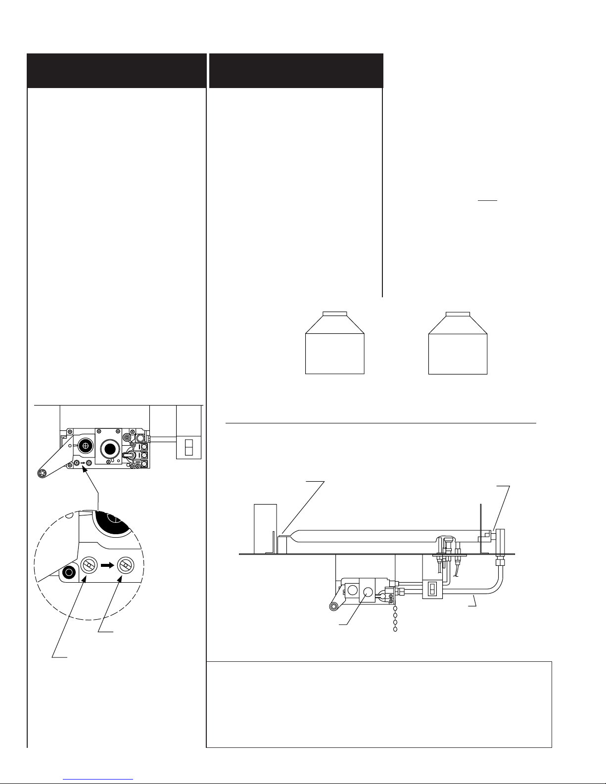
T o test the Manif old gas pressure and Inlet
gas pressure in the field, simply follow the
instructions below.
NOTE: Manometer attachment may be
accomplished by sliding a rubber tube connected to the manometer to the pressure
taps.
1. Locate the Manifold and Inlet pressure
taps on the control. (See Figure 20)
NOTE: The following instructions
apply for both the Manifold and Inlet
pressure tests.
2. With a small screwdriver, rotate the
screw in the pressure tap "counterclockwise" until loosened. NOTE:
Screw is designed not to come
completely out.
3. Attach Manometer to pressure tap and
take reading.
4. Once testing is complete, rotate the
pressure tap screw "clockwise" and
tighten securely.
1. Open lower door and locate the 1/4"
O.D. tubing connecting the control to the
bottom of the pilot.
2. Loosen the nut on the tubing at the pilot
completely then gently pull down on the
pilot tubing to expose the pilot orifice.
(Fig. 21)
3. Remove pilot orifice and put correct
orifice for the desired gas on the end of
the tubing. (Fig. 21)
4. Reinstall the pilot supply tubing, with
orifice, in the base of the pilot and
tighten nut.
5. Next, locate the conversion cap on the
control and remove it. (Fig. 22)
Fig. 21
30 51
LP Pilot Orifice Natural Pilot Orifice
7. Open glass door and remove the
ceramic logs.
8. Remove burner screw and then remove
burner.
9. Unscrew burner orifice and install orifice
for the gas to be used as identified on
the unit rating plate. When installing
the new orifice you
must use a pipe
sealant approved for use with Natural
and LP gas.
10.Install burner and burner screw.
11.Check for gas leaks at all connections.
12.Replace ceramic logs and close glass
door.
Fig. 20
T
O
L
I
O
L
T
I
P
O
F
N
F
O
S
it
E
A
P
E
A
MANIFOLD
PRESSURE TAP
INLET PRESSURE
TAP
LP Pilot orifice will be color coded BLACK.
off
TP TH
TP TH
on
Fig. 22
Remove screw with
philips driver to
lift burner
Conversion Cap
Main Orifice
(Remove with
7/16 wrench)
Orifice for
Conversion will
be attached to
piping here
Warning! Improper installation, adjustment, alteration, service or maintenance can
cause injury or property damage. For assistance or additional information consult a
qualified installer, service agency or the gas supplier.
14
Due to high surface temperatures, keep children, clothing and furniture away.
Keep burner and control compartment clean.
NOTE: DIAGRAMS & ILLUSTRATIONS NOT TO SCALE
USSC
Page 15

TROUBLESHOOTING
PROBLEM: POSSIBLE CAUSES: REMEDIES:
Piezo sparker won't light pilot. 1. Misaligned electrode. 1. Realign electrode so it produces
spark into pilot hood (approximately
1/8" from pilot hood).
2. Incorrect wire connections. 2. Make sure connections are proper.
3. Defective electrode. 3. Replace electrode if shorted out or it
has cracked porcelain.
4. Defective push button. 4. Replace push button.
5. No gas present. 5. Turn gas on.
PROBLEM: POSSIBLE CAUSES: REMEDIES:
Pilot will not stay lit. 1. Incorrect lighting procedure. 1. Checking lighting instructions found
on label in gas fireplace or in owners manual.
2. Pilot flame not making proper 2. Adjust pilot (see page 6).
contact with thermopile.
3. Bad connection between thermopile 3. Make sure screws are snug holding
and screw terminals on gas valve. thermopile. (Do not overtighten or
the screws will become stripped).
4. Wires on wrong terminals. 4. White lead from thermopile must go
to top screw TH TP terminal and red
wire must go to spill switch wire.
5. Ther mopile is defective, dirty, or 5. Test with millivolt meter and replace
weak. if necessary.
6. Thermopile is shorting out where it 6. Replace thermopile.
passes through cabinet.
7. Gas valve will not prove pilot. 7. Replace valve.
8. Air in line. 8. Purge air from gas line.
9. Wire from valve to wall switch or 9. Remove wall switch wires from top
remote switch is nicked or shorting and bottom screw of millivolt valve.
out. If unit is OK and you reconnect the
wall switch and it cuts out again, then
replace wires to wall switch.
10. Switch defective or short in circuit. 10. Replace switch.
PROBLEM: POSSIBLE CAUSES: REMEDIES:
Pilot stays on but main burner won't 1. Wired incorrectly. 1. See page 22 for correct wiring.
come on. 2. Wall switch, on/off switch, or remote 2. Replace wall switch, on/off switch,
PROBLEM: POSSIBLE CAUSES: REMEDIES:
Wall switch must be pushed multiple Defective wall switch. Replace wall switch.
times to make flame come on. NOTE: Can use standard single
USSC 15
hand switch defective. or remote hand switch.
3. Not enough voltage being generated 3. Adjust pilot light up to create more
by pilot. voltage or replace thermopile.
4. Defective gas control valve. 4. Replace gas control valve.
pole electrical switch.
NOTE: DIAGRAMS & ILLUSTRATIONS NOT TO SCALE
Page 16

TROUBLESHOOTING (CONT.)
PROBLEM: POSSIBLE CAUSES: REMEDIES:
Window keeps getting sooty. Unit needs more primary air.
1. Blocked primary air port. 1. Check primary air assembly. Over
a period of time dust, lint, pet hair,
etc. can plug primary air hole. Clean
out.
2. Flame impingement on logs or 2. Reposition logs or adjust flame.
elsewhere.
3. Logs too close to or touching glass. 3. Move logs to allow at least 3/8"
clearance from logs to glass.
4. Valve and burner over-fired. 4. Check the amount of flow with
monometer, and adjust regulator if
necessary.
PROBLEM: POSSIBLE CAUSES: REMEDIES:
Dirty window. (White on window). Initial burn off of paint and sealants 1. Clean window using AJAX or
used to produce unit. COMET, and paper towel.
2. Dissolve powder AJAX or powder
COMET in water on window. Clean
in small circular motions. Rinse
thoroughly and reinstall in unit. DO
NOT USE ANY LIQUID CLEANERS
ON WINDOW. It will burn black on
window when reinstalled.
NOTE: Windows are made of neo (pyro) ceramic, NOT glass. Because of this, the will handle temperatures in excess of 1,200
degrees Fahrenheit constant temperature. The window only reaches between 500-600 degrees Fahrenheit. Because of this it is
almost impossible to bake something into the window. Most things will, with a little effort, some off if you follow these directions.
PROBLEM: POSSIBLE CAUSES: REMEDIES:
Circulating fan speed does not vary. Variable speed rheostat defective. Replace rheostat.
NOTE: Only replace rheostat with a rheostat supplied b y United States Stov e Company. Light dimmer switches or incorrect rheostats
will burn out the fan motor. This will void the warranty of the fan.
PROBLEM: POSSIBLE CAUSES: REMEDIES:
Fan makes humming sound, but won't 1. Rheostat needs adjustment. 1. Adjust variable speed control.
come on. 2. Fan imellers dirty. 2. Clean fan.
3. Fan defective. 3. Replace fan.
NOTE: Make sure the f an plug-in cord is not nic ked b y decorativ e trim kits. This could cause the fan to short out and also damage the
gas valve.
PROBLEM: POSSIBLE CAUSES: REMEDIES:
Fireplace not venting. 1. Venting blocked. 1. Remove blockage.
2. Improper venting installation. 2. Check all venting connections for
proper fit.
16
NOTE: DIAGRAMS & ILLUSTRATIONS NOT TO SCALE
USSC
Page 17

TURNING GAS OFF TO APPLIANCE
1. Set the thermostat to lowest setting.
2. Turn off all electric power to the appliance if service is
to be performed.
FOR YOUR SAFETY READ BEFORE LIGHTING
WARNING: If you do not follow these instructions exactly, a fire or
explosion may result causing property damage, personal injury or loss of life.
A. This appliance has a pilot which must be lighted by
a piezo ignitor.
When lighting the pilot, follow these instructions
exactly.
B. BEFORE LIGHTING smell all around the appliance
areas for gas. Be sure to smell next to the floor because
some gas is heavier than air and will settle on the floor.
WHAT TO DO IF YOU SMELL GAS:
• Do not try to light any appliance.
• Do not touch any electric switch; do not use any phone
in your building.
• Immediately call your gas supplier from a neighbor's
phone. Follow the gas supplier's instructions.
3. Push in gas control knob slightly and turn clockwise
to "OFF". Do not force.
•If you cannot reach your gas supplier, call the fire
department.
C. Use only your hand to push in or turn the gas control
knob. Never use tools. If the knob will not push in or turn
by hand, don't try to repair it, call a qualified service
technician. Force or attempted repair may result in a fire
or explosion.
D. Do not use this appliance if any part has been under
water. Immediately call a qualified service technician to
inspect the appliance and to replace any part of the
control system and any gas control which has been
under water.
LIGHTING INSTRUCTIONS
1. STOP! Read the safety information above on this label.
2. Set the thermostat to lowest setting.
3. Open lower door.
4. Turn off all electric power to the appliance.
5. Push in gas control knob slightly and turn
clockwise to "OFF".
Gas Control Knob
Shown in "OFF"
Position
O
L
T
I
P
O
F
N
F
O
S
it
E
A
Piezo Button
NOTE: Knob cannot be turned from "PILOT" to "OFF" unless
knob is pushed in slightly. Do not force.
6. Wait five (5) minutes to clear out any gas. Then smell for
gas, including near the floor. If you smell gas, STOP!
Follow "B" in the safety information above this label. If you
don't smell gas, go to the next step.
7. Find pilot. The pilot is between the two ceramic logs,
behind the burner.
T
O
L
I
P
TP TH
TP TH
Pilot
Ceramic Logs
Burner
8. Turn knob on gas control counterclockwise to
"PILOT".
9. Push in control knob all the way and hold in. Immediately
light the pilot by pushing in on the piezo button. Continue
to hold the control knob in for about one (1) minute after,
the pilot is lit. Release knob and it will pop back up.
Pilot should remain lit. If it goes out, repeat steps 5
through 9.
If the knob does not pop up when released, stop and immediately
call your service technician or gas supplier.
If the pilot will not stay lit after several tries, turn the gas control
knob to "OFF" and call your service technician or gas supplier.
10. Turn gas control knob counterclockwise to "ON"
11. Turn on all electric power to the appliance.
12. Set thermostat to desired setting.
13. Close lower door.
851181
USSC 17
NOTE: DIAGRAMS & ILLUSTRATIONS NOT TO SCALE
Page 18
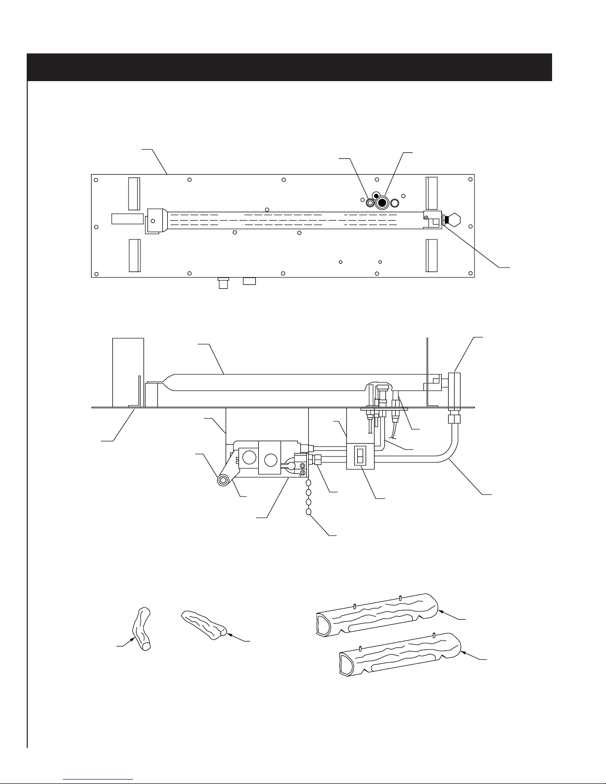
MODEL 9660 GENERATOR REPAIR PARTS
18
1
16
2
10
12
7
17
3
4
15
5
19
18
11
13
9
14
20
NOTE: DIAGRAMS & ILLUSTRATIONS NOT TO SCALE
8
6
21
22
USSC
Page 19
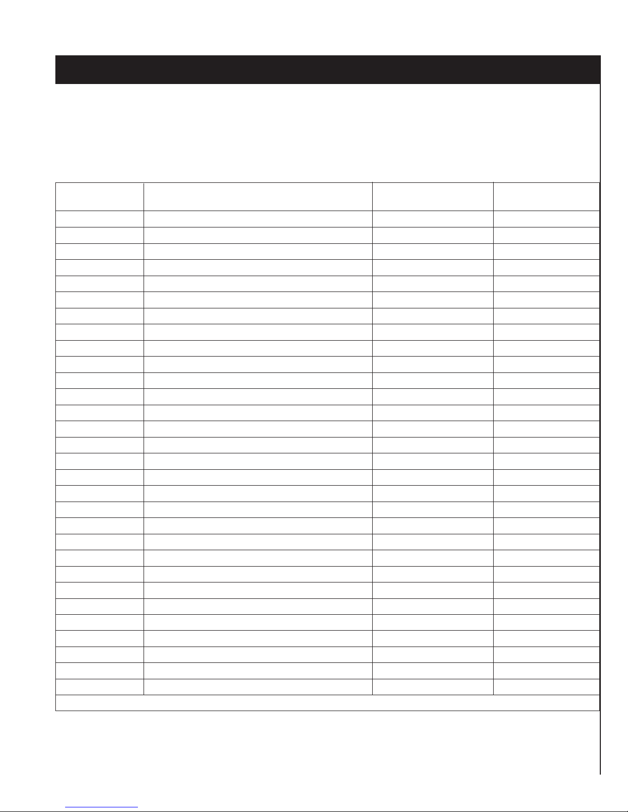
MODEL 9660 GENERATOR PARTS LIST
ITEM DESCRIPTION PART # QUANTITY
1 Control Plate Weldment 68984 1
2 Burner 89764 1
3 L.P. Burner Orifice 81185 1
* Natural Gas Burner Orifice 81184 1
4 Manifold Union 89762 1
5 1/4" OD Flex Tube 86541 1
6 3/8" OD Flex Tube 86542 1
7 Switch Bracket 24262 1
8 Rocker Switch C42373 1
9 Adaptor Fitting 81183 1
10 Control Bracket 24241 1
11 Piezo Bracket w/Screw 89760 1
12 Piezo w/ Nut 89761 1
13 Sit Control 81182 1
14 16ga. Link Chain 86318 1 FT.
15 Thermopile C43815 1
16 Sit Thermo-Couple 89759 1
17 L.P. Sit Pilot 89757 1
* Natural Gas Sit Pilot 89758 1
18 Generator Gasket 88086 1
* #8 x 1/2" Teks 83437 8
* Piezo Cable 80375 1
* Wire Assembly 80376 1
* 10-32 x 3/8 Machine Screw 83464 4
19 Top Fork Log 89771 1
20 Top Twig Log 89772 1
21 Rear Log 89770 1
22 Front Log 89769 1
* Natural Pilot Orifice 81186 1
* L.P. Pilot Orifice 81187 1
* NOT SHOWN
USSC 19
NOTE: DIAGRAMS & ILLUSTRATIONS NOT TO SCALE
Page 20
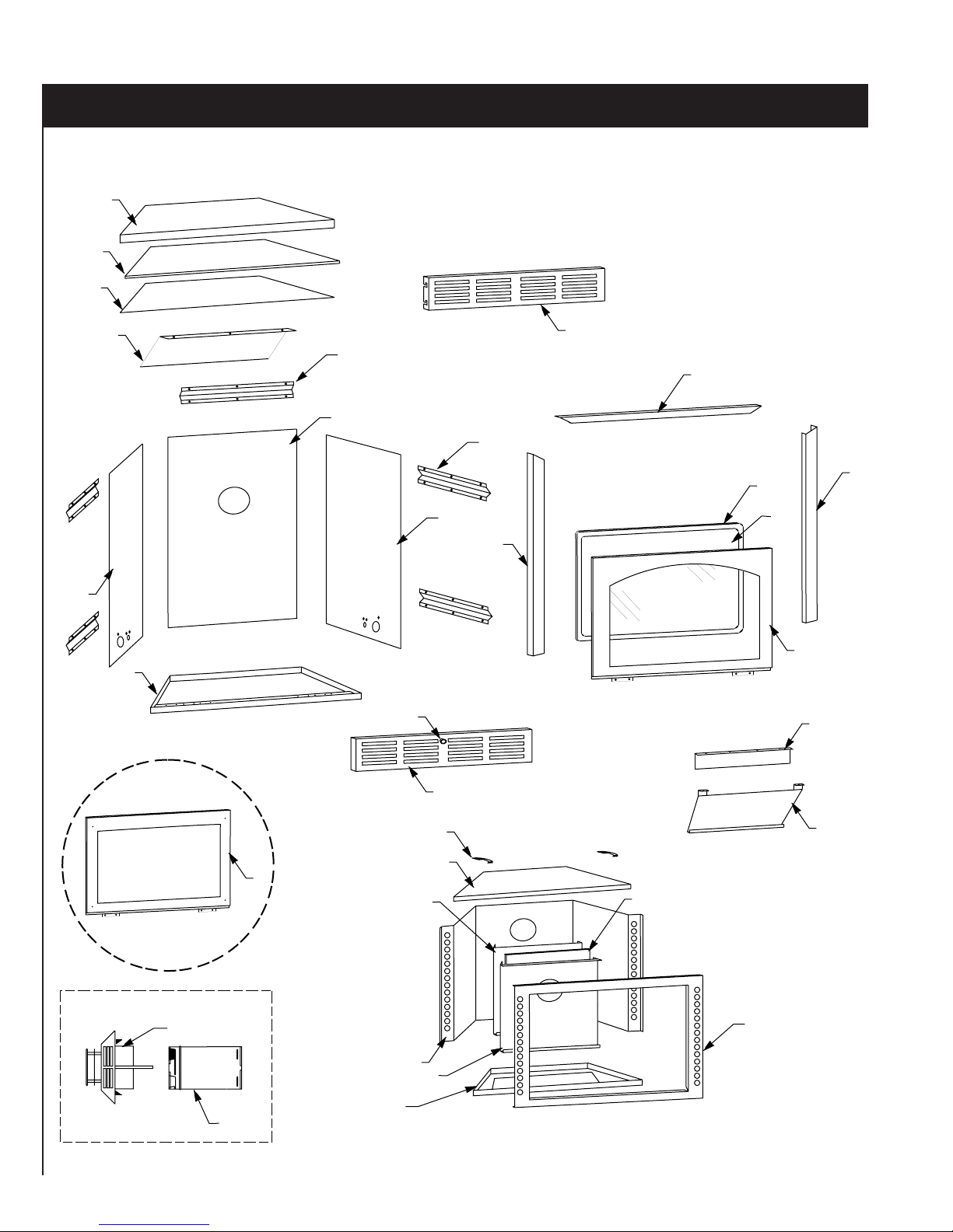
25
24
MODEL 9660 GAS FURNACE REPAIR PARTS
1
26
31
5
30
2
27
3
4
11
6
28
8
9
7
29
20
7
22
23
20
10
17
16
15
14
13
12
NOTE: DIAGRAMS & ILLUSTRATIONS NOT TO SCALE
21
18
19
USSC
Page 21
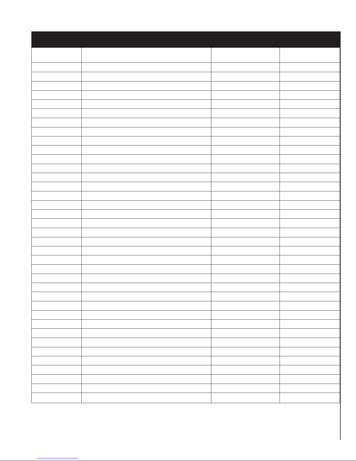
MODEL 9660 GAS FURNACE PARTS LIST
ITEM DESCRIPTION PART # QUANTITY
1 Unit Top 24249 1
2 Unit Right Side 24242 1
3 Unit Left Side 24243 1
4 Unit Base 24255 1
5 Unit Back 24246 1
6 Top Grill 24261 1
7 Arched Door Frame 68986 1
Full-view Door Frame 69046 1
8 1-1/4" Flat Rope 88087 8.042Ft.
9 Glass 89763 1
10 Lower Grill 24260 1
11 Brass Door Knob 89336 1
* 10-32x1/2" Machine Screw 83115 1
* Lower Grill Hinge C18513 2
12 Firebox Bottom 24259 1
13 Firebox Divider 24250 1
* Flue Outlet 89754 1
14 Firebox Wrapper 24253 1
* Starting Collar 89756 1
15 Firebox Shield 24265 1
16 Firebox Top 24258 1
17 Latch w/ Keeper 89755 2
18 Insulation 24266 1
19 Firebox Front 24251 1
20 Inner Baffle 24279 1
21 Baffle Plate 24252 1
22 V ent Termination Assembly 68997 1
23 12" CO-AX Pipe 89765 1
24 Insulation Shield 24269 1
25 Top Insulation 24270 1
26 Air Deflector 24280 1
27 Left Side Trim 89748 1
28 Top Trim 89749 1
29 Right Side Trim 89747 1
30 Side Standoff (2xLeft side, 2xRight side) 24278 4
31 Rear Standoff 24283 2
* Vent Standoff 24272 4
* NOT SHOWN
USSC 21
NOTE: DIAGRAMS & ILLUSTRATIONS NOT TO SCALE
Page 22
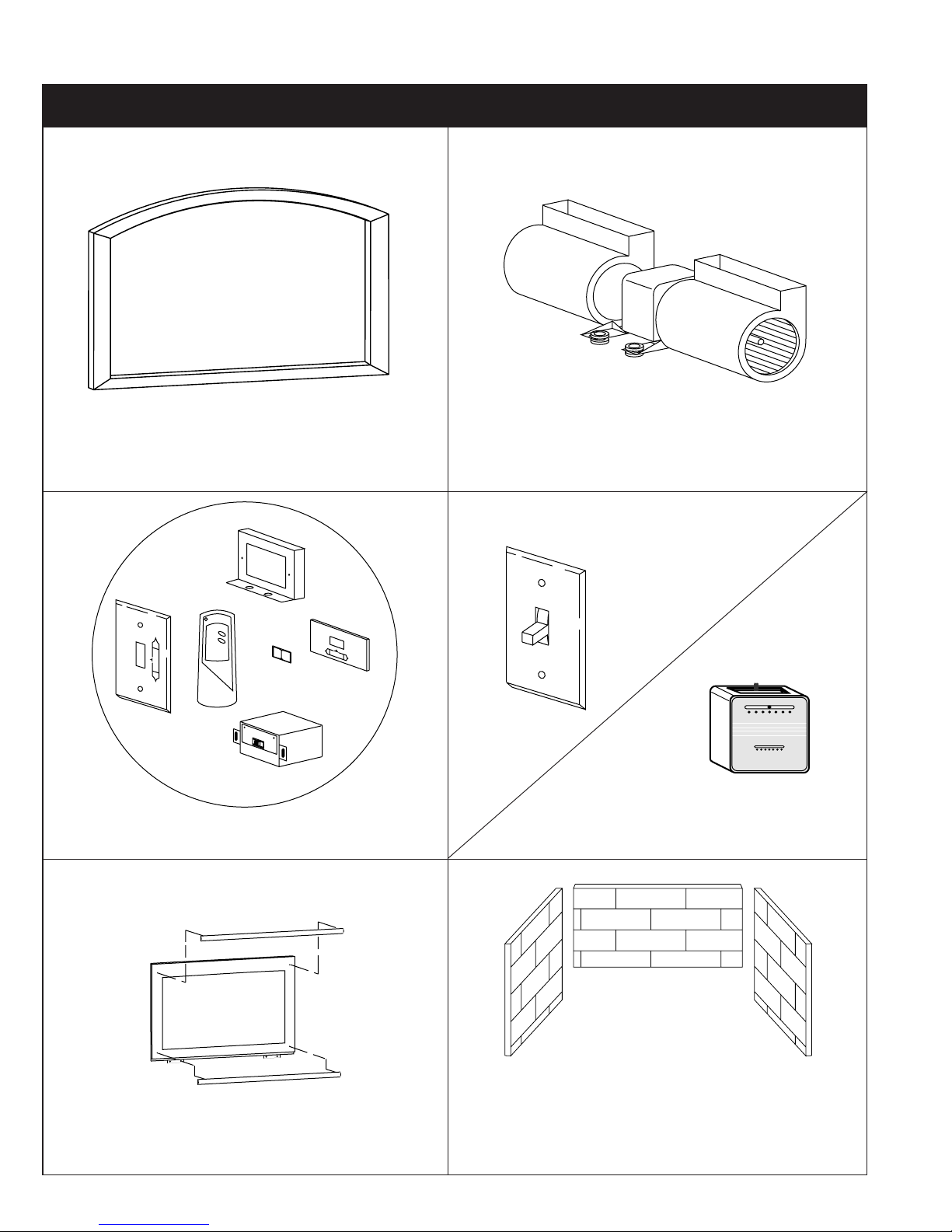
OPTIONAL KITS AVAILABLE
MODEL: BDK60
BRASS DOOR TRIM KIT
SKYTECH
NO
R
E
M
O
T
E
OFF
INDICATOR
ON
OFF
SKYTECH
1001
MODEL: RCK60
REMOTE CONTROL KIT
SKYTECH
MODEL: B60
BLOWER KIT
MODEL: WSK60
WALL SWITCH KIT
REMOTE
2110 32 c
50
60 70 80 90
2110 32 c
50
60 7080 90
MODEL: WTK60
WALL THERMOSTAT KIT
MODEL: FVK60
FULL-VIEW DOOR KIT
22
REFRACTORY CERAMIC BRICK KIT
NOTE: DIAGRAMS & ILLUSTRATIONS NOT TO SCALE
MODEL: CBK60
USSC
Page 23
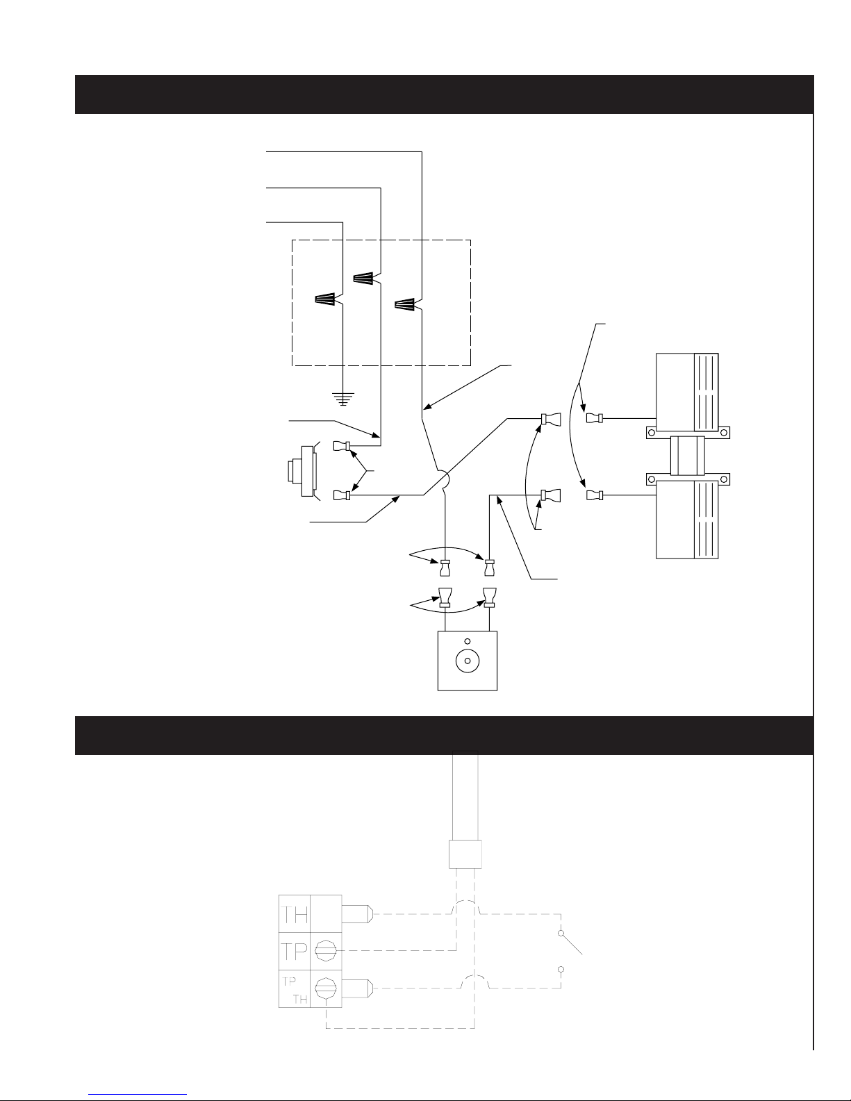
WIRING DIAGRAM FOR OPTIONAL (MODEL #B60) BLOWER KIT
WHITE
(Neutral)
BLACK
(Hot)
GREEN
(Ground)
2x4
BOX
1/4" MALE INS.
ATTACH GROUND
TO SIDE OF UNIT
WITH SCREW INCLUDED
80377
THERMO
DISC
80378
1/4" FEMALE INS.
1/4" MALE INS.
WIRING DIAGRAM FOR GENERATOR ASSEMBLY
GREEN
RHEOSTAT
BLACK
1/4"
FEMALE
INS.
BLACK
WHITE
80377
WHITE
1/4" MALE INS.
BLOWER
80378
TERMINALS
USSC 23
THERMOPILE
CONTROL
WIRING
ROCKER
SWITCH
NOTE: DIAGRAMS & ILLUSTRATIONS NOT TO SCALE
Page 24

WIRING GUIDE FOR 9660
The following Wiring Guide is to help assist in the wiring of any combination of the Optional Kit listed below:
RCK60 - REMOTE CONTROL KIT
WSK60 - WALL SWITCH KIT
WTK60 - WALL THERMOSTAT KIT
IMPORTANT: Before ordering or installing any to the available kits, remember the following...
1) Not all Optional Kits will work together. Example: The (RCK60) Remote Control Kit,
the (WSK60) Wall Switch Kit, and the (WTK60) Wall Thermostat Kit cannot be used at the
time.
2) When using any of the three Optional Kits listed above, the Rocker Switch on the unit
must be set to "OFF".
3) If you choose to use any combination of the above Optional Kits, only one of those kits
can be used at a time. Example: If you have the Optional Remote Control Kit and the Optional
Wall Switch Kit, operation of the unit must be controlled by one or the other. If you want to
use the remote control, simply turn the Wall Switch to "OFF".
STANDARD WIRING FROM FACTORY:
CONTROL VALVE
O
L
T
I
P
O
L
I
T
P
O
F
F
N
O
S
it
TP TH
E
A
TP TH
ROCKER
SWITCH
WIRING OF THE RCK60 - REMOTE CONTROL KIT:
CONTROL VALVE
O
L
I
T
P
O
F
F
N
O
S
it
E
A
WIRING WITH THE WTK60 - WALL THERMOSTAT KIT:
CONTROL VALVE
O
L
I
T
P
O
F
F
N
O
S
it
E
A
24
O
L
T
I
P
TP TH
TP TH
PIGGYBACK
DISCONNECT
WALL
THERMOSTAT
O
L
T
I
P
TP TH
TP TH
PIGGYBACK
DISCONNECT
NOTE: DIAGRAMS & ILLUSTRATIONS NOT TO SCALE
REMOTE CONTROL
SENSOR
ROCKER
SWITCH
2110 32 c
50
60 70 80 90
2110 32 c
50
60 7080 90
ROCKER
SWITCH
Remember the Rocker
Switch must be turned
to "OFF" while using
the Remote Control.
Remember the Rocker
Switch must be turned
to "OFF" while using
the Wall Thermostat.
USSC
Page 25
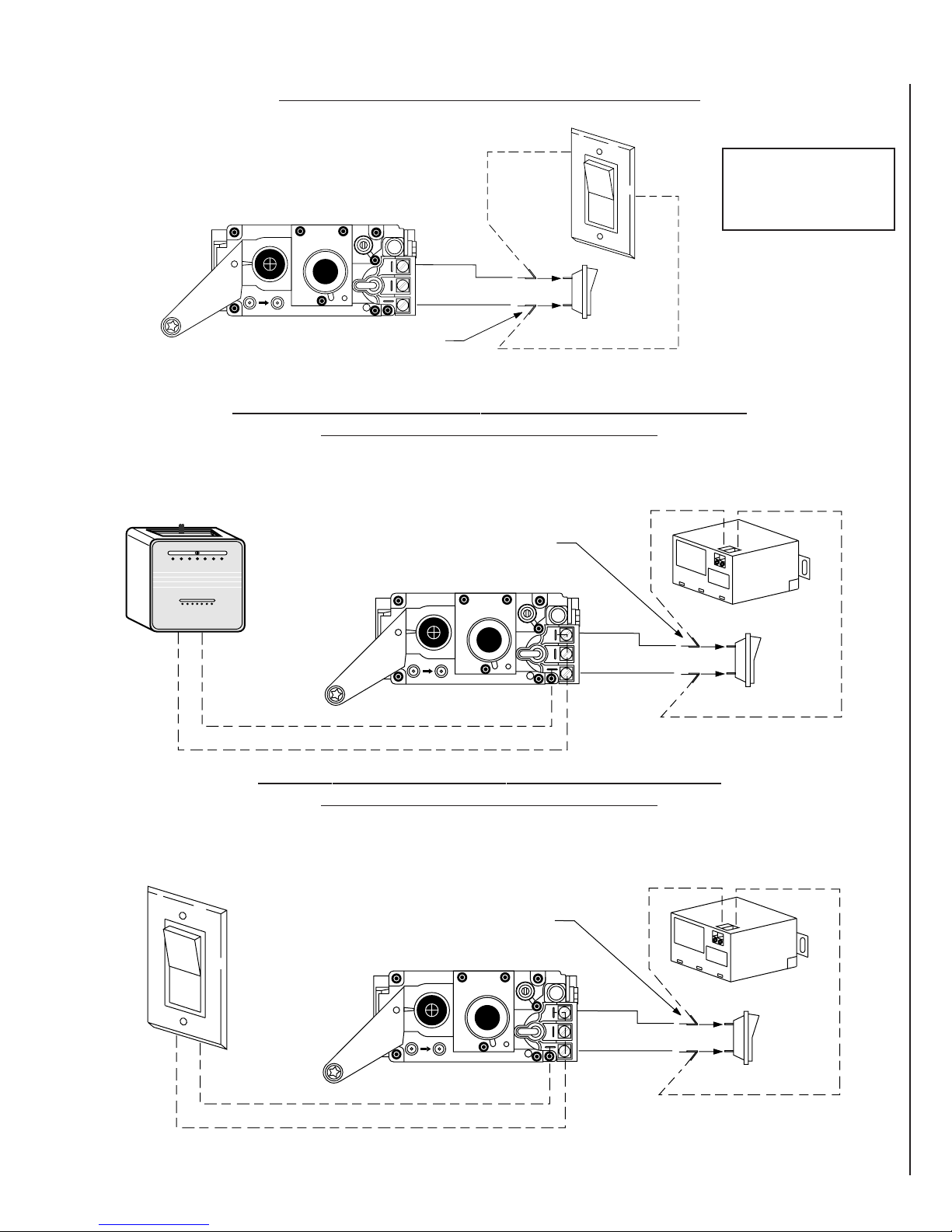
WIRING WITH THE WSK60 - WALL SWITCH KIT:
Remember the Rocker
Switch must be turned
to "OFF" while using
the Wall Switch.
CONTROL VALVE
O
L
I
P
O
L
I
T
P
O
F
F
N
O
S
it
E
A
T
PIGGYBACK
DISCONNECT
TP TH
TP TH
WALL
SWITCH
ROCKER
SWITCH
WIRING WITH THE WTK60 - WALL THERMOSTAT KIT AND
THE RCK60 - REMOTE CONTROL KIT:
Note: When combining these Optional kits, only one kit can be used at a time. Example: If you want to control the
operation of this unit with the Remote Control then you must turn the Wall Thermostat "OFF". When trying to use two
Optional kits at once, one will always override the other.
PIGGYBACK
DISCONNECT
O
L
T
I
P
TP TH
TP TH
REMOTE CONTROL
SENSOR
ROCKER
SWITCH
50
60 70 80 90
50
2110 32 c
2110 32 c
60 70 80 90
WALL
THERMOSTAT
CONTROL VALVE
O
L
I
T
P
F
O
F
N
O
S
it
E
A
WIRING WITH THE WSK60 - WALL SWITCH KIT AND
THE RCK60 - REMOTE CONTROL KIT:
Note: When combining these Optional kits you must remember that only one of them can be used at a time. Example:
If you want to control the operation of this unit with the Remote Control then you must turn the W all Switch "OFF". When
trying to use two Optional kits at once, one will always override the other.
PIGGYBACK
DISCONNECT
WALL
SWITCH
CONTROL VALVE
O
L
I
P
O
L
I
T
P
F
O
F
N
O
S
it
E
A
T
TP TH
TP TH
REMOTE CONTROL
SENSOR
ROCKER
SWITCH
For further information, contact our Customer Service Department at United States Stove Compan y, 227 Industrial Park
Road, P.O. Box 151, South Pittsburg, Tn. 37380. (423)837-2100
USSC 25
NOTE: DIAGRAMS & ILLUSTRATIONS NOT TO SCALE
Page 26

NOTES
26
NOTE: DIAGRAMS & ILLUSTRATIONS NOT TO SCALE
USSC
Page 27
NOTES
USSC 27
NOTE: DIAGRAMS & ILLUSTRATIONS NOT TO SCALE
Page 28

HOW TO ORDER REPAIR PARTS
THIS MANUAL WILL HELP YOU OBTAIN EFFICIENT, DEPENDABLE SERVICE
FROM YOUR 9660 GRAVITY TYPE VENTED WALL FURNACE, AND ENABLE YOU
TO ORDER REPAIR PARTS CORRECTLY.
KEEP THIS MANUAL IN A SAFE PLACE FOR FUTURE REFERENCE.
WHEN WRITING, ALWAYS GIVE THE FULL MODEL NUMBER WHICH IS ON THE
NAMEPLATE ATTACHED TO THE HEATER.
WHEN ORDERING REPAIR PARTS, ALWAYS GIVE THE FOLLOWING
INFORMATION AS SHOWN IN THIS LIST:
T
I
N
U
U
E
D
S
C
O
S
T
M
A
1. THE PART NUMBER
2. THE PART DESCRIPTION
3. THE MODEL NUMBER: 9660
4. THE SERIAL NUMBER: ____________________
T
E
S
S
T
S
N
A
P
C
Y
O
V
E
UNITED STATES STOVE COMPANY
227 INDUSTRIAL PARK ROAD
PO BOX 151
SOUTH PITTSBURG, TN 37380
(423) 837-2100
A
A
S
C
S
E
D
R
E
M
GS
A
S
O
C
E
R
T
G
I
N
C
I
A
N
R
N
O
I
T
A
I
D
E
I
F
I
28
NOTE: DIAGRAMS & ILLUSTRATIONS NOT TO SCALE
USSC
 Loading...