

Page 1

ENTERPRISE NETWORK HUB SYSTEM
NETServer/8
NETServer/8
NETServer/16
NETServer/16
TM
Command Reference
Version
3.1
Page 2

Copyright 1996 by U.S. Robotics Access Corp.
8100 North McCormick Blvd.
Skokie, Illinois 60076
All Rights Reserved
U.S. Robotics and the U.S. Robotics logo are register ed trademarks of
U.S. Robotics Access Corp., Total Control is a trademark of U.S.
Robotics Access Corp. Any trademarks, tradenames, service marks or
service names owned or registered by any other company and used in
this manual are the property of their respective companies.
ii
Page 3

Table of Contents
Warranty and Service
Chapter 1 Overview
What’s New in 3.1? 1-1
NETServer Overview 1-5
Chapter 2 Basic Installation
System Administrator Requirements 2-1
Accessing the Command Line 2-3
Getting Started 2-4
Getting the LAN Port Up and Running 2-5
Recommended Global Configuration 2-11
Chapter 3 Configuration Overview
How to Set Up Applications 3-1
The Command Line 3-3
Quick Command Overview 3-5
Overview of Configurable Tables 3-6
Chapter 4 IP Terminal Server Setup
Terminal/Workstation Setup 4-1
NETServer Setup (Overview) 4-2
Using Default Hosts 4-3
IP Terminal Server (Detailed Setup) 4-4
Configuring a port 4-4
Adding a Login User to the User Table 4-9
IP Terminal Server Case Studies 4-12
iii
Page 4

Chapter 5 Network Dial-in Access
Dial-In User Setup 5-1
NETServer Dial-In Setup (Overview) 5-2
NETServer Dial-In (Detailed Setup) 5-4
Configuring a Port 5-4
Adding a Network User to the User Table 5-6
IP Remote Access Case Study 5-11
IPX Remote Access Case Study 5-15
Chapter 6 LAN-to-LAN Routing
Setup for NETServer Routing (Overview) 6-1
An Introduction to NETServer Routing 6-4
PAP and CHAP Authentication 6-9
LAN-to-LAN Routing (Detailed Setup) 6-12
Configuring a Port 6-12
Adding a Remote Device to the Location Table 6-14
Adding a Remote Device to the User Table 6-22
LAN-to-LAN Routing Case Study 6-25
Testing the Connection 6-29
Chapter 7 Talking to the Modems
TCP/IP Modem Sharing 7-1
Implementing Security with Host Device Dial Out 7-3
Configuring Modems as UNIX pseudo TTYs 7-4
Modem Initialization Scripts 7-6
Sending A T Commands 7-9
Chapter 8 Packet Filters
Packet Filter Overview 8-1
Adding Packet Fitlers 8-4
Filter Rule Format 8-6
TCP/IP Rules 8-8
TCP and UDP parameters 8-10
Filtering ICMP packets 8-15
IPX Packet Filtering 8-16
SAP Rules 8-18
Editing Packet Filters 8-19
iv
Page 5

Chapter 9 Administrative Tools
Configuring the !root Account 9-1
Manually Connecting to a Remote Site 9-3
T r oubleshooting Commands 9-4
The SHOW commmand 9-11
Chapter 10 Command Reference
Global Configuration 10-1
Hosts Table Configuration 10-13
Location Table 10-14
LAN Port (Net0) Configuration 10-24
Netmasks Table Configuration 10-30
Ports Table (S-port configuration) 10-31
Routes Table Configuration 10-49
SNMP Table 10-54
User Table 10-57
Reference Section
Appendix A Technical Specifications
Appendix B Addressing Schemes
Appendix C Software Download
Appendix D The Boot Process
Appendix E Syslog Accounting
Appendix F RADIUS Security and Accounting
Index
v
Page 6

Limited Warranty
U.S. Robotics Access Corp. warrants to the original consumer or
other end user purchaser that all U.S. Robotics Total Control
products and parts are free from defects in materials or workmanship for a period of two years from the date of purchase.
During the warranty period, and upon proof of purchase, the
product will be repaired or replaced (with the same or similar
model) at our option, without charge for either parts or labor.
This warranty shall not apply if the product is modified, tampered with, misused, or subjected to abnormal working conditions.
Warranty and Service
REPAIR OR REPLACEMENT AS PROVIDED UNDER THIS
WARRANTY IS THE EXCLUSIVE REMEDY OF THE PURCHASER. THIS WARRANTY IS IN LIEU OF ALL OTHER
WARRANTIES, EXPRESS OR IMPLIED, INCLUDING ANY
IMPLIED WARRANTY OF MERCHANTABILITY OR FITNESS
FOR A PARTICULAR USE OR PURPOSE, AND U.S. ROBOTICS
SHALL IN NO EVENT BE LIABLE TO PURCHASER FOR
INDIRECT OR CONSEQUENTIAL DAMAGES OF ANY KIND
OR CHARACTER.
Some states do not allow the exclusion or limitation of incidental
or consequential damages or allow limitations on how long an
implied warranty lasts, so the above limitations or exclusions
may not apply to you. This warranty gives you specific legal
rights, and you may also have other rights which vary from
state to state.
vi
Page 7

Service and Support
To obtain service, contact the U.S. Robotics Systems Product
Support Department as described below. Whichever method
you use to contact us, please have the product serial number(s)
available.
Technical Support
For technical assistance, contact USR in one of the following
ways:
Mail 8100 North McCormick Blvd.
E-Mail support@usr.com
Toll-Free Line 800-550-7800
Fax 847-982-0823
BBS 847-982-5092
Skokie, Illinois 60076-2999
Fax on Demand 800-762-6163
America Online Keyword USROBOTICS
CompuServe GO USROBOTICS
Anonymous FTP ftp.usr .com* Username=Anonymous
Password=your internet address.
World Wide Web http://www .usr.com
*The FTP is for downloading files only.
If the support representative determines that you should send
your equipment to USR for service, you will be given a Service
Repair Order (SRO) number to help track your service request.
Once you have received an SRO number, take or mail the
product, postage pr epaid, to U.S. Robotics at the above address.
Include proof of the date of purchase.
IMPORTANT: If you ship your unit, pack it securely, be sure
your SRO number is visible on the outside of the package, and
ship it charges prepaid and insured.
vii
Page 8

We welcome your suggestions for better documentation
Every effort has been made to provide useful, accurate information. If you have any comments or suggestions, please let us
know.
By voicemail: (708) 933-5200
Via the Internet: sysdocs@usr.com
viii
Page 9

This chapter provides an overview of the Total Control
NETServer/8 and NETServer/16. It also contains information
on what’s new in version 3.1 of the NETServer firmware.
What’s New with Release 3.1?
Release 3.1 supports the following new features:
• Classless InterDomain Routing and Host-based routing via
the Netmask Table.
Chapter 1
Overview
• IP address spoofing.
• Support for RADIUS accounting servers, ANI/DNIS, and
ICMP message logging.
• Support for a secondary and a tertiary name server.
• Randomized use of Default/Alternate Hosts for load
balancing.
• New Modem Port Features
Additional Software Enhancements
• NetBIOS over IPX support
• PAP enable/disable
• Pre-allocated system netbufs increased from 1000 to 1400
• Rezero network statistics and session statistics saved until
next call
• Unidirectional Van Jacobson compression
• Users set to Prompt may specify a TCP port with the host
name or IP address when using Telnet
Overview 1-1
Page 10

Netmask T able
CIDR (Classless Interdomain Routing) or host-based routing
requires special netmasks. Special netmasks may also be useful
for debugging.
The Netmask Table allows you to configure netmasks for CIDR
or host-based routing as needed. RIP messaging/dynamic route
information must be active for host-based routing.
IP Address Spoofing
The NETServer may now be configured to spoof a single IP
address. When the NETServer identifies itself to remote routers
or other remote devices, it uses this IP address rather than the IP
address of its LAN interface.
IP address spoofing is useful when more than one NETServer
must appear to be a single router or other device to remote
networks and other routers.
Accounting Servers
The NETServer supports the following new features:
• Log accounting information to a RADIUS accounting server
such as the security feature of U.S. Robotics Total Control
Manager.
• ANI and DNIS call information
• Log ICMP error messages to a UNIX Syslog server
Accounting Server Support
The NETServer now supports event logging. You can configure
the NETServer to send event information to a Total Control
Accounting Server or a UNIX accounting server. You can also
configure the NETServer to send the event information to an
alternate accounting server if the primary server is unavailable.
Event logging is performed by transmitting a record containing
event information from the NETServer client to an accounting
server. TCM uses the RADIUS client/server model for this
feature.
1-2 Overview
Page 11

RADIUS Accounting and ANI/DNIS
Release 3.1 of the NETServer supports the current RADIUS
Accounting Internet Draft. The NETServer can generate
appropriate Code 4 Accounting-Request and Code 5
Accounting-Response messages for properly configure d
RADIUS servers.
The NETServer’s RADIUS implementation also supports ANI
and DNIS services.
ICMP Message Logging
If your system uses syslog network accounting, you can
configure the NETServer to send ICMP error messages to the
syslog server.
Multiple Name Servers
Release 3.1 of the NETServer supports up to two name servers.
The first is a primary name server, and the second is a backup
server that is used when the primary name server is
unavailable.
Note: The NETServer does not support more than one name
service at a time (DNS and NIS cannot both be running).
Randomized Hosts
You can now relieve the burden on frequently-used global
default, port default and RADIUS user table hosts, by
randomizing the selection of the host chosen for user sessions.
When this feature is enabled, a preferred host will be randomly
chosen from among the default and alternate hosts defined
rather than always preferring the default host.
Overview 1-3
Page 12

New Modem Port Features
Release 3.1 of the NETServer Command Line and NETServer
Manager software now support the following modem port
features:
• Download new firmware to the modems using NETServer
Manager (windows software) version 3.2 or later.
• You can now send AT commands directly to the modems
from the NETServer’s command line.
• Detect and flush of stopped ports
• Dialback delay
• Port status display shows current and configured status
• Ports reset if Carrier Detect is lost before a user connects to a
host
• Support for of up to eight Alternate Hosts
1-4 Overview
Page 13

NETServer Overview
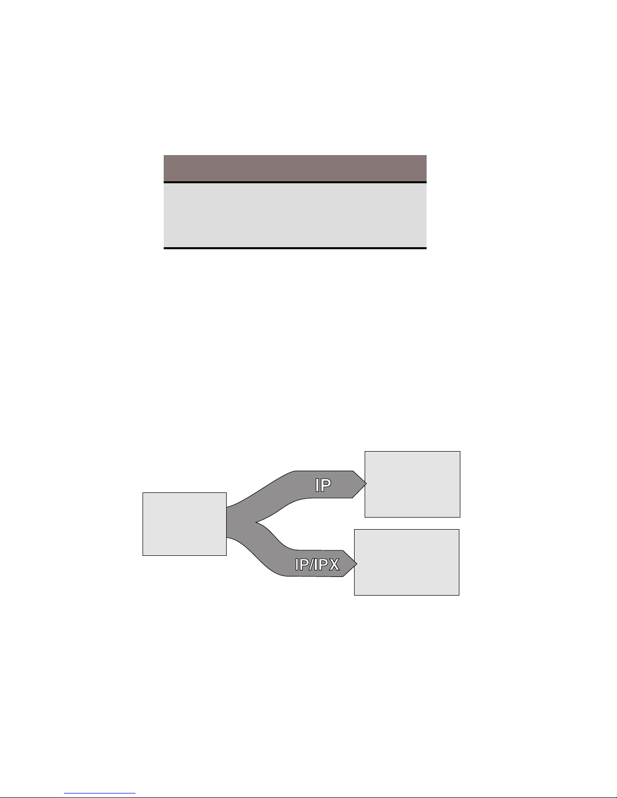
The NETServer allows you to implement four basic applications:
IP Terminal Service, IP modem sharing, IP/IPX Network Dial In,
and IP/IPX LAN-to-LAN routing. Everything else it does is
based on one of these four.
IP T erminal Service
Remote terminals can log into an IP host on the NETServer’s
local network as of they were physically connected to it. To do
this, the NETServer receives TTY terminal output (keystrokes)
over a dial up line. It then forwards the terminal output to the
host using a virtual terminal protocol (login service) like Telnet
or Rlogin. Since the connection is bi-directional, the terminal
also receives the host’s responses.
Overview 1-5
Page 14

IP Modem Sharing
Hosts on a local IP network can use a chassis modem to dial out.
Moreover, the NETServer can create pools of modems that can
be used by local hosts on a first come, first serve basis.
To do this, the NETServer allows the host to establish a virtual
terminal session with the modem. The host can then interact
with the modem’s command line and from there, dial out.
On a UNIX host, you can install a pseudo TTY driver that allows
the host to interact with this virtual terminal connection as if it
was actually a serial port. This makes the modem appear to be
directly connected to the host.
Network Dial In Access
Remote IP and IPX users can dial in and attach to the local
network as if they were local nodes. IP and/or IPX packets are
transmitted over a dial in connection encapsulated in a serial
line networking protocol (PPP or SLIP). When received by the
NETServer, the IP and IPX packets are forwarded from the
remote user to the LAN and vice versa.
1-6 Overview
Page 15

Dial-Up Routing
The same routing engine that allows network dial in access
allows the NETServer to establish dial up routing sessions with
remote networks. Such connections can be maintained
continuously or established on an on-demand basis and torn
down when not needed.
How do I get there from here?
Configuring any of these applications on a NETServer is a threestep process:
1.
Perform basic configuration for the NETServer. This
includes configuring it to talk to your LAN and setting
global user and global routing parameters. You can begin
this process by going to Chapter 2.
2. Configure modem “S-ports” to support the application
3.
Configure user table entries for dial in connections and IP
modem sharing, location table entries for dial out routing.
Steps 2 and 3 are covered by application in chapters 4 through 7.
Overview 1-7
Page 16

Security
The NETServer supports IP and IPX packet filtering in both the
inbound and the outbound directions of ports, users, and dial
out locations. Packet filter configuration is discussed in Chapter
8.
The NETServer also supports the use of a centralized RADIUS
security server, allowing you to create a single account for each
user rather than multiple user accounts on multiple NETServers.
RADIUS security is discussed in Appendix F.
Administrative Utilities
The NETServer’s command line includes an assortment of
utilities for troubleshooting connections including:
• The ability to manually dial a location to test connectivity
• The ability to use Telnet, Rlogin or PortMux to establish a
session with another host from the NETServer’s command
line.
• UNIX-like troubleshooting commands including ifconfig,
ptrace, ping and tracer oute for debugging IP connections.
These commands are contained in Chapter 9, along with
instructions for customizing the supervisor account.
1-8 Overview
Page 17

Chapter 2
Basic Installation
This chapter contains information on the following:
• System Administrator Requirements
• Logging into the supervisor account for the first time
• Getting the LAN port up and running
• Recommended Additional Configuration
System Administrator Requirements
In compiling this manual, we have had to make certain assumptions about the knowledge of users who will install the product.
The documentation assumes that the system administrator is
familiar with Novell networks and/or IP networks, as well as
networks in general. Novell offers a variety of programs to
certify administrators in network technology. TCP/IP information is available from a variety of sources, some of which are
covered below.
After reviewing this manual, users should decide if their ability
is sufficient to handle the technical details of installation. If the
assistance of a qualified professional is needed, we recommend
that you consult with your nearest authorized U.S. Robotics
Platinum reseller for advice. For a service fee, U.S. Robotics also
offers qualified engineering assistance on site. Contact Systems
Product Support at (800) 231-8770 for more information.
Basic Installation 2-1
Page 18

TCP/IP Reference Material
It is the responsibility of the Network Manager to devise an
addressing strategy appropriate for the size and growth potential of the network. We recommend the following reference
material for TCP/IP:
Comer, D.E., Internetworking with TCP/IP Volume I:
Principles, Protocols and Architecture, Prentice-Hall,
Englewood Cliffs, New Jersey, 1995.
IP machines and networks that will be attached to the Internet
must obtain registered addresses from the Internet’s Network
Information Center. They can be contacted at the following
address and phone number.
Network Solutions
InterNIC Registration Services
505 Huntmar Park Drive
Herndon, VA 22070
1-703-742-4777
However, for networks with only a few IP machines, it is
probably better to contact your local Internet access provider
and let them handle the details.
2-2 Basic Installation
Page 19

Accessing the Command Line
To configure the NETServer fr om the command line, you must
log in as the supervisor.
1. In order to login, you need a login prompt. There are three
ways to get one:
• Attach the provided serial cable to the CONSOLE port
and attach the other end of the cable to a terminal (or a
PC running terminal emulation software such as Windows Terminal). See the Quick Start Guide for more
information.
• Using communications software, dial into any modem
port that is configured to support user login or network
dial in (by default, they all are). The data format is 8
data bits, 1 stop bit and no parity (8-N-1).
• If you have configured the LAN port (Ethernet interface)
to communicate with a local TCP/IP network, you can
Telnet to the NETServer using the address assigned to
this port. For information on configuring the LAN port,
see Getting the LAN Port Up and Running, later in this
chapter.
Note that if you are just turning the NETServer on, it may take a
few seconds after the NETServer begins to boot before the login
prompt appears. If the login prompt does not appear, try
hitting the Enter key.
2. Login as the supervisor/superuser by typing the following:
!root
(Must be all lower case!)
Enter
3. The password prompt appears. The default is no password
at all. If you have changed the password for the !root
account, type the new password in and press the Enter key.
Otherwise, just press
Enter
4. The “Command>” prompt appears. The NETServer is now
ready to be configured.
Basic Installation 2-3
Page 20

Getting Started
Name your NETServer. Among other things, this name will be
used for the NETServer’s DNS system name and its SNMP
system name. It is also the name that the NETServer will
advertise in SAP broadcasts. No other device on your network
should be using this name. Use the following command:
set sysname <name (up to 32 characters)>
Enter
The next thing you need to do is get your NETServer talking to
the network attached to its LAN port. This section below titled
Getting the LAN port up and running contains the minimum
configuration needed to allow the NETServer to talk to your
Ethernet or Token Ring LAN. Keep in mind that these may not
be the only parameters you’ll want or need to set—just the ones
you must set. A complete listing of LAN port parameters can be
found in Chapter 10.
Once you have configured the NIC interfaces, we recommend
that you proceed to global configuration. The parts of this that
most administrators will want to do right away can be found
later in this chapter under Recommended Global Configuration. A
more complete listing of global parameters can be found in
Chapter 10.
2-4 Basic Installation
Page 21

Getting the LAN port up and running
First step for IPX or IP/IPX networks
If your network uses the IPX protocol, you must enter the IPX
network number of the segment the NETServer connected to the
NETServer’s LAN port. You can find this network number
using Novell’s CONFIG utility.
For File Servers Running Novell Version 3.xx
1. Go to the console of a file server that is on the same network
segment that the NETServer is on.
2. From Novell’s Console program press CTRL-ESC, then ESC,
until the : (colon) prompt appears. Select System Console
and press the Enter key.
3. Type the following:
CONFIG
Enter
A display similar to the one shown below appears:
File server name: USR_SERVER_ONE
IPX internal network number: 0000000A
Western Digital Star EtherCard PLUS Driver v2.05 (910424)
Hardware setting: I/O Port 300h to 31Fh, Memory CC000h to
Cffffh, Interrupt Ah
Node address: 0000C0488D28
Frame type: ETHERNET_802.3
Board name: TENBASE_802.3
LAN protocol: IPX network 00000255
Western Digital Star EtherCard PLUS Driver v2.05 (910424)
Hardware setting: I/O Port 300h to 31Fh, Memory CC000h to
Cffffh, Interrupt Ah
Node address: 0000C0488D28
Frame type: ETHERNET_802.2
Board name: TENBASE_802.2
LAN protocol: RPL
LAN protocol: IPX network 00000684
Basic Installation 2-5
Page 22

This is an example of the information returned for one
version 3.xx card that has two different frame types. The
card has one port address, but two LAN protocol network
addresses, one for each frame type. The network number
for 802.3 is 00000255, and for 802.2 it is 00000684.
4. Write down the LAN protocol IPX network number for the
frame type you want to use.
For File Servers Running Novell Version 2.xx
1. Go to the console of a file server that is on the same network
segment that the NETServer is on.
2. Press CTRL-ESC until the : (colon) prompt appears.
3. Type the following:
CONFIG
Enter
A display similar to the one shown below appears:
LAN A Configuration Information:
Network Address: [0788] [002608C0D53F4z]
Hardware T ype: [3Com 3C505 EtherLink Plus (Assy 2012 only)
V2.30EC (880813)]
Hardware Setting: IRQ=5, IO=300h, DMA 5
The above example only has one frame type, so the network
address is 0788.
4. Write down the network address for the frame type you
want to use.
2-6 Basic Installation
Page 23

IP Configuration
Enter
1.
IP Network Address: You must assign an IP address to the
NETServer’s LAN interface (Ethernet or Token Ring port).
Type the following:
set net0 address <IP address>
Enter
If your network does not use IP, you may choose whatever
address you like. See Appendix B for some basics on TCP/
IP addressing. However, if you want to connect the
NETServer to the Internet (even indirectly), the address
must be unique in the world. To obtain such an address,
contact your local Internet service provider. If you need a
large number of IP addresses, you may want to contact the
InterNIC (see the beginning of this chapter for their address).
Example:
set net0 address 192.77.203.200
2. You must set the LAN port’s subnet mask. The default is
255.255.255.0, which would be appropriate for a Class C
network with no subnetting or for Class C size subnets of
larger networks. You must change this value if the network
attached to the NETServer’s LAN port uses a different
subnet mask. To change the Netmask, type the following:
Example:
set net0 netmask <netmask>
set net0 netmask 255.255.255.0
Enter
Enter
Basic Installation 2-7
Page 24

3. You must also set the Broadcast Address. Type the
following:
set net0 broadcast <
high
or
low
>
Enter
High The bits of the host portion of a broadcast address
are all ones. This is the rule for the vast majority of
IP networks.
Low The bits of the host portion of a broadcast address
are all zeroes. This is rare, but is still used by
some systems including Sun OS 4.x (Solaris 1.x).
For example, the node 192.77.203.7 uses the default subnet
mask of 255.255.255.0, which would give it a high broadcast
address of 192.77.203.255 and a low broadcast address of
192.77.203.0. To use the address ending in 255:
set net0 broadcast high
Enter
4. If your network does not use the IPX protocol, you may now
go to Final Steps. Otherwise complete the steps in the next
section, IPX Configuration.
2-8 Basic Installation
Page 25

IPX Configuration
IMPORTANT: Even if your network uses only the IPX protocol,
you must set up an IP address for the NETServer if you want to
use the Windows-based management software. If you have not
already done so, perform step 1 under IP Configuration.
1. IPX Network Frame Type: This is the IPX frame type of the
network segment connected to the NETServer’s LAN port.
set net0 ipxframe <frame type>
Enter
Valid frame types are:
ethernet_802.3
ethernet_802.2
ethernet_802.2_II
ethernet_II
Example:
set net0 ipxframe ethernet_II
Enter
2. IPX Network Number: This is the network number of the
network segment connected to the NETServer’s LAN port.
Note that the same physical network segment will have a
different network number for each frame type used. Be sure
to select the network number associated with the frame type
selected above. Type the following:
set net0 ipxnet <network number>
Enter
<Network Number> is the number you obtained by following the instructions titled First Step for IPX Networks. If you
have not already obtained this number, do so now.
Example:
Note that the preceding 0’s in this example could have been
omitted. The NETServer would have accepted “684” as the
correct IPX Network Number and filled in the preceding 0’s.
set net0 ipxnet 00000684
Enter
Basic Installation 2-9
Page 26

Final Steps
Save your configuration and reboot the NETServer. Note that
the LAN port settings are the only configuration changes that
will require rebooting the NETServer.
To save your changes, type the following:
save all
Enter
Wait until the RN/FL LED is green. Rebooting the NETServer
while a save is in progress could cause the flash memory to be
corrupted. When the LED is green, type the following:
reboot
Enter
Note that the NETServer may respond with a command prompt
to indicate that it has received the reboot command, but you will
not be able to access the NETServer until it finishes rebooting.
When the NETServer finishes rebooting, the login prompt will
reappear.
From this point on, configuration can also be done fr om the
Windows-based NETServer Manager software. If you would
rather configure the NETServer from Windows, proceed to the
Installation and Recommended Configuration sections of the
NETServer Windows Software Guide.
2-10 Basic Installation
Page 27

Recommended Global Configuration
Following is a list of global fields that we recommend you
configure.
Password
This is the password for the superuser (supervisor) account. If a
password has been set, it must be entered when logging into the
NETServer from either the command line or from the Windowsbased software. The default is none. The password can be any
combination of up to 15 ASCII characters. Type the following:
set password <password>
Enter
Do not forget your password. If you do you will have to erase
all configuration information saved in flash memory - set DIP
switch #4 in the bottom row of DIP switches ON (down) and
reboot the NETServer. If you do not have your NETServer’s
configuration saved to disk (using the NETServer Windows
software), you will have to start all over again.
IP and IPX Default Gateways
If the NETServer does not know where to send a packet, it
forwards the packet to the default gateway or router defined in
this step. Default gateways must be on the same subnet as the
NETServer.
You must also enter a metric (hop count) for each type of default
gateway. Possible values range from 1 (default) to 15. Note that
since the actual metric of a default gateway is only 1 hop, the
value entered here is used to control the perceived cost of the
gateway to other routers on your network. For example, a high
metric will limit the number of hops that the route is broadcast
and may cause other routers to see it as a less preferable route.
If the NETServer is configured to listen for IP default route
broadcasts (see Global Configuration, Default Route in Chapter 10),
the IP Default Gateway can be overridden by a default route
broadcast with a lower hop count.
Basic Installation 2-11
Page 28

To set the IP gateway, type the following:
set gateway <IP address> <metric>
Enter
The following example configures an IP default gateway whose
cost is prohibitive to all but the closest subnets:
set gateway 192.77.203.200 12
Enter
To set the IPX gateway, type the following:
set ipxgateway <IPX node address> <metric>
Enter
The IPX node address is the full hex IPX node address, in other
words:
8 digit network number:12 digit node MAC address
The following example sets up a default gateway on network
number A34. Note that the preceding zeros could be omitted:
set ipxgateway 00000A34:000000123456 1
2-12 Basic Installation
Page 29

Name Service
This is the server that translates your host names into their
corresponding IP addresses.. The NETServer supports two
types of name servicesDNS and NIS. NIS is also sometimes
referred to as Yellow Pages (YP).
If you are using DNS, type
set namesvc DNS
Enter
If you are using NIS, type
set namesvc NIS
Enter
You must also identify the name server and domain name used
by the name service. The name server (the computer responding to name service queries) is indicated by its IP address. The
domain name is the domain that the NETServer belongs to.
Type the following lines. Follow each with the Enter key.
set nameserver <IP address>
set domain <domain name>
Note: The name server will only be consulted to resolve host
names not found in the hosts table. If you are using a name
service, the hosts table may be left empty.
Save your work
Once you are done setting the desired parameters, you can save
your changes to flash memory by typing the following:
save all
Enter
Basic Installation 2-13
Page 30

2-14 Basic Installation
Page 31

Configuration Overview
The internal firmware lets you manage and configure the
NETServer by typing commands. This chapter covers the
following:
• How to set up applications
• Issuing commands
• Quick Command Overview
• Overview of configurable tables
How to Setup Applications
Chapter 3
There are three applications the NETServer is designed to
handle: user dial in access, modem sharing, and LAN-to-LAN
routing. All other applications are variations on one of these.
Applications
User Dial In Access
Configuration for each of these applications is a two step
process:
- Each modem can be configured for one or more of these
IP Modem Sharing
LAN-to-LAN Routing
1. Configure one or more modems to support the application.
Note that modem ports may be configured to support
multiple applications at the same time.
2. Add user table or location table entries or both, depending
on the application.
Configuration Overview 3-1
Page 32
Where do I go from here?
Each of the three applications has a section of this manual
devoted to its setup. If you want to begin configuration
immediately, you may go to one of the chapters listed below:
Application Section
User Dial In Access Chapters 4 and 5
LAN-to-LAN Routing Chapter 6
IP Modem Sharing Chapter 7
Note that there are actually two Chapters for user dial in access.
They cover two very different types of user: login users and
network dial in users.
Login Users
These are users requesting terminal access to an IP host. They
dial into the NETServer and are connected to the requested host
with a login service such as Telnet or Rlogin. Note that these
users don’t need an IP address, since they aren’t actually
attaching to the network.
(See Chapter 4 for setup)
Login Users
Terminal-style login
using a service such
as Telnet or Rlogin
Dial In
Users
Network Dial In Users
These users actually pretend to be nodes, complete with addresses, on the network. They do this by using PPP or SLIP to
send network packets over the phone lines. Since all IPX users
attach to the network and have addresses, All IPX users are of
this type.
Network Dial In Users
Use PPP or SLIP to
become a virtual node
of the network
(See Chapter 5 for setup)
3-2 Configuration Overview
Page 33

The Command Line
The Command Line Interface is similar to DOS, UNIX or
Netware in that you can type commands to view information,
change settings and so on.
Commands are not case sensitive
You can type any command in upper or lowercase.
Table entries are case sensitive, however. For example,
“SASHA,” “Sasha” and “sasha” are three different users (or
locations).
You can abbreviate commands
You can abbreviate most commands and command options with
the first two or three letters that distinguish that command from
any other command. For example, you need only type set net0
addr to set the NETServer’s IP address (the full command is set
net0 address).
IMPORT ANT: Make sure that your abbreviation is long enough
to distinguish the command from any similarly spelled commands. For example, if you typed IPX to set the IPX network
number, you’ll get an error message. This is because you could
be referring to any one of the following commands: ipxnetwork,
ipxgateway, or ipxframe.
Separate a parameter and its value by a space
Do not use an equal sign ( = ) or any other punctuation mark
between a parameter and the value to be set. For example, you
should type the following:
set user fredb service netdata
You should not type the following:
set user fredb service=netdata
Enter
Enter
Configuration Overview 3-3
Page 34

Save your changes
You can save all of your changes, or you can save changes to a
specific table only.
Note: We recommend using save all. If you save tables
individually, the space used by the previous version of the table
is not freed up. Issuing the save all command frees up any
unused space before saving.
save all save all configuration data
save s<port #> save a port’s configuration
save filter save all of the packet filters
save global save the global table
save host save the hosts table
save ipxroute save the IPX routes table
save location save the location table
save netmask save the netmask table
save routes save the IP routes table
save snmp save SNMP configuration
save user save the User Table
Reset any ports you have changed
If you make changes to any port, you must reset the port before
the changes take effect. This will close any active connections on
the port!!!
reset all S-ports (s0 through s16)
reset s<port #> a specific S-port
reset n<connection handle> an active connection
(find handle with
show netconns
Reboot when necessary
The only changes that require rebooting the NETServer are
changing its LAN port (Net0) configuration. If you change the
Net0 configuration, save your work and then type the following
command:
reboot
How to log out of the command line
When you are done configuring the NETServer, you may exit
the command line interface by typing done, exit, or quit.
)
3-4 Configuration Overview
Page 35

Quick Command Overview
The NETServer’s configuration data is stored in several tables,
including the user table and the location table among others. To
change most parameters in these tables, use the set command:
set <user | location | port | etc.> <parameter name> <value>
For example:
set net0 address 192.77.203.5
set user John password Bumblebees
Some things, like individual locations and users, must be
created before they can be configured. The following command
is used:
add <user | location | filter | etc> <name>
Names are case sensitive!!! Note that anything that can be
added can also be deleted.
delete <user | location | filter | etc.> <name>
You can view current configuration information using the show
command. For example:
show net0
show user John
show ipxroutes
A complete listing of commands and options may be found in
the back of the Quick Start Guide. Help for any of these commands is available using the help command. For example:
help set
help set user
help add
help delete
help show
Configuration Overview 3-5
Page 36

Overview of configurable tables
This section contains a brief description of each of the
NETServer’s internal databases.
Global Configuration
The Global Configuration table lets you configure parameters
that apply to all ports, such as the Name Service (if any) your
network uses, default gateways through which to forward
packets, and so on. You can also set the Global Default Host that
login users may establish a session with, as well as the
NETServer’s password.
RADIUS Configuration
The Global Configuration table also allows you to designate a
RADIUS security server. A RADIUS security server will allow
you to maintain users in a single, centralized users file rather
than updating the users tables for several different NETServers
independently.
You may also specify a RADIUS network accounting server.
Hosts T able
The Hosts Table is a list of local hosts. The table is used to
translate names to IP addresses and vice versa. This allows
users and administrators to type host names rather than addresses.
This is especially useful if the network does not have a name
service such as NIS or DNS. If your network has a name server,
the NETServer tries to match the host name with an IP address
using the Hosts Table before using the name server.
Note that IPX networks do not use this table since SAP automatically provides the functionality of a name service.
3-6 Configuration Overview
Page 37

Initialization Script Configuration
A Port Initialization Script is a string of text that is sent to a
modem (or S0, the external serial port) each time the port is
reset (a modem resets itself every time it disconnects).
Initialization scripts for the modems will probably contain the
AT commands needed to configure them for use on your
network.
Location T able
The location table stores information about remote sites that the
NETServer needs to dial out to. The table is used during LANto-LAN routing, to tell the NETServer how to dial out to and
communicate with a remote location. It is also used for dialing
back network dial in users. Each location is configured with
parameters such as what addresses and which protocol to use
for the connection. A dial script for each location contains
instructions on how to dial out to and sometimes even how to
log into a remote host.
Net0 (LAN Port) Configuration
The Net0 Port Configuration table configures the LAN Interface.
These settings reflect how the LAN attached to the NETServer is
configured and include, for example, what protocol the LAN is
using (IP, IPX, or both).
Netmasks T able
The netmasks table is used when you want to employ Classless
InterDomain routing (also called Supernetting). Supernetting is
a specialized IP addressing technique used by some Internet
service providers. The technique requires that special netmasks
be defined using the netmasks table.
See Appendix B For more information on supernetting.
Configuration Overview 3-7
Page 38

Packet Filter Table
Packet filters may be created to control which packets are
permitted to pass through given interfaces. Packet filters
created in the Packet Filter Table screen are used in the following
Tables:
• Net0 (LAN port) Configuration—to control what packets
may pass through the LAN interface to the local network
(output filter) or from it (input filter)
• Location Table—to control what packets are received from
the remote location (input filter) and what packets are sent
to it (output filter)
• Ports Table—to control what hosts a user can access, or if the
port is set to Hardwired, to control what packets are received from the remote location (input filter) and what
packets are sent to it (output filter)
• User Table—for a Login User, to control what hosts the user
can access, or for a Network User, to control what packets
are received from the remote location (input filter) and what
packets are sent to it (output filter)
3-8 Configuration Overview
Page 39

P ort Configuration
Port Configuration controls the modem ports and the external
serial port. The configuration of these ports reflect what applications a given modem can be used for.
Port T ype
Three fields determine which type of services a modem will
support: User Login, Host Device, and Network. The default
configuration is:
Host Device Disabled
User Login Enabled
Network Dial In
User Login
A user login port services login users. As explained at the
beginning of this chapter, login users are provided terminal
access to hosts on the network, but do not actually become
nodes on the network.
Host Device
Host device ports are used for IP modem sharing. A TCP port
number is assigned to the modem, allowing users and applications to talk directly to its command line.
Network
Network ports are used for routing network (IP and IPX)
packets via a serial communications protocol (PPP or SLIP).
Both LAN-to-LAN routing and network dial-in users require
this kind of connection. There are three types of network port:
dial in, dial out and hardwired. A fourth setting, network
twoway, allows both dial in and dial out service.
Dial In Network dial in ports service network dial in
users and remote routing devices that dial in to
form a routing connection.
Dial Out Network dial out ports are used to initiate dial up
routing connections and to dial back network dial
in users.
Configuration Overview 3-9
Page 40

Hardwired A hardwired port is a serial port that is connected
Routes T able
The routes table contains both static and dynamic routing
information. Dynamic routes are updated by RIP broadcasts
received from other r outing devices on the network. Static
routes are routes added to the table by hand. A static route to a
given location will override a dynamic route that RIP generates.
Static routes to a given location are required when the location is
not running RIP or when the NETServer is not listening for RIP
broadcasts on the given interface. Without RIP protocol messaging, the NETServer cannot gather information on the location of
other routers, gateways, and remote hosts and must know
exactly where to send a packet.
directly to another device via a serial cable (this is
only possible on S0). Note that both Host Device
and User Login must be disabled on Hardwire d
ports.
See An Introduction to NETServer Routing in Chapter 6 for an
overview of the routing process.
SNMP Configuration
The NETServer provides support for the Simple Network
Management Protocol (SNMP) and industry standard MIB-II
variables. These variables are fully described in your MIB-II
documentation.
The SNMP Configuration commands let you configure what
SNMP servers (if any) are permitted to make SET and GET
requests, as well as what Read and Write Communities.
3-10 Configuration Overview
Page 41

User T able
The User Table contains authentication and configuration
information for two types of users: Login Users and Network
Users. Note that you cannot have a Login User with the exact
same name as a Network User.
Login Login users are remote users dialing in to request
Network Network users are remote users dialing in to become
Keep in mind that entries in the user table will usually override
the settings for the port the user is connected to.
terminal service from an IP host. Once such a user is
authenticated, he or she is connected to a host with a
login service such as Telnet or Rlogin.
a virtual node of the local network. Such a user may
be an individual attaching to the network or an entire
LAN dialing in to route packets onto the local network.
Configuration Overview 3-11
Page 42

3-12 Configuration Overview
Page 43

IP Terminal Server Setup
If you have workstations or terminals at a remote site that
require access to a host on the local network, you can configur e
the NETServer to function as a terminal server.
Terminal or Workstation Setup
A. The remote user should get the following information from
the NETServer’s system administrator:
• The user name and password that he or she will use.
Chapter 4
• The telephone number of the NETServer the user must
dial into.
• If the terminal or workstation user will be able to choose
which host he or she will log into for a given session, the
IP address or name of each possible host must also be
known.
B. The dial in workstation or terminal should be configured for
the following communications parameters:
• 8 bits, No parity, and 1 stop bit
• Hardware (RTS/CTS) flow control
• Normal Carrier Detect
• Hang up and reset when DTR drops
Note that although these settings are the defaults, you can
change the NETServer’s communications parameters if you
want to. See Port Configuration, Serial Communications
Parameters in Chapter 10 and your modem reference
material for more information.
IP Terminal Server Setup 4-1
Page 44

NETServer T erminal Server Setup (Overview)
A. Find out what kind of terminals are being used (or what
kind of terminal will be emulated). If you don’t know the
terminal emulation to use, you can also choose to go with
standard Network Virtual Terminal emulation (ASCII only
dumb terminal).
B. Make sure that the hosts support the login service(s) that
you will use to log into them. Virtually all IP machines
support Telnet. Rlogin is standard to most UNIX machines
and has spread to some other IP machines. PortMux
requires that a host have the PortMux daemon (in.pmd )
running. You can find the PortMux daemon on the U.S.
Robotics web site.
A fourth service, Netdata, does not require that the host be
running a “Netdata” service. Instead of talking to such a
service, Netdata (also called Clear TCP ) exchanges data
directly with a given port number on the host. Netdata
does, however, require that the specified TCP port number
actually be an accessible process or device on the host.
C. Configure a port for a connection. See Configuring a Port,
later in this chapter. This includes setting a default login
service and default hosts for the port, as well as configuring
a login message (banner) and login prompt. The default
login message is none, or no login message. The default
login prompt is login:.
D. Create a user entry in the User Table for the remote user.
See Adding the Login User to the User Table, later in this
chapter. A login user table entry defines a host and login
service for an individual user.
4-2 IP Terminal Server Setup
Page 45

A Note About Hosts
When a login user dials in, he or she is forwarded to a host.
Which host the user is forwarded to depends on several things.
The NETServer first attempts to find host information in the
individual’s user table entry. If the user table shows a host of
Default, the NETServer checks the host setting for the port the
user is connected to.
User Table
set user
<port #>
set s
<name>
host
host
<default | prompt | IPaddress>
default
Port Default
<default | prompt | IPaddress>
default
Global Default
set host
<IP address>
If the port shows a host of Default, the NETServer uses the
Default Host defined in Global Configuration. Note that it is
possible that no host will be defined in any of these places. If
this is the case, the NETServer will return to the login prompt.
The user will not be allowed to log in unless he or she enters a
user name/password for a user with a host defined.
IP Terminal Server Setup 4-3
Page 46

Terminal Server (Detailed Setup)
The following section give details on configuring the NETServer
as a terminal server from the command line. For instructions on
how to attach to the command line software, see Connecting to
the Command Line in Chapter 2.
Configuring a Port
Ports used for terminal service must be configured as User
Login ports.
Step 1 - Set the port type to User Login
The following command configures a port for terminal service:
set s<port #> login
Step 2 - Set the port’s security (Pass-Thru Login)
This setting determines what the NETServer will do with users
who are not in its User Table. You can turn security on or off.
On If a user does not enter a user name/password pair that
can be found in the NETServer’s user table, check with
the RADIUS security server (if present). The connection
is terminated for all users who are not in either the
NETServer’s user table or the RADIUS database. Use
the following command:
set s<port #> security on
Off (Default) Do not consult RADIUS. Anyone dialing in to
this port who does not enter a valid user name and
password will be connected directly to the Port Default
Host without being authenticated.
set s<port #> security off
4-4 IP Terminal Server Setup
Page 47

Step 3 - Create default user settings for the port
If you turned security off in Step 2, port defaults must be set to
tell the NETServer what to do with users not in the user table. If
security is on, these settings are optional.
Users who are in the NETServer’s user table may also use some
of these settings.
Port Default - Host
The port default host is for users not in the user table and for
users whose user table entries specify a host of Default. You may
choose a host of Default, Prompt, or a specific IP address. Use the
following command:
set s<port #> host <host type>
Default Users are passed on to the Default Host defined in
the Global Configuration table. (Default)
If the Global Default Host is not available, users
are passed on to one of the Global Alternate Hosts
(if specified).
set s<port #> host default
Prompt As soon as a user connects with the NETServer, he
or she is given a Host: prompt. Users type the
name or IP address of the host they want.
Note that since the host prompt appears before
the login prompt (before the NETServer knows
who the user is), even users who have a host
specified in the user table will be prompted for a
host. However, a host specified in the user table
will always override the value entered here.
set s<por t #> host prompt
IP Address Users are connected to a specific host other than
the default host. Type in the IP address of the
specific host.
set s<port #> host <IP address>
IP Terminal Server Setup 4-5
Page 48

Por t Default - Login Service
The NETServer uses the service specified here to connect users
not in the user table with the port default host. Users with user
table entries will not use this setting This setting is never used
when Security is set to On. Note that the remote terminal or
workstation does not need to know how to use this service since
it talks directly to the NETServer, not the host. Use the following
command:
set s<port #> ser vice_login <login service> <TCP port#>
<TCP port#> is the port number on the host you want to connect
to. It is optional unless you choose Netdata as the login service.
<login service> is one of the following:
Telnet Supported by most TCP/IP computers, Telnet lets
the user log in to hosts that support it. If you set a
terminal type (see Term T ype below), Telnet will pass
that information along. Otherwise, it negotiates a
standard, Network Virtual Terminal interface.
Rlogin Although Rlogin was originally a (BSD) UNIX only
protocol, it is now supported by some non-UNIX
machines as well. Unlike Telnet, Rlogin allows a
user logged into a host, to access their accounts on
other (trusted) hosts without reentering a password.
Rlogin requires that you specify a terminal type.
See Term Type below.
PortMux (Default) PortMux is similar to Telnet except that it
multiplexes many Telnet sessions into a single data
stream that’s more efficient to transmit and requires
fewer connections. PortMux requires that the host
be running a special PortMux daemon (in.pmd).
Note that this daemon also allows the host to use
NETServer ports set to Host Device as pseudo TTYs
(See Chapter 7). The PortMux daemon is available
on the U.S. Robotics web site.
Netdata Unlike Telnet, Rlogin and PortMux, Netdata is not
actually a login service. Netdata is a direct (clear
TCP) connection to a given TCP port number. 8-bit
data is exchanged without interpretation. Such
connections may be used by dial in applications that
require a socket interface.
4-6 IP Terminal Server Setup
Page 49

Por t Default - Terminal Type:
This value is used by all login users connected to this port. The
purpose is to inform the host what kind of terminal is being
used (or emulated). by users connecting to this port. The field
is a string of characters that must be recognized by the host as a
valid terminal type. Valid terminal type strings for a UNIX host
are stored in a database called termcap or terminfo.
Specifying a terminal type is only required if Login Service is
set to Rlogin However, Telnet and PortMux will also use this
value if one is entered. If no terminal type is entered, Telnet and
PortMux will assume dumb terminal mode (standard Network
Virtual Terminal). Use the following command:
set s<port #> termtype <emulation>
Step 5 - Optional Friendly Stuff
The following two parameters allow you to customize the port’s
printed response to dial in users.
Login Message
You can create a message (banner) that users will see prior to
login. Use the following command:
set s<port #> message <login message>
The login message can be up to 240 characters in length and
does not need to be surrounded by quotation marks (if you use
quotes, they will be included in the message). Use the carat ( ^ )
to designate the start of a new line. Example:
set s24 message U.S. Robotics^NETServer
Login Prompt
The following command allows you to customize the login
prompt for the port:
set s<port #> prompt <login prompt>
If you put the word $hostname in the prompt, the NETServer will
substitute the name of the port’s default host. The default
prompt for user login ports is $hostname login:. If you use
quotation marks, they will be included in the prompt.
IP Terminal Server Setup 4-7
Page 50

Many automated login scripting systems expect a login prompt
to end in login:. Putting any character after the colon (including
quotation marks!) will cause some login scripts to crash.
If you select Telnet as the Port Default Login Service, the
NETServer changes the login prompt to “Press <Return> to
begin logging in”. If you would prefer to use a different login
prompt, type the new prompt using this command.
Step 6 - Save your work
Save your changes to flash memory. Use the following command:
save s<port #>
Reset the port so that the changes take effect. Use the following
command:
reset s<port #>
4-8 IP Terminal Server Setup
Page 51

Adding a Remote User to the User Table
Users for terminal server applications are configured as login
users.
Step 1 - Add the user to the User Table
Type the following command:
add user <name> password <password>
Step 2 - Configure the user
You must specify a login service for each user. Specifying a host
for each user is optional if you have either a port default or a
global default host defined.
Host
This tells the NETServer which host the user will be logging in
to. Use the following command:
set user <name> host <host type>
<host type> is default, prompt or a specific IP address
Default (Default) The user is passed on to the default host
for the port he or she is connected to.
set user <name> host default
Prompt The user is given a Host: pr ompt. Users type the
name or IP address of the host they want.
Note that if the port default host type is also
prompt, the host pr ompt appears before login.
Otherwise, the host prompt appears after login.
set user <name> host prompt
IP Address The user is connected to a specific host other than
the default host. Type in the IP address of the
specific host.
set user <name> host <IP address>
IP Terminal Server Setup 4-9
Page 52

Login Service
The NETServer uses the service specified here to connect the
user to the selected host. Note that the remote terminal or
workstation does not need to know how to use this service since
it talks directly to the NETServer, not the host. Use the following
command:
set user <name> service <ser vice> <TCP port #>
<TCP port#> is the port number on the host you want to connect
to. It is optional unless you choose Netdata as the login service.
<service> is one of the following:
Telnet (Default) Supported by most TCP/IP computers,
Telnet lets the user log in to hosts that support it.
If you set a terminal type for the port the user
connects to, Telnet will pass that information
along. Otherwise, it negotiates a standard,
Network Virtual Terminal interface.
Rlogin Although Rlogin was originally a (BSD) UNIX
only protocol, it is now supported by some nonUNIX machines as well. Unlike Telnet, Rlogin
allows a user logged into a host, to access their
accounts on other (trusted) hosts without reentering a password. Rlogin requires that you specify a
terminal type for the port the user will dial into.
PortMux PortMux is similar to Telnet except that it multi-
plexes many Telnet sessions into a single data
stream that’s more efficient to transmit and
requires fewer connections. PortMux r equir es
that the host be running a special PortMux
daemon (in.pmd). Note that this daemon also
allows the host to use NETServer ports set to Host
Device as pseudo TTYs (See Chapter 7). A UNIX
version of the PortMux daemon is available on
the U.S. Robotics web site.
Netdata Unlike Telnet, Rlogin and PortMux, Netdata is not
actually a login service. Netdata is a direct (clear
TCP) connection to a given TCP port number. 8bit data is exchanged without interpretation.
Such connections may be used by dial in applications that require a socket interface.
4-10 IP Terminal Server Setup
Page 53

Step 3 - Configure for dialback use?
Normally, after a user enters his or her user name and password,
the connection to the host proceeds. When a dialback user
enters his or her user name and password, the NETServer hangs
up and dials the user back. To configure a dialback user, type
the following command:
set user <name> dialback <number >
<number> can be any valid string of up to 32 characters. If you
want to use A T commands in this string, begin the string with
“AT”. Otherwise, the NETServer will expect only a phone
number.
The two lines below actually do the same thing. The difference
is that other AT commands could also be inserted in the second
line.
set user smiley dialback 5551000
set user smiley dialback atdt5551000
To clear the dialback entry and return the user to normal dial in
service, type the following:
set user <name> dialback none
Step 4 - Save your work
Type the following command:
save user
IP Terminal Server Setup 4-11
Page 54
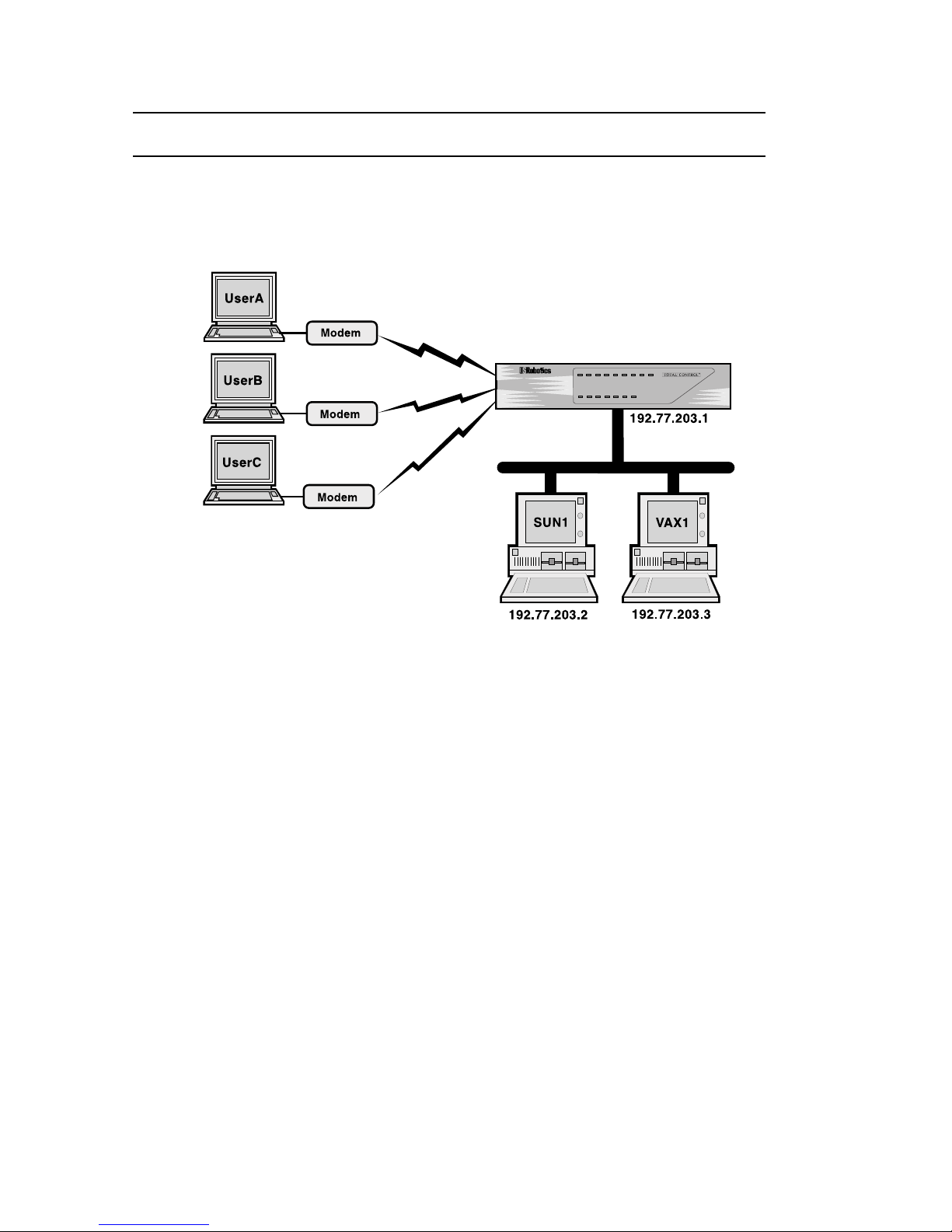
IP Terminal Server Case Studies
The following examples set up users to log into the two hosts in
the illustration below.
IP Terminal Server - Case Studies
Example 1
UserA, UserB, and UserC are all Login Users with entries in the
user table. An application on VAX1 is connected to a dial-up
information database that is open to the public (those not in the
user table).
Before you begin
Make sure the NETServer is properly configured.
• the NETServer must have an IP address assigned to it
• the NETServer’s netmask must match the one being used on
the local network.
See Minimum Configuration in Chapter 2 for instructions on how
to set these parameters.
4-12 IP Terminal Server Setup
Page 55

This example also assumes that Sun1 is the NETServer’s global
default host. The command to do this is:
set host 192.77.203.2
Por t Setup
The NETServer will use ports 6, 7, and 8 for this application.
set s6 login
set s7 login
set s8 login
Ports 6 and 7 will be used exclusively by users who already
have user accounts. We want the NETServer to perform its own
security checks and hang up on anybody not in the User Table
or in the RADIUS server’s database. Note that since we have
three user accounts but only two ports used for this purpose,
only two of the three users may be logged in at any one time.
set s6 security on
set s7 security on
Users connecting to these ports will be logging into Sun1 unless
their user table entries specify a different host. Sun1 also
happens to be the NETServer’s global default host.
set s6 host 192.77.203.2 (Sun1’s IP address)
set s7 host default
(Sun1 could also be specified this way)
By default, these users will be logging in with terminals emulating VT100s. Note that since security is on for this port, you
should not specify a port default login service. The NETServer
would never use such an entry.
set s6 termtype VT100
set s7 termtype VT100
Port 8 will be used as a public information line. We want
anybody to be able to dial into it.
set s8 security off
IP Terminal Server Setup 4-13
Page 56

Users connecting to the info line will be connected directly to a
database application running on VAX1 and will have no other
access to VAX1. Note that since netdata is talking directly to an
application, it will not relay terminal type information to the
host. Instead, it will relay exactly what the application outputs.
set s8 host 192.77.203.3 (VAX1’s IP address)
set s8 service_login netdata 6020
(Connect directly to application at TCP port# 6020)
User T able Setup
User A will be logging in to Sun1 with Rlogin. Since Sun1 is the
port default host, User A needs only a User name, a password,
and a login service in the User Table.
add user UserA password UserAPw
set user UserA service rlogin
User B can log into either SUN1 or VAX1. After he or she types
the correct user name and password, User B will be prompted
for a host name or IP address. User B will use the default login
service, Telnet.
add user UserB password UserBPw
set user UserB host prompt
UserC is a dialback user. When he or she enters the correct user
name and password, the NETServer will hang up and dial the
user back at 9, 555-1000. User C will use the port default host
(Sun 1) and Telnet. Note that the password does not have to be
defined on the same line as the user name.
add user UserC
set user UserC password callmeback
set user UserC dialback 9,555-1000
Save your work and reset all the ports
save all
reset all
4-14 IP Terminal Server Setup
Page 57

Example 2
Suppose you have a lot of potential users, but only a couple of
hosts, each of which has its own login security already set up for
each of its potential users. It may be easier to assign generic
user names for each host and let the hosts take care of user
authentication. In this example, SUN1 is a generic user name
for users of a Sun host. VAX1 is a generic user name for users of
a VAX host.
set s6 prompt Which Computer?
set s7 prompt Which Computer?
set s6 security on
set s7 security on
add user SUN1
set user SUN1 host 192.77.203.2
set user SUN1 service telnet
add user VAX1
set user VAX1 host 192.77.203.3
set user VAX1 service telnet
save all
reset all
When dialing into the NETServer, the user receives a “Which
Computer” prompt. If the user enters SUN1, a connection is
established with the Sun, which proceeds to authenticate the
user with its own security info. Since no terminal type has been
defined for the serial ports, all users will be defaulted to dumb
terminal emulation. The same would be true of the VAX.
IP Terminal Server Setup 4-15
Page 58

4-16 IP Terminal Server Setup
Page 59

Network Dial In Access
Network dial in users establish PPP or SLIP connections with
the NETServer and the local network. Unlike the “login users”
covered in the previous chapter, this kind of user is connecting
to the network as a virtual node rather than simply acting as an
input/output device (terminal) for an existing network node.
IPX dial-in users are all of this type.
Dial-in User Setup
The instructions below are required by all remote users dialing
in to the NETServer.
Chapter 5
1. The remote user’s computer must have communications
software that supports PPP or SLIP connections.
2. A PPP or SLIP protocol driver must be loaded on the remote
user’s computer for PPP or SLIP connections.
3. Set the modem to 8 data bits, No parity, and 1 stop bit.
Note: These are the default settings only. If you want to,
you can change what communications settings the
NETServer uses on each port. See Port Configuration, Serial
Communications Parameters in Chapter 10.
Network Dial In Access 5-1
Page 60

NETServer Setup for Network Dial-In (Over view)
This setup configures a NETServer for users to dial in to.
Note: This is a special case of LAN-to-LAN routing in which
the dial in network has only one node (an end user). For a more
complete understanding of how the NETServer handles these
functions, you may want to study Chapter 6 as well
Prework
Get the following information (Note that not all settings apply to
all applications):
IP Parameters
• The dial-in user’s IP address.
Note that if the dial-in user’s IP address is not important,
the NETServer may be told to simply assign the user an
address each time he or she dials in. The address can also be
negotiated by the NETServer and the user’s machine.
• The connection protocol (PPP or SLIP) that the user will
employ.
• The dial-in user’s subnet mask.
• The dial-in user’s Maximum Transmission Unit (MTU, the
largest packet size that the system will transmit) if applicable; both local and remote MTU’s must match.
• Whether or not the dial-in user is configured for Van
Jacobson compression.
IPX Parameters
IPX remote access sessions must use the PPP protocol and an
MTU of 1500. Note that when you assign an IPX Network
number to the user, the NETServer will automatically set these
things for you. Get the following information:
• A unique IPX Network Number that will represent the link
between the remote user and the local network for the
duration of the connection.
5-2 Network Dial In Access
Page 61

Configuration
A.
Configure at least one port for a network dial in connection.
See Configuring a Port, later in this chapter, for details.
B. Decide whether the dial in user is a normal user or a
dialback user. If the he or she is a dialback user, you must
create a Location Table entry for that user.
Note: Configuring the Location Table is not covered in this
chapter. For detailed information on the Location table see
Chapter 10. For a Location Table walkthrough, see Adding a
remote device to the Location Table in Chapter 6.
C. Create an entry in the User Table for each dial-in user. See
Adding a Remote User to the User Table, later in this chapter.
Network Dial In Access 5-3
Page 62

NETServer Dial-In (Detailed Setup)
To set up the NETServer software for this application:
• Configure at least one port
• Create a user table entry for each user
Configuring a Port
Ports used for this type of dial-in access should be configured as
Network ports that allow dial in.
Step 1 - Port Type
Set the port type. Usually, you would configure the port as a
network dialin port. If you will be configuring dialback users,
or will also be using the port for dial out routing, configure the
port as network twoway. Use the following command:
set s<port #> network <
dialin
|
twoway
|
hardwired
>
Hardwired: Setting a port to Hardwired tells the NETServer’s
operating software that you are establishing a synchronous
connection via a serial cable. Since s0 is the only serial port, this
is the only port for which the hardwired setting is valid.
If you configure s0 as Hardwired, set the following parameters
and go to Step 4. (For an explanation, see Ports Table, Hardwired
Port Parameters in Chapter 10).
• IP Address • Routing
• IPX Network Number • MTU
• Netmask • Compression
• Protocol
5-4 Network Dial In Access
Page 63

Step 2 - Optional friendly stuff
The following two parameters allow you to customize the port’s
printed response to dial in users. Note that Hardwired ports do
not use these settings.
Login Message
You can create a message (banner) that users will see prior to
login.
set s<port #> message <login message>
The login message can be up to 240 characters in length and
does not need to be surrounded by quotation marks (if you use
quotes, they will be included in the message). Use the carat ( ^ )
to designate the start of a new line. Example:
set s15 message U.S. Robotics^NETServer
Login Prompt
You can also customize the login prompt for each port. The
default prompt for network dial in ports is login:. Use the
following command:
set s<port #> prompt <login prompt>
If you use quotation marks, they will be included in the prompt.
Many automated login scripting systems expect a login prompt
to end in login:. Putting any character after the colon (including
quotation marks!) will cause some login scripts to crash.
Step 3 - Dialback Users on this Port?
If dialback users will be dialing into this port, it is a good idea
for the NETServer to be able to use the same port for dial out.
This makes sure that a dial out port will be available to dial the
user back. Part of this was done in Step 1, when you setup the
port as network twoway . The other thing that needs to be done
for a dial out port is assign the port to a dial group.
set s<port #> group <group # (0-99)>
Network Dial In Access 5-5
Page 64

Step 4 - Save your changes
Save the changes to flash memory:
save s<port #>
Reset the port so the changes take effect:
reset s<port #>
Adding a Remote User to the User Table
Note that user table entries do not need to be created for
Hardwired ports. Hardwired ports do not use this table.
5-6 Network Dial In Access
Page 65

Step 1 - Create a new user
Add the remote user to the User Table. Use the following
command:
add netuser <name> password <password>
Specifying a password is optional. In the example below, User1
will not be required to enter a password to get access to the
network.
add netuser User1
add netuser User2 password GumDrops
Step 2 - Normal or dialback user?
Normal users dial in and immediately initiate a session with the
network. When a dialback user dials in and types his or her
user name and password, the NETServer hangs up the line and
calls the user back. This can be useful if you want to reverse
charges on the phone bill.
If you are configuring a normal user, go to step three.
Dialback User Configuration
To configure a dialback user, type the following command:
set user <name> dialback <location>
<location> must be the name of a location table entry for the
dialback user. If you have not already done so, you must create
this location table entry. A list of location table commands can
be found in Chapter 10. A location table walkthrough can be
found in Chapter 6 under Adding the Remote Device to the Location
Table.
Since configuration for dial out connections is handled by the
location table, no further information needs to be added to a
dialback user table entry (you can skip to step 4).
Network Dial In Access 5-7
Page 66

Step 3 - Add configuration information for the user
You must set the following parameters. All other parameters are
optional.
IP Address
This is the dial in user’s IP address for the duration of the
connection. This address can be selected in three different ways.
Assigned The user is dynamically assigned an address from
a pre-defined pool of IP addresses. This requires
that an Assigned Address pool be defined (See
Global Configuration in Chapter 10).
Negotiated PPP connections only. The NETServer tries to
learn the remote computer’s IP address using
IPCP address negotiation.
IP address The user has a fixed IP address, which is specified
here.
Use the following command:
set user <name> destination <address>
The address can be assigned, negotiated or an actual IP address.
The last line in the example below is a specified address.
set user User1 destination assigned
set user User2 destination negotiated
set user User3 destination 192.77.24.127
IPX Network
If the dial in user wants to talk IPX, the connection between the
NETServer and the dialin user must have an IPX network
number assigned to it just like any cabled connection would.
Note that this number must be unique (not already used) on the
NETServer’s LAN and also must be unique to whatever network the dialin user may be connected to.
set user <name> ipxnet <IPX network #>
5-8 Network Dial In Access
Page 67

Protocol
Select the protocol to be used for the connection (PPP or SLIP).
Use the following command:
set user <name> protocol <
ppp
|
slip
>
IPX remote access sessions require the PPP protocol. If you have
specified an IPX Network Number, the NETServer will set this
to PPP automatically.
Netmask
This is the user’s IP subnet mask. Use the following command:
set user <name> netmask <netmask>
MTU
The Maximum Transmission Unit specifies the size of the largest
packet that may be sent to this user. IPX connections will
discard larger packets. IP connections will fragment larger
packets prior to transmission. Normally, this should be set to
the largest value that the user’s system can handle.
Valid PPP MTUs range from 100 to 1500 (default is 1500). Note
that PPP allows a remote system to negotiate a smaller MTU if
needed. Valid SLIP MTUs range from 100 to 1006 (default is
1006).
set user <name> mtu <value>
IPX connections require an MTU of 1500. When you assign an
IPX Network Number, the NETServer will set this to 1500
automatically.
Network Dial In Access 5-9
Page 68

Routing
Set the level of RIP messaging that the two devices will exchange during the connection. Use the following command:
set user <name> routing <option>
<option> can be any one of the following:
broadcast Send dynamic routing information to the dial in user
(but do not listen)
listen Listen for dynamic routes received from the dial in
user (but do not broadcast)
on Do both of the above
off Do not send dynamic routing information. Ignore
dynamic routes received
Compression
If using SLIP, enable Van Jacobson IP header compression only if
both networks use CSLIP (compressed SLIP).
If compression is enabled for a PPP connection, the NETServer
will attempt to negotiate for compression, but will not use it if
the remote site does not support compression.
set user <name> compression <on |
off
>
Step 4 - Save your changes
Use the following command:
save user
5-10 Network Dial In Access
Page 69
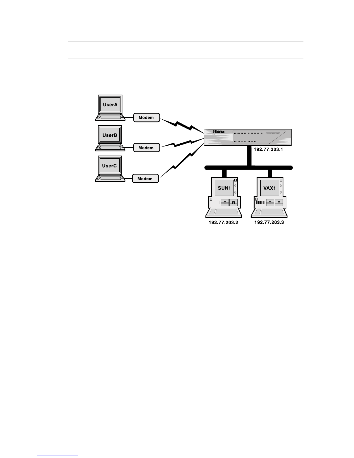
IP Remote Access Case Study
UserA, UserB and UserC will be dialing to connect with the
local network. UserC will be a dialback user.
IP Remote Access Case Study
This case study assumes the following:
• The configuration will take place from the Command Line
• The NETServer has the correct IP address and netmask
• All other settings remain at factory defaults
Configure the ports
This example will use ports 3 and 4 to answer calls from dial in
user. In order to accommodate the dialback user, port 4 will also
be configured for dial out.
set s3 network dialin
set s4 network twoway
When users connect to the port, the NETServer will greet them.
Although the greeting says the same thing. Port 3 will write it
all on one line, while port 4 will split it up over three lines.
set s3 message Welcome to the Computer Center
set s4 message Welcome^to the^Computer Center
Network Dial In Access 5-11
Page 70

Create user table entries for the dial in users
Use the following commands to create User A:
add netuser userA password userApw
set user userA address 192.77.203.100
set user userA netmask 255.255.255.0
set user userA protocol ppp
set user userA mtu 1500
set user userA routing on
User B will be configured to use CSLIP (Compressed SLIP)
add netuser userB password userBpw
set user userB address 192.77.203.101
set user userB netmask 255.255.255.0
set user userB protocol slip
set user userB compression on
set user userB mtu 1006
set user userB routing on
Create a user table entry for the dialback user
Only two lines are requir ed for the dialback user table entry.
The user table configures dial in connections. The NETServer
dials OUT to a dialback user. The first line looks like this:
add netuser userC password callmeback
Dial out connections are configured with the location table. The
second line of the user table entry specifies the location to use.
Before we can this line to the user table, we must create the
location to be used. Note that the location type is manual, since
we want the NETServer to dial the user only when it is specifically asked to do so.
add location sales_1
set location sales_1 manual
set location sales_1 destination 192.77.203.102
set location sales_1 netmask 255.255.255.0
set location sales_1 protocol ppp
set location sales_1 mtu 1500
set location sales_1 routing on
set location sales_1 script 1 “atdt5551000\r” ”CONNECT”
(To contact UserC, dial 555-1000 and wait for “CONNECT”)
5-12 Network Dial In Access
Page 71

A modem group must be defined to tell the NETServer which
modems it can use to dial out to the location. Note that since
only serial port 4 was configured for dial out use, the group we
create will contain only port 14.
set s4 group 1
set location sales_1 group 1
Maxports (the maximum number of ports that can be used to
dial out to a location) must be set to something other than its
default (0).
set location sales_1 maxports 1
For a more in-depth discussion of location table entries, please
see Adding a remote device to the Location Table in Chapter 6.
Finishing the user table entry
Now that we have created the location, we can add the second
line of the user table entry. It looks like this:
set user userC dialback sales_1
Save your work and reset the ports
Use the following commands:
save all
reset s3
reset s4
Network Dial In Access 5-13
Page 72

Connecting to the NETServer
The users are now ready to connect to the local network. When
they dial into the NETServer from a communications software
package, they will see a login message (banner) and prompt.
If UserA and UserB respond to the User Name and Password
prompts correctly, the NETServer connects them to the network.
If userC types in its user name and password at the login
prompt, the NETServer sends the message ”Dialback Accepted .
. .” and disconnects. UserC must set his modem to Auto Answer
(usually with ATS0=1). The NETServer dials the user back,
using the number entered as part of the location dial script.
Once connected to the network, users can run TCP/IP software
such as Novell’s LAN workplace to telnet, ftp, and so on to
other hosts on the network.
Note: Users with software supporting automated dialing, such
as Chameleon, may not see the login banner or prompt.
5-14 Network Dial In Access
Page 73
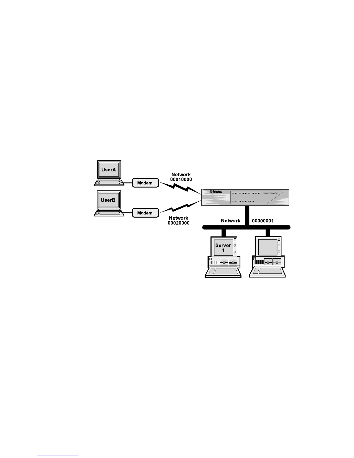
IPX Remote Access
This case study assumes the following:
• The configuration will take place from the Command Line
software.
• The NETServer is configured with the correct IPX network
number, IPX Frame Type, and Sysname.
• The NETServer is set to the factory defaults on all other
settings.
• Two users want access to a Novell server on the
NETServer’s network (userA and userB).
Configure the ports
Ports 3 and 4 will be used for this application. Set them both to
network dialin.
After connecting to either port, the user will receive a welcome
message. Use the following command:
IPX Remote Access Case Study
set s3 network dialin
set s4 network dialin
set s3 message Welcome to the Computer Center
set s4 message Welcome to the Computer Center
Network Dial In Access 5-15
Page 74

Create User Table entries for the dial in users
Use the following commands to create an IPX user account for
UserA:
add netuser userA password userApw
set user userA ipxnet 00010000
set user userA protocol ppp
set user userA mtu 1500
set user userA routing on
UserB also has both the IP and the IPX protocol stacks loaded on
his machine. So, we’ll tell the NETServer what his IP address is
just in case he ever wants to talk IP across the link.
add netuser userB password userBpw
set userB address 192.77.203.5
set userB netmask 255.255.255.0
set user userB ipxnet 00020000
set user userB protocol ppp
set user userB mtu 1500
set user userB routing on
Save your work and reset the ports
Use the following commands:
save all
reset s3
reset s4
5-16 Network Dial In Access
Page 75

Chapter 6
LAN-to-LAN Routing
The NETServer can perform IP or IPX LAN-to-LAN routing
with a remote NETServer or third party router. This chapter
assumes that the basic installation of all involved routing
devices has already been performed.
Setup for NETServer Routing (Overview)
Before you begin, obtain the following information. These items
are required for routing connections:
TCP/IP routing
• An IP address to connect to. If the remote device is another
NETServer, you may use its Net0 IP address (the address
you assigned during the startup procedure).
Some routing devices have an IP address assigned to each
port rather than just one IP address for the whole box. If
this is the case with the remote device, use the address of the
port you want to connect to.
• The connection protocol (PPP or SLIP) the NETServer will
use. If routing IPX, the NETServer will set this for you (as
PPP).
• The remote system’s netmask
• The Maximum Transmission Unit (MTU, the largest packet
that the NETServer will send to the remote device); both
local and remote MTUs must match.
• Whether or not the remote device is configured for Van
Jacobson compression.
LAN-to-LAN Routing 6-1
Page 76

IPX routing
• An IPX network number that will represent the connection
between the two devices. This number must not already
exist on either network.
• IPX connections must use the PPP protocol and an MTU of
1500. When you assign an IPX network number to the
connection, the NETServer will set these values automatically.
Configuration
Configure at least one NETServer port for a connection with
A.
the remote device. See Configuring a Port, later this chapter.
B. If you want to use dynamic routing during the connection,
set the Routing (RIP messaging) for the port you intend to
use to Broadcast & Listen (On).
If you do not want to use dynamic routing, shut RIP
messaging off. It only clutters the interface, slowing traffic.
C. If the remote device will be dialing in to this NETServer, you
must create a User Table entry (Network User) for it. See
Adding a Remote Device to the User Table, later in this chapter.
D. If this NETServer will be dialing out to the location, you
must create a Location Table entry for the remote device.
See Adding a Remote Device to the Location Table, later in this
chapter.
E. If you are using PPP, you can also use CHAP authentication.
This requires some special configuration:
• Regardless of whether the NETServer is dialing out to a
remote device or authenticating a dial in device, it must
have a (network user) user table entry for the User ID
that the remote device will send. (If the remote device is
another NETServer, it will send its Sysname).
• The Password in this user table entry must be the CHAP
shared secret.
• The remote device must be configured to look up this
same password when it receives the User ID (Sysname)
that the NETServer will send.
See PAP and CHAP authentication, later in this chapter for
more information.
6-2 LAN-to-LAN Routing
Page 77

F. Test the connection from both sites. See Testing the Connec-
tion, later in this chapter for details.
LAN-to-LAN Routing 6-3
Page 78

An Introduction to NETServer Routing
Some network devices, such as Router 1 and Router 2 in the
drawing below, have more than one network interface, allowing
them to be attached to multiple network segments. Such
devices allow data from one end of a large network to be
forwarded to the other end. This process is called routing. If a
packet of data must pass through more than one routing device
to reach its destination, all the routing devices involved must
know how to pass a packet onto the next router (also called next
hop” or “gateway”) on the way to the destination.
A
Router 1
B
Notice that Router 1 can’t forward the packet to segment C
directly because it isn’t directly connected to segment C. All
Router 1 needs to know is that it should send packets destined
for segment C to Router 2. Router 2 takes care of the rest.
Similarly, if there was a segment D on the other end of segment
C, Router 1 would still only need to know that the “next hop”
toward that destination was Router 2.
NETServer Routing
When the NETServer receives a packet that is addressed to
another device, it routes that packet toward its destination. To
make routing decisions, the NETServer looks up the packet’s
destination address in its Routes Table, which contains the
Router 2
C
6-4 LAN-to-LAN Routing
Page 79

addresses of “Gateways” (next hops) through which packets
should be forwarded when they are headed for given destination addresses. A gateway can be a host, a server or any other
device that performs routing functions
In the drawing below, the NETServer would require an entry for
segment C in its routes table in order to forward packets going
from network segment A to C. The entry would contain C as a
destination address and the address (on segment B) of the
gateway (next hop) needed to get there.
Note that even though network segment B uses two modems to
transfer data rather than a physical cable, it looks like a cabling
segment to Network A and Network C.
With such an entry in place, the NETServer can pick up packets
on A that are bound for C and sends them to the gateway. The
gateway handles the rest.
LAN-to-LAN Routing 6-5
Page 80

Static vs. Dynamic Routes
Static routes are user-defined. By adding entries to the Routes
Table, you tell the NETServer how to forward packets bound for
specific networks.
RIP
Fortunately, most networks don’t require you to build routing
tables by hand. All IPX and most IP networks use a protocol
that builds routing tables dynamically to reflect changing
network conditions. IPX servers and routers use Novell’s
Routing Information Protocol (RIP) to communicate what
network segments they have access to. Many IP machines also
use a protocol called RIP. These are completely different protocols, but they accomplish the same thing in roughly the same
manner. The NETServer handles both protocols identically.
When you execute a command that affects RIP messaging, both
versions of the protocol are affected.
How RIP Dynamically Builds the Routing Table
Network devices running RIP (either version) broadcast the
addresses of the network segments which they know how to get
to. Routing tables are built by listening to the broadcasts of
other machines.
In the example above, the NETServer would learn about
network segment C through a broadcast from the routing device
joining B and C. This device would then be added to the routing
table as a gateway leading to C. The NETServer might also hear
the same routing device advertising a route to network segment
B. But, since the NETServer already has a better route to
segment B (a direct one), the broadcast would be ignored.
If the NETServer does not periodically hear a broadcast for a
given (dynamic) route, the route will be assumed unavailable
and deleted from the table. Static routes remain in the table
until removed by the administrator.
If you have defined a static route to a given location, the
NETServer assumes you want that route used and ignores
dynamic routing broadcasts pointing to the same location.
6-6 LAN-to-LAN Routing
Page 81

How Packets are Routed
When the NETServer receives a packet, it looks up the packet’s
destination in its routing table. If a static route is found, the
packet is sent to the gateway listed. If a static route is not found,
the NETServer will use a dynamic route. If the routing table
contains no routes to the destination, it will send the packet to
the Default Gateway. If no such gateway has been defined, the
packet is discarded.
Establishing Connections to Remote Gateways
The NETServer can easily forward a packet to a gateway for
which there is an established connection, such as a gateway on
the same segment of the local LAN or at the other end of an
active dial-up connection. All the NETServer has to do in these
situations is send the packet out the right port.
However, when there is no existing connection, the NETServer
has to do a bit more work. The Location table contains a list of
remote gateways that the NETServer can dial into. When the
NETServer does not have a connection to a packet’s next hop, it
looks up the address of the gateway in the Location table. The
Location Table should contain a “dial script” which tells the
NETServer how to contact the remote location.
Dial Scripts are most useful for on-demand routing sessions. In
these situations, the NETServer connects to a remote gateway
only when it has packets queued for that location.
LAN-to-LAN Routing 6-7
Page 82
Incoming
Packet
Routing Procedure
Static
(user defined)
next hop in Routes
Table?
Yes
Connection to
"Next Hop"
Established?
Yes
Forward
Packet to
Next Hop
No
No
Yes
route to destination
listed in Location
Listening for
RIP Messages?
Yes
Dynamic
in Routes
Table?
Next hop
Table?
Yes
Establish
connection to
next hop
No
No
No
No
Default Gateway
(Next Hop)
Defined?
Yes
No
Trash
Packet
Destination X
6-8 LAN-to-LAN Routing
TM
NETServer/16
Page 83

PAP/CHAP Authentication
The NETServer supports auto-detecting the PAP and CHAP
methods of login authentication on PPP connections. If a user
dials in and starts sending PPP packets, the NETServer asks that
the user log in with PAP (enter a user name and password). If
the user refuses PAP authentication, the NETServer demands
CHAP authentication. If this is also refused, the NETServer
hangs up.
Security Note: PAP is a less secure authentication method than
CHAP since user names and passwords are passed over the link
in “clear text” (in other words, they are not encrypted). For this
reason, it is possible to force CHAP authentication by disabling
PAP support. The command to do this is:
set pap off
PAP (Password Authentication Protocol)
PAP is simply a fancy way of saying that the dialing user or
system will respond to the User Name and Password prompts
given by the authenticating system. Although the NETServer
will not initiate dial out PAP authentication, you can accomplish
the same effect by creating a dial script containing the expected
prompts and the r equired responses.
However, the NETServer will respond to a dial-in PAP authentication request. All that is needed is a User Table entry for the
remote device.
CHAP (Challenge Handshake Authentication Protocol)
Instead of actually sending a password over the link, CHAP
relies on a “shared secr et”, a password that both sides of the
connection know, but never send. When a remote system
requests CHAP authentication, the authenticating host r eplies
with a challenge packet. The challenge packet contains (among
other things):
• A user name for the host. The challenged system needs this
to look up the correct “shared secret” password.
LAN-to-LAN Routing 6-9
Page 84

• A “challenge value” (a randomly generated string of
characters)
The challenged system then concatenates the challenge value
with the shared secret and passes the new string through a
hashing algorithm. When the hashing algorithm has formed a
response based on this string, the challenged system replies with
a packet containing both the response value and a user name.
The authenticating host looks up the correct password for the
user name received and then performs the same calculations the
client performed, comparing the result to the response value
received. If the results match, the challenged system is allowed
to pass through. However, the authenticating host can issue
additional CHAP challenges at any time during the connection.
Note: both ends of the connection must be using the same
hashing algorithm for the connection to succeed. The
NETServer uses an algorithm called MD5.
CHAP Setup for the NETServer
Because both sides of a CHAP connection need to look up a
password, each side requires a user table entry for the other
system. Note that each of these user table entries must have a
password and the passwords must be identical.
• Whether dialing in or authenticating, the NETServer puts its
Sysname in the user name field. This means that the remote
system must have a user table entry with this user name.
• The NETServer must have a (network user) user table entry
for the user name the remote system sends. Note that if the
remote device is another NETServer, it will be sending its
Sysname.
• These user table entries must not be configured as dialback
users.
6-10 LAN-to-LAN Routing
Page 85

A CHAP Challenge Example
At the Corporate site is a NETServer with the Sysname of
NETSERVE. A typical authentication might resemble the
following:
1. A remote NETServer establishes a connection and negoti-
ates for an authentication procedure.
2. NETSER VE becomes responsible for issuing a CHAP
challenge. Inside that challenge is a User Name string
containing the name NETSERVE and the random challenge
string LASDFH;LASD.
3. When the remote NETServer receives the challenge, it
checks its local User Table for the entry NETSERVE.
4. Finding the entry, the remote NETServer learns the shared
secret password CHAP_PW and passes the string
CHAP_PWLASDFH;LASD through MD5.
5. MD5 forms a response which the remote NETServer sends
back to NETSERVE. Contained within the response is a
User Name containing the Sysname of the remote
NETServer.
6. NETSERVE then looks in the User Table for the name of the
remote NETServer, and uses the password and the challenge
string to validate the CHAP response received from the
remote NETServer.
7. If the password comparison is successful, NETSERVE will
then send a CHAP successful message back to the remote
NETServer and the connection is complete. If the MD5
comparison fails, a CHAP failure message is sent to the
remote NETServer and the process r epeats.
LAN-to-LAN Routing 6-11
Page 86

LAN-to-LAN Routing (Detailed Setup)
The following section gives details on configuring routing from
the command line. To attach to the command line software, see
Connecting to the Command Line in Chapter 2.
Configuring the Port
Ports used for LAN-to-LAN routing need to be configured as
Network ports.
Step 1 - Port Type
The port must be configured as a network port with one of the
following options. Dial In, Dial Out, Dial In & Dial Out
(twoway), or Hardwired. Use the following command:
set s<port #> network <
dialin
|
dialout
|
twoway
|
hardwired
>
Hardwired: Setting a port to Hardwired tells the NETServer’s
operating software that you are establishing a synchronous
connection via a serial cable. Since s0 is the only serial port, this
is the only port for which the hardwired setting is valid.
If you configure s0 as Hardwired, set the following parameters
and go to Step 3. (For an explanation, see Ports Table, Hardwired
Port Parameters in Chapter 10).
• IP Address • Routing
• IPX Network Number • MTU
• Netmask • Compression
• Protocol
6-12 LAN-to-LAN Routing
Page 87

Step 2 - Creating a Dial-Out Group
Dialout and Twoway ports only. If the NETServer will dial out
to a remote location, you must create a group of modems that
can be used to dial out to the location. Note that you must do
this even if only one modem will be used for that particular
location. The following command creates such a group:
set s<port #> group <group #>
<group #> is any number from 0 to 99. The example below
creates group #2, which consists of ports 5 and 6:
set s5 group 2
set s6 group 2
Step 3 - Save your work
Save the changes to flash memory. Use the following command:
save s<port #>
Reset the port so the changes take effect by using the following
command:
reset s<port #>
LAN-to-LAN Routing 6-13
Page 88

Adding a Remote Device to the Location Table
This is required only if the NETServer will dial out to the remote
location. If the NETServer will not be initiating connections to
the remote location (the remote device will always do the
dialing), you may skip to the section titled Adding a Remote
Device to the User Table.
Step 1 - Create a new location table entry.
Use the following command:
add location <location name>
The Location Name can be up to 15 characters long.
Step 2 - Set Required Location Parameters.
The parameters listed below must be set:
Type
The following command determines when the NETServer will
dial out to the remote location:
set location <location> <
on_demand
|
manual
|
continuous
>
On Demand The NETServer dials out to the remote device
when it has packets queued for that location. It
then maintains the connection only as long as
there is traffic on the line. Note that dynamic
routing information is updated while there is a
connection between the two devices, but not
before the NETServer dials or after it hangs up.
When an on-demand connection is terminated,
the NETServer retains current RIP and SAP
information in memory (stops aging it). It then
uses these last known values to “spoof” (fake) RIP
and SAP broadcasts to active LAN and WAN
connections. When an on-demand connection is
first created, the NETServer will immediately
attempt to dial the remote location to obtain some
initial RIP and SAP values.
6-14 LAN-to-LAN Routing
Page 89

Manual (Used for debugging) The NETServer dials out
only when it receives a dial command fr om the
command line.
Continuous The NETServer will attempt to maintain the
connection at all times. If the connection is
broken it will dial again.
Example:
set location Atlanta on_demand
Protocol
Select the protocol to be used for the connection (PPP or SLIP).
Use the following command:
set location <location name> protocol <
ppp
|
slip
>
IPX LAN-to-LAN routing requires the PPP protocol. If you have
assigned an IPX Network Number, the NETServer will select
PPP automatically.
IP Address
This is the remote device’s IP address.
set location <location name> destination <IP address>
If the connection will use PPP and the location has been configured as Manual or Continuous, the IP address can be set to
255.255.255.255, which tells the NETServer to learn the IP
address of the remote system using IPCP address negotiation.
IPX Network
This is the unique IPX network number that the NETServer and
the remote device will share for the duration of the connection.
It does not designate a physical network cable. This network
number refers to the dial up connection itself. Use the following
command:
set location <location name> ipxnet <IPX network #>
LAN-to-LAN Routing 6-15
Page 90

Netmask
This is the remote network’s IP subnet mask. Use the following
command:
set location <location name> netmask <netmask>
MTU
The Maximum Transmission Unit specifies the size of the largest
packet that may be sent to this location. IPX connections will
discard larger packets. IP connections will fragment larger
packets prior to transmission. Normally, this should be set to
the largest value that the remote network can handle. However,
an IP connection using multi-line load balancing may benefit
from a smaller MTU (see Step 3, below).
Valid PPP MTUs range from 100 to 1500 (default is 1500). Note
that PPP allows a remote system to negotiate a smaller MTU if
needed. Valid SLIP MTUs range from 100 to 1006 (default is
1006). Use the following command:
set location <location name> mtu <value>
IPX LAN-to-LAN routing requires an MTU of 1500. If you have
assigned an IPX Network Number, the NETServer will set this
to 1500 automatically.
Routing
Set the level of RIP messaging that the two devices will exchange during the connection. Use the following command:
set location <location name> routing <
broadcast
|
listen
| on |
off
broadcast Send dynamic routing information to the remote
device. (but do not listen)
listen Listen for dynamic routes received from the remote
device. (but do not broadcast)
on Do both of the above.
off Do not send dynamic routing information. Ignore
dynamic routes received.
>
6-16 LAN-to-LAN Routing
Page 91

Compression
If using SLIP, enable Van Jacobson IP header compression only if
both networks use CSLIP (compressed SLIP).
If compression is enabled for a PPP connection, the NETServer
will attempt to negotiate for compression, but will not use it if
the remote site does not support compression. Use the following command:
set location <location name> compression <on |
Dial Group Number
off
>
Specifies which pool of modems will dial out to the remote
location. Range is 0 to 99. The NETServer will only use ports
that belong to this group to dial out to the remote location. The
default is 0. Use the following command:
set location <location name> group <group #>
Idle Time-out
Applies to Manual and On Demand locations only. This field
specifies how many minutes a dial out connection to this
location can remain idle (no packets being sent or received)
before the NETServer disconnects. The idle timer ignores RIP,
SAP and keepalive packets, allowing ports to time-out even
though these protocols are running. The default is 0 (disable
idle time-out). Use the following command:
You must set the Idle T ime-out field to something other than its
default (no time-out) for on-demand locations. If you don’t do
this, the initial connection will stay up permanently.
set location <location name> idletime <2 to 240 minutes>
LAN-to-LAN Routing 6-17
Page 92

Step 3 - Multiple lines for a single connection
When talking to other NETServers, the NETServer can spread a
single TCP/IP connection over multiple lines (increasing
throughput). Individual IPX clients/socket connections will
show little (if any) benefit from this technique. However,
because load balancing is employed, this technique may allow
you to pipe more IPX clients/socket connections through the
same bandwidth. There are two parameters used to set this up:
High Water Mark and Maximum Ports. Furthermore, there is
some additional setup needed to allow the dialing NETServer to
dial multiple numbers from a single location table entry.
High Water Mark
Determines when the NETServer should open an additional
connection to a remote NETServer. The NETServer will open
another port if all of the following are true:
• The number of bytes queued for the remote location exceeds
the High Water Mark
• There is an available port in the location’s dial group
• The number of ports currently being used for the connection
is less than the Max Ports setting.
Default is 0 (immediately open Max Ports lines every time).
If you configure a small high water mark, the NETServer will
use an additional line whenever one is available. A larger high
water mark will cause the NETServer to use additional lines
only when they are really needed, leaving them free for other
uses. Keep in mind the kind of traffic you expect across the link.
Light traffic, such as a user Telnet session, will usually only
queue a few hundred bytes. File transfers, on the other hand,
can easily queue several thousand. Use the following command:
set location <location> high_water <bytes>
6-18 LAN-to-LAN Routing
Page 93

Maximum Ports
Sets the maximum number of ports the NETServer can use for a
single connection to the remote location. Use the following
command:
set location <location name> maxports <0 .. 16>
0 (default) disable dialout to the location.
1 Use only one port for a connection. This setting must be
used if the remote device is not another NETServer.
2+ When the number of bytes queued for the remote location
exceeds the High Water Mark, another line will be added to
the connection if it is available.
Additional setup for multiple line connections
A NETServer on the answering end of a connection must receive
each incoming call on a different line even though the other
NETServer is dialing the same number every time (there is only
one dial script per location). There are two ways to accomplish
this:
The first is to have a single phone number on the receiving end
of the connection set up on a hunt group. A hunt gr oup routes
calls through a single phone number out to the first available
line.
LAN-to-LAN Routing 6-19
Page 94

The second method is to configure each modem to dial a different stored number. This is done using the modem’s A T&Z
command. You can send this command to the modem from the
NETServer’s command line by typing the following:
set s<port #> at “AT &Z<slot #>=<phone number>\r”
<slot#> is the position (0-9) in the modem’s non volatile memory
(each modem stores up to ten numbers).
Repeat for each modem in the dial group. Note that a different
phone number must be stored for each modem, but <slot#>
must be the same for all modems.
Step 4 - Create a Dial Script
Dial scripts tell the NETServer how to dial and, if necessary, log
into a remote location. Each line of a dial script contains a send
string and a reply string. The NETServer issues the send string
to the port making the connection and then waits until it receives the reply string.
The send strings should end with a \r (carriage return) character.
reply strings ar e case-sensitive. Also, the send and reply options
must be enclosed in quotes (“ ”).
set location <location> script <line #> “<send>\r” “<reply> ”
To dial 555-1000 and wait for a CONNECT message from the
modem:
set location Chicago script 1 “atdt5551000\r” “CONNECT”
Note: Waiting for a CONNECT message from the internal
modem requires that the modem be configured to respond with
verbal result codes (add the AT commands Q0V1 to the init
string of each modem). If the modem is not configured to send
verbal result codes, the NETServer will wait indefinitely for a
message that does not arrive.
Alternatively, try putting the remote systems “login:” prompt in
the expect string instead of the connect message.
6-20 LAN-to-LAN Routing
Page 95

If you had configured this location to use multiple lines without
a hunt group (see Step 3), you would configure the NETServer
to use whichever number the modem has stored, rather than
giving it the number explicitly. Since each modem has a different number stored, each will dial a different number. Example:
set location Chicago script 1 “atds<slot#>\r” “CONNECT”
For detailed information on dial scripts, see Dial Scripts in
Chapter 10. Consult your modem reference guide for information on AT commands supported.
Step 5 - Save your changes
Use the following command:
save location
LAN-to-LAN Routing 6-21
Page 96

Adding the Remote Device to the User Table
Adding a user table entry is required if the remote device will be
dialing into the NETServer.
It is only required for dial out connections if you want to use
CHAP authentication on a PPP connection.
Step 1 - Create a User Table Entry
Type in a user name and password:
add netuser <user name> password <password>
Note: If you plan to use CHAP authentication, the password
defined here is the CHAP shared secret. The shared secret must
be the same on both devices. The User Name you enter here
must be the system ID that the remote device will send during a
CHAP challenge (Another NETServer will send its Sysname).
Step 2 - Tell the NETServer about the Remote Device
You must set the following parameters.
IP Address
This is the IP address that the remote device uses for the duration of the connection. Use the following command:
set user <user name> address <IP address>
IPX Network
Use the following command to assign an IPX network number
to the connection between the NETServer and the remote
device:
set user <user name> ipxnet <IPX network #>
Note that this number cannot already be used on any network
attached to the NETServer or any network attached to the
remote device.
6-22 LAN-to-LAN Routing
Page 97

Protocol
Select the protocol to be used for the connection (PPP or SLIP).
Use the following command:
set user <user name> protocol <
ppp
|
slip
>
IPX LAN-to-LAN routing requires the PPP protocol. If you have
assigned an IPX Network Number, the NETServer will set this
to PPP automatically.
Netmask
Use the following command to tell the NETServer the remote
network’s IP subnet mask:
set user <user name> netmask <netmask>
MTU
The Maximum Transmission Unit specifies the size of the largest
packet that may be received from the remote location. IPX
connections will discard larger packets. IP connections will
fragment larger packets. Normally, this should be set to the
largest value possible. However, an IP connection using multiline load balancing may benefit from a smaller MTU (see Step 3
of Location setup, earlier in this chapter).
Valid PPP MTUs range from 100 to 1500 (default is 1500). Note
that PPP allows remote systems to negotiate a smaller MTU if
needed. Valid SLIP MTUs range from 100 to 1006 (default is
1006).
set user <user name> mtu <value>
IPX LAN-to-LAN routing requires an MTU of 1500 If you have
assigned an IPX Network Number, the NETServer will set this
to 1500 automatically.
LAN-to-LAN Routing 6-23
Page 98

Routing
Set the level of RIP messaging that the two devices will exchange during the connection. Use the following command:
set user <user name> routing <
broadcast
|
listen
| on |
off
>
broadcast Send dynamic routing information to the remote
device. (but do not listen)
listen Listen for dynamic routes received from the remote
device. (but do not broadcast)
on Do both of the above.
off Do not send dynamic routing information. Ignore
dynamic routes received.
Compression
Van Jacobson TCP/IP header compression should be enabled for
a SLIP connection only if both the local NETServer and the
remote device are configured to use compressed SLIP (CSLIP).
Both sides must agree on whether to use compression or the
connection will fail.
Enabling compression on a PPP connection will cause the
NETServer to negotiate for compression. Compression will be
used only if the remote device supports it. Use the following
command:
set netuser <user name> compression <on |
Step 3 - Save your changes
Use the following command:
save user <user name>
6-24 LAN-to-LAN Routing
off
>
Page 99
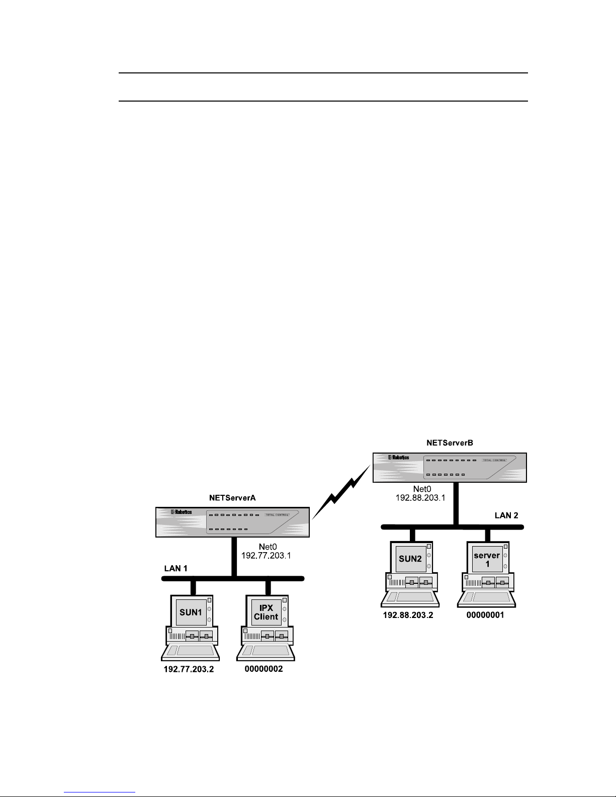
LAN-to-LAN Routing Case Study
The following example shows routing between two NETServers
in order to demonstrate how each end of the connection would
be configured.
This case study assumes the following:
• both NETServers (NETServerA and NETServerB) are
configured with the correct IPX network number, IPX Frame
Type, IP address and Netmask.
• NETServerA’s Sysname is NSA. NETServerB’s Sysname is
NSB.
• both NETServers are set to the factory defaults on all other
settings
• NETServer A is on LAN1, the main data center of a com-
pany, and NETServer B is on LAN2, a branch office.
• if traffic on the connection becomes too great, NETServerB
will open a second line
• if there is no traffic on the connection for 30 minutes,
NETServer B disconnects
Case Study - LAN to LAN Routing Between Two NETServers
LAN-to-LAN Routing 6-25
Page 100

This example will set up two NETServers for LAN-to-LAN
routing. NETServer B will be configured to dial NETServer A
on demand. In other words, when packets are waiting to be
transferred, NETServer B will form a virtual connection to
NETServer B. When the connection is no longer needed, it is
terminated.
Setting Up NETServer A
NETServer A will use ports 7 and 8 to handle incoming routing
from NETServer B. (Technically, these lines are unnecessary on
a new NETServer since the factory default, login network dialin,
will work just as well).
set s7 network dialin
set s8 network dialin
Since NETServer B will be dialing in to form a network connection, NETServer B is a network user. It will need an entry in
NETServer A’s user table.
add netuser nsb password xyzabc
(For CHAP, “nsb” is NETServer B’s Sysname)
set user nsb address 192.88.203.1
set user nsb netmask 255.255.255.0
set user nsb ipxnet 2
The NETServers will exchange dynamic routing information
(RIP packets) with each other.
set user nsb routing on
Save your work and reset the ports.
save all
reset all
6-26 LAN-to-LAN Routing
 Loading...