

Us robotics 3453 Quick Installation Guide for Windows 95, 98, NT, 2000, Me, XP Operating Systems
Page 1

CourierTM 56K Corporate Modem
Quick Installation Guide for
Windows 95, 98, NT, 2000, Me, XP Operating
Systems
Model 3453
Part Number R24.0331.00
Page 2

Page 3

U.S. Robotics Corporation
935 National Parkway
Schaumburg, Illinois
60173-5157
USA
No part of this documentation may be reproduced in any form or by any means or used to make any
derivative work (such as a translation, transformation, or adaptation) without written permission from
U.S. Robotics Corporation. U.S. Robotics Corporation reserves the right to revise this documentation
and to make changes in the products and/or content of this document from time to time without obli-
gation to provide notification of such revision or change. U.S. Robotics Corporation provides this docu-
mentation without warranty of any kind, either implied or expressed, including, but not limited to,
implied warranties of merchantability and fitness for a particular purpose. If there is any software on
removable media described in this documentation, it is furnished under a license agreement included
with the product as a separate document, in the hard copy documentation, or on the removable media
in a directory file named LICENSE.TXT or !LICENSE.TXT. If you are unable to locate a copy, please con-
tact U.S. Robotics and a copy will be provided to you.
UNITED STATES GOVERNMENT LEGEND If you are a United States government agency, then this docu-
mentation and the software described herein are provided to you subject to the following:
All technical data and computer software are commercial in nature and developed solely at private
expense. Software is delivered as “Commercial Computer Software” as defined in DFARS 252.227-
7014 (June 1995) or as a “commercial item” as defined in FAR 2.101(a) and as such is provided with
only such rights as are provided in U.S. Robotics standard commercial license for the Software. Techni-
cal data is provided with limited rights only as provided in DFAR 252.227-7015 (Nov 1995) or FAR
52.227-14 (June 1987) whichever is applicable. You agree not to remove or deface any portion of any
legend provided on any licensed program or documentation contained in, or delivered to you in con-
junction with, this Quick Installation Guide.
Copyright © 2002 U.S. Robotics Corporation. All rights reserved. U.S. Robotics and the U.S. Robotics
logo are registered trademarks of U.S. Robotics Corporation. Other product names are for identifica-
tion purposes only and may be trademarks of their respective companies. Product specifications sub-
ject to change without notice.
English
Page 4

Page 5

Related Documentation
You will find more detailed technical information on the Installation CD-ROM that
came with your modem.
Product Features
V. Everything Technology
The modem supports all key ITU analog communications protocols and many
proprietary ones to provide you with ultimate compatibility. The modem also
supports V.25bis synchronous mode using bisync and HDLC protocols and 2wire leased line operations for compatibility with many legacy systems.
V. Ever ywhe re Tec hno l ogy
The V.Everywhere technology in this modem allows this modem hardware and
firmware to be used anywhere in the world. A simple setup to configure the
modem for the country of operation is all that is required.
Remote Flash
You can easily upgrade your modems in the field from the convenience of your
local office by enabling the remote “flash” capability of the modem. See the
“Upgrading” chapter of the Command Reference included on the Installation CDROM.
Dial and Dialback Security
The modem provides you with a robust mechanism for providing dial and
dialback security for your network. See the “Dial Security” chapter of the
Command Reference included in the Installation CD-ROM.
Remote Manageability
The modem can be remotely configured and monitored for the convenience of
your local office. See the Accessing and Configuring Remotely chapter of the
Command Reference included in the Installation CD-ROM.
Additional Features
For additional features supported by this modem, refer to the Command
Reference included in the Installation CD-ROM.
Before You Begin: Prepare for installation.
NOTE: Before you begin, we recommend you uninstall any other
modems you have in your system and unplug all telephone cords
connected to these modems. Refer to your previous modem's
documentation for instructions.
Write down your new U.S. Robotics modem's serial number, which is located on
3
Page 6

the white bar code sticker on the modem and on the modem's box, in the space
below. If you ever need to call our Technical Support department, you will need
this number plus your model number, which is 3453, to receive assistance. If you
need to get assistance or download drivers from the Web site, you will need your
product ID number. Your Product ID Number is below; the “xx” indicates your
country code. You can find your complete Product ID Number on your modem’s
box.
Product ID Number Serial Number
USRxx3453
What you need
You need the following to install your Courier 56K Corporate Modem:
• Computer or terminal with a serial port (16650 UART recommended)
• analog telephone line
• Power outlet
CAUTION: The Courier 56K Corporate Modem requires a standard
analog telephone line. Do not connect your Courier 56K Corporate
Modem to a digital telephone line. Digital lines are commonly used in
office buildings and hotels. If you are unsure whether your line is analog or
digital, ask your network administrator or your local telephone company.
Package contents
Your Courier 56K Corporate Modem package contains the following items:
• U.S. Robotics Courier 56K Corporate Modem
•RJ-11 phone cord
• Universal power adapter
• RS-232 serial cable
• Ferrite clamp
• This Quick Installation Guide
• Quick Reference Card
• The Installation CD-ROM, which contains valuable software for use
with your new modem
Installing the Courier 56K Corporate Modem
To install your Courier 56K Corporate Modem, do the following three simple
steps:
4
Page 7

1. Configure your Courier 56K Corporate Modem with DIP (dual in-line package) switches
2. Connect the cables
3. Install the drivers
Step One: Configuring with DIP Switches
Depending on how you plan to use your modem, you may need to change your
DIP switch settings. See the “Configuring your Modem with DIP Switches”
section of this guide for more information. The DIP switches 3, 5, and 8 are in the
on (down) position. (The DIP switches are located next to the phone jacks on the
bottom of the modem.)
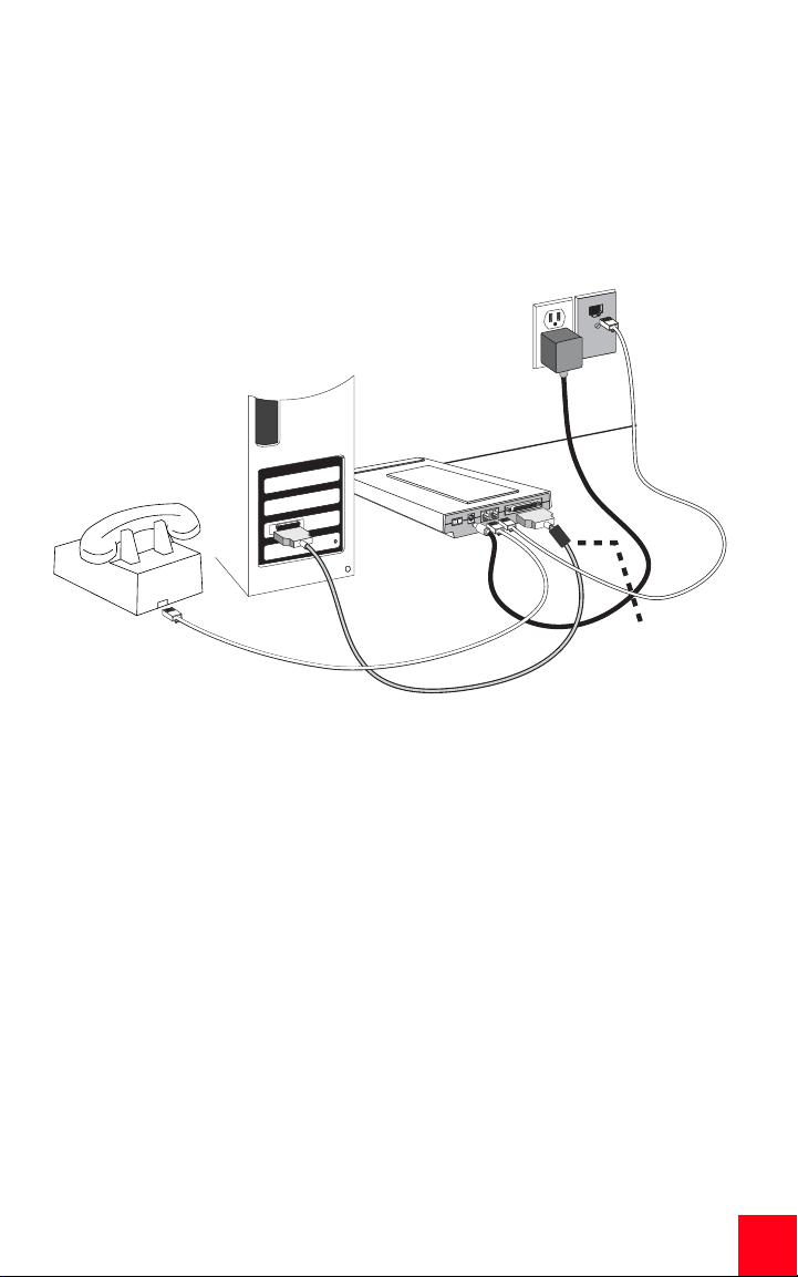
Step Two: Connecting the Cables
NOTE: If you plan to connect your Courier 56K Corporate Modem to a
mainframe computer or use your modem to dial in to a mainframe
computer, you will find more technical information on the Installation
CD-ROM that comes with your new modem.
1. Make sure that your computer is turned off before you begin installing your
new modem. Connect the RS-232 modem cable to the back of the modem
and to your computer’s serial port. Clip the ferrite clamp around the end of
the RS-232 cable that is connected to the modem.
To find the serial port on the back of your computer, look for COM, MODEM, RS232, IOIOI, or SERIAL. Do not use the AUX, GAME, LPT, or PARALLEL ports.
2. Plug one end of the included phone cord into the jack on the back of
the modem and plug the other end into an analog telephone wall jack. If
there is another phone jack on your modem, you can use a telephone by
plugging the telephone’s cord into the modem’s jack. Plug the power
adapter into the modem’s jack and into a surge protector or electrical
outlet. Make sure to use the power adapter that came with your modem,
as others may be of different voltages and could damage your modem.
Turn on the modem by pressing the button on the back of the modem. The
CTS and MR lights should illuminate.
3. If the CTS and MR lights do not illuminate or other lights illuminate, make
sure that only DIP switches 3, 5, and 8 are in the on (down) position. (The
5
Page 8

DIP switches are located on the bottom of the modem.)
Step Three: Installing the Drivers
Windows 95
Turn on your computer. When the Update Driver Wizard appears, insert your
Installation CD-ROM into your CD-ROM drive and click Next. When the driver is
found, click Finish to complete your installation.
Windows 98
Turn on your computer. When the Add New Hardware Wizard appears, insert
your Installation CD-ROM into your CD-ROM drive and click Next. Select Search
for the best driver for your device (Recommended) and click Next. Select CDROM drive and click Next. When the driver is located, click Next. Click Finish to
complete your installation.
Windows 2000
NOTE: Windows 2000 users must be in administrator mode to properly
add any new hardware.
Turn on your computer and log in. Windows will detect your new modem and
automatically install it, then you must update the driver. Insert the Installation
CD-ROM into your CD-ROM drive. Click Cancel to close the Setup Language
screen. Click Windows Start and Control Panel. Double-click System, click the
Hardware tab, and click the Device Manager button. Click to expand Modems,
and double-click Standard Modem. Click the Driver tab and click the Update
Driver button. When the Upgrade Device Driver window appears, click Next.
Select Search for a suitable driver for my device (recommended) and click Next.
Select Specify a location and click Next. Insert your Installation CD-ROM into
your CD-ROM drive. Click Cancel to close the Setup Language screen. Type the
letter of your CD-ROM drive and click OK. Click Next. A Digital Signature Not
Found warning may appear. If it does, click Yes*. Click Finish to complete the
installation.
Windows NT
NOTE: Windows NT users must be in administrator mode to properly
add any new hardware.
Turn on your computer and log in. Click Windows Start, point to Settings, and
then click Control Panel. Double-click Modems. When the Install New Modem
screen appears, click Next to have Windows detect a standard modem. Click
Change. Click Have Disk. Insert the Installation CD-ROM into your CD-ROM drive
6
Page 9
and click Cancel to close the Setup Language screen. Type D:\ and click OK. If
your CD-ROM drive uses a different letter, type that letter in place of “D”. Select
U.S. Robotics Courier V.Everything EXT and click OK. Click Next. Click Finish to
complete the installation. When you see the Modems Properties tab, you will see
the COM port that is assigned to your modem. Click Close. If the System Settings
Change window appears, click Yes to restart your computer. When the
installation is complete, you may close any open windows.
clip the ferrite
clamp around the
end of the RS-232
cable closest to
the modem
Windows Me
Turn on your computer and log in. Windows will detect your new modem and
automatically install it, then you must update the driver. Insert the Installation
CD-ROM into your CD-ROM drive. Click Cancel to close the Setup Language
screen. Click Windows Start, point to Settings, and click Control Panel. Doubleclick System. Click the Device Manager tab. Click Modem, highlight U.S.
Robotics Courier V.Everything EXT PnP. Click the Properties button. Click the
Driver tab and click the Update Driver button. Select Specify the location of the
driver (Advanced) and click Next. Select Search for a better driver than the one
your device is using now (Recommended). Select Specify a location and type
the letter of your CD-ROM drive. Insert the Installation CD-ROM into your CDROM drive and click Next. When Windows finds the driver, click Next. Click Finish
to complete the installation.
Windows XP
Turn on your computer. Windows will detect your new modem and automatically
install it, then you must update the driver. Insert the Installation CD-ROM into
your CD-ROM drive. Click Cancel to close the Setup Language screen. Click
Windows Start and Control Panel. Make sure you are in Classic View, and
double-click Phone and Modem Options. Click the Modems tab and click the
7
Page 10

Properties button. Click the Driver tab and click the Update Driver button. When
the Hardware Update Wizard appears, select Install from a list or specific
location (Advanced) and click Next. Select Don’t search. I will choose the driver
to install. Click Next. Click Have Disk. Insert the Installation CD-ROM into your
CD-ROM drive, type the letter of your CD-ROM drive, and click OK. Click to select
U.S. Robotics Courier V.Everything EXT PnP. Click Next. A Hardware Installation
warning may appear. Click Continue Anyway if it does*. Click Finish to complete
the installation.
All Other Operating Systems
Beyond full support of the Windows Operating Systems described in this
manual, the Courier 56K Corporate Modem will function in any operating system
that supports an RS-232 COM port, such as DOS, Linux, or UNIX. Standard COM
port settings are: bits per second: 115,200; data bits: 8; parity: none; stop bits:
1; flow control: hardware. Assign your terminal application to utilize the COM
port to which you connect the modem's serial cable. Additional setup
information can be found in the 3453 FAQ section at http://www.usr.com/
support
*U.S. Robotics has thoroughly tested this driver in conjunction with the supported hardware and has
verified compatibility with Windows XP and 2000.
Register your modem.
• At the Installation CD-ROM interface, click the Support link.
• Follow the on-screen instructions to register your modem and to view
the warranty information. Click Windows Start and then click Run. In
the “Run” dialogue box, type D:\setup.exe. If your CD-ROM drive uses
a different letter, type that letter in place of “D”.
Configuring V.Everything
NOTE: The modem needs to be installed and communicating with the
computer before the country setting can be changed.
Start a terminal program (e.g., Hyperterminal). Follow these three steps:
1. Type the AT command AT~C? and then press ENTER. A screen displaying
the list of countries supported by the modem appears as shown in the following list.
2. Select the country in which you plan to operate the modem and enter the
AT command ATC10=XX. For example, to set the country of operation to
8
Page 11

Italy, issue the AT command ATC10=03 and then press ENTER.
00:US/Canada 01:UK
02:Germany 03:Italy
04:France 05:Russia
06:Japan 07:Australia
08:CTR21 09:Brazil
10:China 11:Czech Rep
12:Hong Kong 13:Hungary
14:Indonesia 15:Korea
16:Malaysia 17:Mexico
18:New Zealand 19:Poland
20:Romania 21:Singapore
22:South Africa 23:Taiwan
24:Argentina 25:India
26:Bulgaria 27:CTR21
Special Notes
• CTR21 country setting covers: Austria, Belgium, Cyprus, Denmark, Fin-
land, Greece, Iceland, Ireland, Israel, Liechtenstein, Luxembourg,
Netherlands, Norway, Portugal, Spain, Sweden, Switzerland, Malta.
• If the desired country is not included in this list, try country setting
CTR21 or US/Canada.
• For LATIN AMERICAN countries: Brazil and Mexico have unique set-
tings. For other Latin American countries, select US/Canada as the
country setting.
3. Type the AT command ATI7 and then press ENTER to verify the country setting for the modem. A response similar to the following appears:
Product type US/Canada External
Product ID 00345301
Options HST,V32bis,Terbo,VFC,V34+,V90,V92
Fax Options Class 1,Class 2.0
Clock Freq 25 Mhz
Flash ROM 1024k
9
Page 12

Product type US/Canada External
RAM 256k
Supervisor date 10/10/02
DSP date
Supervisor rev
DSP rev
DAA rev
Serial Number xxxxxxxxxxxx
The “Product type” field shows the current country setting of the modem.
Repeat the above steps to select a different country of operation.
09/19/02
1.1.11
1.3.1
0012
Viewing LEDs
This LED Status Means your Courier 56K Corporate Modem
HS On Has made a 4800 bps or faster connection. Once this light
is on, it remains on until reset. This can be configured with
S69 (see the Command Reference on the Installation CDROM for S-Register information).
Off Has not made a 4800 bps or faster connection since last
reset
AA On Is ready to accept calls
Blinking Has detected an incoming call
Off Is not ready to accept calls
CD On Has detected a carrier from a remote device or carrier
detect has been forced on (using DIP switch 6)
Off Has not detected a carrier
OH On Has control of the line
Off Does not have control of the line
RD Flashing Is sending data to your computer
Off Is idle
SD Flashing Is receiving data from your computer
Off Is idle
DTR On Has received a Data Terminal Ready (DTR) signal from
Off Has not detected DTR
your computer, or DTR is forced on (using DIP switch 1)
10
Page 13

This LED Status Means your Courier 56K Corporate Modem
MR On Is powered on
Flashing Is retraining with a remote device or is in Test mode
Off Is powered off
RTS On Has detected the Ready to Send (RTS) signal from your
computer
Off Has not detected the RTS signal from your computer
CTS On Is sending your computer the Clear to Send (CTS) signal
Off Is not sending your computer the CTS signal
SYN On Is in synchronous mode
Blinking Has activated Dial Security
Off Is not in synchronous mode/Dial Security not active
ARQ/FAX On Is using V.42 bis error correction
Flashing Is retransmitting data to the remote modem
Blinking Is in fax mode
Off Is not using error control, not retransmitting data, and not
faxing
Configuring the Courier 56K Corporate Modem with DIP Switches
Locating DIP Switches
On the Courier 56K Corporate Modem, the DIP switches are on the bottom of the
unit. The default setting is DIP switches 3, 5, and 8 are ON (in the down position).
DIP Switches
11
Page 14

Using DIP Switches to Configure your Courier V.Everything Modem
To do this Set DIP Switch To this setting
Set DTR to Normal 1 OFF (Default)
Ignore DTR 1 ON
Set verbal result code display 2 OFF (Default)
Set numeric result code display 2 ON
Disable result codes 3 OFF
Enable result codes 3 ON (Default)
Enable the echo in offline commands 4 OFF (Default)
Disable the echo in offline commands 4 ON
Enable auto answer 5 OFF
Disable auto answer 5 ON (Default)
Normal Carrier Detect 6 OFF (Default)
Carrier Detect always on 6 ON
Display result codes In ALL modes 7 OFF (Default)
Display result codes in originate mode only 7 ON
Disable AT commands 8 OFF
Enable AT commands 8 ON (Default)
Disconnect on escape (+++) 9 OFF (Default)
Online command mode on escape (+++) 9 ON
Load the configuration that is stored in non-volatile memory (NVRAM)
Load the &F0 configuration from read-only
memory (ROM)
10 OFF (Default)
10 ON
12
Page 15

Troubleshooting
Having trouble with your modem? Try these basic troubleshooting steps first!
1. Is your modem turned on? When your modem is properly connected to an
electrical outlet, a wall outlet, or a surge protector and is turned on, the
CTS and MR lights on the front panel will be illuminated.
2. Is your power supply connected properly to both your modem and an electrical outlet? If it is, check the outlet with another electric device (like a
lamp) to be sure that you are getting power. Also, use the power supply
that came with your modem; other similar-looking power supplies may be
of different voltages and could damage your modem.
3. Are you using the proper cable to connect your modem to your computer?
Make sure you are using an RS-232 modem cable, preferably the one that
came with your modem. There are many computer cables that look similar
to an RS-232 that will not work correctly with this modem. For example, a
Null Modem cable will not work with your modem. Depending on whether
you have a 9-pin or 25-pin serial port on your computer, you will need
either a DB9/DB25 or a DB25/DB25 serial cable.
4. For standard usage, make sure the DIP switches on the bottom of your
modem are set correctly. DIP switches 3, 5, and 8 should be in the on
(down) position. See the diagram in the DIP Switch section in this manual
for the proper settings.
5. Is your phone cord properly connected? The phone cord should be plugged
into the jack on the modem and into the telephone wall jack. Use the
phone cord included in your modem’s box, if possible.
If you have any difficulty with your modem, first make sure that it was installed correctly.
Windows XP
•Click Windows Start and then click Control Panel.
• Click Phone and Modem Options and then click the Modems tab.
You should see a description of your new U.S. Robotics modem and a
COM port setting. If you do not see a description of your modem,
see the Note at the end of this section.
• Click Modem, highlight the description of your new modem, and
click Properties.
• Click the Diagnostics tab.
•Click the Query Modem button. You should see a series of commands
and responses from the modem. This means that the installation was
13
Page 16

a success. If you do not see commands and responses, shut down and
restart your computer. To determine if your modem is functioning
properly, repeat the steps above. If your modem is still not working,
refer to the additional troubleshooting in this guide.
Windows 2000
•Click Windows Start, Settings, and then Control Panel.
• Double-click the Phone and Modem Options icon.
• Click the Modems tab. Make sure that your new U.S. Robotics
modem is selected. If you do not see a description of your modem,
see the Note at the end of this section.
•Click the Properties button.
• Click the Diagnostics tab.
•Click the Query Modem button. You should see a series of commands
and responses from the modem. This means that the installation was
a success. If you do not see commands and responses, shut down and
restart your PC. To determine if your modem is functioning properly,
repeat the steps above. If your modem is still not working, refer to the
additional troubleshooting in this guide.
Windows Me, 98, 95
•Click Windows Start, Settings, and then Control Panel.
• Double-click the Modems icon. In the Modems Properties screen,
you should see a description for your new U.S. Robotics modem. If
you do not see a description of your modem, see the Note at the
end of this section.
• Click the Diagnostics tab. Make sure that the correct COM port
(modem) is selected.
•Click the More Info button. You should see a series of commands
and responses from the modem. This means that the installation was
a success. If you do not see commands and responses,
shut down and restart your PC. To determine if your modem is
functioning properly, repeat the steps above. If your modem is still not
working, refer to the additional troubleshooting in this
guide.
14
Windows NT
•Click Windows Start, Settings, and then Control Panel.
• Double-click the Modems icon. In the Modems Properties screen,
you should see a description for your new U.S. Robotics modem. If
you do not see commands and responses, shut down and restart
your PC. To determine if your modem is functioning properly,
repeat the steps above. If your modem is still not working, refer to the
additional troubleshooting in this guide.
Page 17

NOTE: If your modem is not listed and/or you do not see a series of
commands and responses, make sure that your cables are attached
correctly to your computer. If your modem still does not work, refer to
the additional troubleshooting section of this guide. Shut down and restart your
computer. To verify that your modem is functioning properly, repeat the steps
listed for your operating system.
For additional troubleshooting help, review these common issues:
My computer isn’t recognizing my modem.
Possible solution: You may be using a COM port that is either already in use
or not configured correctly. For the modem to work properly, it must be
plugged into an enabled serial port which is assigned to a free COM port.
Most computers have two serial ports assigned to COM 1 and COM 2
respectively.
Windows XP, 2000
Make sure your COM port is not already in use by another modem. Click
Windows Start, Settings (for Windows 2000 only), and Control Panel, and
then double-click Phone and Modem Options. Click the Modems tab. Look
for a listed modem and check which COM port it is using. If a previous
modem is already using the available COM port, you can either use another
COM port or uninstall the modem that was installed previously. See your
previous modem’s manual for uninstallation instructions. Next make sure
that your COM ports are configured correctly. Right-click the My Computer
icon on your desktop. Click Properties. Click the Hardware tab. In the
“Device Manager” section, click the Device Manager button. Look under
Ports (COM and LPT). If the Communications ports have yellow exclamation
points or red Xs over them, your COM ports may be configured incorrectly.
If this is the case, you may need to contact your computer manufacturer. It
is also possible that you may be plugging your external modem’s cable into
a disabled serial port. Refer to your computer’s manual for information
about enabling COM ports. This usually involves altering the BIOS settings
and possibly the operating system. You may need to call your computer’s
manufacturer to change your BIOS settings if they are incorrect.
Windows Me, 98, 95
Make sure your COM port is not already in use by another modem. Click
Windows Start, Settings, and Control Panel, and then double-click
Modems. If you have Windows Me and you do not see this icon, be sure to
select View All Control Panel Options. Look for another modem listed and
if another modem is listed, click the Diagnostics tab to find out which COM
15
Page 18

port it is using. If a previous modem is already using the available COM port,
you can either use another COM port or uninstall the previously installed
modem. See your previous modem’s manual for uninstallation instructions.
Next, make sure that your COM ports are configured correctly. Right-click
the My Computer icon on your desktop. Click Properties. Click the Device
Manager tab. Look under Ports (COM and LPT). If the COM ports have
yellow exclamation points or red Xs over them, your COM ports may be
configured incorrectly. If this is the case and you are not sure how to
properly configure your COM ports, contact your computer manufacturer.
It is also possible that you may be plugging your RS-232 modem cable into
a disabled serial port. Refer to your computer’s manual for information
about enabling COM ports. This usually involves altering the BIOS settings
and possibly the operating system. You may need to call your computer’s
manufacturer to change your BIOS settings if they are incorrect.
Windows NT
Click Windows Start, Settings, and then Control Panel. Double-click Ports.
Make sure the port you are plugging the modem into appears in the list. If
it does not, the port needs to be added, and possibly enabled in the BIOS.
Consult your Windows NT manual for information about adding ports. After
you add or enable the port, follow the instructions in this guide for your
operating system.
My software isn’t recognizing my modem.
16
Possible solution: Your communications software may not function
properly if you have more than one version of the software installed or if you
are using an older version. We highly recommend using the
communications software provided with your modem on the Installation
CD-ROM.
Possible solution: Make sure the modem is plugged in and turned on. If it
is, check the outlet with another electric device (like a lamp) to be sure that
you are getting power. Also, you must use the power supply that came with
your modem; other similar-looking power supplies may be of different
voltages and could damage your modem. When your modem is properly
connected to an electrical outlet, a wall outlet, or a surge protector and is
turned on, the CTS and MR lights on the front panel will be illuminated.
Windows XP, 2000
You may not have the correct modem type selected in your software or in
Windows. Click Windows Start, Settings (Windows 2000 only), and then
Control Panel. When Control Panel opens, click Phone and Modem Options.
Click the Modems tab. Here you will see a list of installed modems. You can
Page 19

also add, remove, or view the properties of modems from this window. The
U.S. Robotics modem you have installed should be present in the list of
installed modems. If none of the modem descriptions in the list matches
your U.S. Robotics modem or no modems are listed, your modem is not
properly installed. Try reinstalling your modem using the instructions on
this guide for your operating system.
Windows Me, 98, 95, NT
You may not have the correct modem type selected in your software or in
Windows. Click Windows Start, Settings, and Control Panel. When Control
Panel opens, double-click Modems. Here you will see a list of installed
modems. You can also add, remove, or view the properties of modems from
this window. The U.S. Robotics modem you have installed should be
present in the list of installed modems. If none of the modem descriptions
in the list matches your U.S. Robotics modem or no modems are listed, your
modem is not properly installed. Try reinstalling your modem using the
instructions in this guide for your operating system.
Windows XP
If you are using Dial-Up Networking, it may not be configured correctly.
Check your configuration and make sure you have the correct port selected.
Click Windows Start, Control Panel, and double-click Network Connections.
Double-click the description of the dial-up networking connection, and
select Properties. Make sure that the description in the “Connect Using”
box (under the General tab) matches the description of the modem you are
using. If it doesn’t match, select the proper modem description.
Windows 2000
If you are using Dial-Up Networking, it may not be configured correctly.
Check your configuration and make sure you have the correct port selected.
Click Windows Start, point to Settings, and click Network and Dial-up
Connections. Make sure that the description in the “Connect Using” box
(under the General tab) matches the description of the modem you are
using. If it doesn’t match, select the proper modem description.
Windows Me, 98, 95, NT
If you are using Dial-Up Networking, it may not be installed or configured
correctly. Check your configuration and make sure you have the correct port
selected. Double-click My Computer, double-click Dial-Up Networking,
right-click the connection you are trying to use, and select Properties. Make
sure that the description in the modem box matches the description of the
modem you are using. If it doesn’t match, select the proper modem
description.
17
Page 20

My modem is responding but is reporting a No Dial Tone message.
Possible Solution: Make sure that you are using the power supply that
came with your modem. Other similar-looking power supplies may be of
different voltages, and in addition to possibly causing damage to the
modem, they may not allow the modem to dial out.
Possible Solution: Your phone cord may not be plugged in or may be
plugged into the wrong jack on the modem.
Possible Solution: Make sure the other end of the phone cord is plugged
into a working analog phone jack in your home or office.
Possible Solution: You may have devices between the modem and wall jack
that affect the quality of your phone line. If you need to connect other
devices to your phone line and want to ensure the best quality line for your
modem, connect the phone cord directly from the wall to your modem.
Possible Solution: Make sure the phone line you are using is not a digital
line. Digital phone lines can damage your modem. If you are unsure which
type of line you are using, you may want to call your local phone company.
In an office environment, you may need to contact the person in charge of
your phone system to find out which type of phone line you have.
Possible Solution: If your phone system requires dialing a digit such as “9”
in order to access an outside line, be sure to add the digit and a comma (9,)
before the number you want to dial.
Possible Solution: If you have voice mail provided by your phone company,
your dial tone may be altered when messages are waiting. Retrieve your
voice mail to restore a normal dial tone. If you are unable to retrieve the
messages, you may want to add five commas to the beginning of the
number to be dialed.
NOTE: Each comma represents two seconds. Therefore, adding five
commas will delay the modem connection attempt by 10 seconds. Since
each ISP connection may vary, you should insert as many commas as
necessary to meet your specific needs. Commas may be necessary if voice mail
messages have not been deleted before attempting to establish an Internet
connection.
Possible Solution: Be sure you have the correct country code selected for
your modem. See the “Configuring V.Everything” section of this guide for
instructions.
18
Page 21

Possible Solution: You may have a bad phone cord connection to the
modem. Try the modem with a different phone cord. We recommend that
you use the phone cord included with the modem, if possible.
How to Check for a Non-standard Dial Tone
1. Open a terminal program, such as HyperTerminal, in Windows.
2. Select Cancel at the new connection dialogue box to open the Terminal
window.
3. Type AT and press ENTER. You may not see the letters, which is fine.
4. The modem should respond with an OK message. If you did not see the let-
ters A and T as you typed them, type ATE1 and press ENTER. You should
now see the AT commands as you type them, in addition to the responses.
5. Type ATDT and press ENTER.
6. If the modem comes back with a No Dial Tone message, type the phone
number of a local ISP (Internet Service Provider) or BBS number and press
ENTER.
NOTE: The number in the command code is the actual number to be
dialled.
7. If the modem dials out instead of coming back with a No Dial Tone mes-
sage, you have a non-standard dial tone. At this point you should either
have your phone line checked or try adding X3 to the Extra Settings field.
Access Extra Settings for help locating the Extra Settings field specific to
your operating system.
8. If the modem doesn't attempt to connect and it comes back with a No Car-
rier message, the issue may not be phone line related.
Closing the window to end your HyperTerminal session.
• Select No when the Are you sure you want to disconnect? message
appears. Select Yes when the Are you sure you want to save this
session? message appears.
My modem won’t dial out or doesn’t answer incoming calls.
Possible solution: Make sure that you are using the power supply that came
with your modem; other similar-looking power supplies may be of different
19
Page 22

voltages and could damage your modem.
Possible solution: You might have a bad phone cord connected to your
modem, or your phone cord may be plugged into the wrong jack. The phone
cord should be plugged into the jack labelled on the modem and into
the telephone wall jack. Use the phone cord included in your modem’s box,
if possible.
Possible solution: You may have devices between the modem and the
phone jack. There should be no line splitters, fax machines, or other devices
between the modem and the telephone wall jack.
Office Users
Possible solution: You may have plugged your modem’s phone cord into a
digital line, which can damage your modem. Contact your phone system
administrator if you are unsure whether or not your phone line is digital.
If your phone system requires dialing “9” to access an outside line, be sure
to add “9” before the number you are dialing.
Dialing Problems for Voice Mail Users
Possible solution: If you have voice mail provided by your local phone
company, your dial tone may be altered when messages are waiting.
Retrieve your voice mail to restore your normal dial tone.
My modem sounds like it’s trying to connect to another modem but fails.
Possible solution: You may have a poor connection. All calls are routed
differently, so try placing the call again.
Possible solution: Make sure that the DIP switches on the bottom of your
modem are set correctly. DIP switches 3, 5, an d 8 s ho uld be in t he on ( do wn)
position. See the diagram in the “Configuring the Courier 56K Corporate
Modem with DIP Switches” section in this guide for the correct settings.
My modem isn’t achieving a 56K Internet connection.
Possible solution: Our research has shown that the vast majority of
telephone lines can and do support V.90 connections. The V.90 protocol
allows for connection speeds of up to 56K, but line conditions may affect
the actual speeds during a given connection. Due to unusual telephone line
configurations, some users will not be able to take full advantage of V.90
20
Page 23

technology at this time. In order to achieve a V.90 connection:
1. The server you are dialing into must support and provide a digital V.90 signal. Your ISP can provide you with a list of dial-up connections and information on what those connections currently support.
2. The telephone line between your ISP and your modem must be capable of
supporting a 56K connection and contain only one analog-to-digital conversion. The 56K signal from your ISP begins as a digital signal. Somewhere between the ISP and your modem, there will be a digital-to-analog
signal conversion so that your modem can receive the data. There must be
no more than one analog-to-digital signal conversion in the path from your
ISP to your modem. If more than one analog-to-digital conversion occurs,
your connection speeds will default to V.34+ (33.6 Kbps). There may also
be impairments on the local lines between your ISP and your modem.
These impairments can prevent or limit connection speeds. All telephone
calls are routed differently, so you should try making your 56K connection
several times. One way to test this is to dial into a long distance location.
Long distance lines are often much clearer than local lines. It is important
to note that telephone companies are constantly upgrading their systems.
Lines that do not support 56K today may support 56K in the near future.
3. For a V.90 connection, your modem must be connecting to a V.90/56K
server. A pair of 56K modems will not connect to each other at V.90/56K
speeds.
Support Resources
If you have not fixed your problem after trying the suggestions in the
“Troubleshooting” section of this guide, you can receive additional help via one
of these convenient resources:
1. Visit the U.S. Robotics Web site
Many of the most common difficulties users experience have been
addressed in the FAQ and Troubleshooting Web pages for your specific
product. Your product ID is USRxx3453. You may need to know this to
obtain information on the U.S. Robotics Web site. Go to:
http://www.usr.com/support
2. Contact the U.S. Robotics Technical Support Department
Technical questions about U.S. Robotics modems can also be answered by
technical support specialists.
United
States
(888) 3266099
http://www.usr.com/emailsupport 9:00 A.M.– 5:00 P.M.
CST Monday – Friday
21
Page 24

For regions not listed or for the most current support contact information, visit
http://www.usr.com/international.asp
Manufacturer’s Declaration of Conformity
U.S. Robotics Corporation
935 National Parkway
Schaumburg, IL 60173-5157
U.S.A.
declares that this product conforms to the FCC’s specifications:
Part 15, Class B:
Operation is subject to the following conditions:
1) this device may not cause harmful electromagnetic
interference, and
2) this device must accept any interference received including interference that may cause undesired
operations.
This equipment complies with Part 15 for Home and Office use.
Caution to the User:
The user is cautioned that any changes or modifications not expressly approved by the party
responsible for compliance could void the user’s authority to operate the equipment.
Part 68:
This equipment complies with FCC Rules Part 68. Located on the bottom of the modem is the FCC
Registration Number and Ringer Equivalence Number (REN). You must provide this information to the
telephone company if requested.
The REN is used to determine the number of devices you may legally connect to your telephone line. In
most areas, the sum of the REN of all devices connected to one line must not exceed five. You should
contact your telephone company to determine the maximum REN for your calling area.
This equipment may not be used on coin service provided by the telephone company. Connection to
party lines is subject to state tariffs.
An FCC compliant telephone cord and modular plug are provided with this equipment, which is
designed to connect to the telephone network or premises wiring using a Part 68 compliant compatible
jack. See installation instructions for details. This equipment uses the following USOC jacks: RJ-11C.
UL Listing/CUL Listing
This information technology equipment is UL-Listed and CUL-Listed for both the U.S. and Canadian
markets respectively, for uses described in this guide.
Fax Branding:
The Telephone Consumer Protection Act of 1991 makes it unlawful for any person to use a computer or
other electronic device, including fax machines, to send any message unless such message clearly
contains in the margin at the top or bottom of each transmitted page or on the first page of the
transmission, the date and time it is sent, an identification of the business or other entity, or other
individual sending the message, and the telephone number of the sending machine or of such business,
other entity, or individual. (The telephone number provided may not be a 900 number or any other
number for which charges exceed local or long-distance transmission charges.) In order to program this
information into your modem, refer to the software on the CD-ROM that shipped with your modem. If
you are using a different communication software program, refer to its manual.
Radio and Television Interference:
This equipment generates, uses, and can radiate radio frequency energy. If this equipment is not
installed and used in accordance with the manufacturer’s instructions, it may cause interference to
radio and television communications. The modem has been tested and found to comply with the limits
for a Class B computing device in accordance with the specifications in Part 15 of FCC rules, which are
designed to provide reasonable protection against such interference in a residential installation.
For Canadian Modem Users
Industry Canada (IC)
This digital apparatus does not exceed the Class B limits for radio noise emissions from digital
22
Page 25

apparatus set out in the interference-causing equipment standard entitled Digital Apparatus, ICES-003
of Industry Canada.
NOTICE: The Ringer Equivalence Number (REN) assigned to each terminal device provides an indication
of the maximum number of terminals allowed to be connected to a telephone interface. The termination
on an interface may consist of any combination of devices subject only to the requirement that the sum
of the Ringer Equivalence Numbers of all devices does not exceed 5. The Ringer Equivalence Number is
located on the bottom of the modem.
NOTICE: The Industry Canada (IC) label identifies certified equipment. This certification means the
equipment meets certain telecommunications network protective, operational, and safety
requirements as prescribed in the appropriate Terminal Equipment Technical Requirements
document(s). The Department does not guarantee the equipment will operate to the user’s satisfaction.
Before installing this equipment, users should ensure that it is permissible to be connected to the
facilities of the local telecommunications company. The equipment must also be installed using an
acceptable method of connection. In some cases, the company’s inside wiring associated with a singleline, individual service may be extended by means of a certified connector assembly (telephone
extension cord). The customer should be aware that compliance with the above conditions may not
prevent degradation of service in some situations. Currently, telecommunication companies do not
allow users to connect their equipment to jacks except in precise situations that are spelled out in
tariffing arrangements with those companies. Repairs to certified equipment should be coordinated by
a representative designated by the supplier. Any repairs or alterations made by the user to this
equipment, or equipment malfunctions, may give the telecommunications company cause to request
the user to disconnect the equipment.
«AVIS: Cet appareil numérique respecte les limites de bruits radioélectriques applicables aux appareils
numériques de classe B prescrites dans la norme sur le matériel brouilleur: “Appareils Numériques”,
NMB-003 édictée par l’Industrie Canada.
L’étiquette d’Industrie Canada identifie le matériel homologué. Cette étiquette certifie que le matériel
est conforme aux normes de protection, d’exploitation et de sécurité des réseaux de
télécommunications, comme le prescrivent les documents concernant les exigences techniques
relatives au matériel terminal. Le Ministère n’assure toutefois pas que le matériel fonctionnera à la
satisfaction de l’utilisateur.
Avant d’installer ce matériel, l’utilisateur doit s’assurer qu’il est permis de le raccorder aux installations
de l’entreprise locale de télécommunication. Le matériel doit également être installé en suivant une
méthode acceptée de raccordement. L’abonné ne doit pas oublier qu’il est possible que la conformité
aux conditions énoncées cidessus n’empêche pas la dégradation du service dans certaines situations.
Les réparations de matériel homologué doivent être coordonnées par un représentant désigné par le
fournisseur. L’entreprise de télécommunications peut demander à l’utilisateur de débrancher un
appareil à la suite de réparations ou de modifications effectuées par l’utilisateur ou à cause de
mauvaisfonctionnement. Centre de guarantie et de service après-vente:
U.S. Robotics
Unit-100, 13751 Mayfield Pl.
Richmond, B.C. Canada V6V 2G9
CE Compliance
We, U.S. Robotics Corporation of 935 National Parkway, Schaumburg, Illinois, 60173-5157 USA, declare
under our sole responsibility that the product, Courier 56K Corporate Modem, to which this declaration
relates, is in conformity with the following standards and/or other normative documents.
EN60950
EN55022
EN55024
EN61000-3-2
EN61000-3-3
We hereby declare that the above named product is in compliance with all the essential requirements
23
Page 26

and other relevant provisions of Directive 1999/5/EC.
The conformity assessment procedure referred to in Article 10(3) and detailed in Annex II of Directive
1999/5/EC has been followed.
Network Compatibility Declaration
This equipment is designed to work satisfactorily on all European Union PSTN networks.
This equipment is supplied with a suitable PSTN connector for the country in which it was supplied. If it
is required to use this equipment on a different network to the one for which it was supplied, the user
is advised to contact the vendor for guidance regarding connection.
U.S. Robotics Corporation
935 National Parkway
Schaumburg, Illinois, 60173
U.S.A
U.S. Robotics Corporation Limited Manufacturer’s Warranty
Courier 56K Corporate Modem
HARDWARE: U.S. Robotics warrants to the end user (“Customer”) that this hardware product will be
free from defects in workmanship and materials, under normal use and service, for the following length
of time from the date of purchase from U.S. Robotics or its authorised reseller:
Limited Lifetime
U.S. Robotics’s sole obligation under this express warranty shall be, at U.S. Robotics’s option and
expense, to repair the defective product or part, deliver to Customer an equivalent product or part to
replace the defective item, or if neither of the two foregoing options is reasonably available, U.S.
Robotics may, in its sole discretion, refund to Customer the purchase price paid for the defective
product. All products that are replaced will become the property of U.S. Robotics. Replacement
products may be new or reconditioned. U.S. Robotics warrants any replaced or repaired product or part
for ninety (90) days from shipment, or the remainder of the initial warranty period, whichever is longer.
SOFTWARE: U.S. Robotics warrants to Customer that each software program licensed from it will
perform in substantial conformance to its program specifications, for a period of ninety (90) days from
the date of purchase from U.S. Robotics or its authorized reseller. U.S. Robotics warrants the media
containing software against failure during the warranty period. No updates are provided. U.S.
Robotics’s sole obligation under this express warranty shall be, at U.S. Robotics’s option and expense,
to refund the purchase price paid by Customer for any defective software product, or to replace any
defective media with software which substantially conforms to applicable U.S. Robotics published
specifications. Customer assumes responsibility for the selection of the appropriate applications
program and associated reference materials. U.S. Robotics makes no warranty or representation that
its software products will meet Customer’s requirements or work in combination with any hardware or
applications software products provided by third parties, that the operation of the software products
will be uninterrupted or error free, or that all defects in the software products will be corrected. For any
third-party products listed in the U.S. Robotics software product documentation or specifications as
being compatible, U.S. Robotics will make reasonable efforts to provide compatibility, except where the
non-compatibility is caused by a “bug” or defect in the third party's product or from use of the software
product not in accordance with U.S. Robotics published specifications or user manual.
THIS U.S. ROBOTICS PRODUCT MAY INCLUDE OR BE BUNDLED WITH THIRD-PARTY SOFTWARE, THE USE
OF WHICH IS GOVERNED BY A SEPARATE END USER LICENSE AGREEMENT. THIS U.S. ROBOTICS
WARRANTY DOES NOT APPLY TO SUCH THIRD-PARTY SOFTWARE. FOR THE APPLICABLE WARRANTY,
PLEASE REFER TO THE END USER LICENSE AGREEMENT GOVERNING THE USE OF SUCH SOFTWARE.
OBTAINING WARRANTY SERVICE: Customer must contact a U.S. Robotics Corporate Service Centre or
an Authorized U.S. Robotics Service Centre within the applicable warranty period to obtain warranty
service authorization. Dated proof of purchase from U.S. Robotics or its authorized reseller may be
required. Products returned to U.S. Robotics Corporate Service Centre must be pre-authorized by U.S.
Robotics with a Return Material Authorization (RMA) number or User Service Order (USO) number
24
Page 27

marked on the outside of the package, and sent prepaid and packaged appropriately for safe shipment,
and it is recommended that they be insured or sent by a method that provides for tracking of the
package. Responsibility for loss or damage does not transfer to U.S. Robotics until the returned item is
received by U.S. Robotics. The repaired or replaced item will be shipped to Customer, at U.S. Robotics’s
expense, not later than thirty (30) days after U.S. Robotics receives the defective product.
U.S. Robotics shall not be responsible for any software, firmware, information, or memory data of
Customer contained in, stored on, or integrated with any products returned to U.S. Robotics for repair,
whether under warranty or not.
WARRANTIES EXCLUSIVE: IF A U.S. ROBOTICS PRODUCT DOES NOT OPERATE AS WARRANTED ABOVE,
CUSTOMER'S SOLE REMEDY FOR BREACH OF THAT WARRANTY SHALL BE REPAIR, REPLACEMENT, OR
REFUND OF THE PURCHASE PRICE PAID, AT U.S. ROBOTICS’S OPTION. TO THE FULL EXTENT ALLOWED
BY LAW, THE FOREGOING WARRANTIES AND REMEDIES ARE EXCLUSIVE AND ARE IN LIEU OF ALL OTHER
WARRANTIES, TERMS, OR CONDITIONS, EXPRESS OR IMPLIED, EITHER IN FACT OR BY OPERATION OF
LAW, STATUTORY OR OTHERWISE, INCLUDING WARRANTIES, TERMS, OR CONDITIONS OF
MERCHANTABILITY, FITNESS FOR A PARTICULAR PURPOSE, SATISFACTORY QUALITY,
CORRESPONDENCE WITH DESCRIPTION, AND NON-INFRINGEMENT, ALL OF WHICH ARE EXPRESSLY
DISCLAIMED. U.S. ROBOTICS NEITHER ASSUMES NOR AUTHORIZES ANY OTHER PERSON TO ASSUME
FOR IT ANY OTHER LIABILITY IN CONNECTION WITH THE SALE, INSTALLATION, MAINTENANCE, OR USE
OF ITS PRODUCTS.
U.S. ROBOTICS SHALL NOT BE LIABLE UNDER THIS WARRANTY IF ITS TESTING AND EXAMINATION
DISCLOSE THAT THE ALLEGED DEFECT OR MALFUNCTION IN THE PRODUCT DOES NOT EXIST OR WAS
CAUSED BY CUSTOMER'S OR ANY THIRD PERSON'S MISUSE, NEGLECT, IMPROPER INSTALLATION OR
TESTING, UNAUTHORIZED ATTEMPTS TO OPEN, REPAIR, OR MODIFY THE PRODUCT, OR ANY OTHER
CAUSE BEYOND THE RANGE OF THE INTENDED USE, OR BY ACCIDENT, FIRE, LIGHTNING, POWER CUTS
OR OUTAGES, OTHER HAZARDS, OR ACTS OF GOD.
LIM ITAT ION O F LIA BILI TY. T O THE FULL EXTE NT AL LOW ED BY LAW, U.S. ROBOT ICS ALSO EXCL UDES FOR
ITSELF AND ITS SUPPLIERS ANY LIABILITY, WHETHER BASED IN CONTRACT OR TORT (INCLUDING
NEGLIGENCE), FOR INCIDENTAL, CO NSEQUENTIAL, INDIRECT, SPECIAL, OR PUNITIVE DAMAGES OF ANY
KIND, OR FOR LOSS OF REVENUE OR PROFITS, LOSS OF BUSINESS, LOSS OF INFORMATION OR DATA,
OR OTHER FINANCIAL LOSS ARISING OUT OF OR IN CONNECTION WITH THE SALE, INSTALLATION,
MAINTENANCE, USE, PERFORMANCE, FAILURE, OR INTERRUPTION OF ITS PRODUCTS, EVEN IF U.S.
ROBOTICS OR ITS AUTHORIZED RESELLER HAS BEEN ADVISED OF THE POSSIBILITY OF SUCH DAMAGES,
AND LIMITS ITS LIABILITY TO REPAIR, REPLACEMENT, OR REFUND OF THE PURCHASE PRICE PAID, AT
U.S. ROBOTICS’S OPTION. THIS DISCLAIMER OF LIABILITY FOR DAMAGES WILL NOT BE AFFECTED IF ANY
REMEDY PROVIDED HEREIN SHALL FAIL OF ITS ESSENTIAL PURPOSE.
DISCLAIMER: Some countries, states, or provinces do not allow the exclusion or limitation of implied
warranties or the limitation of incidental or consequential damages for certain products supplied to
consumers, or the limitation of liability for personal injury, so the above limitations and exclusions may
be limited in their application to you. When the implied warranties are not allowed to be excluded in
their entirety, they will be limited to the duration of the applicable written warranty. This warranty gives
you specific legal rights which may vary depending on local law.
GOVERNING LAW: This Limited Warranty shall be governed by the laws of the State of Illinois, U.S.A.
excluding its conflicts of laws principles and excluding the United Nations Convention on Contracts for
the International Sale of Goods.
U.S. Robotics Corporation
935 National Parkway
Schaumburg, Illinois, 60173
U.S.A
25
Page 28

26
Page 29

Page 30

Printed in XXXXXXXXXXXXXXXXXXXX
 Loading...