

Page 1

Winmodem 33600 & x2/56K*
User’s Manual
Page 2

* Depending on line conditions.
U.S. Robotics and the U.S. Robotics logo are 3Com registered
trademarks. IBM, IBM PC, PC/XT and PC/AT are International
Business Machines Corporation trademarks. Microcom
Networking Protocol (MNP) is a Microcom Inc. registered
trademark.
© 1997
Page 3

Table of Contents
Introduction 1
How a Modem Works..............................................1
How Does Your Sportster Winmodem 33600 & x2/56K
Work ?...................................................................2
Other Features.......................................................3
Package Contents...................................................4
Installation 5
Sportster Winmodem 33600 & x2/56K Installation......5
STEP 1: Insert the Modem Into the Computer ......6
STEP 2: Run the Modem’s Installation Program....8
STEP 3: Installing the Communications Software 11
Changing Country Setup under Windows 95 13
Using the Modem 15
Installation Test.....................................................15
Factory Settings...............................................16
Resetting the Modem to Factory Settings........... 17
Remarks on Using the Modem ............................... 18
Un-Installing the Modem ........................................19
Troubleshooting 21
Problems and Solutions.........................................21
If You Are Still Having Problems.............................31
Page 4

Voice Functions 33
Overview of Voice Functions.................................. 33
Speakerphone ...................................................... 34
Implementing Voice Functions................................34
Voice Applications............................................34
Application Settings..........................................34
Appendix A – Technical Reference 37
Main AT commands...............................................37
Appendix B – Technical Specifications 57
Sportster Winmodem 33600 & x2/56K
Specifications ....................................................... 57
Electrical power.................................................... 58
CE Mark...............................................................59
Electromagnetic Compatibility............................ 59
Safety ............................................................. 59
Glossary 61
Limited Warranty 69
Page 5

Introduction
How a Modem Works
A modem is a computer peripheral that allows you to
communicate wit h other computers via telephone lines. Because
ordinary telephone lines cannot carry digital information, a
modem changes the digital data from your computer into analog
signals, which can be transmitted much like voice signals. In a
similar manner, the modem receiving the call then changes the
analog signals back int o digital data that t he receiving computer
can understand. This shift of digital dat a into analog signals and
back again allows two computers to “speak” with one another.
Called
signals is how the modem received its name.
modulation/demodulation
, this transformation of data and
Sportster Winmodem 33600 & x2/56K - User's manual 1
Page 6

How Does Your Sportster Winmodem
33600 & x2/56K∗ Work ?
With your Sportster Winmodem 33600 & x2/56K*, you can move
beyond the boundaries of your computer — around the world, if
you’d like. You can fax a graphic to an overseas supplier, update
files on your computer at work from your computer at home,
surf the Internet…he list goes on.
Quickly
The Sportster 33600 Winmodem Voice modem installed in your
PC can transmit and receive data as well as transmit and
receive facsimile documents as follows:
a) Utilizing new X2 technology the modem can receive up to
56Kbits per second to enable fast download of web pages
and images. Contact your local Internet provider to ascertain
the availabilty of this service. The actual speed achieved will
depend on your location relative to your ISP and in particuliar
the method used by your local telephone company to provide
normal telephone service.
b) Conforming to international standards the modem will
transmit and receive data at up to 33.6 Kbit/s dependant on
the corresponding modem’s capability.
c) Utilizing the preloaded software in your machine the modem
will transmit and receive facsimile documents at speeds up to
14.4 Kbit/s using ITU standard V17 protocol.
YOUR SPORTSTER WINMODEM 33600 & X2/56K WILL
•
NOT OPERATE UNDER THE MS-DOS ENVIRONMENT.
IT RELIES ON THE WINDOWS OPERATING SYSTEM
TO FUNCTION.
∗
Depending on line conditions
2 Sportster Winmodem 33600 & x2/56K - User's manual
Page 7

Accurately
Sportster Winmodem 33600 & x2/56K can automatically detect
and correct errors during a transmission (V.42/MNP 2-4 error
control.)
Efficiently
The Sportster Winmodem 33600 & x2/56K ’s data compression
feature can pack data down to a fraction of its original size.
It can also de-compress data compressed by the remote
modem
(V.42
bis
/MNP 5 data compression.)
With Windows
Sportster Winmodem 33600 & x2/56K is designed to operate
exclusively in the Windows environment with fully-compliant
Windows software. It will not work in MS-DOS or in an MS-DOS
shell under Windows.
WARNING : THE MODEM WILL BE DAMAGED IF YOU USE A
DIGITAL PHONE LINE.
Since some homes and most businesses have digital lines,
before plugging your Sportster Winmodem 33600 & x2/56K into
a jack you are unsure about, ask the person in charge of the
phone system if the line is digital.
Other Features
Plug and Play
Plug and Play allows a computer to configure the modem's
settings automatically. Your computer sets the optimal
configuration for the modem and your software applications
automatically adjust to that configuration.
Once your system sets the configuration, it will use this
configuration every time you turn on your machine. In order to
use this feature, you must have either a Plug and Play BIOS or
Windows 95.
Sportster Winmodem 33600 & x2/56K - User's manual 3
Page 8

Speakerphone
Working with the Sound Card
The modem fitted in your Pc is equipped with jack sockets for
speakers and microphone on the rear panel as well as an
internal connection that goes directly to the sound card (if fitted).
It is recommended that for higher quality recording and playing
of messages and playing of audio files, your speakers and
microphones are connected on the sound card and not directly
to the jack sockets on the modem. This will enable the sound
output and record input to be regulated via the mixer control
panel.
In the event that you do not have a sound card fitted, powered
speakers and a microphone can be connected directly to the
sockets on the modem.
Personal Voice Mail
Using this feature, you can send voice greetings and record
voice messages like a standard answering machine with several
“voice mailboxes” on one system. You can even access your
voice messages remotely. Your modem will autodetect incoming
fax/voice/data calls and provides fax-on-demand services you
can tailor to your needs.
Package Contents
• Sportster Winmodem 33600 & x2/56K
• RJ11 phone cord
• User's guide
• Voice mail, fax and data communications
software for Windows
4 Sportster Winmodem 33600 & x2/56K - User's manual
Page 9

Installation
Sportster Winmodem 33600 &
x2/56K Installation
NOTE:
off.
This chapter will walk you through the installation of your
Sportster Winmodem 33600 & x2/56K. There are two parts to
the installation:
modem must be installed before the software.
Plug and Play:
Sportster Winmodem 33600 & x2/56K supports Plug and Play
installation, the fastest, easiest way to add new features
to your PC (a modem, a sound card, etc.)
Turn the computer and any connected peripheral devices
Hardware
(the modem) and
software
. The
Sportster Winmodem 33600 & x2/56K - User's manual 5
Page 10
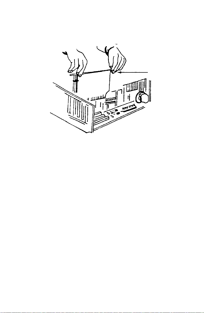
STEP 1: Insert the Modem Into the Computer
Inserting the board into the groove.
Installation Procedure
1. Turn off and unplug the computer.
2. Unplug all the peripheral devices (screen, printer,
etc.).
3. Remove the computer's cover to have easy access
to the internal bus connectors.
4. Choose an unused expansion slot and remove its
bracket (shaped like a square ruler) located on the
back panel.
5. Insert the board into the groove making sure that its
edge makes contact with the back panel of the
machine.
6. Fasten the edge to the computer's panel, replace
the cover and screws.
7. Plug in the end of the phone cord that came with
the modem into the modem's TELCO jack (The
6 Sportster Winmodem 33600 & x2/56K - User's manual
Page 11
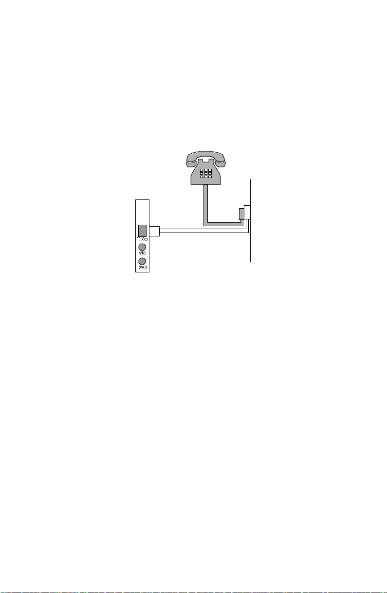
TELCO jack is accessible through an opening in the
computer's case.)
8. Plug the other end of that cord into a wall jack for
an analog line.
9. If you want to use a telephone on that line, the
setup is as follows:
Plug the telephone's cord into the
telephone wall jack as shown above.
10. Plug in the power plug and turn the computer on.
Sportster Winmodem 33600 & x2/56K - User's manual 7
Page 12

STEP 2: Run the Modem’s Installation Program
Sportster Winmodem 33600 & x2/56K comes with an installation
diskette that contains an installation program that will help your
computer finish installing the modem. This program will also copy
modem programs from the diskette onto your computer’s
hard drive.
The installation program runs a little differently for Windows 95
than it does for Windows 3.1 and 3.11. In this section, follow the
steps for the Windows operating system you have. Skip the
other set of Windows instructions.
Running the Installation Program on a Windows 3.1 or
3.11 System
After inserting the Sportster Winmodem 33600 & x2/56K by
following the steps previously described in the
the Modem Into the Computer
1. Insert the installation diskette.
2. Run the a:install program. From Program Manager,
pull down the File menu and select Run. Enter
A:INSTALL.EXE if that is the drive you are running
the installation diskette from.
3. Follow the screen commands to complete the
installation program.
section page 6 :
STEP 1: Insert
NOTE:
modem. Choose any port that’s labeled Free. Do not choose a
port labeled In use. (If you choose an In use port, the device that
has been using that port will not work.)
Write the COM port on the first page of this manual. You may
need to know the number later.
When you’ve finished the installation program, Windows will
restart.
8 Sportster Winmodem 33600 & x2/56K - User's manual
At one point you’ll be asked to select a COM port for the
Page 13

At this point, you’ll either:
• Be able to find the Sportster Winmodem 33600 &
x2/56K group in the Program Manager window: If you
can find this group, you’re ready to install the
communications software.
OR
• If the computer cannot configure the modem
automatically, you will get a Configuration dialog box.
You will have to choose an available I/O address and
an available IRQ. (NOTE: Do not check the Let Plug &
Play configure… option.)
• For the I/O address: Choose any on the list.
• For the IRQ: The COM port/IRQ combinations
shown here work with most computer set-ups:
If you choose
this COM port
14
23
3 5, 7 or 9
4 5, 7 or 9
If you have a sound card, SCSI card, or game card, it might be
using IRQ 5 or 7. Do not make 5 or 7 your first choice then,
because it might not be available.
:
If the configuration you’ve chosen works
find the
Program Manager
ready to install the communications software following the
directions page 11.
Sportster Winmodem 33600 & x2/56K
window. If you can find this group, you’re
Then try
this IRQ:
, you should be able to
group in the
Sportster Winmodem 33600 & x2/56K - User's manual 9
Page 14

If the configuration you’ve chosen does not work
I/O address and/or an IRQ that is not available:
If you chose an unavailable I/O address, you will get an error
message. Choose another I/O address in the
dialog box that appears.
If you chose an unavailable IRQ, you’ll find out later when your
communications software program tells you it cannot find the
modem. At that point choose another IRQ in the
dialog box. (You can find it by clicking on the
in the
Sportster Winmodem 33600 & x2/56K
Program Manager
window.)
, you chose an
Configuration
Configuration
Configuration
group in the
icon
Running the Installation Program on a
Windows 95 System
After inserting the Sportster Winmodem 33600 & x2/56K by
following the steps in the
Computer
section page 6 :
1. When the screen tells you to, insert the installation
disk.
2. Follow the screen commands to complete the
installation program.
STEP 1: Insert the Modem Into the
NOTE: At one point, you’ll be told which COM port the modem
has been installed on. Write the COM port on the first page of
this manual. You may need to know the number later.
When you’ve finished the installation program, a Sportster
Winmodem 33600 & x2/56K icon will appear in the Control Panel
window. You’ll then be ready to install the communications
software. See instructions below.
10 Sportster Winmodem 33600 & x2/56K - User's manual
Page 15

STEP 3: Installing the Communications Software
You’ll need communications software to get the modem working
— dialing numbers, downloading files, sending faxes, etc.
• If you’re asked to select your modem type from a
list, select a high speed Sportster or Courier Dual
Standard.
• If you cannot select a Sportster or Courier model
from the list, try:
1. Typing this “initialization string:” AT&F1
2. And then pressing the ENTER key.
• If you’re asked for a serial port (baud) rate, se t
the rate for the highest option. (115.200 bps is a
good choice for most programs.) If you experience
trouble later (unusually slow transmissions, errors in
transmissions, etc.), reduce the rate. Do not choose
28.800 bps, 14.400 bps, or 12.000 bps, however.
Sportster Winmodem 33600 & x2/56K will not work
properly at these serial port rates.
• If you have to specify the COM port being used,
refer to the number you wrote on the first page of this
manual.
If you are asked to specify a flow control setting, choose
RTS/CTS for hardware flow control (highly recommended) or
XON/XOFF (the &F2 command) for software flow control.
Disable the type of flow control you are not using.
Sportster Winmodem 33600 & x2/56K - User's manual 11
Page 16

12 Sportster Winmodem 33600 & x2/56K - User's manual
Page 17

Changing Country Setup
under Windows 95
When tra velling with the Sportste r Winmodem PC Card, you may
need to change the country setup to attain correct operation
using other telephone networks. These networks may use
different t echnical parameters, such as Ring pattern and Voltage
level.
Using Windows 95, f ollow t he procedure below for changing to
the required country setup.
1. Click
2. Select (double-click) the ‘
3. From within the ‘Properties…’ dialogue box, click the
Note: A warning reminds you that selecting another country
different from the one that actually matches your present
location may cause the Sportster Winmodem PC Card to
operate incorrectly.
Start | Settings | Control Panel
Windows 95 task bar.
Sportster Winmodem PC Card’
icon.
Change Country’
‘
Sportster Winmodem 33600 & x2/56K - User's manual 13
button.
from the main
Page 18

3. Click OK. The ‘Modem: Change Country Set up’ dialogue box
should appear.
Note: The upper-half of this window displays the current country
selected. The lower section displays a series of flags offering
alternative setup options.
4. Select the appr opriate countr y flag and Click OK. Click on
Yes to Save.
Note: The Sportster Winmodem PC Card will be reconfigured
automatically.
To revert back to the original country specification, you must
repeat the above procedure.
14 Sportster Winmodem 33600 & x2/56K - User's manual
Page 19

Using the Modem
Installation Test
Follow this procedure to check that the modem works correctly.
1. Turn the computer on.
2. Load and run the communications software.
Check the software installation manual for further
information. Do not be alarmed when a DOSbased hardware diagnostic tool does not detect
the presence of your new modem. The new
architecture of Sportster Winmodem 33600 &
x2/56K is unknown to many comtest programs and
DOS-based tools.
3. In the software, set the serial port rate to 9.600
bits per second (bps) f or a V. 22 bis modem,
19.200 bps for a V.32 bis modem, 57.600 bps for a
V.34 model, 57.600 bps (115.200 bps if available)
for a V.34+ model (in some software, this is
referred to as the 'baud rate’). The modem will
automatically detect this setting when you send a
command to it.
4. Specify the serial communications port used by the
modem: COM1, COM2 or other.
5. Set the data format to an 8-bit length with no parity
or to a 7-bit length with even or odd parity — either
one will do — and 1 stop bit.
Sportster Winmodem 33600 & x2/56K - User's manual 15
Page 20

6. Execute the function that authorizes sending AT
commands to the modem; in other words, put the
computer in terminal mode.
7. Verify that the computer and the modem can
communicate with each other by sending the
following AT command (you can type the
command either with uppercase or lowercase
letters, but you must not combine the two
different types of letters). Press the Enter key
(carriage return) , indicated in the following example
by the word Enter surrounded by brackets.
$7(QWHU!
If everything is OK, the modem will respond with the following
message:
2.
If the command is not echoed back (AT is not displayed on the
screen), it means that local echo is turned off. In order to turn it
on, send the following command to the modem :
$7((QWHU!
If, on the contrary, the screen displays double characters, it
means that local echo is turned on both at the modem and in the
software. Turn the software local echo off, if such an option is
available, or turn the modem local echo off with the following
command:
$7((QWHU!
Factory Settings
The modem has been pre-configured at the factory. In most
cases, it will work properly with these factory settings. However,
if necessary, you can modify them with the communication
commands.
In order to display the present modem settings, do the following:
1. Run the communications program.
2. Go into the program's terminal mode.
3. Type:
16 Sportster Winmodem 33600 & x2/56K - User's manual
Page 21

$7,(QWHU!
The modem will respond to this command by displaying a list of
the configuration settings.
To modify them, please refer to Appendix A.
Resetting the Modem to Factory Settings
Some transmission sessions can modify the modem's
configurations. If you are unsure of the current configuration of
the modem or if it seems to be not working correctly, you might
want to reset it to the factory settings.
To do this:
1. Run the communications program.
2. Go into the program's terminal mode.
3. Type:
$7)(QWHU!
This re-initialization includes resetting the hardware flow control,
a fixed speed on the communication port and complete result
codes.
If you want to set software flow control on (XON/XOFF), type
the following command instead:
$7)(QWHU!
On the other hand, some communications programs let you
choose the modem in a menu list. If you can't find your modem
there, you can enter these initialization strings above in the
settings screen of the application.
Sportster Winmodem 33600 & x2/56K - User's manual 17
Page 22

Remarks on Using the Modem
Remember the Following Points When Using the
Modem:
• The modem might not work with all modular
telephone sets. Specifically, you must not use the
modem with multi-line telephone sets, sets with
indicator lights or line selection buttons.
• Some voice mail message systems use a specific
tone to indicate that a voice message has been
received. The modem will not be able to dial as long as
this signal is on the line. Listen to the waiting
messages in order to get the normal dial tone back
so that the modem can dial.
• The modem has an automatic speed reduction
function. This means that it automatically reduces its
data transmission speed in order to match the speed
of the remote modem. This also means that it may
take the modem up to 30 seconds to establish
communications with a slower modem.
• A comma (,) in the dialed number causes a pause
during dialing. You can insert multiple commas in the
command line in order to obtain a longer pause.
• The modem must detect a carrier within a specific
time interval, otherwise it will display the message ‘NO
CARRIER’ or ‘NO ANSWER’. You can increase this
interval (in seconds) by going into the terminal mode of
the communications application and typing in:
$76 >YDOXH@
NOTE: This
the AT command table for further details). The range of
acceptable values is country-dependent.
18 Sportster Winmodem 33600 & x2/56K - User's manual
value
must be between 1 and 255 seconds (refer to
Page 23

Un-Installing the Modem
Un-installing the Sportster Winmodem 33600 & x2/56K requires
that you:
• Remove the modem from the expansion slot
turning off your computer.
• Remove the modem programs from the computer’s
hard drive
after
turning your computer back on. You
should do this with the “uninstall” program, which can
be found:
In the Sportster Winmodem 33600 & x2/56K
group of the Program Manager window in
Windows 3.1 and 3.11 systems
In the Sportster Winmodem 33600 & x2/56K
icon of the Control Panel window in Windows
95 systems
It does not matter which of these you do first — removing the
modem or removing the modem programs — but you must do
both to completely un-install the modem.
after
Sportster Winmodem 33600 & x2/56K - User's manual 19
Page 24

20 Sportster Winmodem 33600 & x2/56K - User's manual
Page 25

Troubleshooting
Problems and Solutions
If you encounter problems even though you have followed the
installation and use instructions of the modem, refer to the
following table that lists the most common failures and their
solutions.
Identifying the current problem
Symptom Solution
The software
indicates that the
modem is not
installed.
The modem displays
double characters on
the terminal screen.
Sportster Winmodem 33600 & x2/56K - User's manual 21
Check the software configuration.
Make sure that it is configured for the
appropriate COM port (in most cases it
should be set to COM2). Check also that
no other application is using this same
port. Check also that the modem is
properly inserted in its casing.
Both the modem and the application
local echoes are turned on.
To turn local echo off type:
$7((QWHU!
Page 26

The modem does not
respond when, in
terminal mode, you
send AT commands.
Check that the COM port to which the
modem is connected is properly
declared. Check the IRQ configuration in
the communications software or in the
Windows Control Panel. Check that
the application is in terminal mode.
If none of the preceeding solutions solve
the problem, it means that the modem is
certainly in conflict at the COM port/IRQ
level. Begin the installation procedure in
the Installation chapter. If you change
the COM/IRQ configuration, don't forget
to make these changes in the application
as well.
The modem cannot
make a call and sends
the message ‘NO DIAL
TONE’.
The modem cannot
make a call when
connected to a PBX.
Check the connection to the telephone
line. It could be that the modem cannot
detect the dial tone.
Try the ATX3DT<phone number> dial
sequence.
A pause in dialing may be needed to
allow time to connect to the outside
PSTN line. An example of dialing an
outside line is shown below, where a 9 is
used to access the outside line and a
comma causes a pause in the dialing
sequence.
$7'
The value of register S8 may be
adjusted to give the required delay, or
use a W in place of a comma. The W
causes the modem to wait for a second
dial tone before continuing and may
result in faster dialing.
22 Sportster Winmodem 33600 & x2/56K - User's manual
Page 27

There is no audible
tone when you try to
call.
The speaker is turned off; reset the
modem's settings to the factory settings.
The cables are not correctly connected.
Check all connections from the
telephone wall jack to the modem.
There is a problem with the telephone
line; check it using a standard telephone
set.
You are connected to an incompatible
telephone network. Refer to the section:
‘Utilization Notes’ in this manual.
The modem does not
respond to incoming
calls.
The modem connects
to the remote modem,
but the text received
is illegible.
Using a certain
terminal emulation
application, the
modem sends back
many transmission
errors.
Check that the application's auto-answer
mode is turned on.
Some office networks use a low voltage
call signal that the modem cannot
recognize. Try connecting the modem to
a line that is not part of this type of
network.
Incorrect software configuration. Check
that the transmission speed, the parity
and the number of stop bits defined in
the software correspond to the settings
of the remote modem. Data compression
could be used on one of the modems
and not on the other. Check the flow
control. If required, reconfigure the
modem to the factory settings.
Check the way the application initializes
the modem :
$7)(QWHU!
This re-initialization includes resetting
the hardware flow control.
If you want to set software flow control
on (XON/XOFF), type the following
command instead:
$7).(QWHU!
Sportster Winmodem 33600 & x2/56K - User's manual 23
Page 28

The modem
connects itself
correctly to the
remote modem, but
the connection is
interrupted during
communications
with the message:
NO CARRIER.
Someone probably hung up from another
extension.
The modem detected a call waiting signal
on the line. Contact the local telecommunications agency to find out how
to turn this signal off when you use the
modem.
Try calling another modem to check if
the problem is general or unique to one
specific modem.
The telephone line is of low quality; try
communicating at a lower speed.
Connection problem
with a 2400 bps
modem.
High speed data
transmission failed.
International
connections cannot
be made.
Calls to foreign
countries terminate
with a ‘NO CARRIER’
message.
Some older modem models will not
connect when the error correction protocol
is on. Turn this protocol off with the
following command:
0,66,1*&200$1'
Check if there are any time-share
applications or programs working in
parallel to the communications application.
The quality of the telephone line is too
low to withstand high-speed data transfer;
decrease the modem's transmission
speed.
Because of the length of the number
dialed and the differences in telephone
networks, it may be the case that some
digits do not get interpreted during the
dialing process. Insert commas between
parts of the dialing number in order to
create pauses.
For example, if you are calling 123456789,
insert commas and dial 1,23,456789
instead.
Increase the amount of time to wait for
a carrier signal. In terminal mode, type
and press the Enter key. The
ATS7=60
range of acceptable values is countrydependent.
24 Sportster Winmodem 33600 & x2/56K - User's manual
Page 29

Intercontinental
connections are
sometimes
interrupted.
If the telephone line's quality is low, it is
best to reduce the transmission speed in
order to insure that the connection
remains stable.
During file transfer,
the modem sends
back many
transmission errors
or a very low
transfer rate.
During transmission
of a fax, errors alter
its legibility or cut
off the connection.
You get a message
telling you that the
modem is conflicting
with another device.
The telephone line is bad, select a lower
transmission speed.
Re-initialize the modem to the factory
settings.
Change the transfer protocol.
Check the modem's and the software's
flow control.
Remove all 'Terminate and stay resident'
programs (TSRs) that could be active
during the connection.
If the problem occurs during the transmission of a fax from Windows or OS/2
check that the communications driver that
you are using is the one corresponding to
the environment that you use (Windows,
OS/2), or the one supplied specifically with
the communications software.
With a Windows 3.1 or 3.11 system:
Click on the
Configurator
icon in the
Sportster Winmodem 33600 & x2/56K
program group to get access to changing
the setting(s). Try different I/O addresses
and IRQ lines. If that does not work, you
may need to free up an I/O address or
IRQ line.
With a Windows 95 system:
1. Click on the Start button.
2. Scroll to Help.
3. Click on the Contents tab.
4. Select Troubleshooting.
5. Select If you have a hardware conflict.
6. Follow the screen commands.
Sportster Winmodem 33600 & x2/56K - User's manual 25
Page 30

Before the Modems Connect
If your modem
does not respond to
AT commands.
If your modem does
not answer the
phone or does not
“go off hook” to
answer the phone.
•
Make sure you are in terminal mode.
(Your communications software should
let you switch to terminal mode.)
•
Check that the modem is set to display
result codes and that the result codes
are displayed as words.
•
Try going into terminal mode and:
1. Typing
ATE1V1Q0
(the last character is
zero)
2. And then pressing the
•
(See
Qn
and
Vn
in the
ENTER
Commands
chapter.)
•
Check that your modem’s Data Terminal
Ready (DTR) signaling is set correctly.
(See
&Dn
in the
chapter.)
Commands
You may need to review the manual that
came with your communication software
to see what DTR operation your
software requires. If you are not using
the communication software that came
with the Sportster Winmodem 33600 &
x2/56K , you may need to change the
DTR setting.Check the manual that
came with the software.
•
Review the manual that came with your
communication software to see what
Data Terminal Ready (DTR) operations
are required. (See
Commands
chapter of this manual,
&Dn
in the
too.) If you are not using the
communication software that came with
the modem, you may need to change
the DTR setting. Check the manual that
came with the software.
•
Try going into terminal mode (your
communications software should let
you switch to terminal mode) and:
1. Typing
ATX3DT
2. And then pressing the
•
(For answering:) Make sure your
as the dial string
key
ENTER
software has “auto answer” enabled.
key
26 Sportster Winmodem 33600 & x2/56K - User's manual
Page 31

If your PC reacts as
though you are
online, but no call
has been initiated or
received.
•
Check that modem’s Carrier Detect
(CD) signaling is set correctly. (See
in the
Commands
chapter.) You
&C
n
may need to review the manual that
came with your communication
software to see what CD operation your
software requires. If you are not using
the communication software that came
with the modem, you may need to
change the CD setting. Check the
manual that came with the software.
If double characters
are displayed on
your screen
(Example: AATT).
If both modems
exchange carrier
signals but fail to
establish a data
communications
link.
•
Both your modem and your
communications software’s local echo
features are on. Turn one off by going
into terminal mode (your
communications software should let
you switch to terminal mode) and:
1. Typing
2. And then pressing the
•
Place the call again. You may have had
(the last character is zero)
ATE0
ENTER
a bad phone line or a bad connection.
The telephone company routes all
calls, even local calls, differently each
time you call.
•
Call a different modem to see if the
problem persists.
•
The remote modem might be an older
2400 bps modem that does not support
error control. Disable error control by
going into terminal mode (your
communications software should let
you switch to terminal mode) and:
1. Typing
(the last character is
AT&M0
zero)
2. And then pressing the
3. Typing
followed by the telephone
ATDT
ENTER
number
4. And then pressing the
ENTER
key
key.
key.
Sportster Winmodem 33600 & x2/56K - User's manual 27
Page 32

If both modems
exchange carrier
signals but fail to
establish a data
communications
link.
(cont.)
When the call is finished, reset the
modem by:
1. Typing ATZ
2. And then pressing the
ENTER
key.
Make sure you’ve set your software to the
same data format (word length, parity, and
number of stop bits) required by the
modem you’re trying to connect with and,
if your modem is dialing out, that your
software is set to a baud rate equal to or
higher than that of the other modem.
NOTE:
Using a data format different
from the other modem’s can alter data.
If you cannot call to find out the other
modem’s data format, trying the
following data formats in this order:
8-None-1, 7-Even-1, 7-Odd-1, and 7Mark-1.
•
Make sure your modem’s connection
rate isn’t locked. The default of
&N0
last character is zero), the variable
connection rate, lets the two modems
negotiate the best possible connection
rate. (See
&N
n
in the
Commands
chapter.)
•
Make sure the modem is in the right
mode for what you’re trying to do:
•
Data mode for a data call.
•
Fax mode for a fax call.
(the
28 Sportster Winmodem 33600 & x2/56K - User's manual
Page 33

During Data Transfers
If your screen
displays random or
garbage characters.
•
Make sure your communications port is
set to connect at the maximum possible
connect rate.
•
Set your software to the same word
length, parity, and stop bits as the
remote modem.
•
Peripherals (drivers for hardware and
software) may be interfering with the
transmission. Try disabling the
extensions before you run your
communications software.
•
The flow control settings for your
software and modem may be different.
Check to see that your software and
the modem are set for the same kind of
flow control, either hardware or
software (hardware is recommended).
Some communications programs also
require that you disable the kind of flow
control you are not using.
•
Load the template that enables
hardware flow control as well as other
optimal settings. Go into terminal mode
(your communications software should
let you switch to terminal mode) and:
Type
1.
2. And then press the
AT&F1
ENTER
key.
If the settings are the same, the
problem may be with the phone line.
Sportster Winmodem 33600 & x2/56K - User's manual 29
Page 34

If your communi-
•
cations software is
reporting many
Cyclic Redundancy
Check (CRC) errors
and low Characters
•
Per Second (CPS).
•
During Fax Transmissions
Place the call again. You may have had
a bad phone line or a bad connection.
The telephone company routes all
calls, even local calls, differently each
time you call.
Load the template that enables
hardware flow control as well as other
optimal settings. Go into terminal mode
(your communications software should
let you switch to terminal mode) and:
Type
1.
2. And then press the
AT&F1
ENTER
key.
Try the Zmodem file transfer protocol. If
that does not work, try Ymodem. (Only
use Xmodem as a last resort.)
If errors are
occurring in your
V.17 (14.4) fax
transmissions
Type this initialization string in your
software initialization string screen:
$7+,56
(last character is zero)
30 Sportster Winmodem 33600 & x2/56K - User's manual
Page 35

If You Are Still Having Problems
• Re-read this manual, especially the Remarks on
Using the Modem section.
• Contact your reseller who will be able to provide you
with the necessary assistance. This is much more
efficient and less costly than sending the modem back
to us for a problem that is possibly only a simple
matter of adjusting the settings.
• If your reseller can't help you, contact your PC
Company Customer Support. When you call, specify
your modem serial number (found on the modem and
on the outside of the box), the software being used,
and, if possible, the contents of your ATI7 screen.
Sportster Winmodem 33600 & x2/56K - User's manual 31
Page 36

32 Sportster Winmodem 33600 & x2/56K - User's manual
Page 37

Voice Functions
Overview of Voice Functions
A voice modem has the capability of being able to transform
analog sound data — such as voices — into digital data that are
compatible with computers. This digitization operation is called
sampling. Once the data is in digitized form, it can be stored on
the computer's hard disk in files and be converted and
processed by specific applications. On the other hand, this
digitized data can be re-transmitted to the voice modem which
reconstructs the original sounds from it.
If most messages transit over the telephone line, the modem
user can use, according to the available equipment :
• a telephone set
• a sound card connected to a microphone and
speaker, to record and listen to messages
• the built-in
communication
Please refer to the
how to set up your modem for voice functions.
These capabilities, coupled with the power of specific computer
applications, can be used for the PC to simulate either an
answering machine, voice mail or any other communications
application that processes voice data.
speakerphone
Installation
feature, allowing hand free
section page 5 for instructions on
Sportster Winmodem 33600 & x2/56K - User's manual 33
Page 38

Speakerphone
The full duplex SpeakerPhone feature of the modem is
accessible by connecting an external speaker to the jack on
modem backpanel and a microphone.
NOTE:
30 centimeters apart and not directly facing each other, so as to
avoid acoustical coupling between the speaker output and
microphone input.
Make sure that the microphone and speaker are at least
Impl ementing Voice Functions
Voice Applications
To use the voice functions of the modem, you must use
an application designed for this type of modem. The answering
machine, voice mail, differentiating Data – Fax – Voice calls and
recognition of remote telephone tones (DTMF) are the main
functions used by voice applications.
Application Settings
In the section corresponding to the modem settings in the voice
application, choose the exact modem type in the list of modems
displayed.
If the modem is not included in the list, you can:
1. Try a modem containing words such as ‘Generic’ or
‘voice modem’.
2. Contact the software manufacturer to ask for
advice on choosing the driver; be sure to mention
that your voice modem recognizes AT #V type
commands.
3. Contact your modem reseller.
34 Sportster Winmodem 33600 & x2/56K - User's manual
Page 39

In the following paragraphs, you will find some indications
pertaining to the settings of voice applications in order to use the
modem.
Input/Output Source Selection
Set the recording or playback sources as the devices from which
you are going to record the local message and listen to the
received messages. (External powered speakers, microphone,
headset or sound card)
Recording and Playback Quality
The greater the sampling rate, the better the quality of the
message is. This also means also that the message file size on
the disk will be greater. For example, 10 seconds recorded on 2
bits equals about 18 kbytes, whereas a message with twice the
quality (4 bits) will require, for 10 seconds, about 36 kbytes.
Level and Length of Silence
Aside from the various adjustments to recording or playback
levels, there are usually two of them that relate to the silence.
These settings are used, one to set the 'minimum noise' level on
the line that the modem can consider as silent, the other the
maximum length of silence before going on hook.
Sportster Winmodem 33600 & x2/56K - User's manual 35
Page 40

36 Sportster Winmodem 33600 & x2/56K - User's manual
Page 41

A ppendix A – Technical
Reference
Main AT commands
1. Type the commands entirely in upper case or lower
case but do not type commands using a
combination of the two cases.
2. All commands, with the exception of A/ and +++,
are preceeded by the AT prefix and are executed
after pressing the Enter/ Carriage Return key
(<Enter>).
3. The maximum length of a command is 40
characters. The modem does not count the AT
prefix character, the Enter key or spaces. On the
other hand, it does count punctuation marks such
as dashes and parentheses.
4. Any missing numeric parameter is considered to be
equal to zero, for instance the disconnect
command: ATH <Enter>, is equivalent to ATH0
<Enter>.
Sportster Winmodem 33600 & x2/56K - User's manual 37
Page 42

Basic Command Set
AT
$
A/
+++
&$
Any key
A
BnU.S./IT U- T answer sequence.
DnDials the specified phone number.
DL Dials the last-dialed number.
DS
D$ Displays a list of Dial commands.
EnSets local echo.
Required command prefix, except with A/ and +++.
Use alone to test f or
OK
result code.
Display s a ba s ic c o mmand list; online help.
Re-executes the last issued command.
Used mainly to redial.
This does not require the AT prefix or a Carriage
Return.
Escapes to online-command mode.
Displays a list of ampersand (&) commands .
Aborts of f - hook dial/answer operat ion and hangs up.
Manual Answer : goes off hook in answer mode.
Pressing any key aborts the operation.
B0 ITU-T answer sequence.
B1 U.S. answe r tone.
Includes any of the following.
P Pulse (rotary) dial.
T Tone dial.
, (Comma) Two-second pause; linked to S-8 r egist er
; (Semicolon) Return to
Command
mode after dialing.
“ Dials the letters that follow ( in an alphabet ical phone
number).
/ Delays for 125 msec. bef or e pr oceeding with dial
string.
W Wait for second dial tone (X3 or higher); linked to S6
register.
@ Dials, waits for quiet answer, and continues (X3 or
higher ) .
R Originates call using answer (reverse) frequencies.
n
Dials the phone number string stored in NVRAM
position
n (n
= 03).
Phone numbers are stored w it h the &Zn=s comma nd .
at
38 Sportster Winmodem 33600 & x2/56K - User's manual
Page 43

E0 Echo OFF.
E1 Modem displays keyboard commands.
Sportster Winmodem 33600 & x2/56K - User's manual 39
Page 44

FnSets online local echo of transmitted data O N/ O FF.
F0 Local echo ON. Modem sends a copy of data it sends
to the remote system to your screen.
F1 Local echo OFF.
Receiving system may send a remote echo of data it
receives.
HnControls ON/ OFF hook.
H0 Hangs up (goes on hook)
H1 Goes off hook.
InDisplays the following information.
I0 Four-digit product code.
I1 Results of ROM checksum.
I2 Results of RAM checksum.
I3 Product type.
I4 Current modem settings.
I5 Nonvolatile memory (NVRAM) settings.
I6 Link diagnostics.
I 7 Product confi gur at i on.
I8 Returns the blacklisted phone numbers.
LnControls speaker volume (internals only).
L0 Low.
L1 Low.
L2 Medium.
L3 High.
MnOperates speaker .
M0 Speaker always O FF.
M1 Speaker ON until CONNECT.
M2 Speaker always O N.
M3 Speaker ON after dial, until CONNECT.
OnReturns online.
O0 Returns online.
O1 Returns online and r etrains.
P Sets pulse dial (for phone lines that don’t support
touchtone dialing).
Qn Displays/suppresses r esult codes.
Q0 Displays result codes.
Q1 Q uiet mode; no result codes.
Q2 Displays result codes only in
S
r.b=n
Sets bit
.b
of register r to n (0/OFF or 1/ON).
Ori ginate
mode
40 Sportster Winmodem 33600 & x2/56K - User's manual
Page 45

Sr=
n
Sets register r to n.
(See list of S-r egist er set tings on the next sect ion).
Sr? Displays contents of S-r egister r.
S$ Displays a list of the S-Registers.
(See list of S-r egist er set tings on the next sect ion).
T Sets tone dial.
VnDisplays verbal/numeric result codes.
V0 Numeric codes.
V1 Ver bal codes.
XnSets result code displayed. Default is X4.
Sportster Winmodem 33600 & x2/56K - User's manual 41
Page 46

Xn Setting
Result Codes
0/OK
1/CONNECT
2/RING
3/NO CARRIER
4/ERROR
5/CONNECT 1200
6/NO DIAL TONE
7/BUSY
8/NO ANSWER*
10/CONNECT 2400
13/CONNECT 9600
18/CONNECT 4800
20/CONNECT 7200
21/CONNECT 12000
25/CONNECT 14400
43/CONNECT 16800
85/CONNECT 19200
91/CONNECT 21600
99/CONNECT 24000
103/CONNECT 26400
107/CONNECT 28800
151/CONNECT 31200
155/CONNECT 33600
Functions
Adaptative Dialing
Wait for 2nd dial tone (W)
Wait for answer (@)
Fast Dial
X0 X1 X2 X3 X4 X5
••••••
••••••
••••••
••••••
••••••
•••••
••
•••
•••
•••••
•••••
•••••
•••••
•••••
•••••
•••••
•••••
•••••
•••••
•••••
•••••
•••••
••••
•••
••
••
••
*Requires @ in dial string; replaces NO CARRIER
42 Sportster Winmodem 33600 & x2/56K - User's manual
Page 47

YnSelects power-on/r eset default configuration.
Y0 Default is profile 0 setting in NVRAM.
Y1 Default is profile 1 setting in NVRAM.
Z Resets modem based on factor y set t ings.
Z0 Reset s modem to NVRAM profile selected by Y
command.
Z1 Reset s modem to NVRAM profile 0.
Z2 Reset s modem to NVRAM profile 1.
Z3 Reset s modem to fac t or y default profile 0 (&F0).
Z4 Reset s modem to fac t or y default profile 1 (&F1).
Z5 Reset s modem to fac t or y default profile 2 (&F2).
Advanced Command Set
&A
n
Enables/disables ARQ codes.
&A0 ARQ result codes disabled.
&A1 ARQ result codes enabled.
&A2 V.32 modulation indicator added.
&A3 Protocol indicators addedLAPM/MNP/NONE
(err or control) and V42BIS/MNP5 (data
compression) .
&B
n
Sets modem’s serial port rate.
&B0 Variable, follows connection rate.
&B1 Fixed serial port rate.
&B2 Fixed in ARQ mode, variable in non-ARQ
mode.
&C
n
Controls Carrier Detect (CD) signa l.
&C0 CD override.
&C1 Nor mal CD operations.
&D
n
Controls Data T er minal Ready (DTR) oper at ions.
&D0 DTR override.
&F
&D1 DTR toggle causes online
&D2 Nor mal DTR operations.
&D3 Resets on receipt of DTR.
n
Loads a read-only (non- pr ogr ammable) factor y
configuration.
&F0 Generic template.
&F1 Hardwar e f low control t emplate.
&F2 Software flow control template.
Command
mode.
Sportster Winmodem 33600 & x2/56K - User's manual 43
Page 48

&G
&H
&I
&K
&M
&N
n
Sets Guar d Tone.
&G0 No guard tone, U.S. and Canada.
&G1 550 Hz guard tone, some European
countries, r equires B0 sett ing.
&G2 1800 Hz guard tone, U.K., r equires B0
setting.
n
Sets Transmit Data(TD) flow control.
&H0 Flow control disabled.
&H1 Hardware f low control, Clear t o Send (CTS).
&H2 Soft ware flow contro l, XO N/XOFF.
&H3 Hardware and softw ar e c ontrol.
n
Sets Receive Data (RD) soft ware f low control
(see also &Rn).
&I0 Softw ar e f low contr ol disabled.
&I1 XON/XOFF signals to your modem and
remote system.
&I2 XON/XOFF signals to your modem only.
n
Enables/disables data compression.
&K0 Data compression disabled.
&K1 Auto enable/disable.
&K2 Data compression enabled.
&K3 MNP5 compression disabled.
n
Sets Error Contr ol ( ARQ) 1200 bps and higher.
&M0 Nor mal mode, err or control disabled.
&M1 Reserved.
&M2 Reserved.
&M3 Reserved.
&M4 Normal/ARQ.
&M5 ARQ mode.
n
Sets forced connect speed. I f c onnect ion cannot be
established at this speed, the modem will hang up.
&N0 Variable rate.
&N1 300 bps.
&N2 1200 bps.
&N3 2400 bps.
&N4 4800 bps.
&N5 7200 bps.
&N6 9600 bps.
&N7 12.000 bps.
&N8 14.400 bps.
44 Sportster Winmodem 33600 & x2/56K - User's manual
Page 49

&P
&R
&S
&T
&W
&Y
&N9 16.800 bps.
&N10 19.200 bps.
&N11 21.600 bps.
&N12 24.000 bps.
&N13 26.400 bps.
&N14 28.800 bps.
&N15 31.200 bps.
&N16 33.600 bps.
n
Sets pulse (rot ary) dial make/break ra t io.
&P0 U.S./Canada ratio, 39%/61%.
&P1 U. K. ratio, 33%/ 67% .
n
Sets Receive Data (RD) hardware f low control,
Request to Send (RTS) (see also &I
&R1 Modem ignores RTS.
&R2 Received Data to computer only on RTS.
n
Controls Data Set Ready (DSR) operations.
&S0 DSR override; alw ays O N.
&S1 Modem controls DSR.
n
Begins test modes.
&T0 Ends testing.
&T1 Analog Loopback.
&T2 Reser ved.
&T3 Local Digital Loopback.
&T4 Enables Remote Digital Loopback.
&T5 Pr ohibits Remote Digital Loopback.
&T6 I nitiates Remote Digital Loopback.
&T7 Remote Digital with self test and error
detector .
&T8 Analog Loopback with self test and error
detector .
n
Writes curr ent configuration to NVRAM templates.
&W0 Modifies the NVRAM 0 template (Y 0) .
&W1 Modifies the NVRAM 1 template (Y 1) .
n
Sets break handling.
&Y0 Destructive, but doesn’t send break.
&Y1 Destructive, expedited.
&Y2 Nondestructive, expedited.
&Y3 Nondestructive, unexpedited.
n).
Sportster Winmodem 33600 & x2/56K - User's manual 45
Page 50

&Zn=sWrites phone number str ing s to NVRAM at
position
&Zn=L W r ites last execut ed dial str ing to NVRAM at
position n (n = 03).
&Zn? Displays the phone number stored at posit ion
n (n
&ZL? Displays the last executed dial string.
n (n =
= 03).
03).
S-Registers
• Default values are appropriate for most users.
The settings are modified with the ATSr=n command,
where r is the number of the S register and n is a
decimal value between 0 and 255 (unless otherwise
stated).
• Use ATSr? to examine the configuration of a
register. For example:
$76"(QWHU
Reg Default Function
S0 0 Sets t he number of rings on which to answer
in Auto Answer M ode. When set to 0, Auto
Answer is disabled.
S1 0 Count s and stores t he number of rings from
an incoming call. (S0 must be great er t han
0).
S2 43 Stores t he ASCII decimal code for the es-
cape code character. Default character is +.
A value of 128 – 255 disables the escape
code. The range of acceptable values is
country- dependent.
S3 13 Stores t he ASCII code for t he Carriage
Return char ac t er . Valid range is 0–127.
S4 10 Stores t he ASCII decimal code for the Line
Feed character. Valid range is 0–127.
S5 8 Stores t he ASCII decimal code for the Back-
space character. A value of 128255 disables
the Backspace key’s delete function.
46 Sportster Winmodem 33600 & x2/56K - User's manual
Page 51

S6 ! Sets the number of seconds the modem
waits bef or e dialing. If Xn is set to X2 or X4,
the modem ignores this register and dials as
soon as it detects a dial tone (fast dials). The
range of acceptable values is countrydependent.
S7 60 Sets the number of seconds the modem
waits for a carr ier. M ay be set f or much
longer duration if, for example, the modem is
orig inat ing an inter nat io nal co nnect ion.
S8 2 Sets the duration, in seconds, for the pause
(, ) opt io n in the Dial command.
S9 6 Sets the required duration, in tenths of a
second, of the remote modem’s carrier signal.
S10 7 Sets the duration, in tenths of a second, that
the modem waits af ter loss of carr ier bef or e
hanging up. This guard time allows the
modem to distinguish between a line hit, or
other disturbances that momentarily break
the connection, fr om a tr ue disconnect (hang
up) by the remote modem.
While we d on’t recommend connect ing t he
modem to a line with call waiting, if you have
it, you may wish to adjust this setting upward
to prevent the modem from misinterpr et ing
the second call signal as a disconnect by the
remote modem. A better alt er native is to ask
your phone company how to t emporar ily
disable call waiting (usually *70W). For
example: ATDT *70W
phonenumber
.
NOTE: If you set S10 = 255, the modem will not hang up when
carrier is lost. Dropping DTR hangs up the modem. This
possibility is country-dependent.
S11 ! Sets the duration and spac ing, in milli-
seconds, for t one dialing. The range of
acceptable values is country-dependent.
Sportster Winmodem 33600 & x2/56K - User's manual 47
Page 52

S12 50 Sets the duration, in fiftieths of a second, of
the guard time for t he escape code
sequence (+++).
48 Sportster Winmodem 33600 & x2/56K - User's manual
Page 53

Reg Default Function
S13 0 Bit-mapped register. Select the bit(s) you
want on and set S13 to the total of the values in the Value column. For example,
ATS13 = 17 enables bit 0 (value is 1) and bit
4 (value is 16).
Bit Value Result
0 1 Reset when DTR drops.
1 2 Reset non-MNP transmit buffer
from 1.5K t o 128 byt es.♦♦
2 4 Set backspace key t o delet e.
3 8 On DTR signal, auto dial the
number stored in NVRAM at
position 0.
4 16 At power on/reset, Auto Dial the
number stored in NVRAM at
position 0.
5 32 Reserved.
6 64 Reserved.
7 128 Disconnect on escape code.
♦♦The 128-byte option lets remote users with slower modems
keep data you’re sending from scrolling off their screens.
When remote users send your computer an XOFF (Ctrl-S) and
you stop transmitting, the data in transit from your modem’s
buffer doesn’t exceed the size of their screen.
This is also very helpful in situations when a remote modem/
printer application is losing characters.
S14 0 Bit-mapped register. Allowable non-default
value is 1.
Bit Value Result
0 1 The modem hangs up on receipt
of +++, returns to command
mode, and sends the NO
CARRIER result code.
1–7 Reserved.
Sportster Winmodem 33600 & x2/56K - User's manual 49
Page 54

Reg Default Function
S15 0 Bit-mapped register. To set the register s ee
the instructions for S13.
Bit Value Result
0 (zero)1 Disable ARQ/MNP for V.22.
1 2 Disable ARQ/ M NP for .22bis.
2 4 Disable ARQ/MNP for
V.32/V.32bis/V.32terbo.
3 8 Disable MNP handshake.
4 16 Dis a ble MNP level 4.
5 32 Dis a ble MNP level 3.
6 64 MNP incompatibility .
7 136 Disable V.42 detection phase.
S16 0 Bit-mapped test r egist er . Allowable value is
2.
Bit Value Result
0 Reserved.
1 2 Touch to ne di ali ng t est.
2–7 Reserved.
S17 0 Reserved.
S18 0 Test timer for &Tn loopback testing. Sets t he
time in seconds of testing before t he modem
automatically times out and terminates the
test. When set to 0, the timer is disabled.
S19 0 Sets the duration, in minutes, for the Inac-
tivity Timer. The timer activates when there is
no data activity on the phone line; at timeout
the modem hangs up. S19 = 0 disables the
timer.
S20 0 Reserved.
S21 10 Sets the length, in 10-millise c o nd units, o f
breaks sent fr om the modem to the computer; applies to ARQ mode only.
S22 17 Stores t he ASCII decimal code for the XON
character. Valid range is 0–127.
50 Sportster Winmodem 33600 & x2/56K - User's manual
Page 55

S23 19 Stores t he ASCII decimal code for t he XOFF
character. Valid range is 0–127.
S24 0 Reserved.
Reg Default Function
S25 5 Set s the durat ion, in hundr edths of a second,
that DTR mus t be dr opped so that the
modem doesn’t interpr et a random glitch as a
DTR loss . (M os t users will want to use the
default; this register is useful for setting
compatibility with older systems running
under older operating software.).
S26 0 Reserved.
S27 1 Bit-mapped register. To set the register s ee
the instructions for S13.
Bit Value Result
0 1 Enables ITU-T V.21 modulation
at 300 bps for overseas calls; in
V.21 mode, the modem
answers both overseas and domestic
(U.S. and Canada) calls, but
only originat es V.21 c alls.
1 2 Enables unencoded (non-trellis
coded) modulation in V.32
mode; r ar ely used part of I TU-T
Recommendat ion V.32.
2 4 Disables V.32 modulation.
3 8 Disables 2100 Hz answer tone
to allow two V. 42 modems to
connect more quickly.
4 16 See next page.
5 32 See next page.
6 64 Reserved.
7 128 This sett ing disables the codes
and displays the 9600 code
instead. The actual rate of the
call can be viewed on the ATI6
scr een. Us ed fo r unus ual
Sportster Winmodem 33600 & x2/56K - User's manual 51
Page 56

sof twa r e incompa tibilitie s .
Some sof t ware may not accept 7200,
12000 and 14400 bps result
codes.
52 Sportster Winmodem 33600 & x2/56K - User's manual
Page 57

Bit 4 Bit 5 Res u lt
0 0 Complet e handshaking
sequence: V.42 Detect ion,
LAPM error control, MNP.
16 0 Disable MNP.
0 32 Disable V.42 Detect ion and
LAPM.
16 32 Combined value of 48 negotiates LAPM without Detection phase. Choose this value if the
remote modem uses LAPM but
does not support the Detection
phase.
Reg Default Function
S28 (Sets the V.32 handshaking time [allowable range of
0–25.4 seconds].)
0 (zero) Eliminates the V.32 answer t ones for a f as t er
connection.
8 Default time (all times are in tenths of
seconds).
255 Disables all connections except V.32 at 9600
bps.
S29 20 Sets the duration, in tenths of a second, of
the V.21 answer mode fallback timer.
S30 0 Reserved.
S31 128 Reserved.
S32 2 Bit mapped register set up for t he 28.8 speed
modems only. To set the register , s ee t he
instructions for S13.
Bit Value Result
0 (zero)1 V.8 Call Indicate enabled.
1 2 Enables V.8 mode.
24Reserved
3 8 Disable V.34 modulation.
4 16 Disable 33.6 kbps support.
5 32 Reserved
6 64 Reserved
Sportster Winmodem 33600 & x2/56K - User's manual 53
Page 58

7 128 Reserved
Reg Default Function
S33 0 Bit mapped register set up for t he 28.8 speed
modems only. To set the register , s ee t he
instructions for S13.
Bit Value Result
0 (zero)1 Disable 2400 symbol rate.
1 2 Disable 2743 symbol rate.
2 4 Disable 2800 symbol rate.
3 8 Disable 3000 symbol rate.
4 16 Disable 3200 symbol rate.
5 32 Disable 3429 symbol rate.
6 64 Reserved.
7 128 Disable shaping.
S34 0 (zero) Bit mapped register setup. To set registers ,
see instructions for S13.
Bit Value Result
0 (zer o )1 Disable 8S- 2 D trellis e ncod ing
1 2 Disa ble 1 6 S-4D tr e llis e ncod ing
2 4 Disa ble 3 2 S-2D tr e llis e ncod ing.
3 8 Disa ble 6 4 S-4D tr e llis e ncod ing.
4 16 Disable non-linear c oding.
5 32 Disable TX level deviation.
6 64 Disable Pre-emphasis.
7 128 Disable Pre-coding.
S35S37 Reserved.
S38 0 Sets an optional delay, in seconds, befor e a
forced hang-up and clearing of the Transmit
buffer when DTR drops during an ARQ c all.
This allows time for a r emote modem to
acknowledge receipt of all tr ansmitted data
before it is disconnected.
Default 0: the modem immediately hangs up
when DTR drops.
54 Sportster Winmodem 33600 & x2/56K - User's manual
Page 59

This opt io n only applie s to connect ions
terminated by dropping DTR. If t he modem
receives the ATH command, it ignores S38
and immediately hangs up.
Sportster Winmodem 33600 & x2/56K - User's manual 55
Page 60

56 Sportster Winmodem 33600 & x2/56K - User's manual
Page 61

A ppendix B – Technical
Specifications
Sportster Winmodem 33600 &
x2/56K
Specifications
Compatibility Data
Fax
Speeds Data
Fax
Error correction
Data compression
Operation
Format (DTE-DCE)
Command set
Flow control
Telephone interface
Voice coding
Tone detection
Call differentiation
ITU-T V.42, MNP 2-4
ITU-T V.42
Full/Half duplex on 2 wire telephone line
Serial, binary, asynchronous
Compatible with the AT command set; Fax
mode: EIA 578 Class 1, EIA 592 Class 2.0
XON/XOFF, RTS/CTS
RJ11
IMA ADPCM
DTMF
Toggle between voice, fax and data
according to the country
: ITU-T V.34, V.FC, ITU-T V.32
V.23, V.22
212A, 103.
: Send and receive Group III Fax,
Class 1, Class 2.0; ITU-T V.17, V.29,
V.27
: 33.6K, 31.2K (V.34+), 28.8K, 26.4K,
24K, 21.6K, 19.2K, 16.8K, 14.4K, 12K,
9600, 7200, 4800, 2400, 1200,
1200/75, 75/1200, 300 bps
: 14.4K, 12K, 9600, 7200, 4800, 2400
bis
ter
bis
, MNP level 5
, V.22, V.21 and Bell
bis
,
Sportster Winmodem 33600 & x2/56K - User's manual 57
Page 62

Silence detect
Dialing
Call status
Configuration storage
Transmission level
Reception sensitivity
Operating temperature
Storage temperature
Transportation
temperature
Operating humidity
Storage humidity
Operating altitude
Adjustable level and duration
Pulse (pulses 0-9), tone
(DTMF 0-9, #, *)
Dial tone, busy tone, voice detect
Two modem configurations and four
telephone numbers
Country specific
Country specific
From 0 to 50 °C
From -40 to +70 °C
From -40 to +70 °C
From 20 to 80% without condensation
From 5 to 90% without condensation
3000 meters
Electrical power
Before making connections, check the safety levels on
the various interfaces:
• Telephone line connector = TNV
These indications are classified as per security standard EN 60950/A2 10/93.
• SELV: Very Low Safety Voltage
• TNV: Telecommunications Network Voltage,
voltages in compliance with standard EN 41003 08/93
criteria.
58 Sportster Winmodem 33600 & x2/56K - User's manual
Page 63

CE Mark
Electromagnetic Compatibility
This device complies with the following standards in accordance
with the European Directives 91/263/CEE.
• Immunity EN 50082-1 06/92
• Emission EN 55022 class B 08/87
Safety
This device complies with the following standard in accordance
with the European Directives 91/263/CEE: EN 60950/A2 10/93
Sportster Winmodem 33600 & x2/56K - User's manual 59
Page 64

60 Sportster Winmodem 33600 & x2/56K - User's manual
Page 65

Glossary
Analog signals
Variable and continuous waves, such as voice tones carried by
telephone lines. Compare with digital signals.
ARQ
General term qualifying error correction protocols that detect
errors and automatically re-transmit the incorrect data blocks.
See MNP and V.42.
ASCII
Acronym for American Standard Code for Information
Interchange. 7 bit binary code (0 and 1) used to represent
letters, numbers and special characters such as $,! and /.
Asynchronous transmission
Data transmission during which the time between transmission of
characters can vary. Since the time delays between characters
are not uniform, the receiving modem must be signaled when the
start and end of a characters data bits occur. Stop and start bits
are therefore added to each character transmitted.
Baud rate
Number of state transitions per second on a communications
channel. Even though it is incorrect from a strictly technical point
of view, the baud rate is often used to indicate the transmission
rate.
Sportster Winmodem 33600 & x2/56K - User's manual 61
Page 66

Bit
A 0 or a 1 reflecting the use of a binary numbering system (a
system that consists of 2 values). This system is used because
the computer only recognizes two states, off or on.
(Start/Stop bits) Signaling bits attached to a character before it
is transmitted; used for asynchronous transmissions.
Bits
(Start/Stop bits) Signaling bits attached to a character before it
is transmitted; used for asynchronous transmissions.
Bps
The rate in bits per second. Thousands of bits per second are
expressed as kilobits.
Buffer
An area of memory used as temporary storage during
input/output operations. The modem has, for example,
a command buffer.
Carrier
Continuous frequency that can be modulated or act as a support
to another data carrier signal. Carrier waves are generated and
maintained by modems via the telephone companies'
transmission lines.
Cps
Data transfer rate (Characters per second). It is generally
estimated from the binary rate and the length of characters. For
example, at 2400 bits/s, 8-bit characters with a start and stop
bit (for a total of 10 bits per character) are transmitted at an
approximate rate of 240 characters per second (cps). Some
protocols, such as the error correction protocols in the modem
use advanced techniques requiring longer transmission frames
and data compression to increase the number of characters per
second.
62 Sportster Winmodem 33600 & x2/56K - User's manual
Page 67

Data mode
Mode in which the fax/modem can send and receive data files.
A standard modem without facsimile capabilities is always in
data mode.
DCE
(Data Carrier Equipment) Termination equipment of the data
circuit. In this manual, this term applies to modems that establish
and control the data link on the telephone network.
Digital signals
Discreet and uniform signals. In this manual, the term refers to
bits 0 and 1.
DTE
(Data Terminal Equipment) Data processing terminal equipment.
Generally, a computer or terminal generates data or is the final
destination of data.
Duplex
Defines a communications channel capable of transmitting
signals in both directions (half duplex or full duplex).
Full duplex: Simultaneous flow of signals in two directions. In
micro-computer communications, full duplex can refer to
suppressing the local echo of transmitted characters..
Half Duplex: Signal flow in two directions, but only in one at a
given time. In micro-computer communications, half duplex can
refer to enabling of the local echo that causes the modem or the
software to send a copy of transmitted data to the screen of the
transmitting computer.
Error correction
Various techniques that check the reliability of the characters or
data blocks. The V.42 and MNP2-2, 10 error correction
protocols use error detection (using a CRC type control code)
and re-transmit erroneous frames (ARQ).
Sportster Winmodem 33600 & x2/56K - User's manual 63
Page 68

Fallback
(Rate adjustment). A function that lets rapid modems with error
correction control the line quality and fall back to a lower speed
if it becomes degraded. Modems go back to a higher speed if
the line quality improves.
Fax mode
Mode in which the fax/modem can transmit and receive
facsimiles.
Flow control
A method that compensates for differences in the data flow
coming in to and going out from a modem or other device. See
RTS/CTS and XON/XOFF
IRQ
Interrupt Request. In a computer, IRQs are used to temporarily
interrupt current processing when an event requires immediate
attention, such as for example, the arrival of data at the serial
port.
LAPM
Link Access Procedure for Modems. Error correction protocol
incorporated in the ITU-T V.42 recommendation. Just like the
MNP protocols, LAPM uses cyclical redundancy check (CRC)
and automatic re-transmission of data (ARQ) to guarantee data
reliability.
Local Echo
A function of the modem used to display keyboard command
and transmitted data on the screen. This function is provided
with most communications software.
MNP
Microcom Networking Protocol. Error correction protocol
developed by Microcom, Inc. and now in the public domain. MNP
protocol guarantees error-free transmissions using error
detection (CRC) and re-transmission of incorrect data frames.
64 Sportster Winmodem 33600 & x2/56K - User's manual
Page 69

The modem uses MNP 2-4 and MNP 5 error correction and data
compression techniques that are incorporated in
recommendation ITU-T V.42.
NVRAM
Non Volatile Random Access Memory which can be
programmed by the user with data that are stored when the
modem is powered down. The modem includes this kind of
memory to store a default configuration defined by the user and
loaded into random access memory (RAM) upon power up.
Parity
Error detection method that checks the correctness of
transmitted characters. Verification of characters has
been replaced by more reliable and efficient block
control methods, including Xmodem types of protocols and the
ARQ protocol implemented in the modem. Two communicating
computers must use the same kind of parity.
Protocol
Set of rules and procedures describing communications between
different devices. Protocols vary, but communications equipment
must use the same protocol in order to exchange data. Data
formats, the ready to receive or transmit states, error detection
and correction are some of the operations that can be defined in
protocols.
Remote Echo
A copy of the data received by the remote system is sent back
to the transmitting system and displayed on the screen. Remote
echo is a function of the remote system and is often used in full
duplex transmissions.
RTS/CTS
Hardware check used to tell an intelligent device to stop or
resume data transmission.
Sportster Winmodem 33600 & x2/56K - User's manual 65
Page 70

Serial transmission
Sequential data transfer, one bit at a time, using only one
electrical circuit.
Synchronous transmission
Data transmission during which both communicating devices are
synchronized by a common clock. Using this mode eliminates the
need to systematically add a stop bit and a start bit to each
transmitted character.
Terminal mode
Required simulation mode for computers to transmit data. In
terminal mode, the computer acts as though it were a dumb
terminal rather than a data processing unit. Keystrokes go
directly to the modem whether they are modem commands or
data to be transmitted via the telephone lines. Received data are
displayed directly on the screen.
Terminal
A unit whose keyboard and screen are used to send and receive
data via a communications link. A terminal differs from a microcomputer in that it has very little or no internal processing
capabilities.
Transmission rate
Number of bits transmitted per second (bit/s). Communications
channels using modems on telephone lines are set to binary
rates, generally 2400, 9600, 14400 or 28800.
Xmodem
The first of a family of error correction software protocols used
to transfer files between modems. These protocols are in the
public domain and are available on many servers. Ymodem and
Zmodem are later protocols.
66 Sportster Winmodem 33600 & x2/56K - User's manual
Page 71

XON/XOFF
Standard ASCII control characters used to tell an intelligent
device to stop or resume data transmission. In most systems,
typing <Ctrl>-S sends the XOFF character (which tells the
remote device to stop transmitting). Some equipment, including
your modem, interpret
<Ctrl>-Q as XON (which tells the remote device to resume
transmission), others interpret touching any key after <Ctrl>-S
as an XON.
Sportster Winmodem 33600 & x2/56K - User's manual 67
Page 72

68 Sportster Winmodem 33600 & x2/56K - User's manual
Page 73

Limited Warranty
U.S. Robotics warrants to the original end-user purchaser that
this product will be free from defects in materials and
workmanship for a period of five years from the date of
purchase. During the limited w arranty period, and upon proof of
purchase, the product will be repaired or replaced (with the
same or a similar model, which may be a ref urbished model) at
U.S. Robotics’ option, without charge for either parts or labor.
This limited warranty shall not apply if the product is modified,
tampered with, misused, or subjected to abnormal working
conditions (including, but not limited to, lightning and water
damage).
THIS LIMITED WARRANTY DOES NOT GUARANTEE YOU
UNI NTERRUPTED SERVICE. REPAI R OR REPLACEMENT AS
PROVIDED UNDER THIS LIMITED WARRANTY IS THE
EXCLUSIVE REMEDY OF THE PURCHASER. THIS LIMI TED
WARRANTY IS IN LIEU OF ALL OTHER WARRANTIES,
EXPRESS OR IMPL IED, I NCLUDING, BUT NOT LIM ITED TO ,
ANY IMPLIED WARRANTY OF MERCHANTABILITY OR
FITNESS FOR A PARTICULAR USE OR PURPOSE. U.S.
ROBOTICS SHALL IN NO EVENT BE LIABLE FOR ANY
SPECIAL, INDIRECT, INCIDENTAL, PUNITIVE OR
CONSEQUENTIAL DAMAGES OF ANY KIND OR
CHARACTER, INCLUDING, WITHOUT LIMITATION, LOSS OF
REVENUE OR PROFI T S, F AILURE TO REALIZE SAVINGS OR
OTHER BENEFITS, LOSS OF DATA OR USE, DAMAGE TO
EQUIPMENT, AND CLAIMS AGAINST THE PURCHASER BY
ANY THIRD PERSON, EVEN IF U.S. ROBOTICS HAS BEEN
Sportster Winmodem 33600 & x2/56K - User's manual 69
Page 74

ADVISED OF THE POSSIBILITY OF SUCH DAMAGES.
This limited warranty gives you specific legal rights. You may
have others, which vary from nation to nation. Some nations do
not allow limitations on duration of an implied warranty, or the
exclusion or limitation of incidental or c onsequential damages, s o
the above exclusion or limitation may not apply to you.
70 Sportster Winmodem 33600 & x2/56K - User's manual
Page 75

jj
Page 76

1.024.1388-00
 Loading...