

Page 1
1 / 69
User Manual
File Version: V1.0.4
Page 2

2 / 69
Contents
1. Quick Start.......................................................................................................................................................................4
1.1. Hardware Testing Environment........................................................................................................................4
1.2. Network Test Environment................................................................................................................................4
1.3. Default Parameter ............................................................................................................................................ 5
1.4. Data Transmission Test..................................................................................................................................... 5
2. Overview..........................................................................................................................................................................7
2.1. Brief Introduction.................................................................................................................................................7
2.2. Features............................................................................................................................................................... 7
2.3. Basic Parameter................................................................................................................................................. 8
2.4. Dimension............................................................................................................................................................8
2.5. Indicators and Dial switch................................................................................................................................. 9
2.6. DB9 Pin Definition............................................................................................................................................ 11
3. Product Function..........................................................................................................................................................12
3.1. Socket A Communication................................................................................................................................12
3.1.1. TCP Client Model..................................................................................................................................12
4.1.1 TCP Client Mode....................................................................................................................................12
3.1.2. TCP Server Mode................................................................................................................................. 15
3.1.3. UDP Client Mode.................................................................................................................................. 16
3.1.4. UDP Server Mode.................................................................................................................................18
3.1.5. TCP and UDP Comparison................................................................................................................. 19
3.1.6. HTTPD Client.........................................................................................................................................19
3.2. Socket B Communication................................................................................................................................21
3.3. USR-VCOM Application.................................................................................................................................. 23
3.4. Modbus Gateway..............................................................................................................................................24
3.4.1. Transmit modbus protocol in transparent mode..............................................................................24
3.4.2. Modbus RTU to Modbus TCP.............................................................................................................24
3.4.3. Modbus Active Query Function...........................................................................................................26
3.4.4. Modbus Polling Function..................................................................................................................... 29
3.5. Value-added Functions....................................................................................................................................32
3.5.1. DHCP......................................................................................................................................................32
3.5.2. DNS.........................................................................................................................................................32
3.5.3. Self-Defined Heartbeat Function........................................................................................................32
3.5.4. Self-Defined Registration Package Function................................................................................... 34
3.5.5. Web to serial..........................................................................................................................................36
3.5.6. Customized Webpage..........................................................................................................................39
3.5.7. Network Printing Function................................................................................................................... 39
3.5.8. Serial Port Packaging Mechanism.....................................................................................................41
3.5.9. Flow Calculation....................................................................................................................................42
3.5.10. Synchronous baud rate (RFC2217)................................................................................................ 42
3.5.11. KeepAlive............................................................................................................................................. 44
3.5.12. Device ID..............................................................................................................................................44
Page 3

3 / 69
3.5.13. Webpage Port......................................................................................................................................44
3.5.14. Revise MAC.........................................................................................................................................44
3.5.15. Firmware Upgrade..............................................................................................................................44
3.5.16. Hardware Flow Control RTS/CTS & XON/XoFF...........................................................................44
3.5.17. Reload.................................................................................................................................................. 44
4. Setting Protocol............................................................................................................................................................45
4.1. Network Setting Protocol.................................................................................................................................45
4.1.1. Set Parameter Process........................................................................................................................45
4.1.2. Setting Command Content..................................................................................................................45
4.1.3. Commands’ Return Content................................................................................................................49
4.2. Serial Setting Protocol.....................................................................................................................................50
4.2.1. AT Command......................................................................................................................................... 50
4.2.2. Enter AT Command Mode...................................................................................................................52
4.2.3. AT Command details............................................................................................................................ 52
5. Parameter Configuration............................................................................................................................................ 56
5.1 Software Configuration.....................................................................................................................................56
5.2 Webpage Configuration....................................................................................................................................63
5.3 Serial Configuration...........................................................................................................................................68
6. Contact ..................................................................................................................................................................... 69
Page 4
4 / 69
1. Quick Start
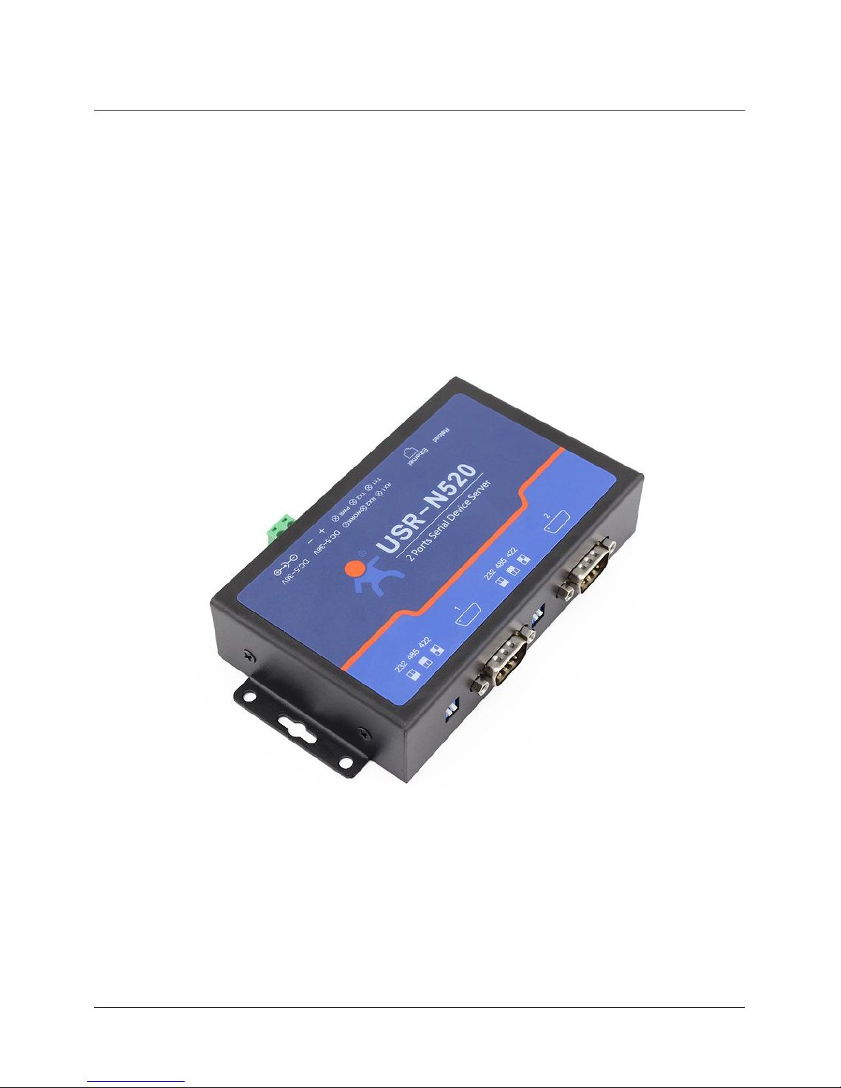
Double serial port server USR-N520 is used to realize data transparent transmission between TCP/UDP
data package and RS232/RS485/RS422 interface. Three in one serial port communicating code, support
common RS232/RS485/RS422 serial interfaces.
Any question during testing, please submit it on our technical support center: http://h.usriot.com
1.1. Hardware Testing Environment
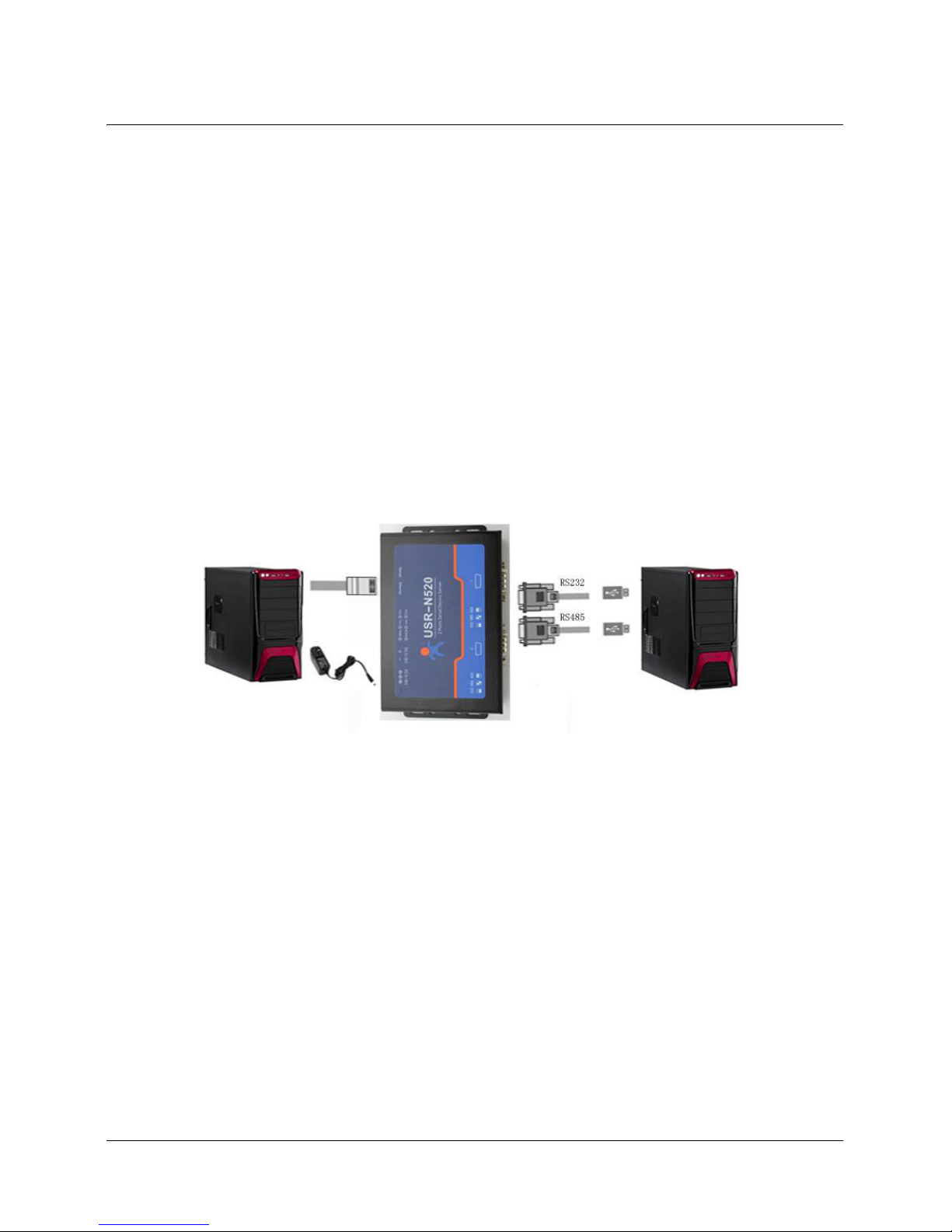
Connect the COM port of USR-N520 with PC’s via serial cable(or USB to serial cable).
Connect network interface between USR-N520 and PC via RJ45 cable.
Then supply power for USR-N520 with our AC adapter
The below picture will show you the connection.
Hardware Connection
Notes:
AC adapter and connection cable are provided by USR IOT.
RS232 is involved, no connection for RS485.
PCs in above picture is the same one.
1.2. Network Test Environment
Please check PC setting after hardware connection.
1) Disable PC Firewall and anti-virus software.
2) Disable the network card nothing to do with testing and just leave one local connection.
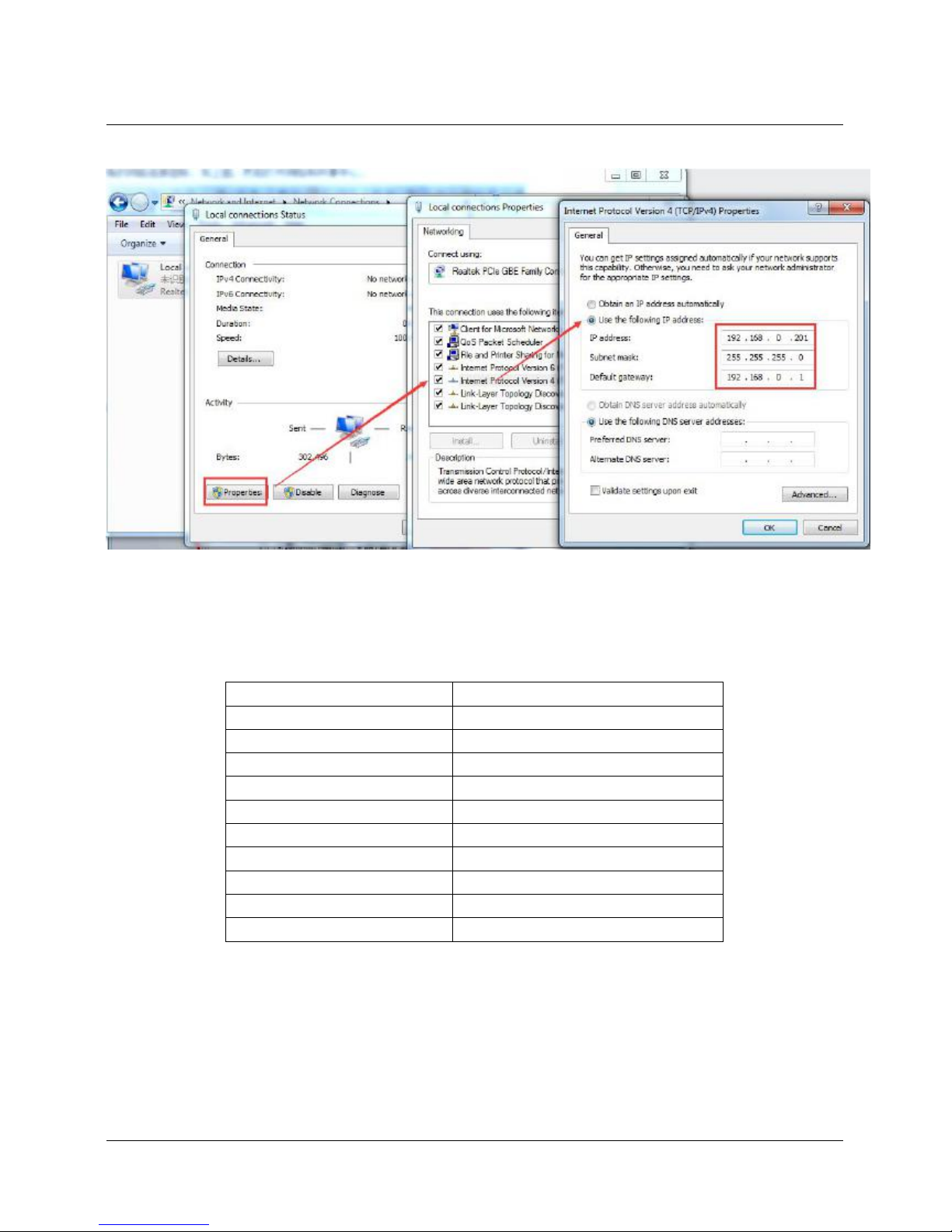
3) As for USR-N520 connect with PC directly, should set static IP for PC, which in the same network
Page 5
5 / 69
segment with USR-N520, like 192.168.0.201.
PC Local Connection Configuration
1.3. Default Parameter
Default parameter is as below:
User name
admin
Password
admin
IP address
192.168.0.7
Subnet mask
255.255.255.0
Default gateway
192.168.0.1
Default work dode of port 1
TCP Server
Default local port of port 1
23
Default work mode of port 2
TCP Server
Default local port of port 2
26
Baud Rate
115200
Parity bit/Data bit/Stop bit
None/8/1
1.4. Data Transmission Test
Data transmission test is based on the default parameters, please refer to the following steps:
1) Open test software “USR-TCP232-Test.exe”, and do hardware connection according to Chapter 1.1
Page 6
6 / 69
Hardware Testing Environment.
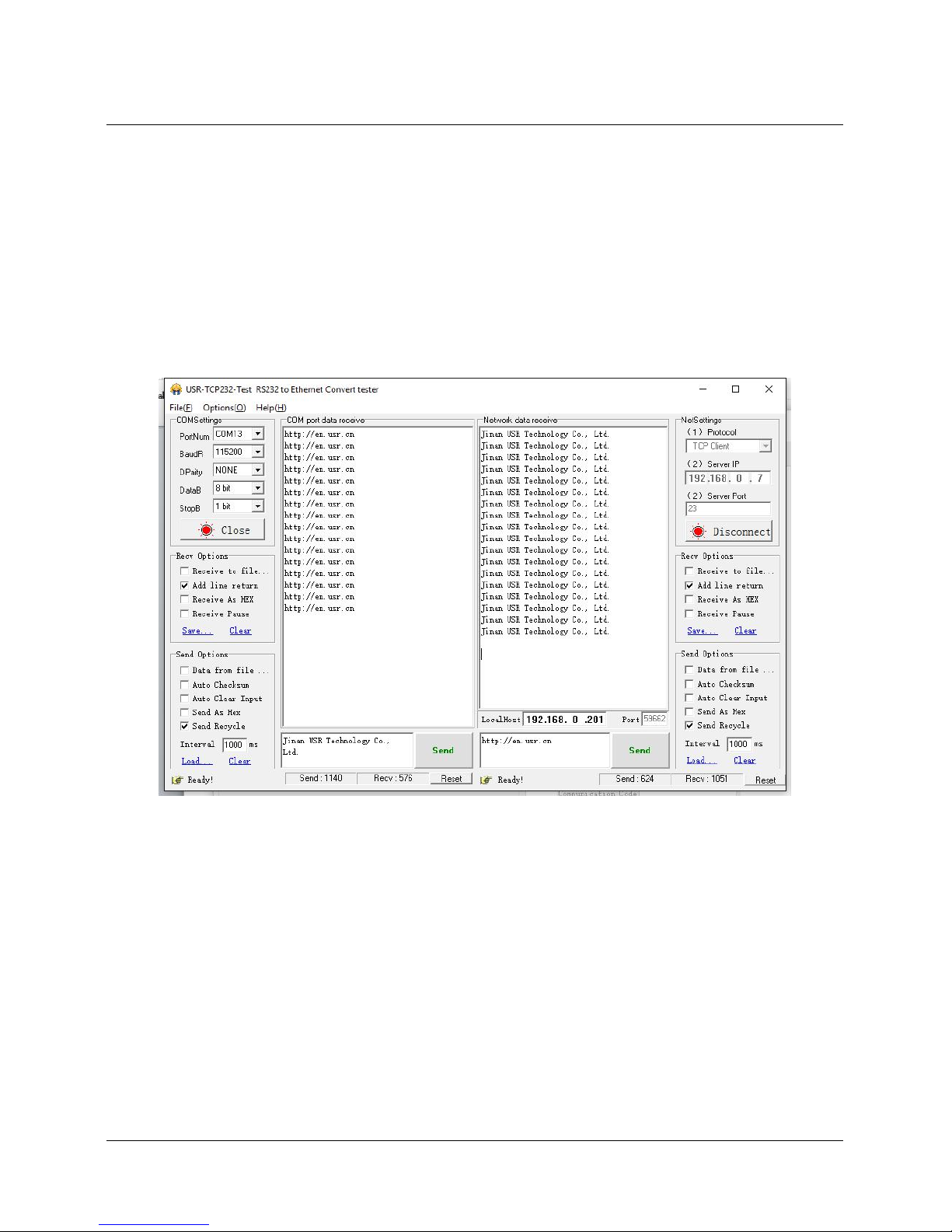
2) The right side is Network Settings: TCP Client, IP address: 192.168.0.7, port number: 23, click
“Connect” to build TCP connection.
The left side is Serial Settings: Baud Rate: 115200, Parity/Data bit/Stop bit: None/8/1,
Click “Open” to enable the COM.
Then we can test data transmission between COM and network.
Data from serial to network is: PC’ COM->USR-N520’ COM->USR-N520 Ethernet port->PC Network;
Data from network to serial is: PC Network->N520’ Ethernet port->N520 COM-> PC’s COM.
The below picture is for your reference:
Default Parameter Test
Page 7

7 / 69
2. Overview
2.1. Brief Introduction
USR-N520 is used to transmit data transparently between TCP/UDP data packet and RS232/RS485/RS422
interface. It carries ARM processor, low power, fast speed, high stability and two serial port can work as
RS232 or RS485 or RS422 serial interface which comfort to industrial standard.
2.2. Features
1. ARM base on Cortex-M4 kernel, and reliable TCP/IP protocol stack
2. Industrial working temperature range from -40C ~85C
3. Auto-MDI/MDIX,RJ45 port with 10/100Mbps
4. Support TCP server, TCP client, UDP, UDP server and HTTPD client work mode
5. One port corresponding to two socket
6. Support network printing via IP address
7. Function of Modbus gateway, modbus RTU to modbus TCP, modbus multi-host Polling
8. Two serial port, each port can work as RS232 or RS485 or RS422 and work individually
9. Distinguish which serial port connect to device via port number
10. Support virtual serial port and provide corresponding software USR-VCOM
11. Serial baud rate from 600bps to 230.4K bps; Check bit of None,Odd,Even,Mark and Space
12. Support static IP, DHCP/DNS and search devices within network through UDP broadcast.
13. Provide serial and network setting protocol, TCP/IP socket example code such as VB, C++
Delphi,Android,IOS
14. Built-in web page; Customized web page is acceptable
15. Reload button,one key to restore default settings
16. RJ45 with Link/Data indicator light,built-in isolation transformer and 2 KV electromagnetic isolation
17. The global unique MAC address bought from IEEE, also user can define MAC address
18. Upgrade firmware via network
19. Support web port revise (80 by default)
20. Keepalive, detect dead links and reconnect rapidly
21. Support account and password, used to page log in and network settings safely
22. Support one channel Web socket,realize bidirectional transparent transmission between web page
Page 8
8 / 69
and serial side
23. Power supply in two mode, DC adapter or 5.08-2 terminal pin
24. Communication indicator light of two serial port: RX/TX
25. UPD broadcast function, can receive/send data to all IP in the same network
2.3. Basic Parameter
Parameter
Value
Input Voltage
DC5~36V
Working Current
90mA@5V
Operating Temp.
-40~+85°C
Power
<1W
Storage Temp.
-45~105°C, 5~95%RH
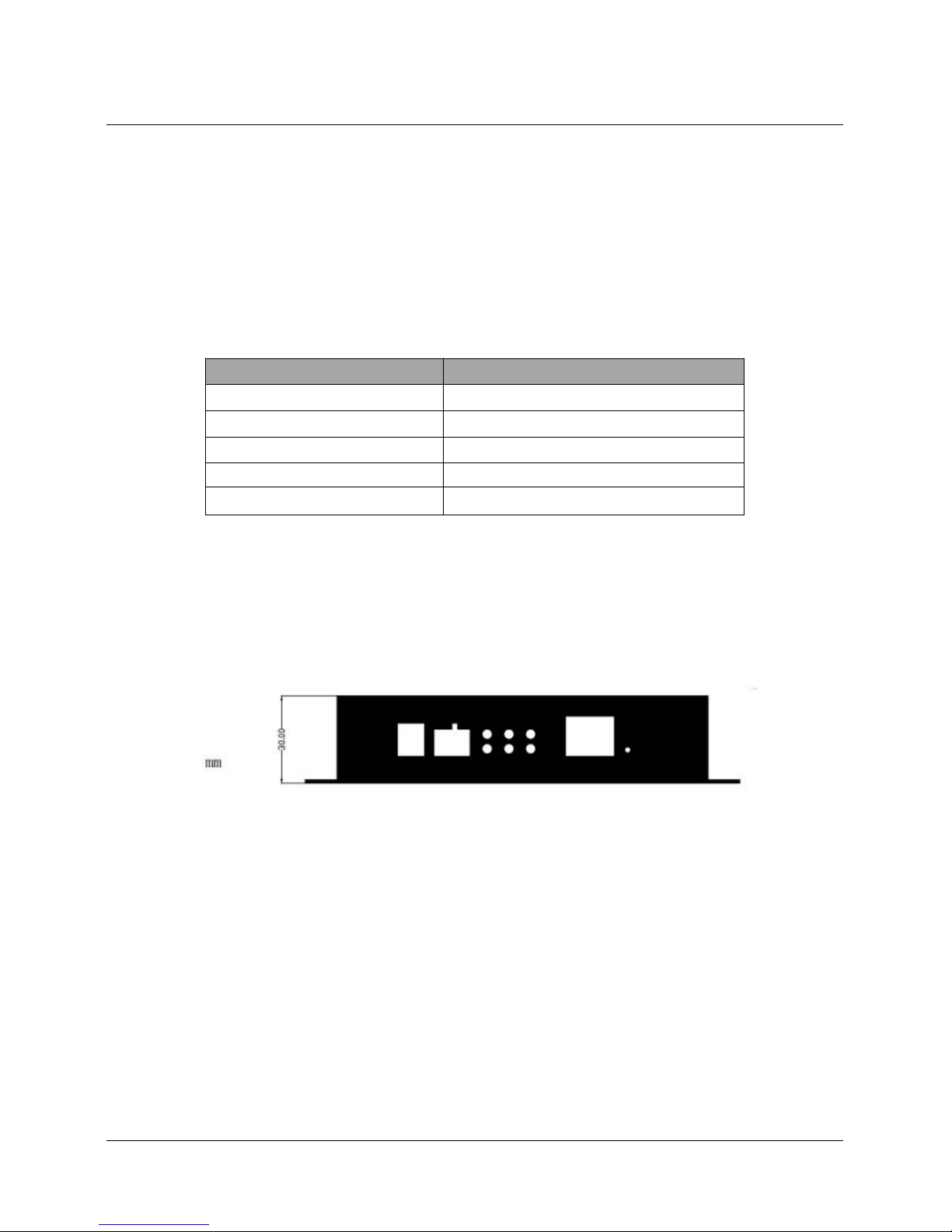
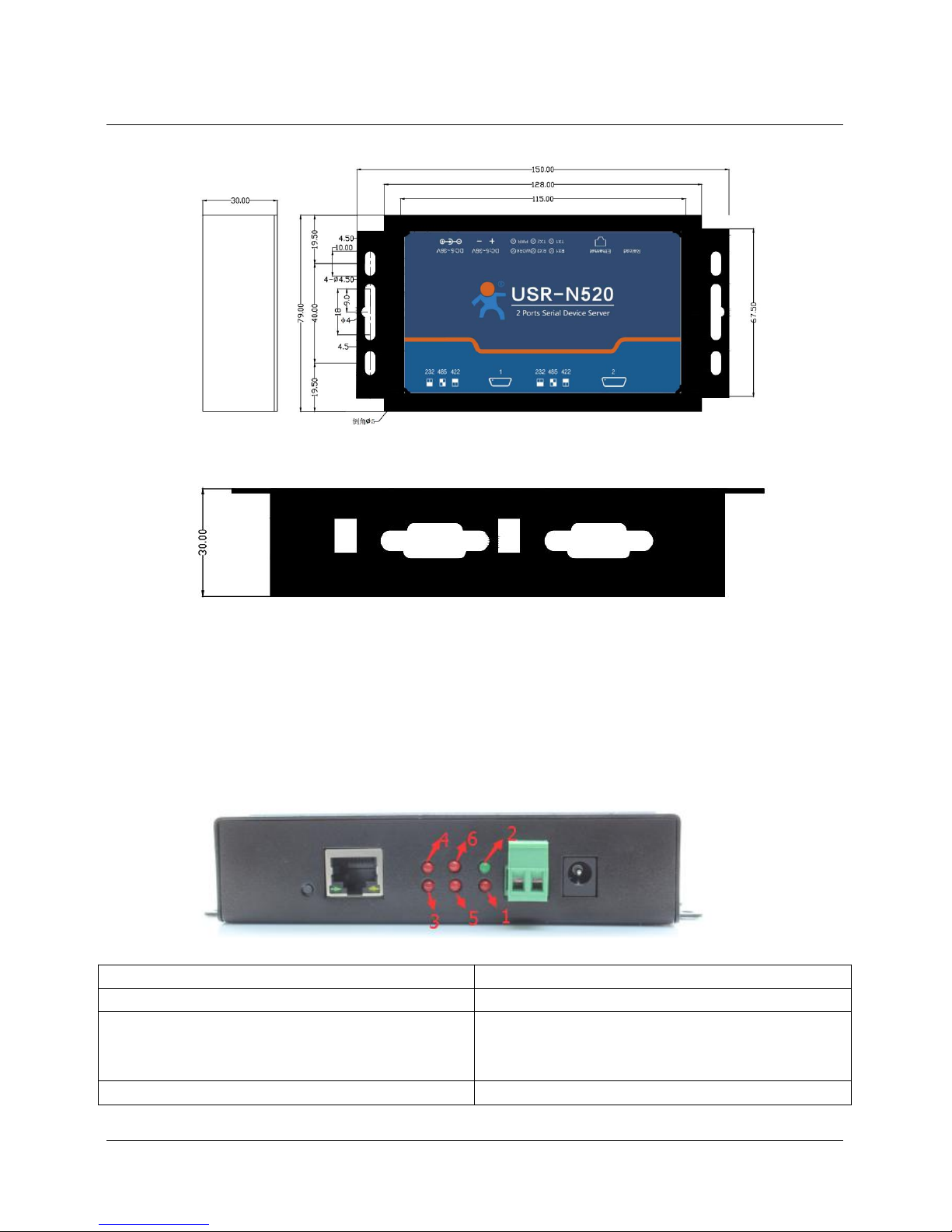
2.4. Dimension
Page 9
9 / 69
2.5. Indicators and Dial switch
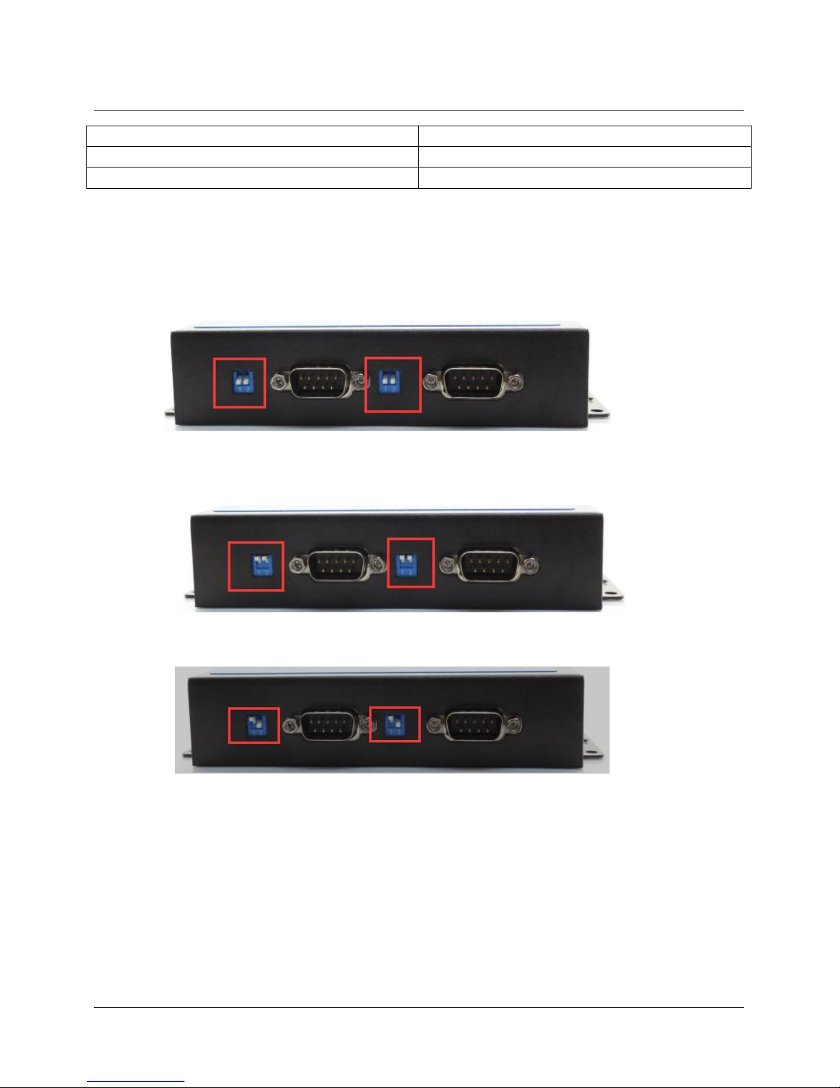
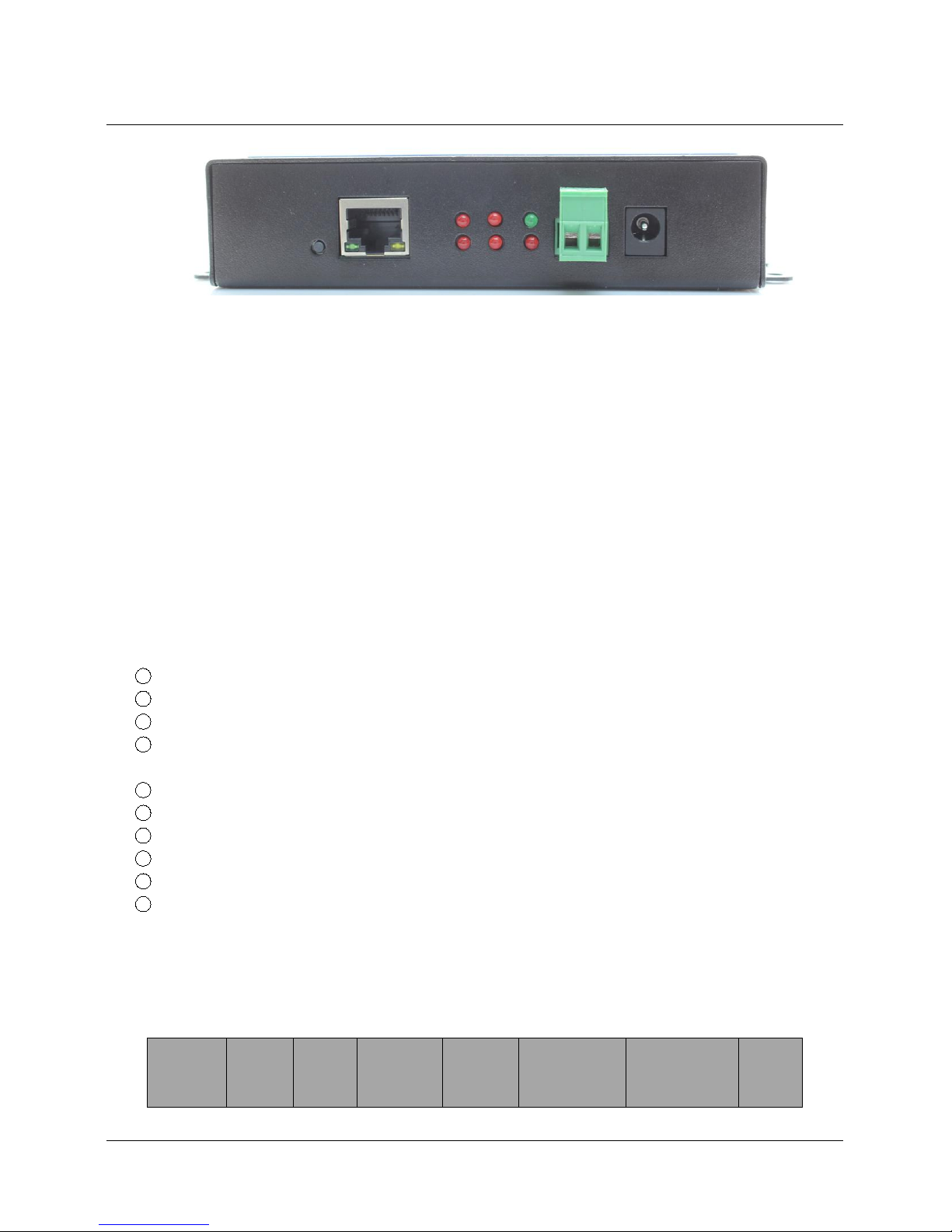
<Indicator light>
Indicator
Description
①Power
Indicate power. It is on when power is supplied
②Work
Indicate working status. It twinkles when N520 works
well. If it is on or off for a period, N520 works
improperly, you should cut the power and restart.
③TX1
It twinkles when port 1 sends data
Page 10
10 / 69
④RX1
It twinkles when port 1 receive data
⑤TX2
It twinkles when port 2 sends data
⑥RX2
It twinkles when port 2 receive data
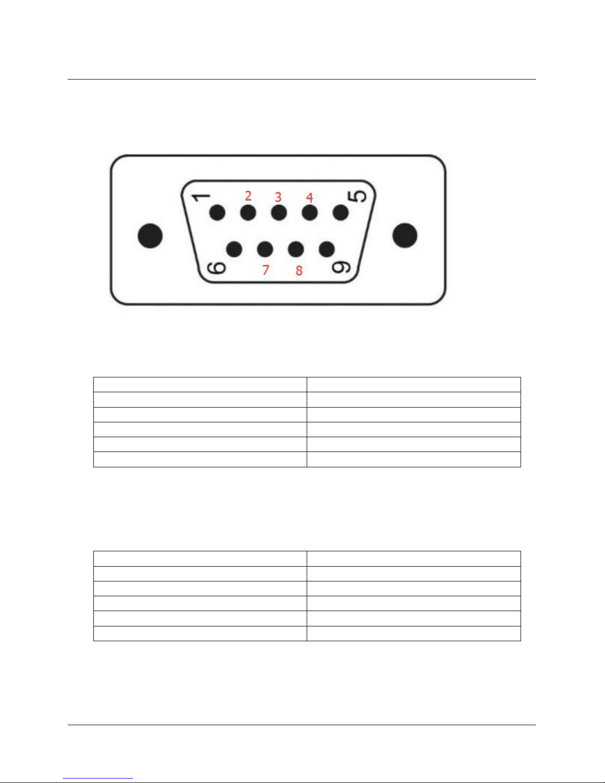
<Dial Switch>
For RS232 port, dial switch are down, such as the below picture.
For RS485 port, dial switch are up, such as the below picture.
For RS422 port, dial switch on the left are up, dial switch on the light are down,
Page 11
11 / 69
2.6. DB9 Pin Definition
For RS232 port, pin definition is as below
For RS485 port, pin 3 works as “B(-)”, Pin 7 works as “A+”
For RS422 port
Pin
Definition
2
RX, pin of receives data
3
TX
5
GND
7
RTS
8
CTS
Pin
Definition
2
RX+, pin of receives data
3
RX-
5
GND
7
TX+
8
TX-
Page 12
12 / 69
3. Product Function
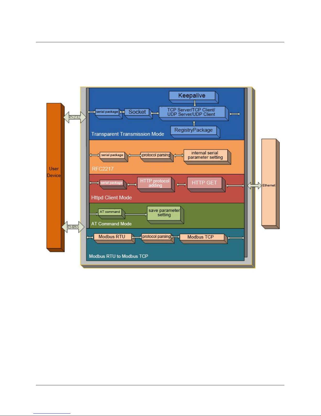
The following is function diagram of USR-N520
USR-N520 Function Diagram
Each serial port corresponds to two socket: socket A and socket B. Socket B can be opened or closed.
3.1. Socket A Communication
3.1.1. TCP Client Model
4.1.1 TCP Client Mode
1) Different from UDP mode, in this mode, connection has status of disconnection and remaining.
Page 13
13 / 69
Connection is still remained although USR-N520 does not send data.
2) Identify disconnects. After connection built, it sends keepalive searching packet every 15 seconds.
Once there is an interrupt, it can be detected rapidly then make USR-N520 disconnect from former
connection and reconnect.
3) It will connect to same source port when USR-N520 try to connect server and local port is not “0”.
4) It supports USR Synchronous baud rate (Similar RCF2217), which can revise USR-N520’s serial
parameter as baud rate accordingly. This function should be combined with USR-VCOM.
5) Under the same LAN, USR-N520 must be in the same network segment then can communicate. If
not, USR-N520 must be set with right one.
6) Support USR Cloud.
7) Support Modbus TCP function.
8) USR-N520 work as TCP Client, it connects to TCP server, Destination IP and port should be cared.
The IP can be device with same LAN, also can be different LAN or cross public network. If it
connects to server cross public network, the server should have public IP.
9) USR-N520 work under TCP Client, It connects to the target IP/Port automatically,will not accept
other connection request.
10) As TCP Client, need to set USR-N510’s local port number to be “0 then it can visit server with
randomized port number, so that it can solve unsuccessful re-connection in case server judge
connection status abnormally and shield USR-N520 re-connection request.
11) Test Example
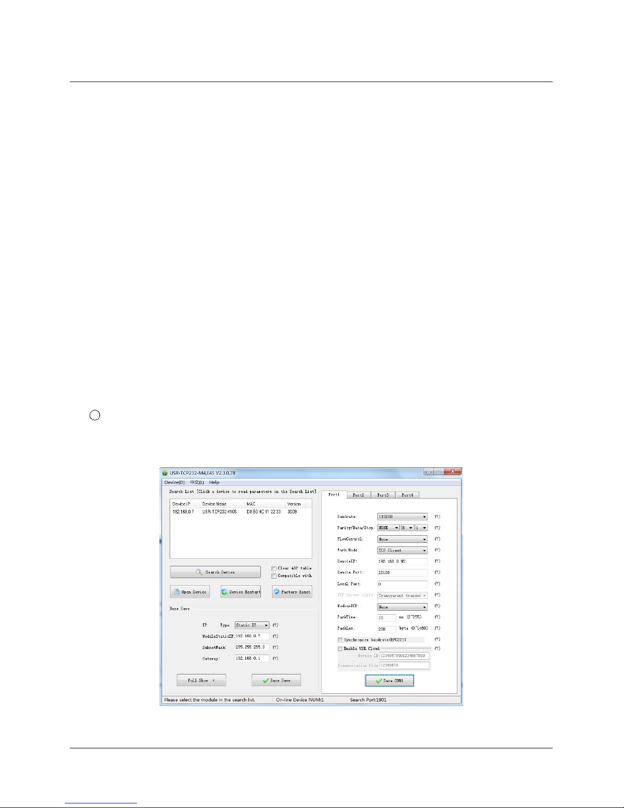
1 Open “USR-TCP232-M4_E45 setup” software.
Set USR-N520 as TCP Client, Destination IP: 192.168.0.95. Destination port:20108.
Click “Save COM1”, and search USR-N520.
Then check if the parameters are correct when USR-N520 is found.
Configuration
Page 14
14 / 69
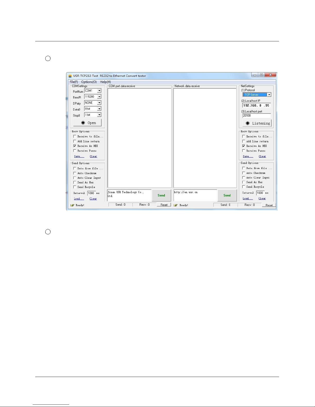
2 Open “USR-TCP232-TEST” software:
Need to connect to PC’s TCP Server, its IP: 192.168.0.95, Port number: 20108, Click “Listening”
TCP Client Test Screen shot
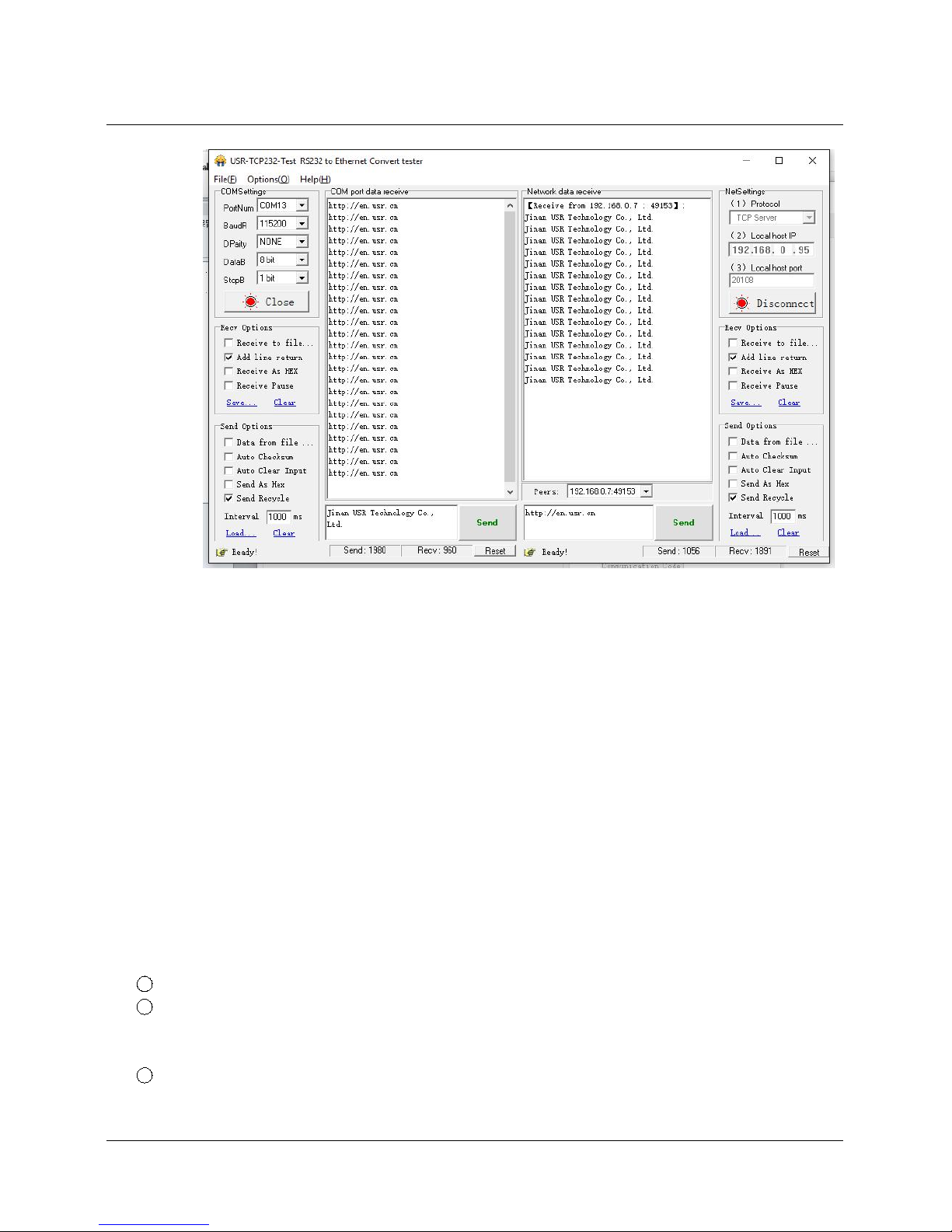
3 USR-TCP232-TEST software:
Configure serial parameter. Click to open the port. Test software network part shows connection
message:192.168.0.7:49153(port# assigned randomly). Click “send”, you can gain data from each
side.
Page 15
15 / 69
TCP Client Software Configuration
3.1.2. TCP Server Mode
1) Different from UDP, in this mode, connection has status of disconnection and remaining. Connection
is still remained although USR-N520 does not send data.
2) USR-N520 listens to local port set firstly, respond and build connection when there is a connection
request. Serial port will send data to all client which connected with USR-N520 at the same time
once serial port received data.
3) It supports USR Synchronous baud rate (Similar RCF2217), which can revise USR-N520 serial
parameter as baud rate accordingly. This function should be combined with USR-VCOM.
4) It support 8 clients connections at max. (32 clients will be improved in the following.)
5) Support Modbus TCP function.
6) Under TCP Server mode, USR-N520 listens to local port actively and will not monitor connected IP
and port. When the 9thclient is connected, the oldest one will be ticked.
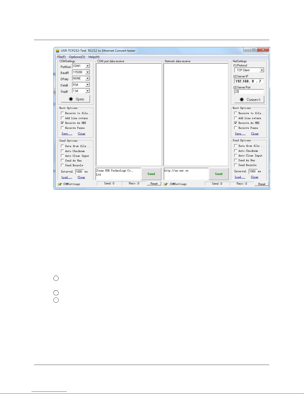
7) Test Example
1 Set USR-N520 as TCP Server Mode, local port 23, same as default.
2 Open ”USR-TCP232-TEST” Software, on the side of NetSettings:
Protocol: TCP Client
Server IP/Port: the same value as the default parameter of N520
3 Click ”Connect” to test data transmission.
Page 16
16 / 69
TCP Server Test Screenshot
3.1.3. UDP Client Mode
1) It subjects to UDP protocol, no connection, just only sending data.
2) USR-N520 only communicate with destination port of IP. Otherwise, the data cannot be received.
3) Under this mode, destination Address is 255.255.255.255, then it can make UDP broadcast and
receive broadcast data. Broadcast within segment as 192.168.0.255, it can be sent but cannot be
received currently.
4) Under UDP Client/ UDP Server mode, host PC allow data length 1460 bytes at max to USR-N520.
5) Test Example:
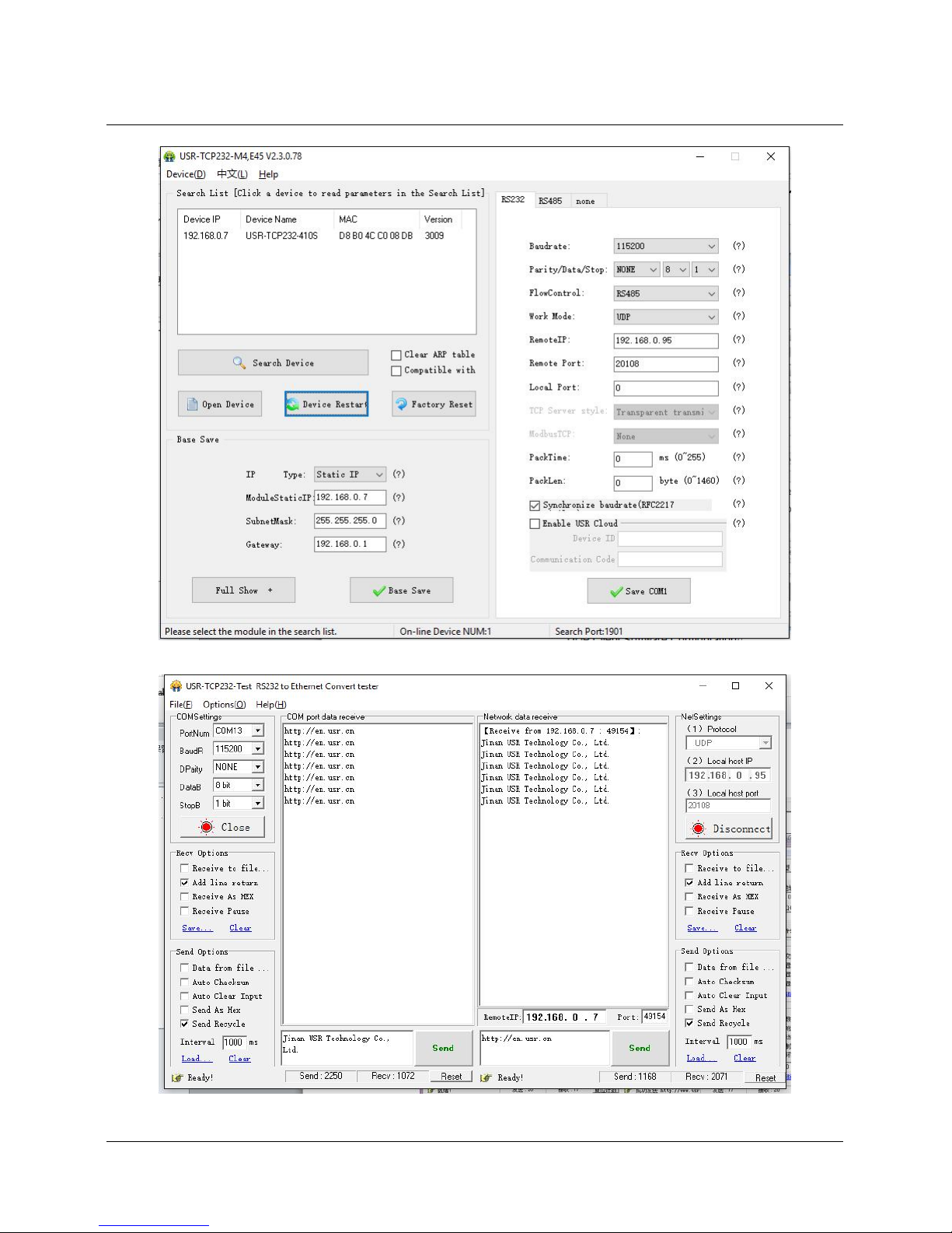
1 Open USR-TCP232-M4, E45 Setup Software: build a UDP firstly. PC’s IP is 192.168.0.95. Port
to be listened is 20108.
2 Open USR-TCP232-TEST Software: set USR-N520 as UDP Client, destination port: 20108.
3 Click “Send” at serial side. Remote IP and port becomes USR-N520’s after receiving the data.
Then click “Send” in network part and send data to COM.
Page 17
17 / 69
UDP Client Software Configuration
UDP Client Testing Screenshot
Page 18
18 / 69
3.1.4. UDP Server Mode
1) Base on normal UDP, it doesn't verify source IP address. Every time USR-N520 receive one UDP
data packet, it changes destination IP to where data comes and it sends the data to the IP and port
which communicate latest.
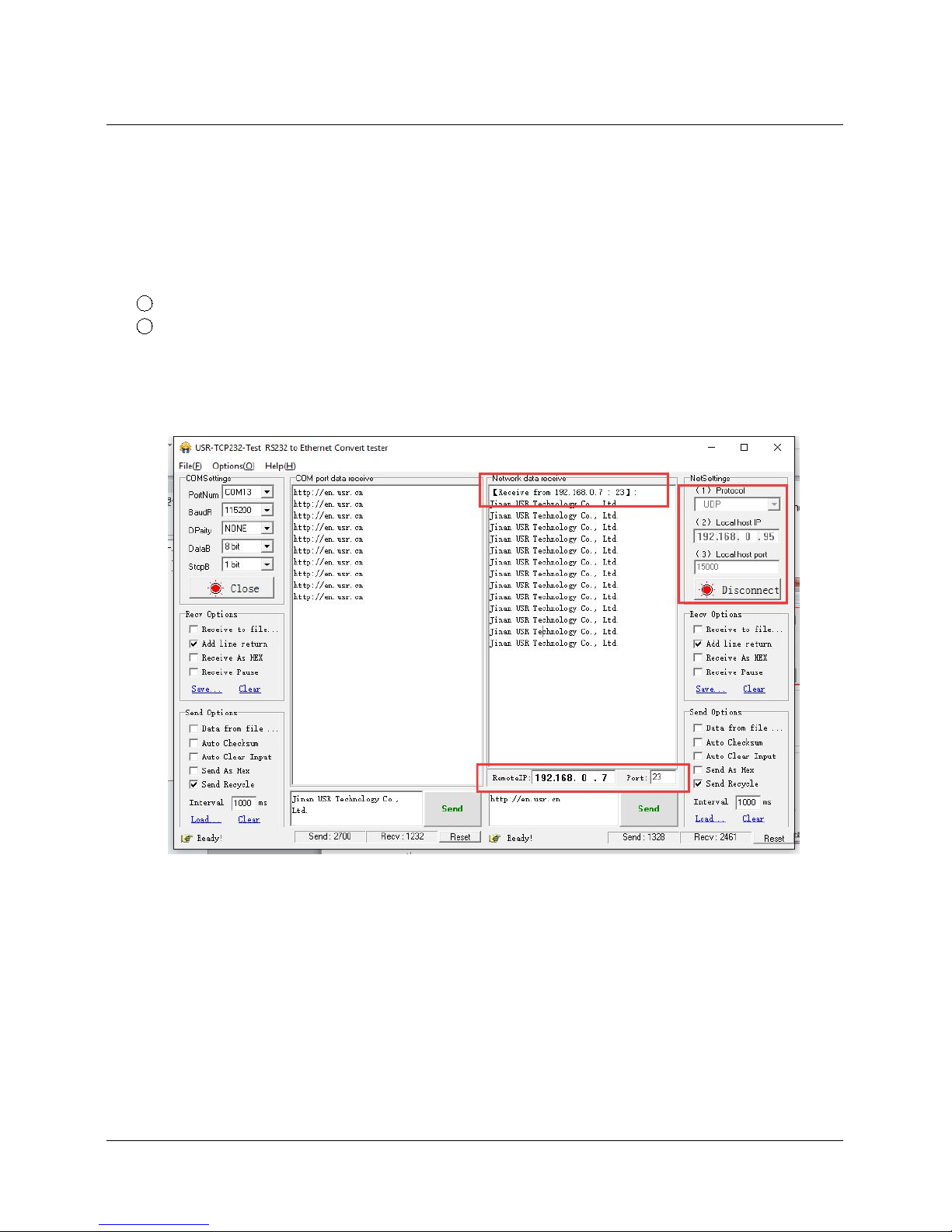
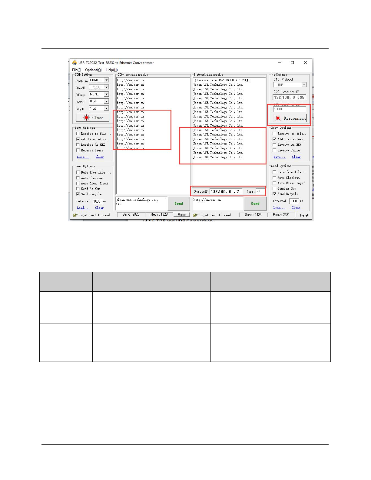
2) Test Example:
1 Open “USR-TCP232-M4_ E45 Setup” Software: Set USR-N520 as UDP Server, local port: 23.
2 Open “USR-TCP232-TEST” Software twice. Set work mode as UDP, remote IP and port same with
USR-N520’.
Click “Send” then the COM receive data.
Click “Send” at serial side, only the software communicate latest can receive the data.
UDP Server Test Screenshot
Page 19
19 / 69
UDP Server Test Screenshot
3.1.5. TCP and UDP Comparison
TCP
UDP
Advantages
Stable, no loss
Reliable connection mechanism
Resend after data sending fails
No Connection mechanism, simple, flexible
Suit for small packet and high frequency
Accurate data sending interval
Disadvantages
Long packet starting
Jam for small packet and high frequency
Inaccurate interval resulted from check
and resend mechanism
More less under bad network environment
3.1.6. HTTPD Client
It is used to transmit data from USR-N520 to HTTP server or gain data from HTTP server.
USR-N520 can handle complex HTTP protocol so user just do programming for serial, and not need to worry
about HTTP.
When USR-N520 sends data to HTTP server via serial port, it only needs to send the header of requested
data; All the returned data will be transmitted by USR-N520, user need to analyze the packets.
Page 20
20 / 69
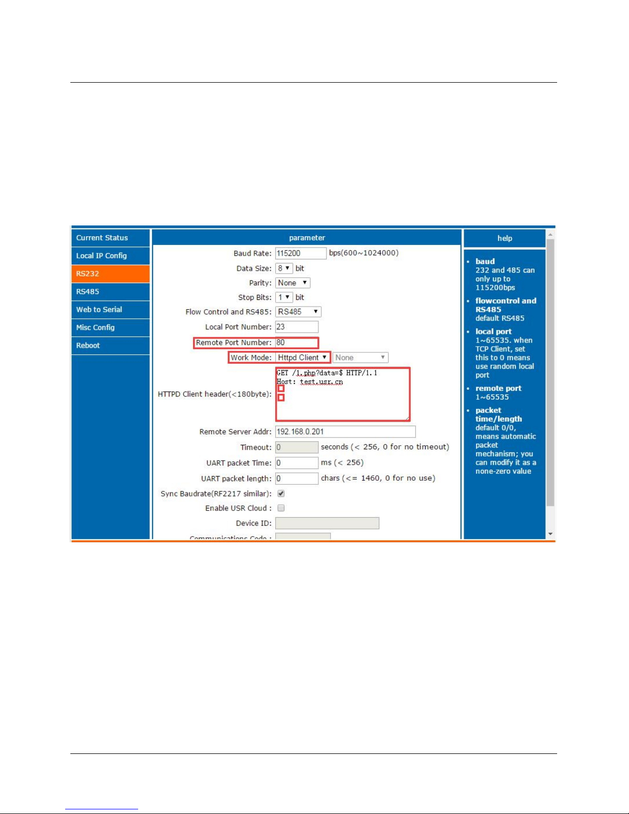
Test Example:
1) Entry http://192.168.0.7 (N520’s IP) to open its web page
1. SetUSR-N520 as HTTPD Client.
2. Set HTTPD packet Header.
HTTPD Client Web page Configuration Screen shot
<Note>:
HTTPD Client only support GET to request HTTPD Server. POST will be available in the following.
GET/ is fixed packet header.
1.php?data= is the visited/submitted the page
$ stands for data sent by serial (Serial port does not need to send “$”)
HTTP/1.1 is requested protocol.
Host is means requested IP address/ domain.
Enter twice
Page 21
21 / 69
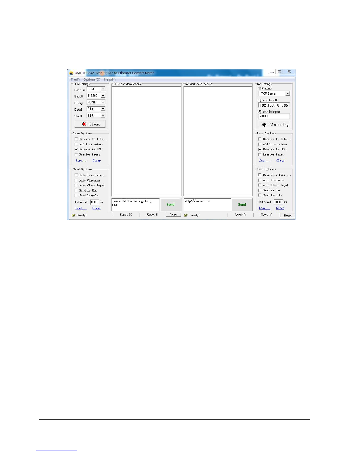
2) Save the parameters and restart USR-N520.
3) Open serial port to send data, then the data can be submitted onto our web page server.
HTTPD Client Test Screenshot
3.2. Socket B Communication
USR-N520 support double socket communication mode, socket A and socket B. One serial port
corresponding to two socket communication mode can be realized through setting the parameter of socket B.
But socket B is only used for transparent transmission and only worked as TCP client or UDP client.
Set USR-N520 as double socket communication mode, the data of serial port will be transparently
transmitted to socket A and socket B at one time. When data comes from socket A and socket B
simultaneously, USR-N520 will transmit the data of socket A to serial port firstly, and then transmit the data of
socket B once the data of socket A finished.
Communication example:
1. Set the parameter of socket A and socket B by web page
Page 22
22 / 69
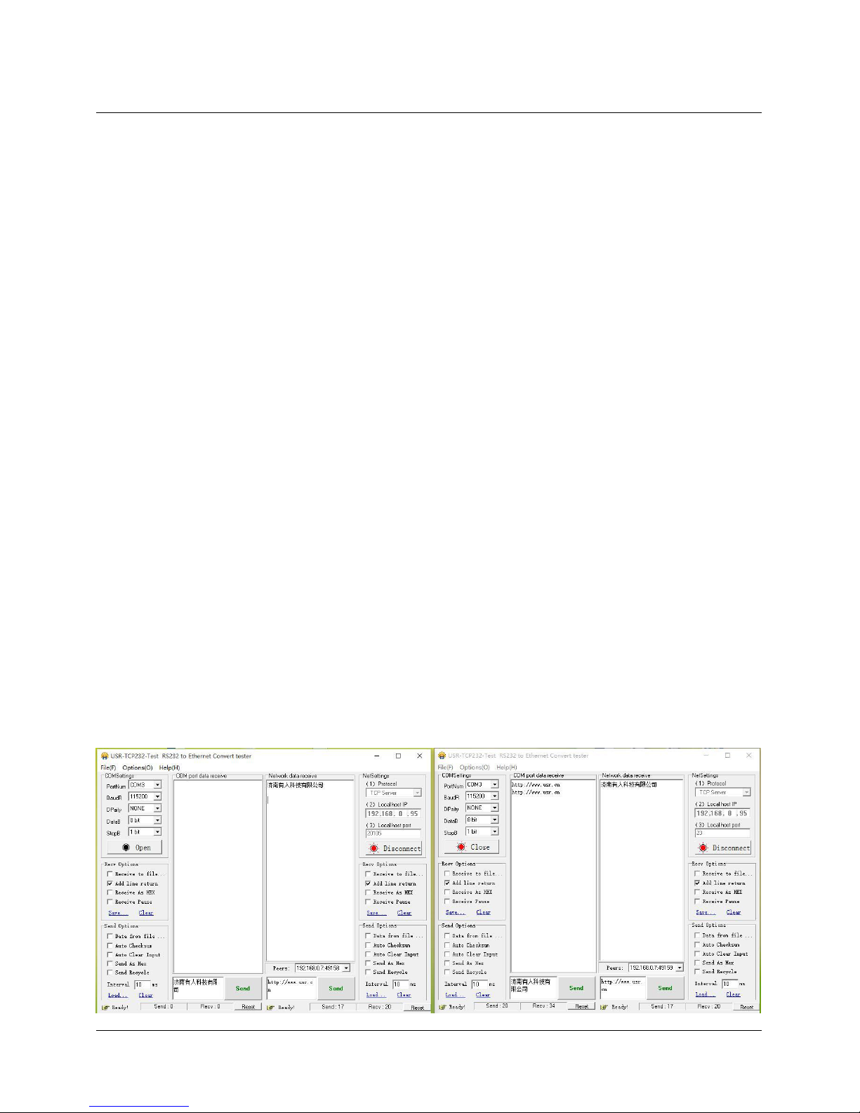
2. Set up socket A and socket B by “USR-TCP232-Test.exe”, and open serial port which connects to server.
3. Click “Send” on the software, data will be transmitted from socket A and socket B to serial port.
Page 23
23 / 69
3.3. USR-VCOM Application
It solve the transmission problem of traditional device PC software working as COM. USR-VCOM
(Virtual com software) support receiving data from set COM and send serial data out as network.
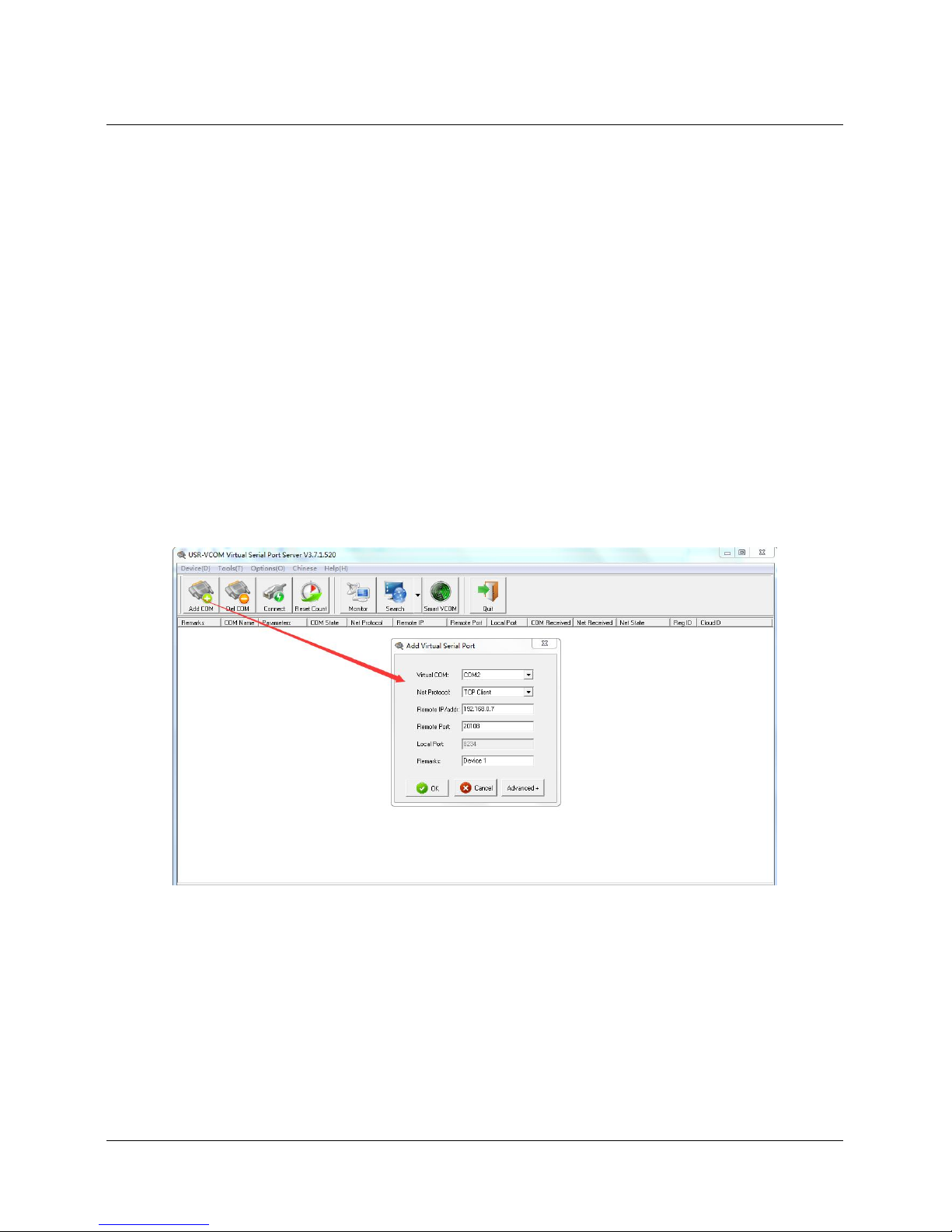
How to connect USR-N520 with Virtual COM:
1. Set USR-N520 as TCP server
2. Open USR-VCOM software, click “Add COM’ and select COM2 (Avoid existed COM).
Net Protocol: TCP Client
Remote IP and port is the same one with USR-N520
Remarks: Can write the name of device
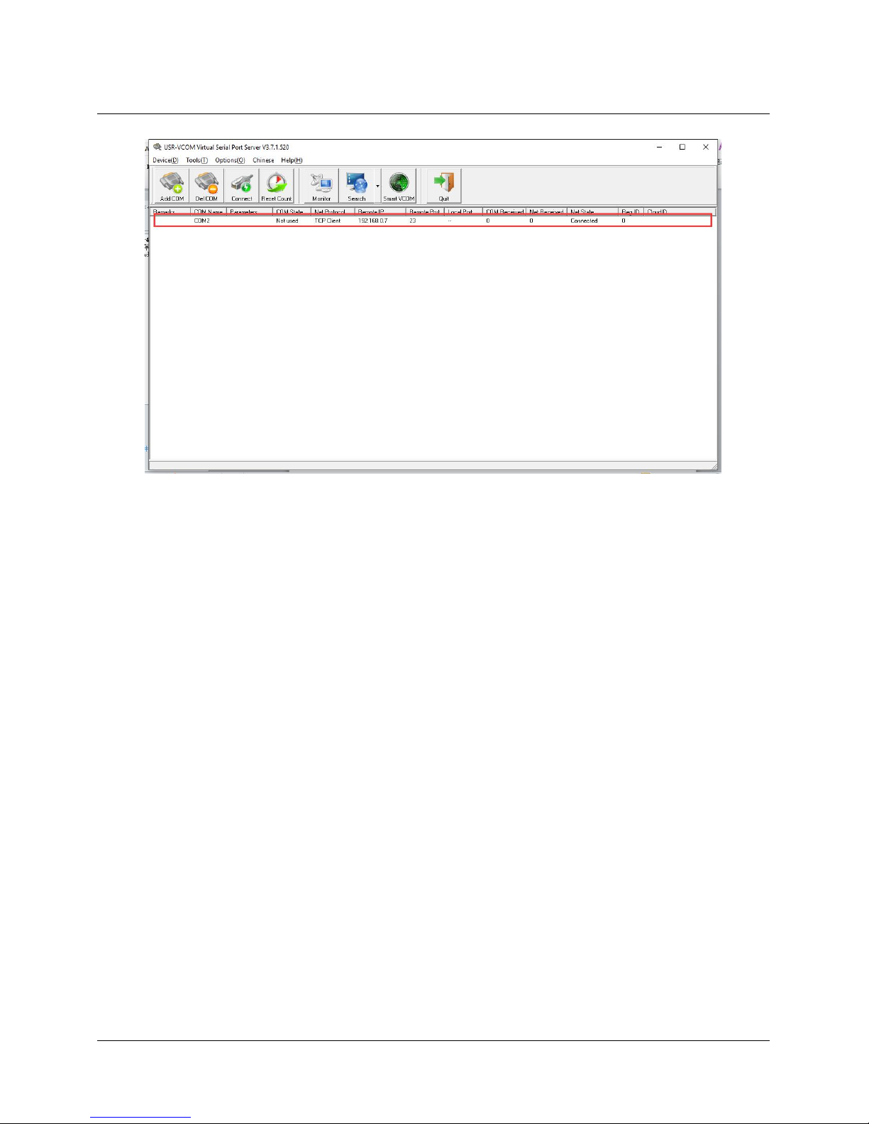
3. Click “OK’ to check whether connection is built. “Connected” sow ready for data transmission.
More details, please refer to http://www.usriot.com/?s=vcom
USR-VCOM Add a COM
Page 24
24 / 69
USR-VCOM Build Connection
3.4. Modbus Gateway
3.4.1. Transmit modbus protocol in transparent mode
USR-N520 supports the transmission of modbus protocol in transparent mode
3.4.2. Modbus RTU to Modbus TCP
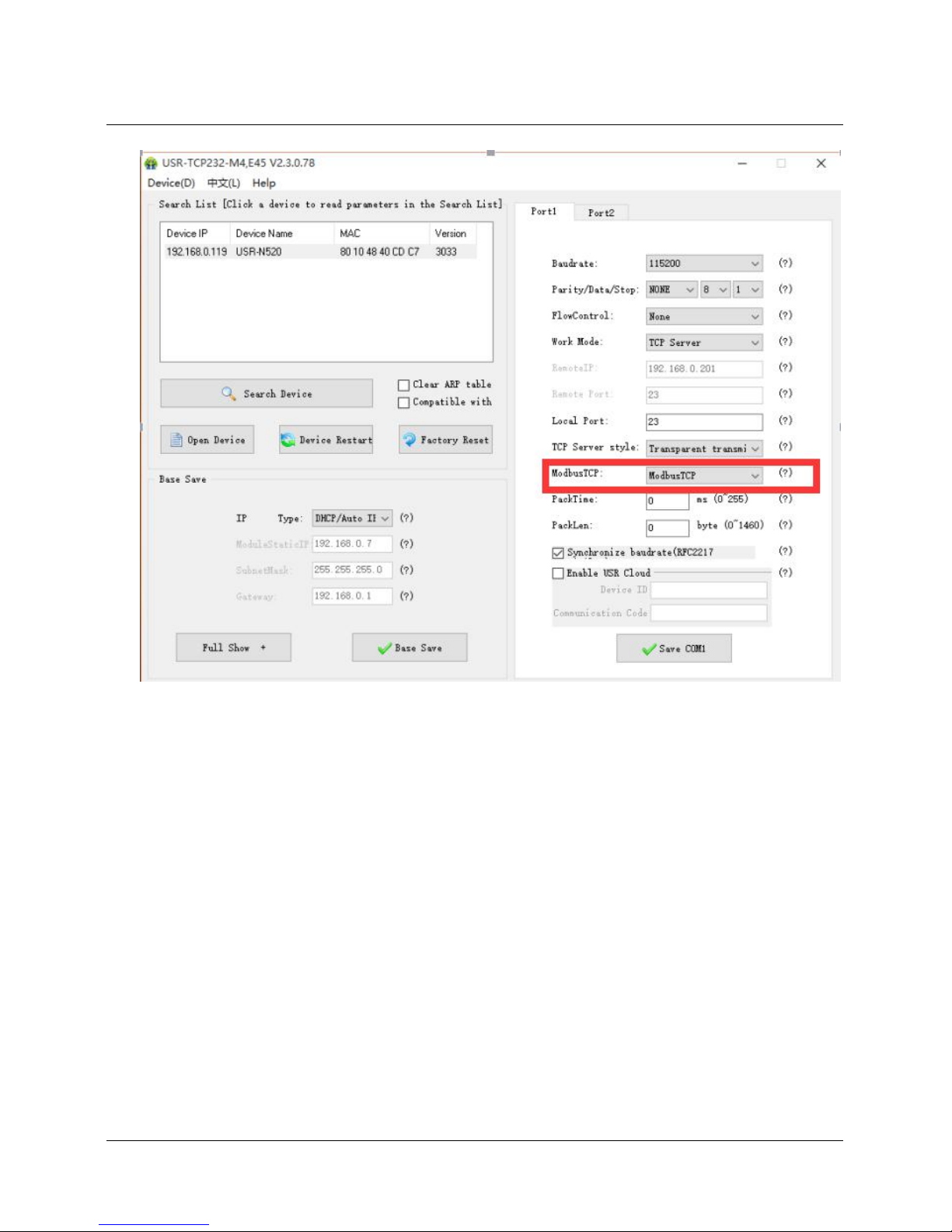
USR-N520 support Modbus RTU to Modbus TCP, setting method as below:
1. Open USR-TCP232-M4,E45 Setup Software, set USR-N520 as TCP server or TCP client.
2. Select “ModbusTCP” on the red color
3. Click to save the parameter
Page 25
25 / 69
Modbus TCP Configuration
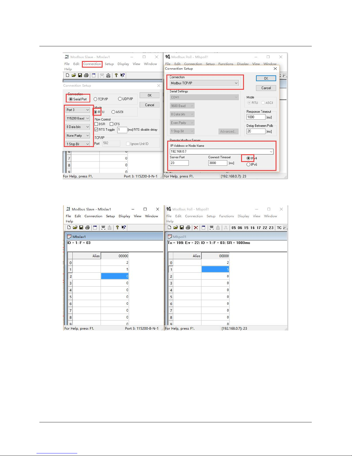
4. Check and verify Modbus RTU to Modbus TCP through modbus Poll and Modbus Slave
5. Setting modbus software is as below:
Page 26
26 / 69
6. Click OK once configuration finished, update the data of modbus slave and modbus data will also be
updated.
3.4.3. Modbus Active Query Function
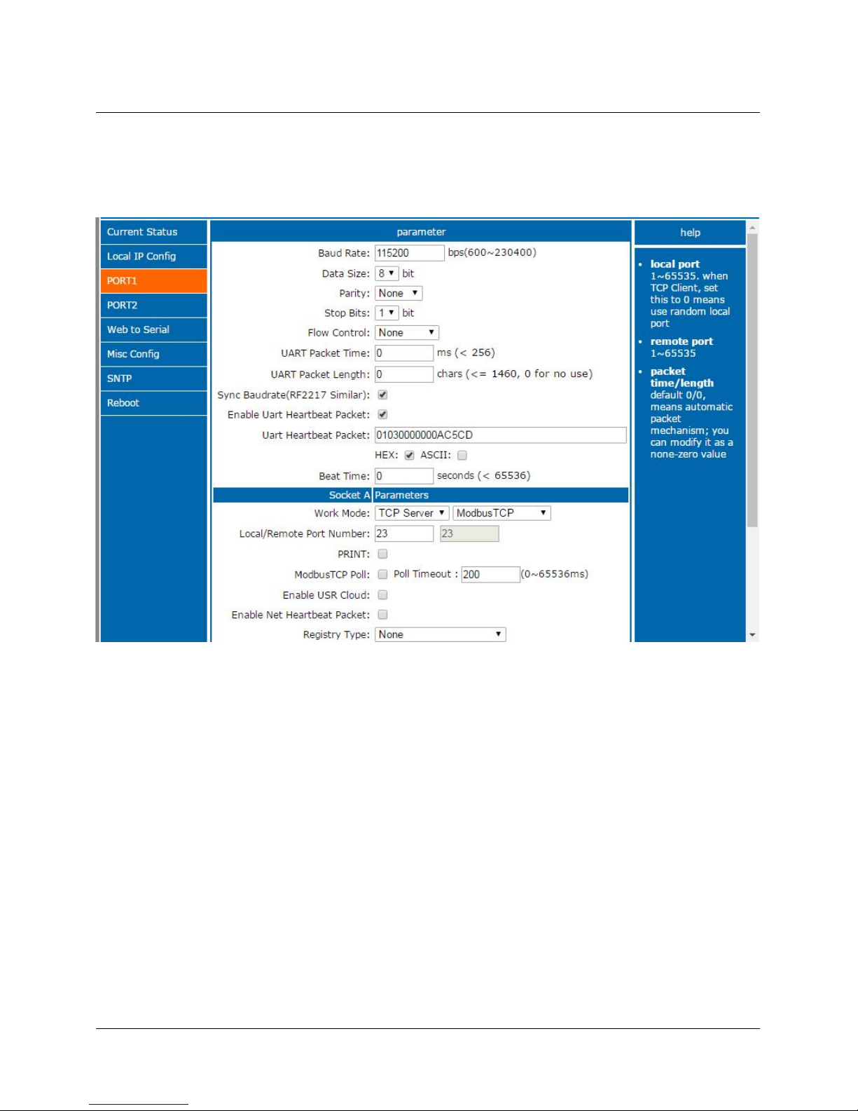
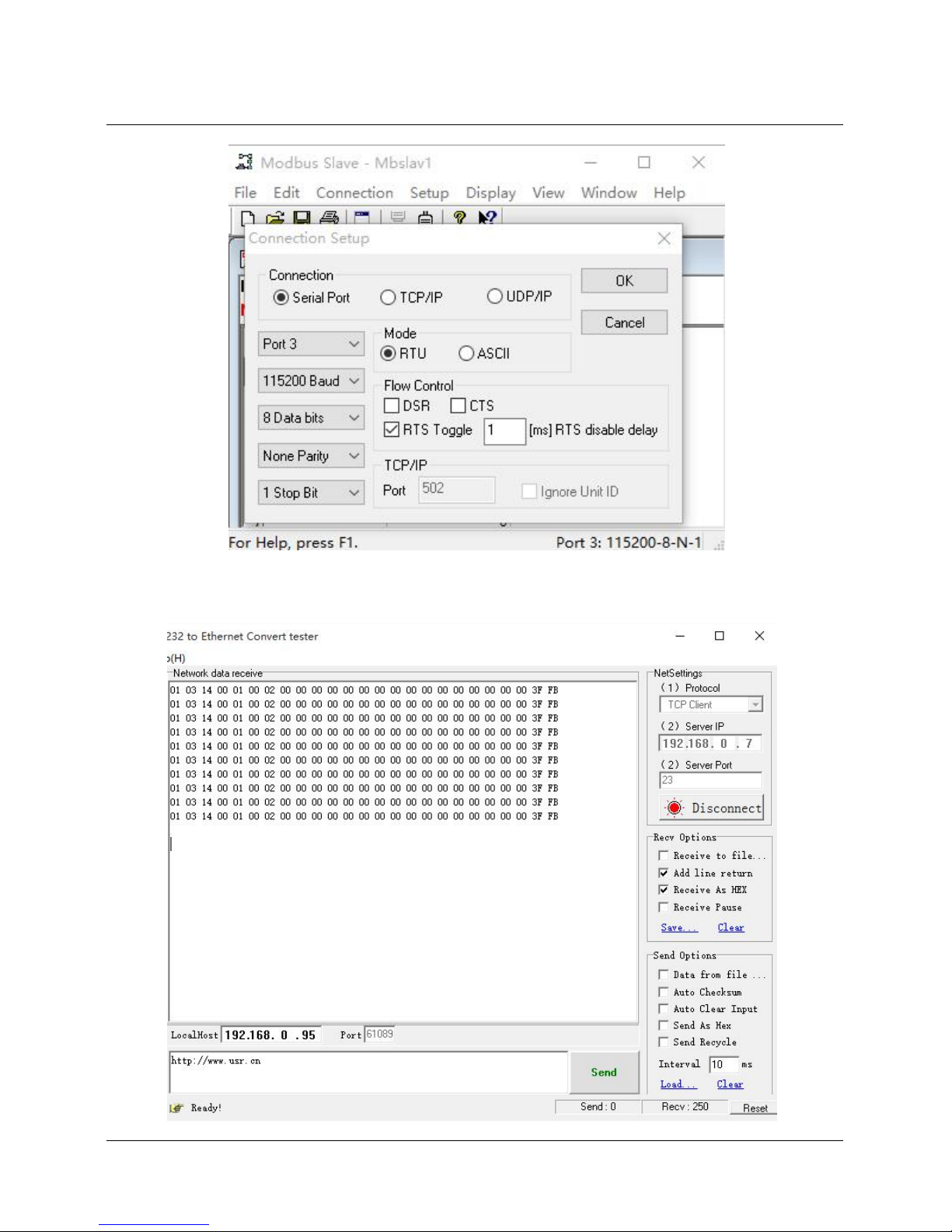
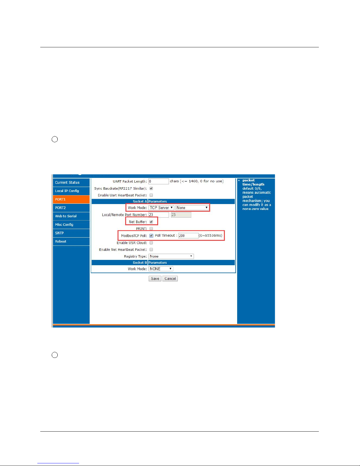
Modbus active query function can be realized through the serial heartbeat packet function of USR-N520.
1. Open serial heartbeat packet function via web page, query command is heartbeat packet data, example:
Page 27
27 / 69
2. Set modbus slave software, refer to the following:
Page 28
28 / 69
3. Return result for query command is as drawing:
Page 29
29 / 69
3.4.4. Modbus Polling Function
USR-N520 support modbus polling function under TCP server mode. Set USR-N520 as Modbus Poll,
support multiple host polling to check parameter.
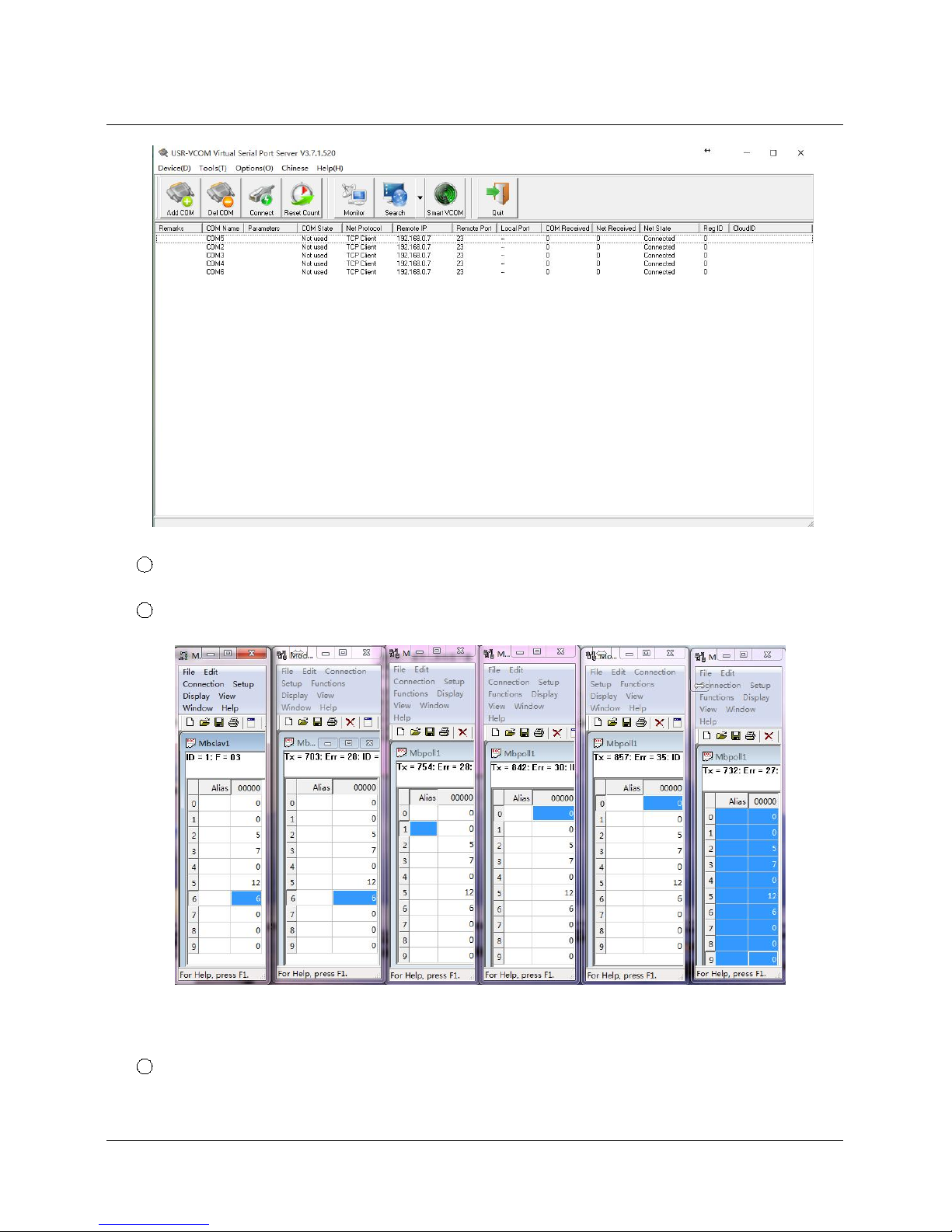
1. Multiple host polling is realized through virtual com.
1 Set parameter of USR-N520 via web page, make sure to select ModbusTCP Poll and set overtime
2 Open virtual com softarae to setup servel ports and connects to USR-N520
Page 30
30 / 69
3 Open modbus slave software, choose the serial port which connected with USR-N520. Run modbus
Poll software and make port-forwarding with this serial port.
4 The value of modbus poll will also be changed when you revise the value of modbus slave.
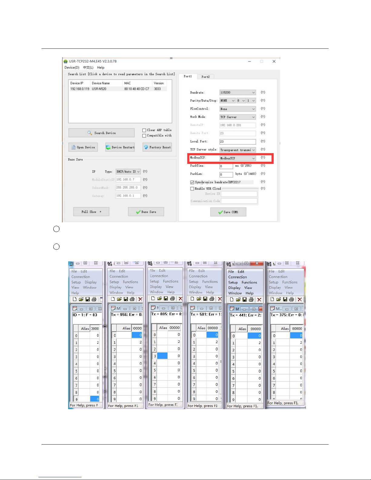
2. Conduct Modbus Polling through Modbus TCP to Modbus RTU
1 Set USR-N520 via software, select Modbus TCP
Page 31
31 / 69
2 Open modbus slave software, choose the serial port which connected with USR-N520. Run modbus
polling softare to select network mode and connect with USR-N520.
3 The value of modbus poll will also be changed when you revise the value of modbus slave.
3. Modbus Polling supports 8 host query for the most, more in the near future. Need set polling time properly
when using modbus polling function. If polling interval is too shot and baud rate is too low for the process of
Page 32

32 / 69
polling command which might lead to conflict between command circle and polling time.
3.5. Value-added Functions
3.5.1. DHCP
DHCP is obtaining IP address automatically. USR-N520 IP obtaining have 2 types: DHCP and static IP. It is
static IP192.168.0.7 by default.
DHCP is effective after change to DHCP and restart. When USR-N520 connects to router or device
assigning IP, it require IP address from host within network, which takes about 5-15 seconds.Then you can
search N520’s IP address. It is convenient for setting different IP address in different environment.
<Note> Don’t set DHCP when USR-N520 connected to PC directly because generally PC don't have the
ability of assigning IP. Otherwise, USR-N520 cannot transmit data normally, but wait for IP.
3.5.2. DNS
USR-N520 access the domain name or dynamic domain name when work under Client mode. The length
of domain name must be less than 30 bytes .USR-N520 will analysis the domain name constantly if cannot
connect to destination server.
When server’s IP address is dynamics, DNS make USR-N520 ’ parameter no changes if according IP
doesn't change no matter how server IP address changes.
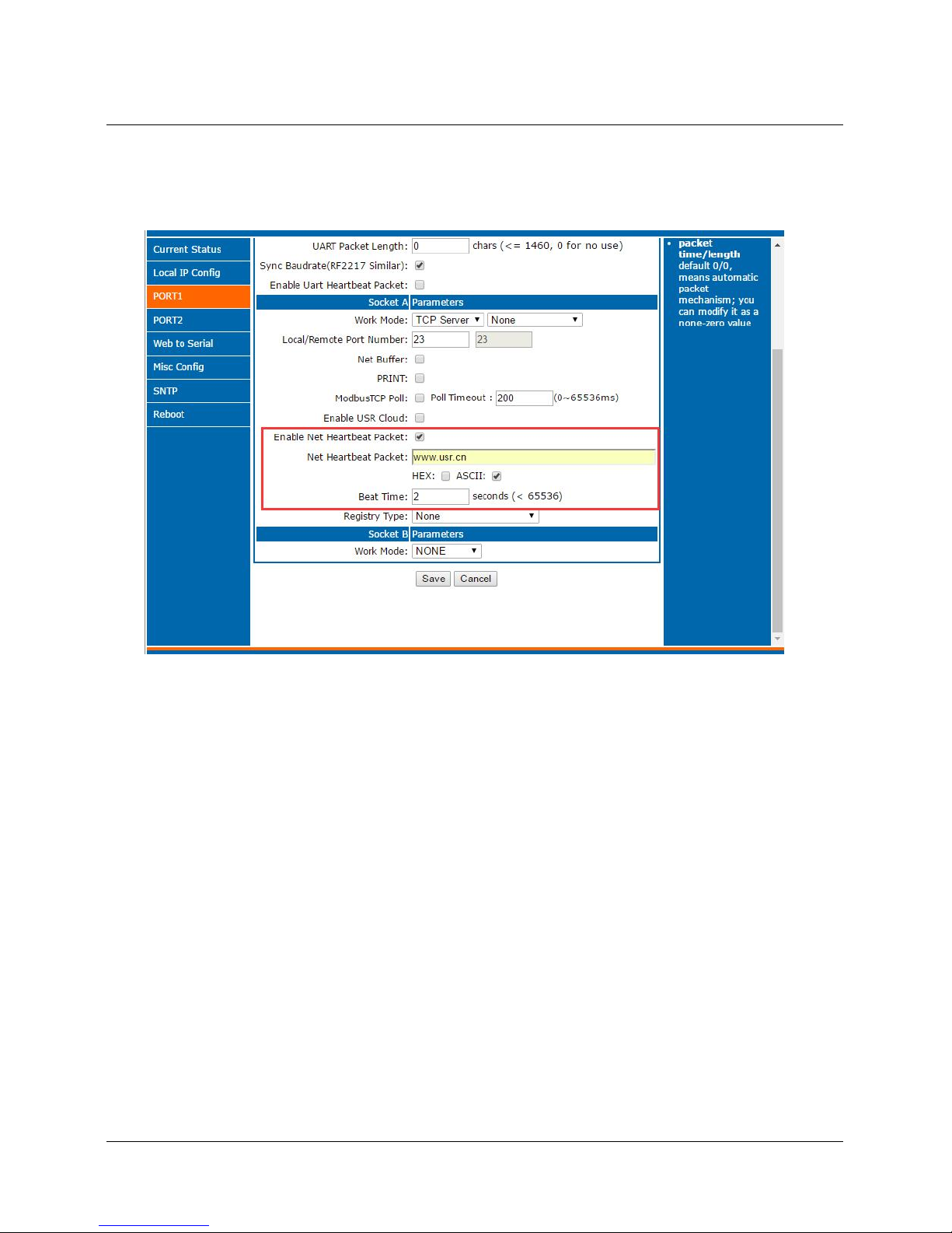
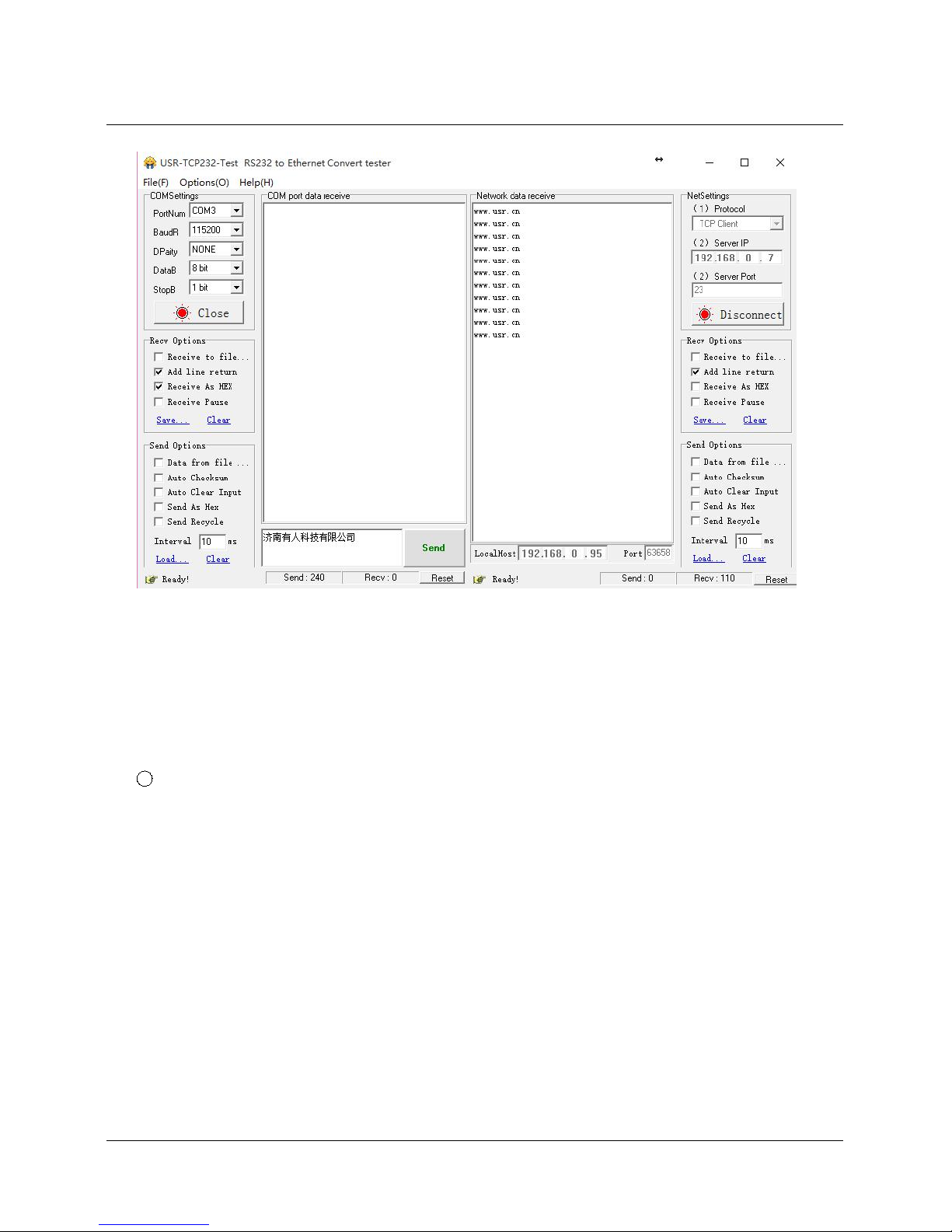
3.5.3. Self-Defined Heartbeat Function
USR-N520 supports heartbeat function. Heartbeat is divided into network heartbeat and serial port
heartbeat.
1 Set Network heartbeat through web page
Page 33
33 / 69
Drawing 26 - Self-Defined Heartbeat Function
Page 34
34 / 69
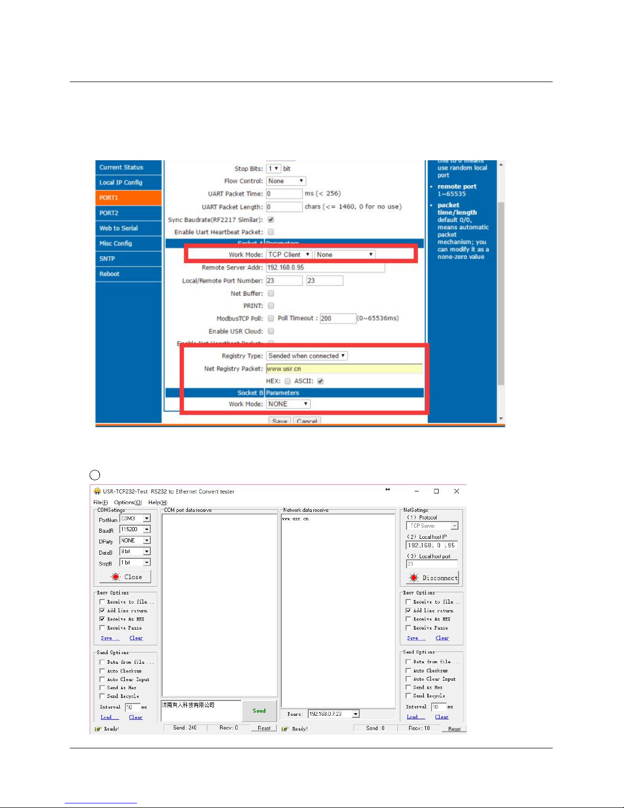
3.5.4. Self-Defined Registration Package Function
USR-N520 supports self-defined registration package function and also supports to send self-defined
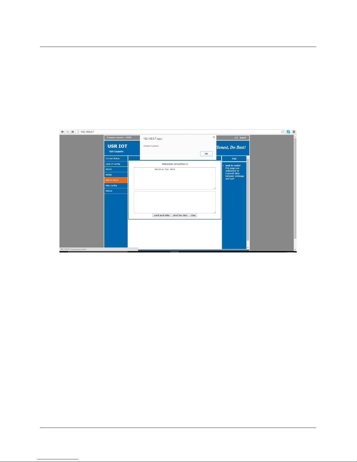
registration package after connection establishment, meanwhile, it supports to send registration package
when sending data. One example as blow:
1 Configure the relevant parameters via web page
Page 35
35 / 69
2 Testing result:
Page 36
36 / 69
3.5.5. Web to serial
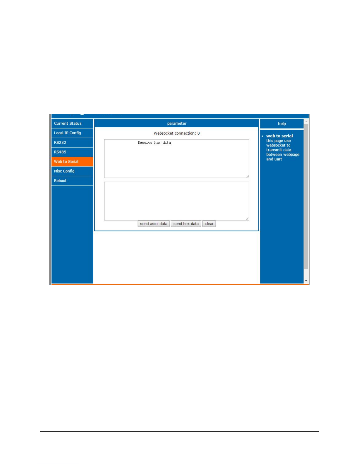
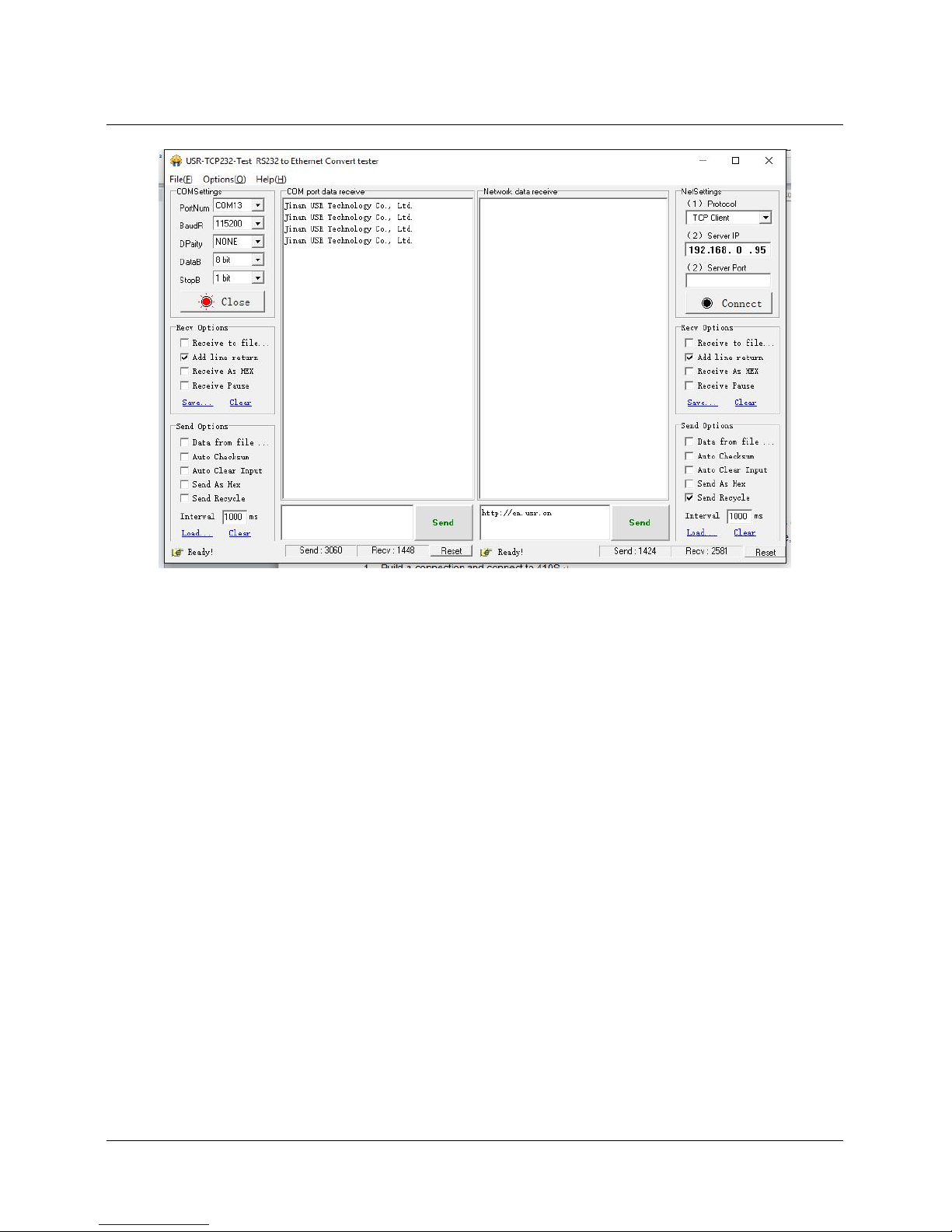
Web to serial function can make interaction between webpage and serial.
1. Set port 6432 as default.
2. Open webpage and click “web to serial”. It pops up “connect success” then can send/receive
data. Open USR-TCP232-TEST Software, configure serial parameter and click “Open”.
3. Click “send ASCII data”, COM can receive data. Click “Send” in TEST Software, webpage can
receive data.
Web to Serial Webpage
Page 37
37 / 69
Web to Serial COM Send/Receive Data
Page 38
38 / 69
Web to serial test
Web to serial needs user’s webpage programming ability. Design webpage, request own device’s data
and process data then reveal the results on webpage. According to chapter4.1.17 Customized Webpage, can
download revised webpage into USR-N520 .
1. Build a connection and connect to USR-N520
function connectx(){
try{
socket=new WebSocket('ws://'+window.location.host+':6432');
socket.binaryType = "arraybuffer";
}catch(e){
alert('error');
return;
}
socket.onopen = sOpen;
socket.onerror=sError;
socket.onmessage=sMessage;
socket.onclose=sClose
}
2. Receive Data Function
function sMessage(msg)
3. Send data function
function send()
Page 39
39 / 69
3.5.6. Customized Webpage
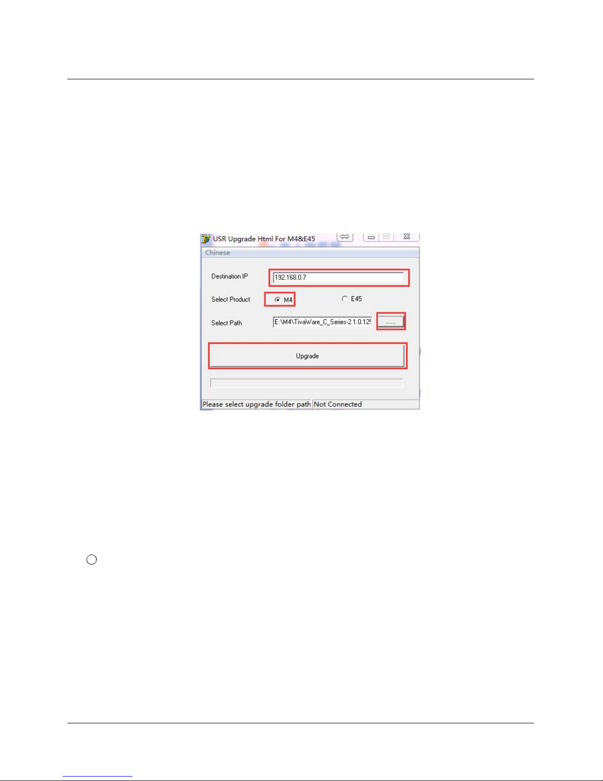
User can make revision as LOGO/NAME on the basis of USR-N520’s webpage to realize the
personalized applications.
1. Download Upgrade
2. http://www.usriot.com/e45-m4-seriesk3-self-defined-webpage/
3. Revise webpage code
4. Open “UpgradeHtml.exe”, set USR_N520’ IP, Select product M4 and upload revised webpage file.
Then upgrade.
Customized Webpage Upgrade
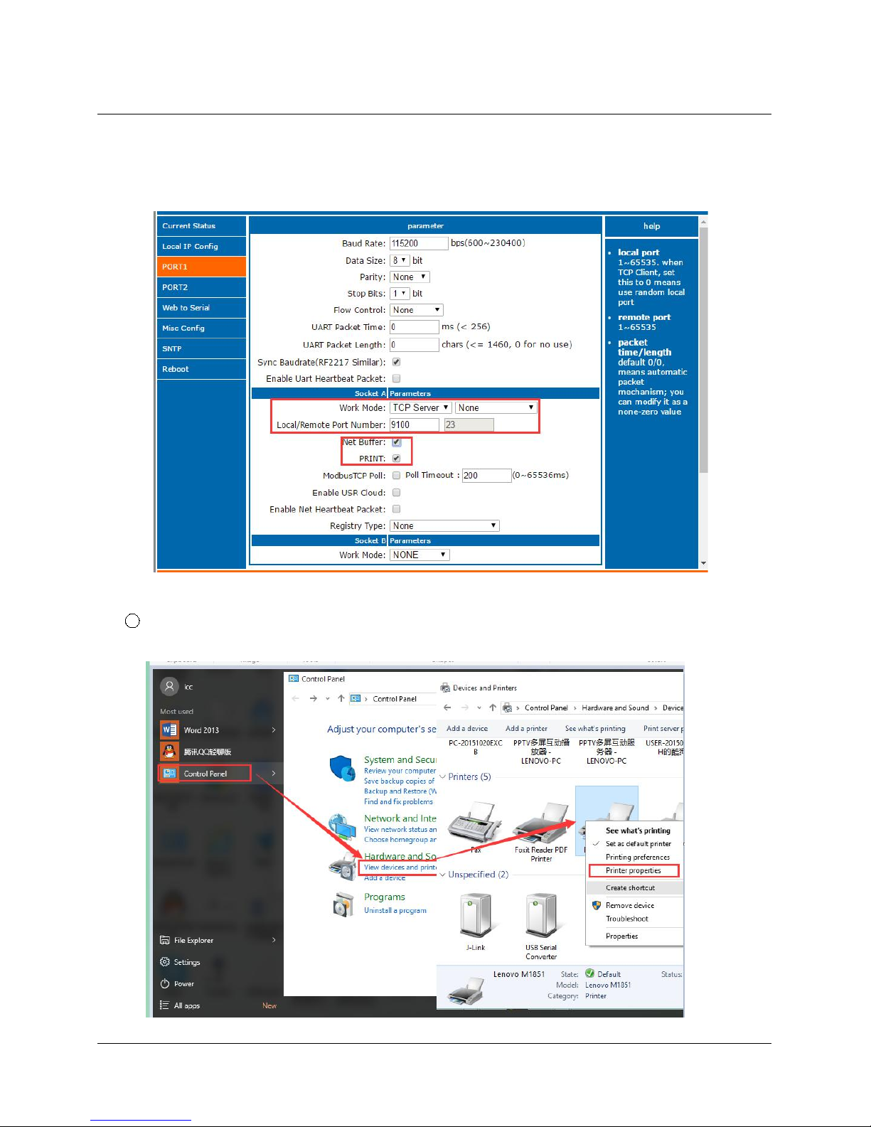
3.5.7. Network Printing Function
Network printing function is similar to printer server, it can be realized by the previous serial printer through
the existed printing driver.
Testing Method:
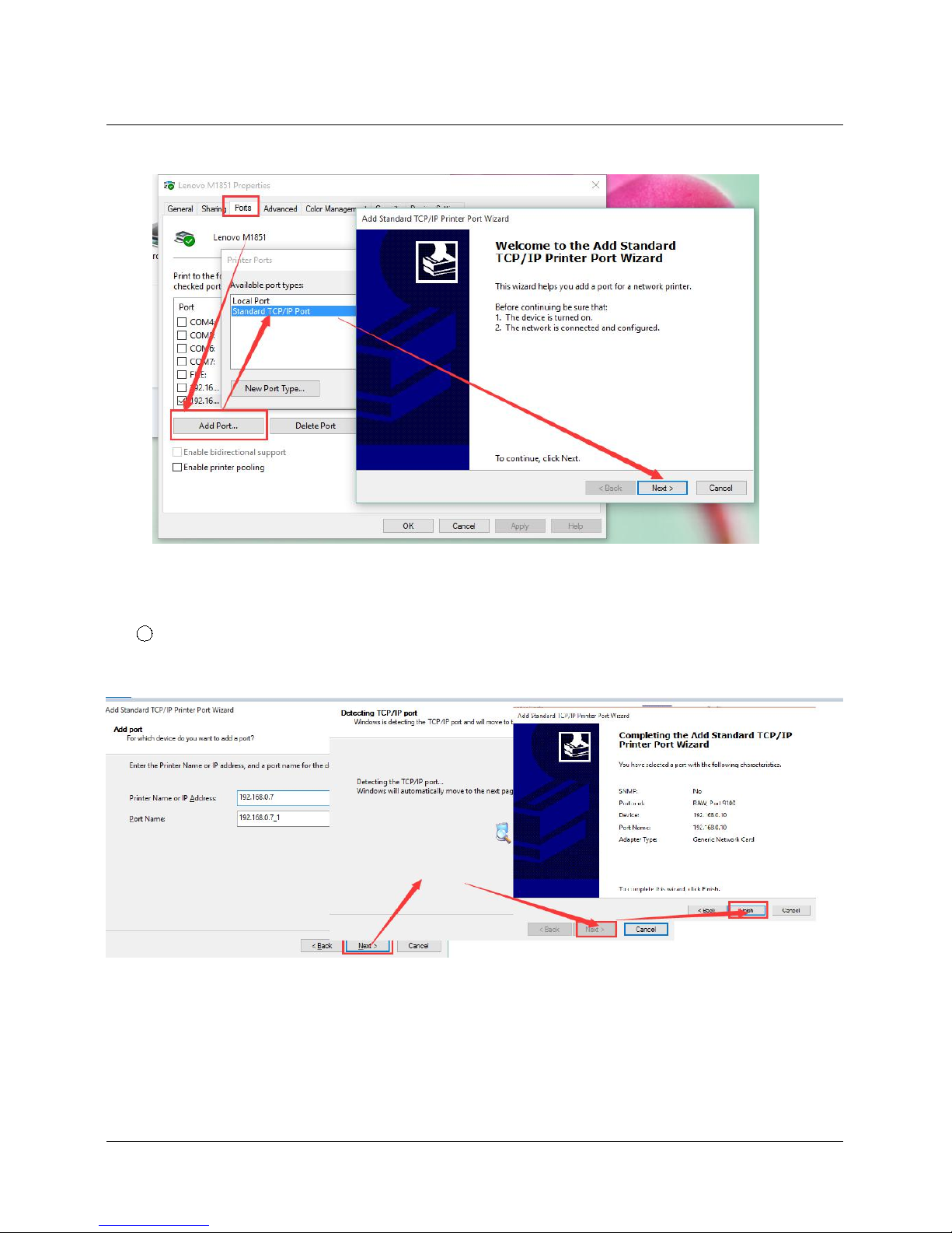
1 Configure the parameter, set work mode as “TCP Server”, local port number “9100”, and have to
choose “Net Buffer” and “PRINT”. Others do not need to be chosen.
Page 40
40 / 69
2 Set Printer Driver
Page 41
41 / 69
Click next and input the USR-N520’IP address,then keep clicking next til finished
3 Serial port connects to the printer, open a word file to print
3.5.8. Serial Port Packaging Mechanism
USR-N520 can configure serial port packaging time and serial port packaging length. USR-N520 will make
packaging for the data of serial port according to the packaging length and packaging time in the transparent
Page 42

42 / 69
transmission mode.
Example for judgment of packaging time and packaging length:
1 Set packaging time as 10ms, packaing length as 512 bytes
When serial port received data, USR-N520 will package and send it to network if the interval time of
receiving data is over than 10ms or data length is more than 512。
2 If the value of packaging time or packaging length is 0, the packaging rule is effective for non-zero
one.
3 Set packaging time and length as 0. USR-N520 will conduct default packaging time when
packaging time is set as 0ms. Namely, when serial port receiving data, USR-N520 will package and send the
data to network if interval time more than packaging time of sending 4 bytes. For example, baud rate 115200,
packaging time for 4 bytes is T=0.4ms, when the calculated value is smaller than 0.1ms, packaging time can
be calculated as 0.1ms.
T= 1/baud rate*10*4
3.5.9. Flow Calculation
When USR-N520 receives data from network and then send to serial port, as the limit of serial port speed,
user have to control the flow, if not the problem of data overflow on serial port side will occur. So data flow is
required to calculated when sending data from network to serial port.
Example:
Network sends data in m bytes every n seconds. Method of checking if there is overflow: ( Supposed
network condition is good and network data transmission time is negligible)
1 If there is no overflow, m bytes data must be transmitted within n seconds, then the transmitting time
of M bytes data:
If n >2T, then data will not overflow, USR-N520 can work normally. Just need keep n>T under baud rate
9600.
3.5.10. Synchronous baud rate (RFC2217)
For encryption during data transmission, devices change data bytes, baud rate, parity and so on.
USR-N520 supports revise serial parameter accordingly.
Page 43
43 / 69
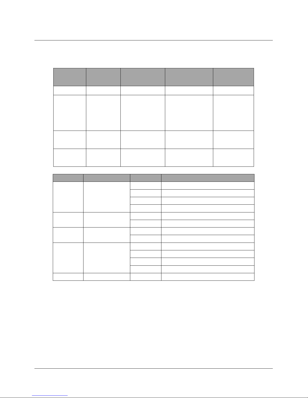
Synchronous baud rate is named RFC2217. USR Similar RFC2217 make adjustments on the basis of
RFC2217 protocol to improve accuracy of transmission.
Protocol length is 8 bytes. And values taken for example is in HEX:
Name
Packet
Header
Baud Rate
Bytes parameter
Parity
Bytes3311
Explanation
reduce
misjudgment
High is in front,
smallest is
600(00 02 58)
data bytes, baud
rate, parity
Remove 4 bits
of header and
ignore the high
bit
(115200,
N,8,1)
55 AA 55
01 C2 00
03
46
(9600,
N,8,1)
55 AA 55
00 25 80
03
28
Serial parameter bit:
Bit #
Explanation
Value
Description
1:0
Data bit selection
00
5 bits
01
6 bits
10
7 bits
11
8bits
2
Stop Bit
00
1 bit
01
2bits
3
Parity Enable
00
Disable Parity
01
Enable Parity
5:4
Parity Type
00
ODD
01
EVEN
10
Mark
11
Clear
8:6NC000
0
Using methods:
1. USR-TCP232-M4,E45 Setup software, click “Synchronous baud rate (RFC2217)”.
2. When serial parameter changes is needed, it send RFC 2217 packet. USR-N520 receive the
command from network and revise serial parameter accordingly.
Page 44

44 / 69
3.5.11. KeepAlive
When USR-N520’s network is abnormal, it can judge the status in time and disconnect. And connect to
server once network recovers.
3.5.12. Device ID
The function have 2 types: send ID once connection and send ID once sending data. It is used to
condition that need register packet or need packet header/tail for normal transmission.
3.5.13. Webpage Port
USR-N520 has built-in webpage server and the port is 80. Also the port can be revised and visit the web
via revised port.
3.5.14. Revise MAC
User can check software’s MAC address. USR-N520 MAC is Globally Unique. Also it support customized
MAC.
3.5.15. Firmware Upgrade
Firmware upgrade is fulfilled via network. For details, please refer to Chapter 5.1 configure parameter with
configuration software.
3.5.16. Hardware Flow Control RTS/CTS & XON/XoFF
RTS/CTS: USR-N520 supports serial RTS/CTS Hardware flow control function. It is disabled by default.
Don’t enable it if device doesn't support Hardware flow control . This function is only run under RS232 port.
XoN/XoFF: USR-N520 support software flow control function. It is disabled by default. It can be selected
under RS232 port or RS422 port.
3.5.17. Reload
Cut off power firstly.
Press “reload” and supply power. Then keep pressing reload for 5 seconds.
Page 45
45 / 69
Reload
4. Setting Protocol
USR-N520 includes two protocol: network setting protocol and serial port setting protocol.
4.1. Network Setting Protocol
4.1.1. Set Parameter Process
1. Build SOCKET:
Build UDP SOCKET, destination IP: 55.255.255.255, destination port: 1901. Low is in front.
2. Setting command process:
1 The network send searching command
2 USR-N520 returns IP address and MAC
3 The network read USR-N520’s parameter
4 Organize setting command according to MAC, known user name/password and parameter to be
configured.
5 Send setting command
6 USR-N520 returns “correct setting”
7 Host PC send “save setting” command
8 USR-N520 returns “correct”
9 Restart command
10 USE-N520 returns “correct setting”
4.1.2. Setting Command Content
Command Look-up List:
Function
Header
Length
command
MAC
(6 bytes)
User name
/password
(12bytes)
Parameter
Parity
(sum)
Page 46

46 / 69
search
FF0101---02
reset
FFxx02
[MAC]
[usrname]
[password]
-
xx
read
settings
FFxx03
[MAC]
[usrname]
[password]
-
xx
Save
settings
FFxx04
[MAC]
[usrname]
[password]
-
xx
Basic
settings
FFxx05
[MAC]
[usrname]
[password]
Basic
parameter
xx
Com 0
settings
FFxx06
[MAC]
[usrname]
[password]
COM
parameter
xx
Com 1
settings
FFxx07
[MAC]
[usrname]
[password]
COM
parameter
xx
Com 2
settings
FFxx08
[MAC]
[usrname]
[password]
COM
parameter
xx
USR
Cloud
0x10
[MAC]
[usrname]
[password]
Notice: Check bit is sum check, starts from length byte (including length) to adding before checking (not
including checking), result is check value, only low byte is remained.
1. Command examples
1 Search command example
Search command is set to:
FF 01 01 02
Sum check: 02 = 01 + 01
2 Reset command example
FF 13 02 d8 b0 4c 00 04 c9 61 64 6d 69 6e 00 61 64 6d 69 6e 00 c8
Sum check:
C8 = 13 + 02 + ... + 6E + 00
User name and password both are 5 bytes+00 bits 0 for the lack.
3 Read settings command example
Send (16 bytes):FF 13 03 AC CF 23 66 66 67 61 64 6D 69 6E 00 61 64 6D 69 6E 00 F9
4 Save reading settings command example
Send (16 bytes):FF 13 04 AC CF 23 66 66 67 61 64 6D 69 6E 00 61 64 6D 69 6E 00 FA
2. Some commands detailed annotation
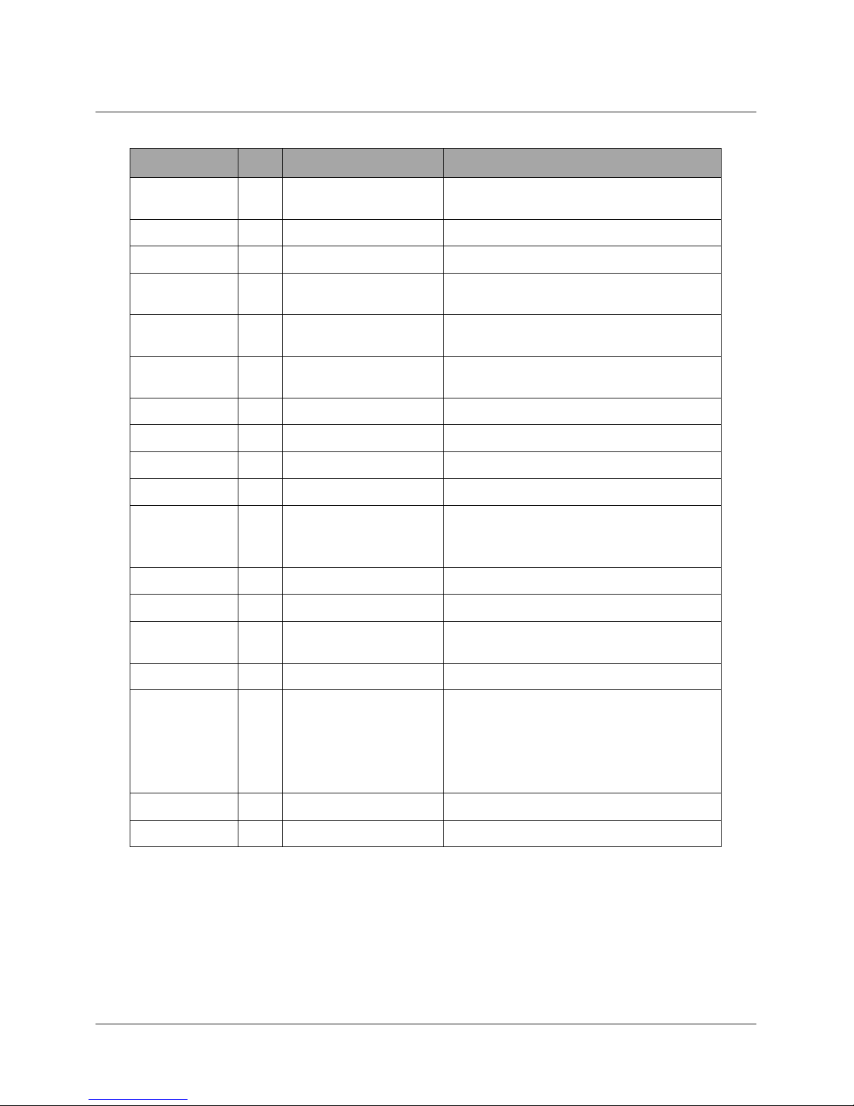
1 Basic setting parameter command
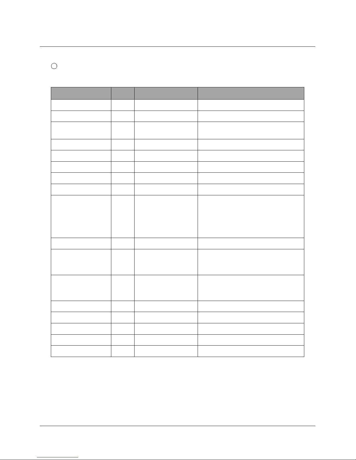
Page 47
47 / 69
Basic Parameter:
Name
Byte
Example
Explanation
ucSequenceN
um
1xxWrite the read values
ucCRC
1xxWrite the read values
ucVersion
1xxWrite the read values
ucFlags
180IP address type:
0 in 8thbit: DHCP;1 in 8thbit: Static IP
usLocationUR
LPort
2
20 19
Write the read values
usHTTPServer
Port
2
50 00
HTTP server port
ucUserFlag
1
Write the read values
ulStaticIP
4
38 00 A8 C0
Static IP
ulGatewayIP
4
01 00 A8 C0
Gateway
ulSubnetMask
4
00 FF FF FF
Subnet Mask
ucModName
16
55 53 52 2D 54 43 50
32 33 32 2D 45 00 00
00 00
USR-N520 name
username
6
61 64 6D 69 6E 00
username
password
6
61 64 6D 69 6E 00
password
ucNetSendTim
e
1
Write the read values
uiId201 00
Device ID
ucIdType
1
0
Device ID type (0~3)
0:no use
1:send id when connect
2:send id when send data
3:both
ucUserMAC
6
FF FF FF FF FF FF
MAC
ucReserved
8
Unused
Example:
FF 56 05 AC CF 23 66 66 67 61 64 6D 69 6E 00 61 64 6D 69 6E 00 61 66 03 80 20 19 50 00 02 07 00 A8 C0
01 00 A8 C0 00 FF FF FF 55 53 52 2D 54 43 50 32 33 32 2D 45 34 35 00 00 61 64 6D 69 6E 00 61 64 6D 69
6E 00 02 01 00 00 AC CF 23 66 66 67 00 48 54 54 50 2F 31 2E 1C
Page 48
48 / 69
2 Port settings parameter command
Port parameter:
Name
bytes
example
Explanation
ulBaudRate
4
00 C2 01 00
Baud Rate
ucDataSize
108COM data bits (0X05/0x06/0x07/0x08)
ucParity
1
01
COM parity
1: no, 2: odd, 3: even, 4: mark, 5: space
ucStopBits
101COM stop bit (0x01/0x02)
ucFlowControl
101COM flow control ( 0x01; no, 0x03:HW)
ulTelnetTimeout
4
00 00 00 00
Network reconnection time
usTelnetLocalPort
2
17 00
Local Port
usTelnetRemotePort
2
17 00
Remote Port
uiTelnetURL
30
31 39 32 2E 31 36 38
2E 30 2E 31 00 00 00
00 00 00 00 00 00 00
00 00 00 00 00 00 00
00 00
IP address send in ASCII.
Example: 192.168.0.1
ulTelnetIPAddr
4
00 00 00 00
Not adopted
ucFlags
1
02
Enable MODBUSTCP:0x010(bit2)
Enable 2217: 0x08(bit3)
Enable USR cloud: 0x010(bit4)
ucWorkMode
1
03
Working mode:
0: UDP, 1: TCP Client, 2: UDP Server,
3: TCP Server, 4: HTTPD Client
uiPackLen
4
C8 00 00 00
COM pack length
ucPackTime
10ACOM pack time
ucTimeCount
191Write the read values
TCP server type
11Write the read values
ucReserved
4
Casual value
saved
Example:
FF 52 06 AC CF 23 66 66 67 61 64 6D 69 6E 00 61 64 6D 69 6E 00 00 C2 01 00 08 01 01 01 00 00 00 00
17 00 17 00 31 39 32 2E 31 36 38 2E 30 2E 32 30 31 00 00 00 00 00 00 00 00 00 00 00 00 00 00 00 00 00 00
00 00 00 08 03 C8 00 00 00 0A 95 11 00 00 00 00 42
Page 49

49 / 69
4.1.3. Commands’ Return Content
1. Return results of search command
Return command:
Bytes
Name
Example
Explanation
0
TAG_STATUS
FF
1
Packet_length
24
2
CMD_DISCOVER_TARG
ET
01
3
Board_type
00
4
Board_ID
00
5~8
Client_IP_address
C0 A8 00 07
Device IP(High in front)
9~14
MAC_address
AC CF 23 20 FE
3D
Device MAC(High in front)
15~18
Firemware_version
D0 07 12 34
D0 07: device version# (low in
front)
12 34: encrypted version
19~34
Application_title
55 53 52 2D 54 43
50 32 33 32 2D 35
30 30 00 00
Device name
35
checksum
F0
checksum
Example:
Return results of search command(36 bytes)
FF 24 01 00 4B C0 A8 00 4D D8 B0 4C 00 04 C9 DD 07 01 00 55 53 52 2D 54 43 50 32 33 32 2D 34 30
31 00 00 EF
The method of the check is as follow:
0xEF = 00 - FF - 24 - 01 - 00 - 4B - ... - 31 - 00 - 00
2. Return results of reset command
Response(4 bytes): FF 01 02 4B, if user name and password are right, 4B = 'K'
FF 01 02 45, if user name and password are wrong, 45 = 'E'
3. Return results of read command
Description:
Return all parameter of USR-N520 network. 193 bytes in total, no parity, no protocol, return parameter
directly.
Page 50

50 / 69
Returned content: 193 (basic parameter+serial parameter+serial parameter)
4. Return results of save settings command
If settings are correct, it returns:
FF 01 04 4B
5. Return results of basic settings command
FF 01 05 4B
6. Others return results
Sum check fault returns 'E' + right parity
Correct execution: FF 01 CMD 'K'
User name/password fault returns: FF 01 CMD 'P'
Others faults return: FF 01 CMD 'E'
4.2. Serial Setting Protocol
4.2.1. AT Command
AT Command List:
Table 1 AT Command List
Command
Instruction
(blank)
Blank Command
E
Open/close echo function
Z
Re-start device
VER
Query version number
ENTM
Enter to transparent transmission mode
MAC
Query/set MAC
UART
Set/query serial port parameter
SOCKMN
Set SOCK parameter
DHCPEN
Open/close automatic obtaining IP address
WANN
Open/close WAN port parameter
WEBU
Query/set web page user’s name and password
WEBPOR
T
Query/set web page port number
SEARCH
Query/set searching key words
CLEAR
Factory reset
UART
Set/query serial port 0 parameter
Page 51

51 / 69
UART1
Set/query serial port 1 parameter
SOCK
Set/query port 0 network SOCKETA parameter
SOCK1
Set/query port 1 network SOCKETA parameter
SOCKB
Set/query port 0 network SOCKETB parameter
SOCKB1
Set/query port 1 network SOCKETB parameter
MAC
Query MAC parameter
WRMAC
Set MAC parameter
DNS
Set/query domain name analyzing address
WANN
Set/query module IP address, gateway, subnet mask
parameter
Page 52

52 / 69
4.2.2. Enter AT Command Mode
1 Send +++ to USR-N520 through serial port
2 USR-N520 return ‘a’
3 Need reply “a” within 3s once received previous ‘a’
4 Return+ok to enter AT command mode
4.2.3. AT Command details
1. AT+E
Function: Set/query echo setting
Format:
Query
AT+E <CR>
<CR><LF>+OK=<on/off><CR><LF>
Set
AT+E=<on/off><CR>
<CR><LF>+OK<CR><LF>
Parameter:
1 on: Open echo function, and input AT command (Echo on)
2 off: Close echo function. (Echo off)
2. AT+ENTM
Function: Enter transparent transmission mode (Exit command mode)
Format:
Set
AT+ENTM<CR>
<CR><LF>+OK<CR><LF>
Parameter: N/M
Change work mode from command mode to transparent transmission mode after run this
command correctly
3. AT+Z
Function: Re-start USR-N520
Format:
Set
AT+Z<CR>
<CR><LF>+OK<CR><LF>
Parameter: N/M
<Notice>: USR-N520 will re-start after run this command correctly.
Date xxxx.xx.xx (For example 2014.01.02 stands for January 2nd, 2014).
Page 53

53 / 69
4. AT+VERFunction: Set/query firmware version
Format:Query
AT+VER<CR>
<CR><LF>+OK=<ver><CR><LF>
Parameter:
ver: Set/Query the firmware version of USR-N520
Gerenal version: AA.BB.CC: AA stands for big version, BB stands for small version
number, CC stands for hardware version C.C
Custom version: AA.BB.CC.DD-ID; DD stands for customer’s version, ID stands for
customer’s ID number
5. AT+MACFunction: Query MAC
Format:Query
AT+MAC<CR>
<CR><LF>+OK=<mac><CR><LF>
Parameter:
mac: MAC Address of USR-N520 (Example 01020304050A);
6. AT+WRMACFunction: Set MAC
Format:Set
AT+WRMAC=<mac><CR>
<CR><LF>+OK<CR><LF>
Parameter:
mac: MAC Address of USR-N520 (Example 01020304050A);
7. AT+WEBUFunction: Set/query user’s name and password of web page
Format:Query
AT+WEBU<CR>
<CR><LF>+OK=<username,password><CR><LF>
Set
AT+WEBU<CR>
<CR><LF>+OK =<username,password><CR><LF>
Parameter:
username: user’s name, supports max 5 bytes. Does not support blank
password: password, supports max 5 bytes
Page 54

54 / 69
8. AT+WEBPORT
Function: Set/query web server port of USR-N520
Format:Query
AT+WEBPORT<CR>
<CR><LF>+OK=<port><CR><LF>
Set
AT+WEBPORT<CR>
<CR><LF>+OK =<port><CR><LF>
Parameter:
port: web server’s port of USR-N520, default 80;
9. AT+SEARCH
Function: Set/query search port and key words of USR-N520 inside LAN
Format:Query
AT+SEARCH<CR>
<CR><LF>+OK=<port,keywords><CR><LF>
Set
AT+ SEARCH <CR>
<CR><LF>+OK =< port,keywords><CR><LF>
Parameter:
port: serching port of USR-N520, default 48899
keywords: searching key words of USR-N520, Default: www.usr.cn (Max 20 bytes).
9. AT+CLEARFunction: Restore factory setting
Format:Set
AT+CLEAR<CR>
<CR><LF>+OK<CR><LF>
Parameter: N/M
10. AT+UARTFunction: Set/query the parameter of UART0
Format:Query:
AT+UART<CR>
<CR><LF>+OK=<baudrate,data_bits,stop_bit,parity,flowctrl,uartnum><CR><LF>
Set
AT+UART=<baudrate,data_bits,stop_bit,parity,flowctrl,uartnum ><CR><LF>
<CR><LF>+OK<CR><LF>
Parameter:
baudrate: baud rate
9600,19200,38400,57600,115200,230400,380400,460800
Page 55

55 / 69
data_bits: data bits 5,6,7,8
stop_bits: stop bits 1,1.5,2 (which module supports)
parity: check bit
NONE (no check bit)
EVEN (even check)
ODD (odd check)
MASK (1 check)
SPACE (0 check)
flowctrl: hardware flow control (CTS RTS)
NFC: no hardware flow control
FC: hardware flow control
485: supports 485, after opening, RS_EN pin and RTS pin are the same
uartnum:0
11. AT+UART1Function: Set/query UART0 interface parameter
12. AT+SOCKMN
(M: socket number, A~H. N: corresponding serial port number, 1~8. Omit MN numbers for single serial
port and single socket)
Function: Set/query network protocol parameter format:
Query
AT+SOCKMN<CR>
<CR><LF>+OK=<protocol,IP,port ><CR><LF>
Set
AT+SOCKMN=< protocol,IP,port ><CR>
<CR><LF>+OK<CR><LF>
Parameter:
Protocol: protocol type
TCPS: TCP server
TCPC: TCP client
UDPS: UDP server
UDPC: UDP client
TCPA: TCP auto
WEBUART: websocket, tranmission from webpage to serial port
IP: Server’s IP address when USR-N520 works as “CLIENT’
Port: Protocol port, decimal number, smaller than 65535
13. AT+DHCPENFunction: Open/close DHCP Server;
Format:Query
AT+DHCPEN<CR>
<CR><LF>+OK=<Type><CR><LF>
Page 56

56 / 69
Set
AT+DHCPGW=<Type><CR>
<CR><LF>+OK<CR><LF>
Parameter
Type:On: open DHCP server function
Off: close DHCP server function (USR-N520 works as wireless switch at this time)
14. AT+WANNFunction: Set/query obtained WAN port IP (DHCP/STATIC);
Format:Query
AT+WANN<CR>
<CR><LF>+OK=<mode,address,mask,gateway><CR><LF>
Set
AT+WANN=<mode,address,mask,gateway><CR>
<CR><LF>+OK<CR><LF>
Parameter:
mode: network IP mode.
static: static IP
DHCP: dynamic IP (address, mask, gateway parameter is omitted)
address: IP address.
mask: subnet mask.
gateway: gateway address.
5. Parameter Configuration
It is setup software configuration, webpage configuration and serial configuration.
How to configure:
Revise user name/password→set IP access method→serial parameter→USR-N520 work mode→work
mode related parameter
5.1. Software Configuration
To make sure setup software normal running, please check the below firstly:
1. USR-N520 and setup software PC are within same LAN.
2. Disable the anti-virus software and firewall on PC.
3. Disable network card nothing to do with this testing.
Download [USR-TCP232-M4&E45] Setup software here:
http://www.usriot.com/usr-tcp232-m4e45-setup-v2-3-0-78/
Page 57
57 / 69
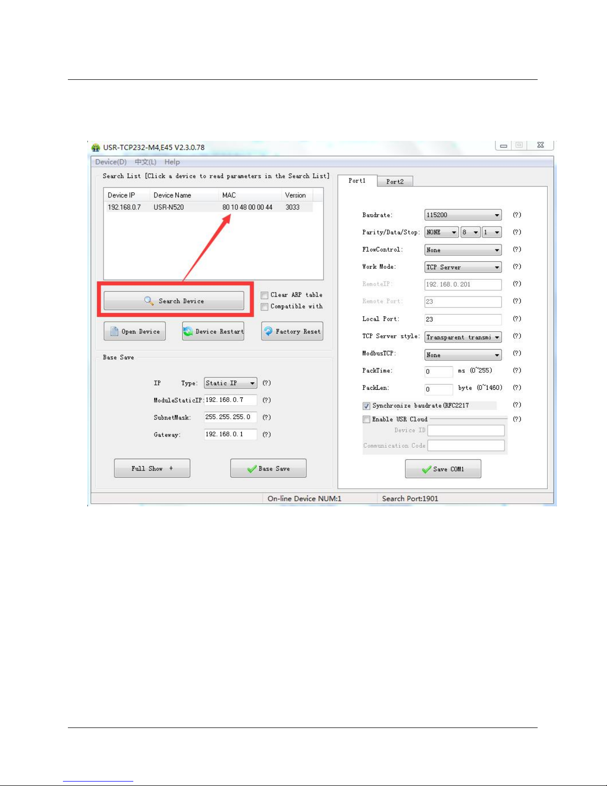
Search device and all USR-N520 device within LAN can be found. It includes IP, name, MAC and
version.
Software Configuration—Search
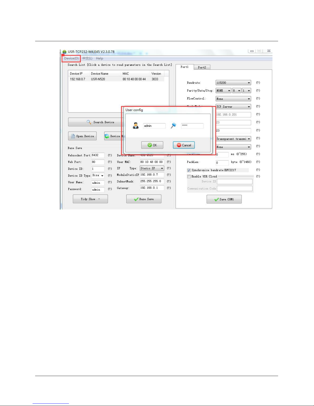
1. Click ‘Device’ on the top of the program and then check user name/password via ‘User config’. If it is
correct, it reveals USR-N520 information. If not, it pops up retype window, click “Confirm”.
User name and password is admin by default.
Page 58
58 / 69
Software Configuration-Password
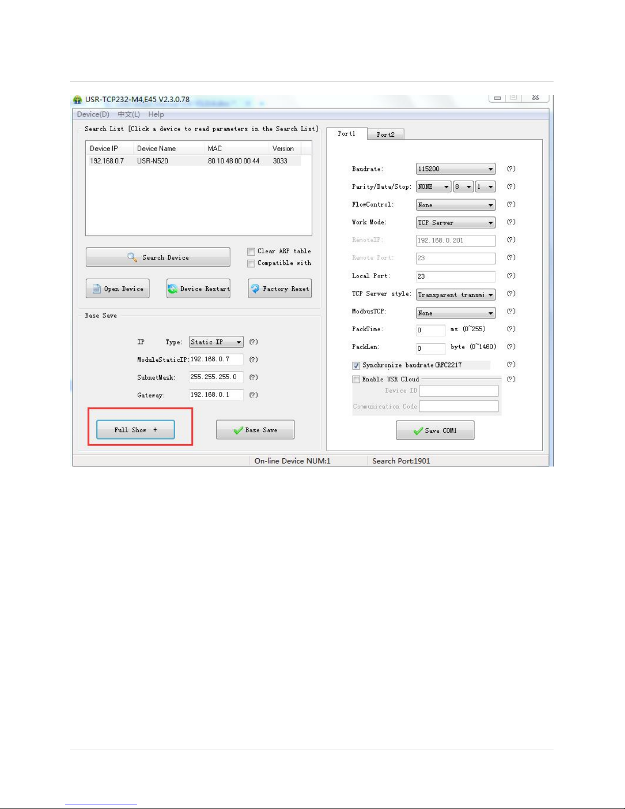
2. Basic parameter configuration
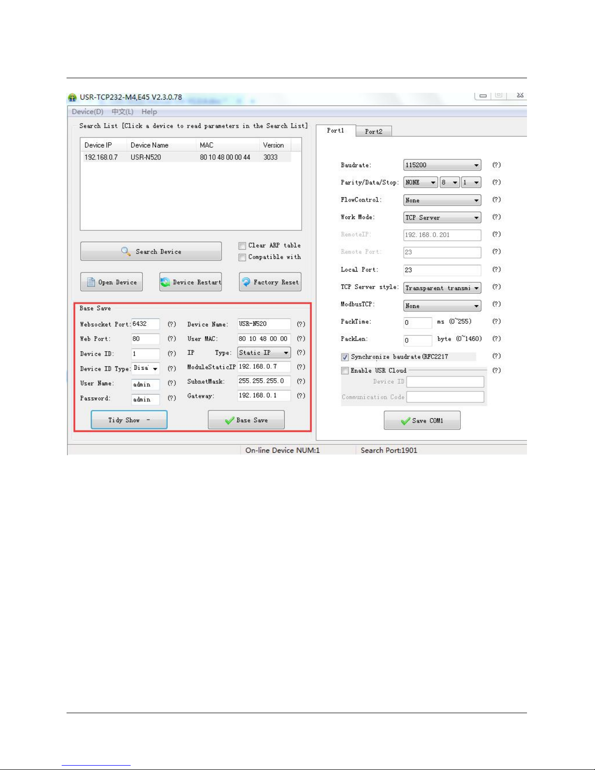
Click “Full Show” and all basic parameter is revealed.
Set the parameter as needs and click “Base Save” then can set successfully.
Page 59
59 / 69
Software Configuration --Full Show
Page 60
60 / 69
Software Configuration-Base Save
Websocket port: refer to Chapter 4.1.8.3 Webpage to serial
Webpage port: it is 80 by default when visit webpage.
Device ID: refer to Chapter 4.1.8.6 Device ID
Device ID type: sending ID type
User name: Authentication Code for revising parameter to avoid other users within same LAN
revising it.
Password: same as user name.
Device Name: USR-N520 ’s name an be revised.
MAC address: USR-N520 ’ MAC
IP address type: Static and DHCP
USR-N520 static IP: same segment with router.
Subnet Mask: 255.255.255.0 by default.
Gateway: it is router IP generally, can transmit cross network segment and DNS if set correctly.
Page 61
61 / 69
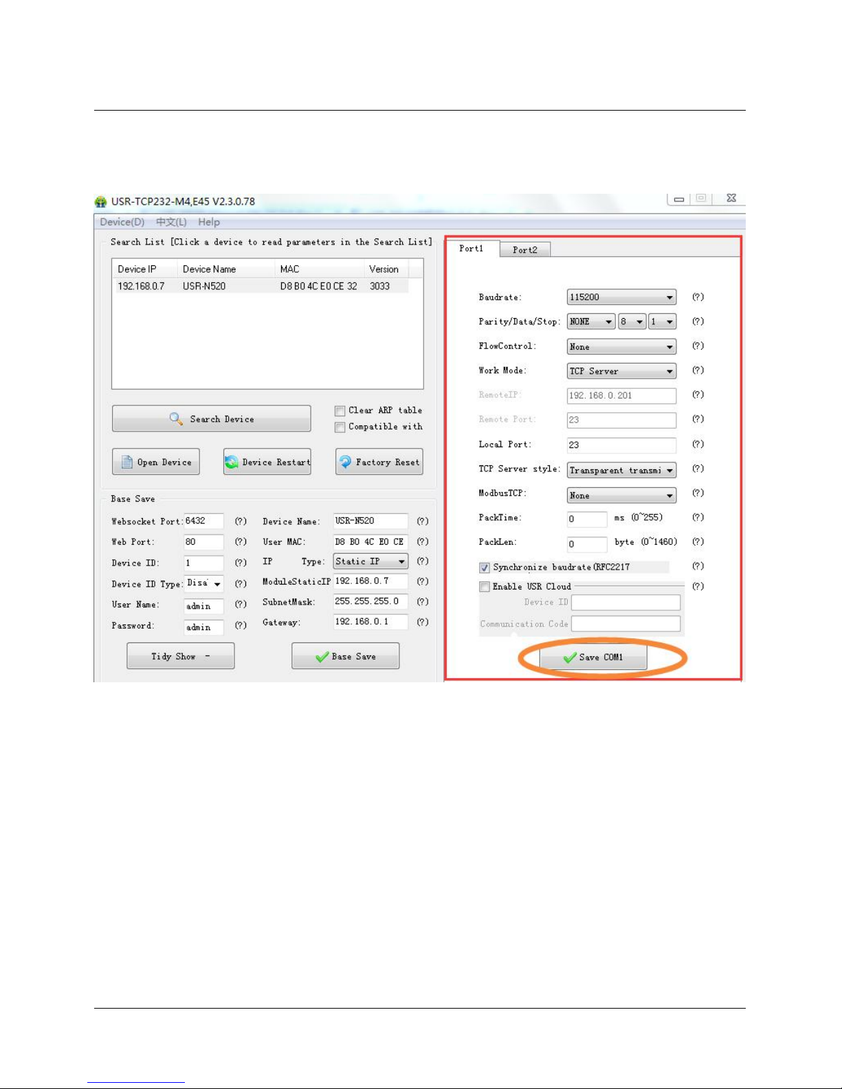
3. Port configuration ( Port1 / Port2 configuration)
Click the COM to set, revise parameter then click “Save COM1”.
Software Configuration-COM 1 Configuration
Serial Baud rate: it can be standard or customized.
Parity/Data/Stop: serial parameter.
Serial Flow control: None/Hardware/XON XOFF, None for no flow control, Hardware for hardware flow
control, XON/XOFF for software hardware flow.
Work Mode: TCP Server /TCP Client/HTTPD Client/UDP Client/UDP Server
Destination IP/Port: IP connected when USR-N520 works as client (TCP Client/HTTPD Client/UDP
Client)
Local Port: port USR-N520 to connect. Advice to set it to “0’’ when USR-N520 works under TCP
Client for connection with Random port.
TCP Server Type: No.
Modbus TCP: set this when Modbus TCP to Modbus RTU is needed.
Serial pack time: relate to serial unpacking mechanism.
Serial pack length: relate to serial unpacking mechanism.
Similar RFC2217: Please refer to Chapter 3.5.10 Similar RFC2217
Page 62
62 / 69
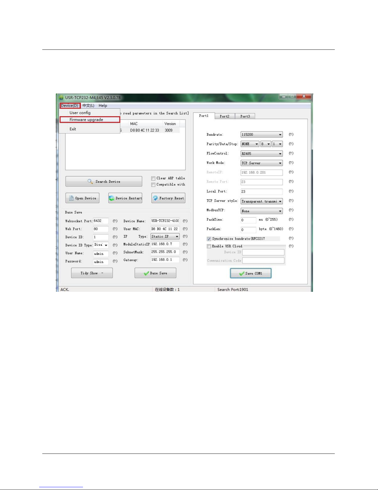
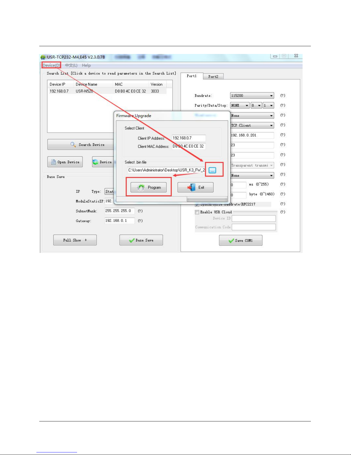
4. Firmware Upgrade
If USR-N520 need to upgrade with new firmware, please contact USR sales.
During firmware upgrade, USR-N520 connects to PC directly. PC Upgrade via Wi-Fi is prohibited.
Page 63
63 / 69
Firmware Upgrade
5.2. Webpage Configuration
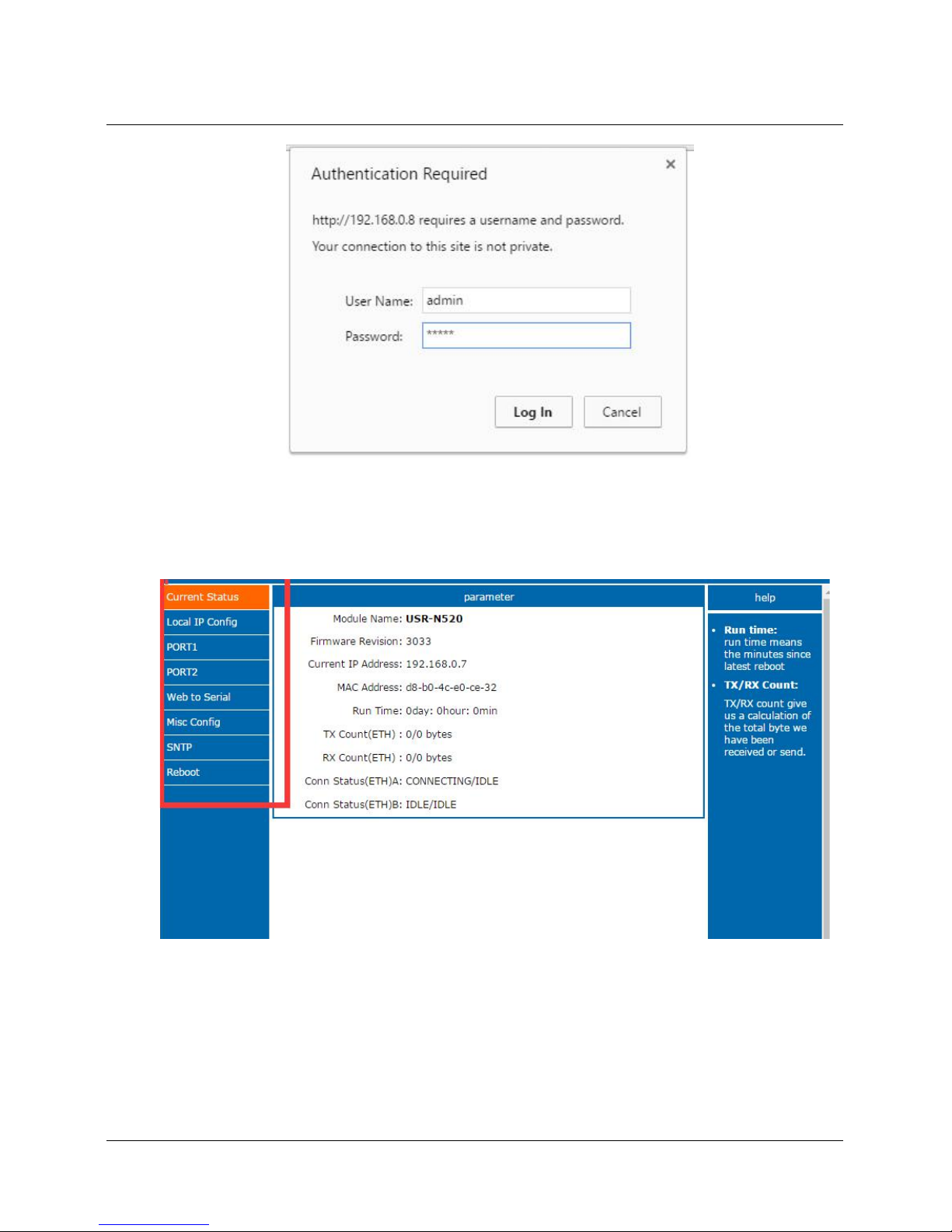
Open browser and type in USR-N520 ’ IP (192.168.0.7 by default)
Then user name: admin and password: admin.
Page 64
64 / 69
Webpage Log In
1. Current Status - reveals basic information:
USR-N520 name
Firmware version
Current IP address
MAC address
Total running time: from be powered
Count of data sending: how many data sent from powered
Page 65
65 / 69
Count of data receiving: how many data received from powered
USR-N520 connection status: check whether connection is built.
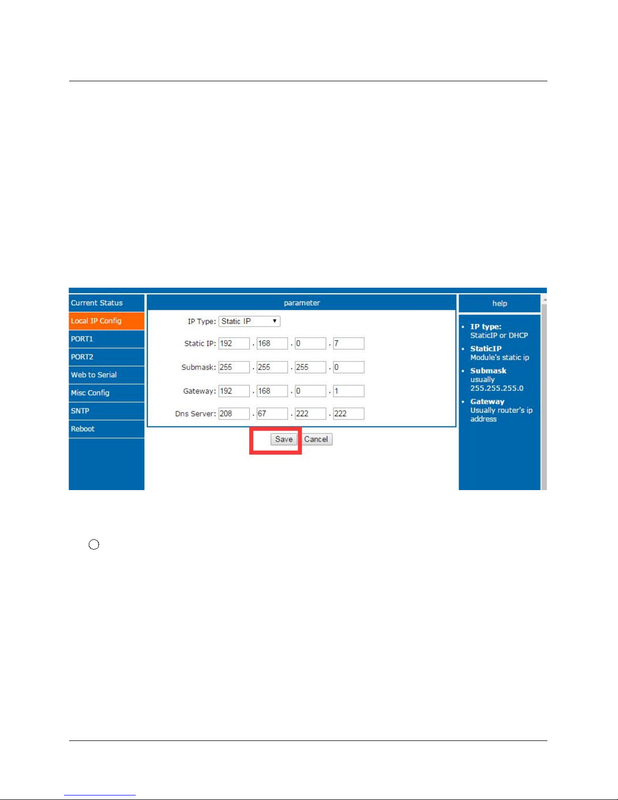
2. Local IP Config
Save configuration after revise. Then restart.
Local IP Configuration
IP address gaining methods
Local IP
Subnet Mask
Gateway
Webpage Configuration-Local IP Configuration
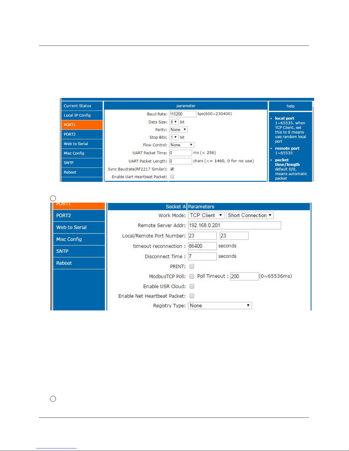
3. PORT1
1 Basic Parameter, as below
Baud Rate
Data Bit
Parity Bit
Stop Bit
Flow hardware and RS485
Local Port
Remote Port
Work Mode
Remote server address
Serial pack time
Serial pack length
Page 66
66 / 69
Similar RCF2217
2 Socket A Parameters Configuration
Work Mode
Remote Server Address
Local/Remote Port number
Timeout reconnection
Disonnect time
Print: Function for network printing
ModbusTCP Poll: Function for Modbus Polling
Enable Net Heartbeat Packet: user-defined heartbeat packet
Registry type: User-defined registration packet
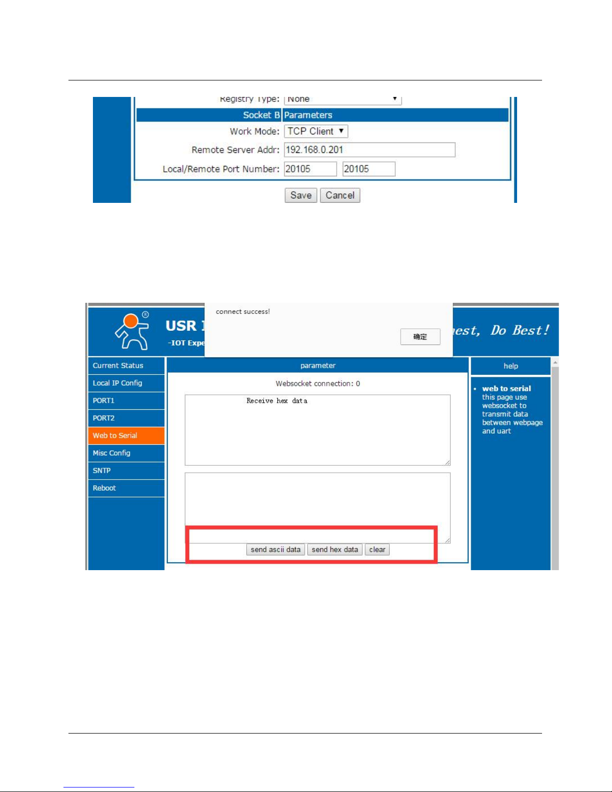
3 Socket B Parameters Configuration
Page 67
67 / 69
Work Mode: TCP Client/UDP Client
Remote Server Address
Local/Remote Port number
4. Web to serial
Click “web to serial ” and “connect success” pops up. Confirm then send data.
Web to Serial
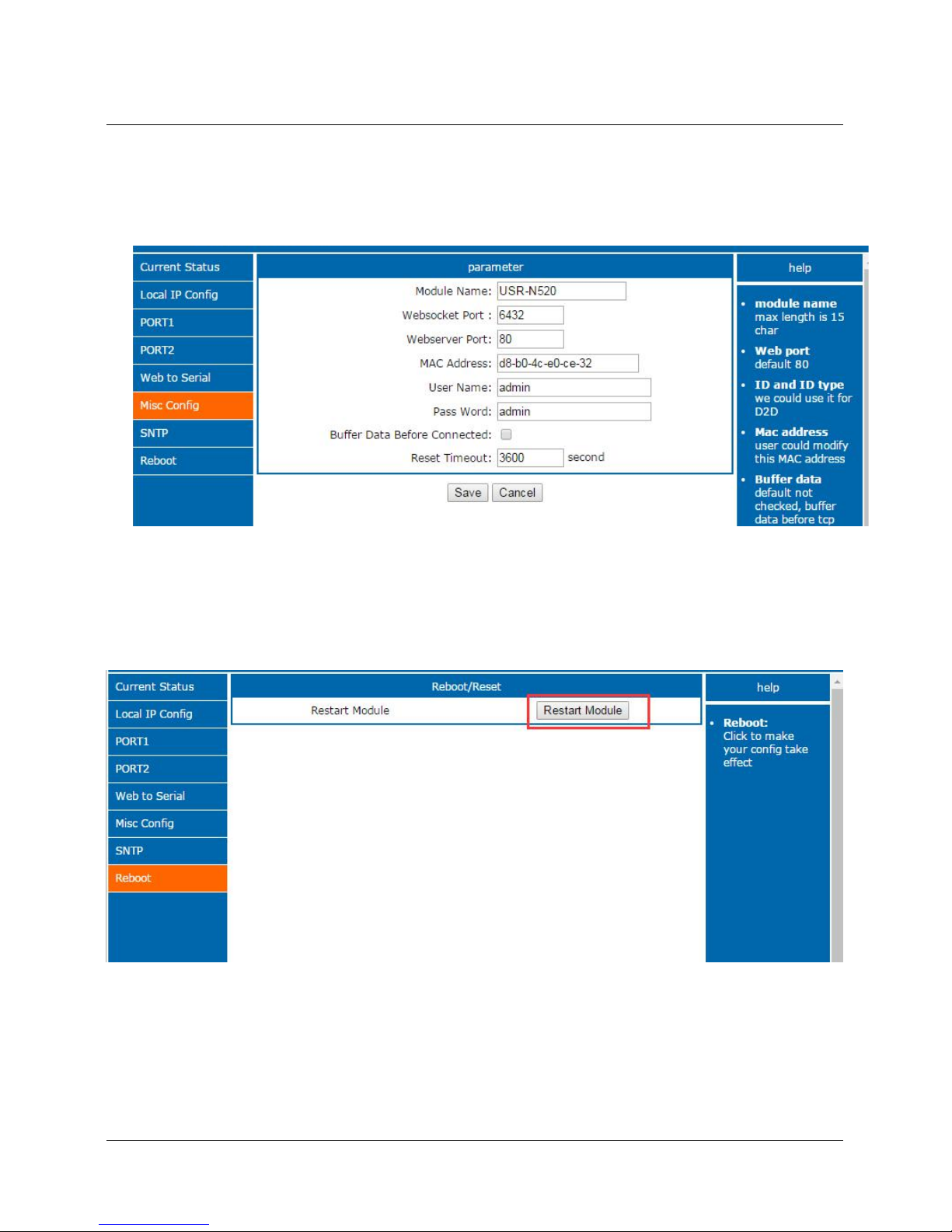
5. Misc Config (Advanced configuration)
Module Name: USR-N520 ( User can modify it)
Websocket Port
Webserver Port
User Name/ Password: For webpage, user can modify it
MAC Address (can be revised)
Buffer data before connected: whether serial and network data are cached if disconnection.
Reset timeout: how long USR-N520 reset when no data from COM or Network. Set to “0” then no
rest.
Page 68
68 / 69
6. Reboot
Save all data then click restart to take effect.
Webpage configuration- Restart
5.3 Serial Configuration
Serial configuration use AT command, please refer to Chapter 4.2 Serial setting Protocol.
Page 69

69 / 69
 Loading...