

Page 1
USR-K6 User Manual www.usriot.com
USR-K6 User Manual
File Version: V1.0.0
Jinan USR IOT Technology Limited 1 / 107 [email protected]
Page 2

USR-K6 User Manual www.usriot.com
Contents
1. Get Start ......................................................................................................................................................................... 5
1.1. Testing Environment ............................................................................................................................................ 6
1.1.1. Hardware Prepare ..................................................................................................................................... 6
1.1.2. Hardware Connection ............................................................................................................................... 8
1.2. Network Testing ................................................................................................................................................... 8
1.3. Default Parameters .............................................................................................................................................. 9
1.4. Data Transport Testing ....................................................................................................................................... 10
2. Overview ....................................................................................................................................................................... 11
2.1. Brief Introduction .............................................................................................................................................. 11
2.2. Function feature ................................................................................................................................................ 11
2.3. Basic Parameters................................................................................................................................................ 12
3. Hardware Parameters ................................................................................................................................................... 14
3.1. Pin Definition ..................................................................................................................................................... 14
3.2. Dimension .......................................................................................................................................................... 15
4. Product Function .......................................................................................................................................................... 16
4.1. Network Basic Functions ................................................................................................................................... 17
4.1.1. IP address/ subnet masks/ gateway ........................................................................................................ 17
4.1.2. DNS Server Address ................................................................................................................................ 19
4.1.3. Web Server ............................................................................................................................................. 20
4.1.4. Restore to the Factory Setting. ............................................................................................................... 21
4.1.5. Network Upgrade Firmware ................................................................................................................... 21
Jinan USR IOT Technology Limited 2 / 107 [email protected]
Page 3

USR-K6 User Manual www.usriot.com
4.2. Socket ................................................................................................................................................................ 21
4.2.1. TCP Client ................................................................................................................................................ 23
4.2.2. TCP Server ............................................................................................................................................... 27
4.2.3. UDP Client ............................................................................................................................................... 30
4.2.4. UDP Server .............................................................................................................................................. 33
4.2.5. HTTPD Client ........................................................................................................................................... 34
4.2.6. VCOM ..................................................................................................................................................... 37
4.3. Serial Port Function ........................................................................................................................................... 37
4.3.1. Basic Parameters ..................................................................................................................................... 38
4.3.2. Serial Port Framing.................................................................................................................................. 38
4.3.3. RFC2217 .................................................................................................................................................. 39
4.4. Special Function ................................................................................................................................................. 43
4.4.1. Heartbeat Package .................................................................................................................................. 43
4.4.2. Registration package ............................................................................................................................... 45
4.4.3. USR-cloud ............................................................................................................................................... 46
4.4.4. Customize webpage ................................................................................................................................ 49
4.4.5. Link ......................................................................................................................................................... 50
4.4.6. Reset ....................................................................................................................................................... 50
4.4.7. Index ....................................................................................................................................................... 50
4.4.8. The number of the connected client ...................................................................................................... 53
4.4.9. State ........................................................................................................................................................ 53
4.4.10. Short Connection .................................................................................................................................. 54
Jinan USR IOT Technology Limited 3 / 107 [email protected]
Page 4

USR-K6 User Manual www.usriot.com
4.4.11. Clear Buffer Data ................................................................................................................................... 55
4.4.12. Restart Timeout .................................................................................................................................... 56
5. Parameter Setting ......................................................................................................................................................... 57
5.1. Net Protocol Setting Parameters ........................................................................................................................ 57
5.1.1. Setting Software Setting Parameters ...................................................................................................... 58
5.1.2. Setting Protocol Setting the Parameters ................................................................................................. 62
5.2. Webpage Setting Parameters ............................................................................................................................ 74
5.3. AT Command ..................................................................................................................................................... 80
5.3.1. AT Command Overview........................................................................................................................... 80
5.3.2. AT Command Error Code ........................................................................................................................ 82
5.3.3. AT Command .......................................................................................................................................... 82
5.3.4. AT Command Details ............................................................................................................................... 85
6. Contact us ................................................................................................................................................................... 106
7. Disclaimer ................................................................................................................................................................... 106
8. Modified History ......................................................................................................................................................... 107
Jinan USR IOT Technology Limited 4 / 107 [email protected]
Page 5

USR-K6 User Manual www.usriot.com
1. Get Start
USR-K6 is a small module for serial port to Ethernet, which can realize the bi-directed data transparent
transmission between RJ45 port and TTL serial port. It can be applied to interface 232 and 485 by level conversion
circuit.
Product link: https://www.usriot.com/products/low-cost-solution-super-port-ethernet-module.html
Related software:
M0 setting software: https://www.usriot.com/support/downloads/usr-m0-setup-software-v224288.html (which can
be also used in the the low cost serial to ethernet converters such as USR-TCP232-302, USR-TCP232-304 and
USR-TCP232-306, and embedded ethernet modules USR-TCP232-T2,USR-TCP232-S2)
Testing software: https://www.usriot.com/support/downloads/usr-tcp-test-testing-software.html
(USR-TCP232-Test.exe)
Jinan USR IOT Technology Limited 5 / 107 [email protected]
Page 6
USR-K6 User Manual www.usriot.com
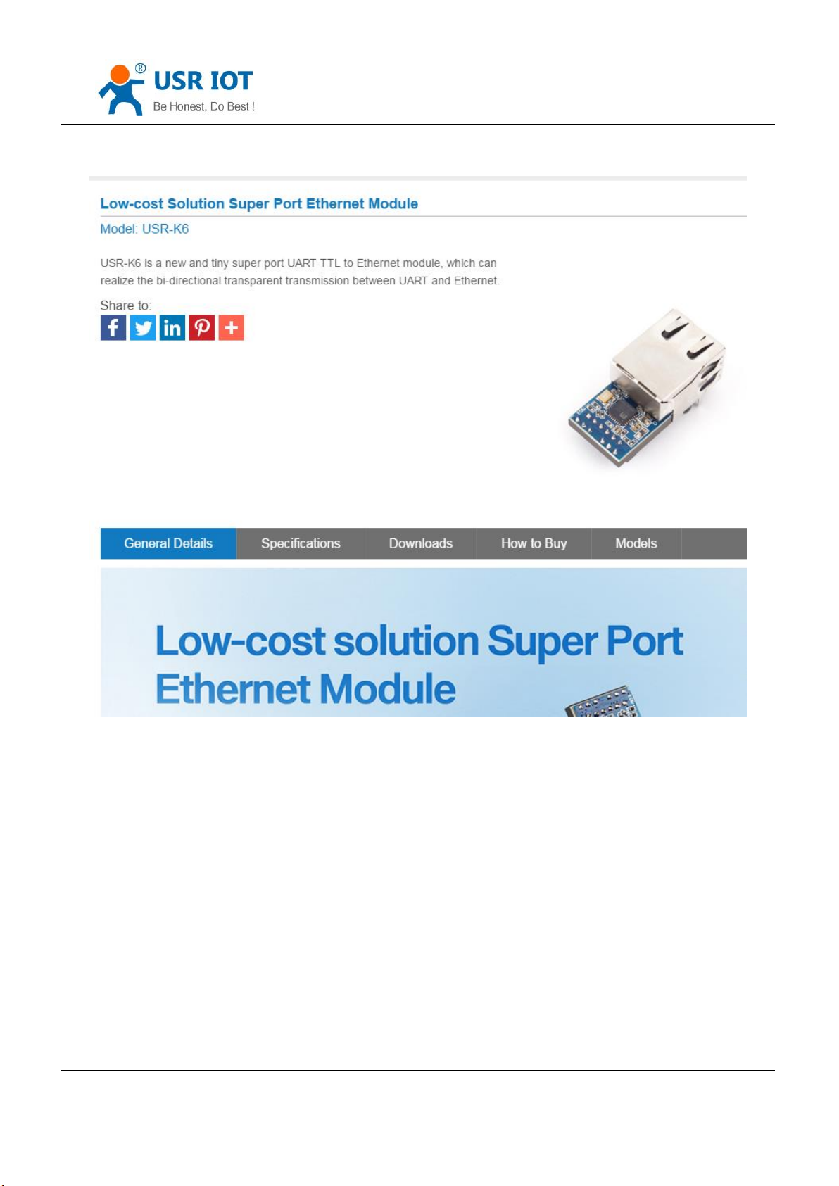
Diagram 1-1 Download Page
Some question in you using, please refer to the applications:http://www.usr.cn/Faq/cat-46.html
Also can be submit to our USR custom supporting: http://h.usriot.com
1.1. Testing Environment
1.1.1. Hardware Prepare
USR-K6*1
Jinan USR IOT Technology Limited 6 / 107 [email protected]
Page 7
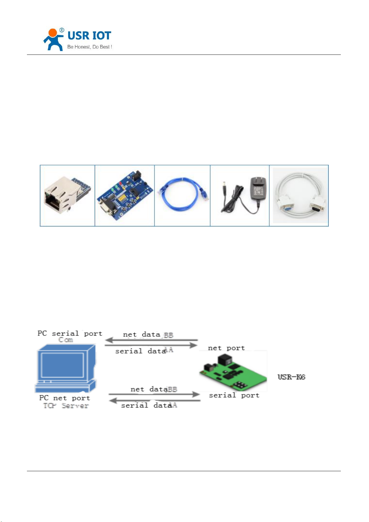
USR-Kx-EVK*1
Cable*1
Power (DC5V 1A)*1
Serial port cable *1
PC*1
USR-K6 User Manual www.usriot.com
Diagram 1.1.1-1 Testing Tools
1.Test purposes:
Test to realize the USR-K6, have a basic understanding of USR-K6
Test to know whether there are some thing wrong with it.
2.Data direction:
Diagram 1.1.1-2 Data Direction
Jinan USR IOT Technology Limited 7 / 107 [email protected]
Page 8
USR-K6 User Manual www.usriot.com
1.1.2. Hardware Connection
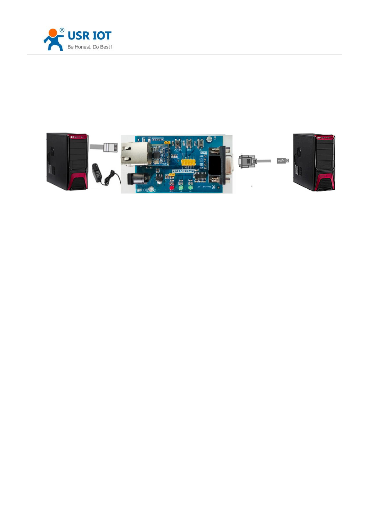
To test the conversion from serial port to ethernet, we put the serial port of K6 connected to PC via serial cable.
Connect the interface of the K6 and PC using net cable. After testing and found no mistake, powered for K6.
Diagram 1.1.2-1 Hardware Connection
Note: the power adapter and the cable are from USR
1.2. Network Testing
To prevent the thing that occurs when the custom use the K6 such as finding no server, can not ping and can not
enter the webpage, after connecting you should check the PC before testing.
1)Shut down firewall and antivirus software.
2)Shut down net card none-related and reserve only one local connection .
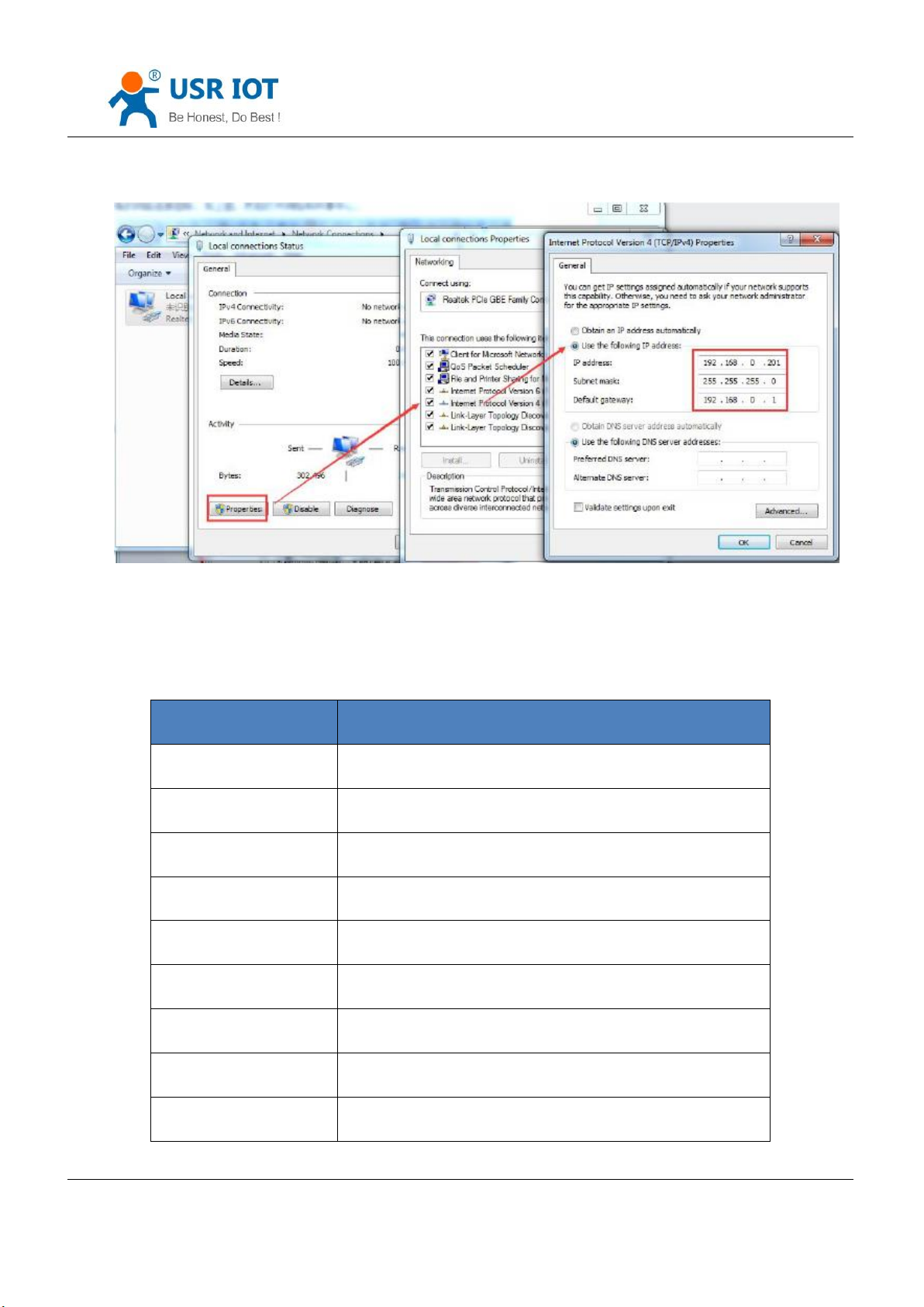
3)For the direct connection between PC and server, please provide a static IP in the same LAN with the IP of K6.
Jinan USR IOT Technology Limited 8 / 107 [email protected]
Page 9
USR-K6 User Manual www.usriot.com
Project
Intro
User name
admin
Key word
admin
IP address
192.168.0.7
Subnet masks
255.255.255.0
Default network gateway
192.168.0.1
Default work mode
TCP client
Default local port
0
Default target port
8234
Default local port
20108
1.3. Default Parameters
Diagram 1.2-1 Local Connection of the PC
Jinan USR IOT Technology Limited 9 / 107 [email protected]
Page 10
USR-K6 User Manual www.usriot.com
Default target IP
192.168.0.201
Serial port baud
115200
Serial parameter
None/8/1
Form 1.3-1 Default Parameters
1.4. Data Transport Testing
Then the serial port and ethernet can communicate bi-directly, steps are as fellows:
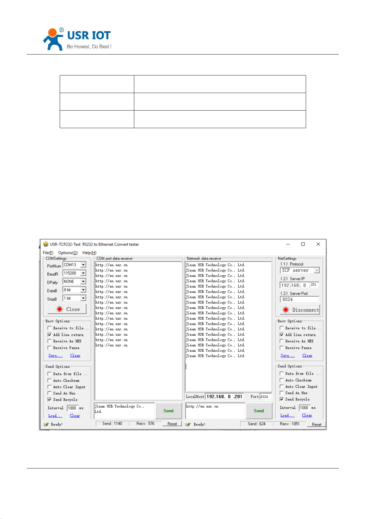
① Open the”USR-TCP232-Test.exe” and connect the hardware as the Diagram 1.1.2-1 Hardware Connection
② Select the TCP server mode in the “Net Setting” . Fill the PC IP into the server IP, server port 8324, click to start
listen and build TCP client. Baud rate:115200, serial parameters:None/8/1, then click to open the serial port.
Jinan USR IOT Technology Limited 10 / 107 [email protected]
Diagram 1.4-1 Default Parameters Testing
Page 11
USR-K6 User Manual www.usriot.com
2. Overview
2.1. Brief Introduction
USR-K6 is a tiny size serial port to Ethernet module which can realize the bi-direct data transparent transmission
between RJ45 port and TTL serial port. It can be applied to RS232 and RS485 by level conversion circuit.
Supports low power consumption, only consume a little current in full speed work. Equipped with Cortex-M0 core,
fast speed and high efficiency. Supports several functions to meet more need.
K6 is easy to operate and have strong compatibility. On the basis of adding new functions, it is compatible with the
setting protocol of K5, which provide convenience for old users. At the same time, a setting protocol similar to K3 is
added. For customers who adopt other series of products, it can be applied to K6 only by simple adjustment.
2.2. Function feature
adopted to Ethernet, supports AUTO-MDIX switching of network cable crossovers.
s:TCP server, TCP client, UDP server, UDP client, Httpd client, can be chose.
Parity including None, Odd, Eben, Mark, Space.
and keep the connection real and reliable, can be used to test the death
connection
Under TCP Server mode, the number of client connected can be modify from 1 to 16, default is 4. The IP of
connected client can be see. Send and receive data according to connection calculation.
Under TCP Server mode, when the client number reach the max number, the new client can instead of the old
one or not can be set.
AT command, serial port protocol, webpage setting parameter, setting protocol. Provide
custom to use in their own software.
Jinan USR IOT Technology Limited 11 / 107 [email protected]
Page 12
USR-K6 User Manual www.usriot.com
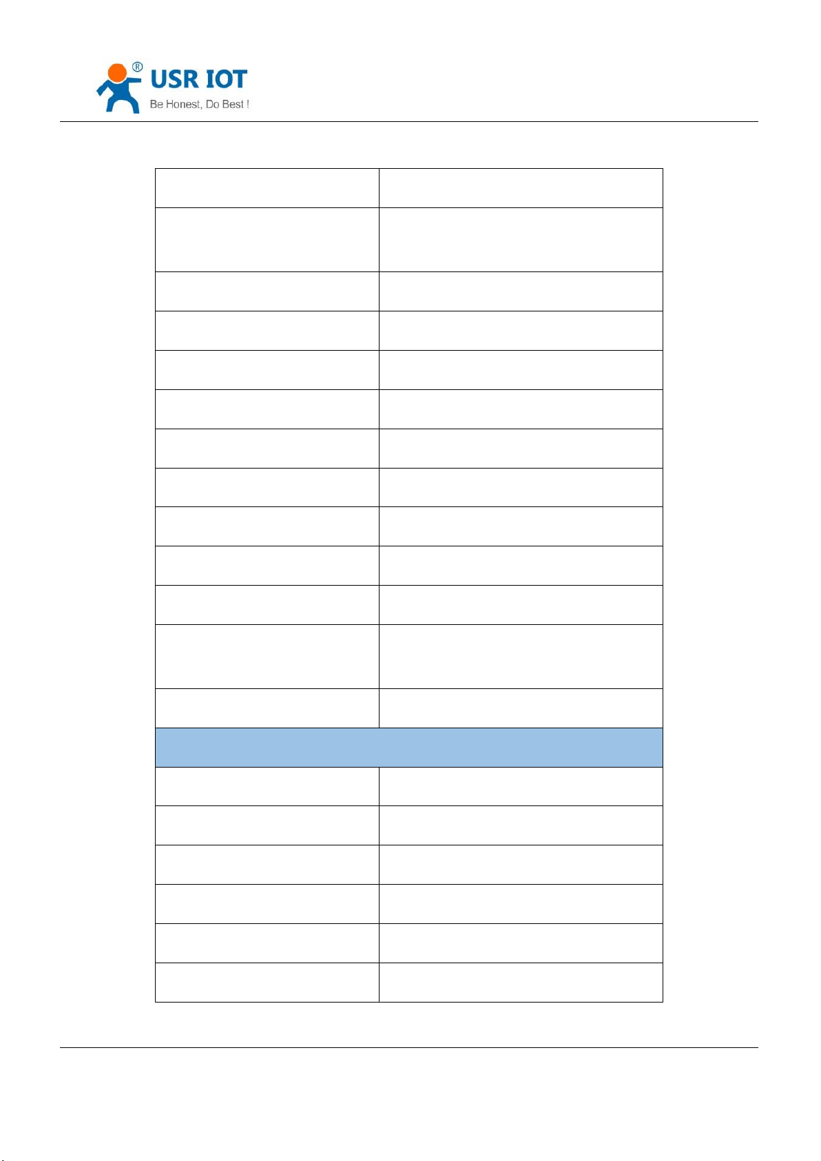
Parameter
Value
Input Voltage
DC3~3.6V
Working Current
Net port
Rj45, 10/100mMbps
Serial port
600~460.8K(bps)
Software parameters
Network protocol
IP, IPV4, TCP/UDP, ARP, ICMP
Access way to IP
Static IP, DHCP
restart out time, the time can be set.
ort DNS, domain name resolution.
V-com.
tore to the factory setting.
g and router.
2.3. Basic Parameters
Jinan USR IOT Technology Limited 12 / 107 [email protected]
Page 13
USR-K6 User Manual www.usriot.com
DDNS
Support
User parameters
Software setting, webpage setting, AT
command
Single transparent transmission
TCP Server/TCP client/UDP Server/UDP Client
Similar RFC2217
Support
Httpd client
support
TCP server connection
Default 4 and maximum 16
Net buffer
Send:6Kbyte; receive:4Kbyte
Serial port buffer
Receive: 2048byte
Average transport delay
<10ms
Set software
USR-VCOM, USR-Cloud, parameters setting
software
Package mechanism
4 byte package time and 1024byte length
others
Certification
CE,FCC
Size
35.0x19.39x18.25 mm(L*W*H)
Operating Temp.
-25~+75°C
Storage temp
-45~+105°C
operating humidity
5%~95% RH
Storage humidity
5%~95% RH
Jinan USR IOT Technology Limited 13 / 107 [email protected]
Page 14
USR-K6 User Manual www.usriot.com
Package
Electrostatic bubble
Num
Pin
Function
Instr
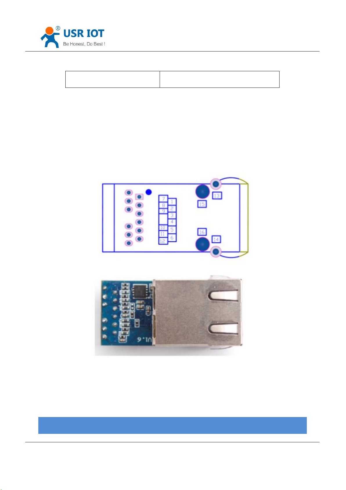
3. Hardware Parameters
3.1. Pin Definition
Form 2.3-1 Basic Parameters
Jinan USR IOT Technology Limited 14 / 107 [email protected]
Diagram 3.1-1 Pin
Page 15

USR-K6 User Manual www.usriot.com
1
N/C
N/C
N/C 2 N/C
N/C
N/C
3
Link
Connected status
of TCP
Used as indication pin for TCP connection status. If the LINK
function is enable and connected, this LED will light.
4
RST
reset
Connected to the IP of the user’s MCU, reset when abnormal,
reset when the pin reach 200ms
5
485-en
Reserve pin
RS485 enable pin
6
CFG
(reload)
Configuring the pin
using serial
When normal working , don’t connect the pin or connect to
high level. Under low level, the pin is used for module
configuration, access to power then pull down“Reload” pin
Refer to 4.4.3 Factory Reset
7
LED2
Net port data instr
Single chip data indicator foot, when data transport in the
network, it will flash.
8
RXD
Module data
receive
TTL connect to 3.3v MUC
9
TXD
Module data send
TTL connect to 3.3v MCU
10
GND
Signal location
Grounding
11
VCC
Power
Power:3.3V@200mA
12
NC \
Form 3.1-1 Pin Definition
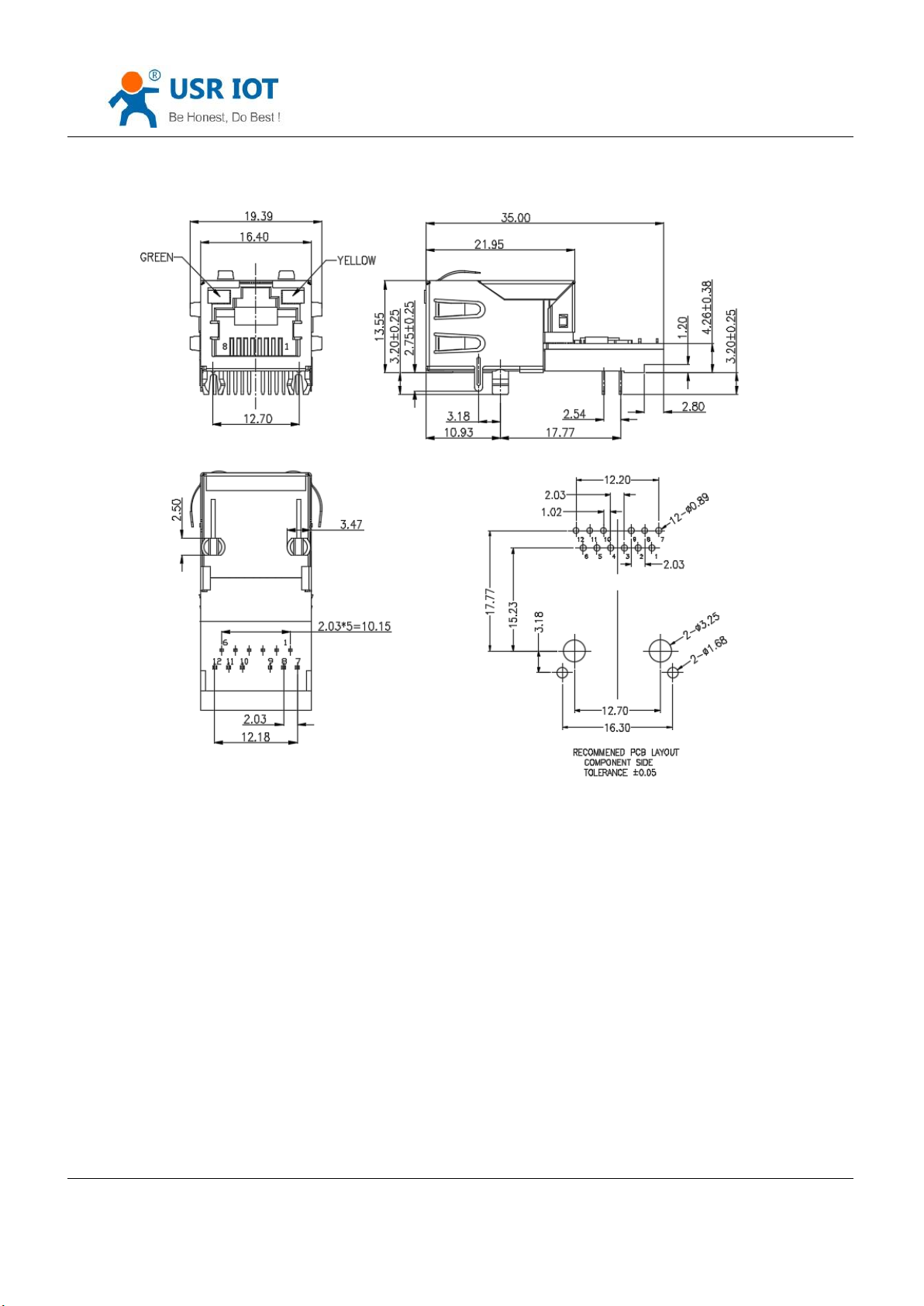
3.2. Dimension
Jinan USR IOT Technology Limited 15 / 107 [email protected]
Page 16
USR-K6 User Manual www.usriot.com
Diagram 3.2-1 Dimension
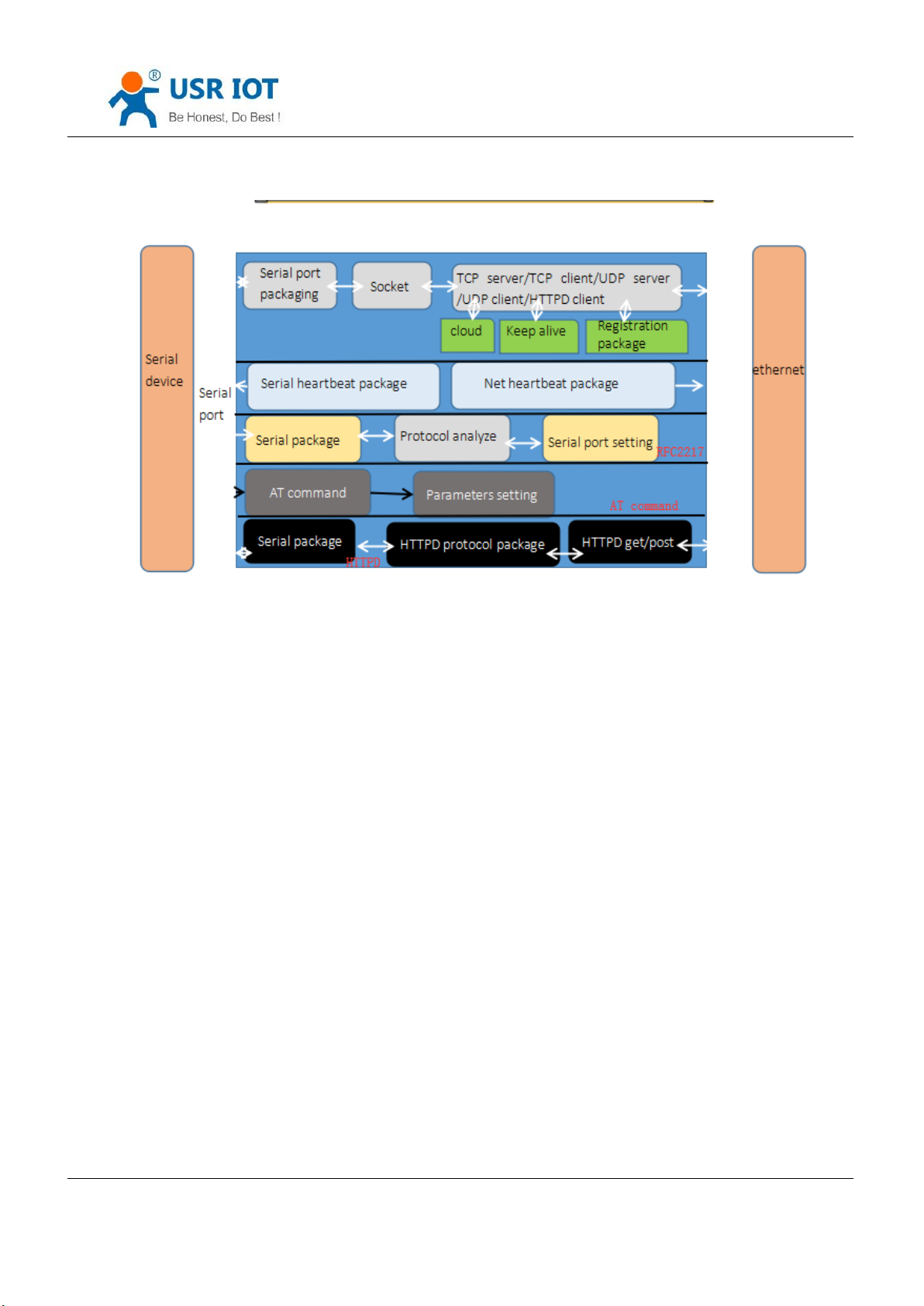
4. Product Function
Here are the functions of K6, below is the overall block diagram.
Jinan USR IOT Technology Limited 16 / 107 [email protected]
Page 17
USR-K6 User Manual www.usriot.com
Diagram 4-1functions
4.1. Network Basic Functions
4.1.1. IP address/ subnet masks/ gateway
1. IP address is the identity representation of the module in the LAN, which is unique in the LAN, so please be sure
there is no another device same as it in the LAN.
Static IP
Handle to setting. Note fill the IP, subnet masks and gateway.
Static IP adopted to the environment that required to statistics the IP and the device and makes them correspond
one to one.
Advantage: accessing the device that can not distribute IP address can be searched via UDP broadcast.
Disadvantage: different net segment in the different LAN can not communicate normally.
DHCP
Jinan USR IOT Technology Limited 17 / 107 [email protected]
Page 18
USR-K6 User Manual www.usriot.com
command name
instr
AT+WAN
Setting and query the access way of K6 IP, IP/subnet
masks/gateway parameters
Get IP address , gateway address, DNS server and other information from the gateway server to easy the step for
setting IP address, DHCP adopted to the environment that have no special requirement to IP.
Advantage: accessing the device equipment with the DHCP server such as router can communicate directly.
Reduce the hassle of setting IP address and subnet masks.
Disadvantage: accessing the device with no DHCP server such as computer directly, K6 can not work.
2. Subnet masks used to determine the host number and the network number, indicates the number of subnet and
determine the flag within the subnet. The subnet masks needed to set, usually we use the subnet masks: 255.255.255.0,
the network number is the former 24, the holder name is the last 8, number of subnet is 255, the module IP is in the
range of 255, and then we are sure that the module IP is in this subnet.
3. Gateway is the net port of the LAN. If you connect the router to access the internet, the gateway is the router IP
address, setting wrong and can not access into the net. No device such as router and no setting, keep the default.
4. Related AT command.
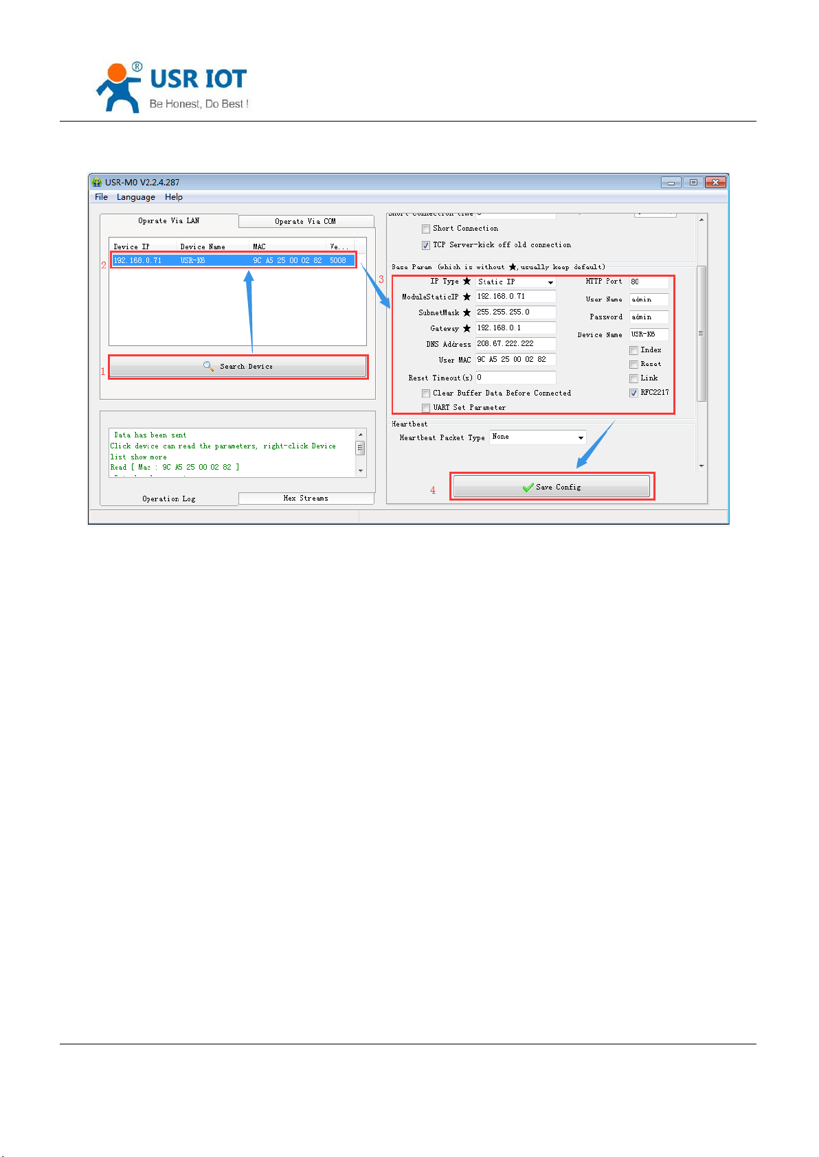
5. Software setting:
From4.1.1-1 Related AT Command
Jinan USR IOT Technology Limited 18 / 107 [email protected]
Page 19
USR-K6 User Manual www.usriot.com
diagram 4.1.1-1 Software Setting
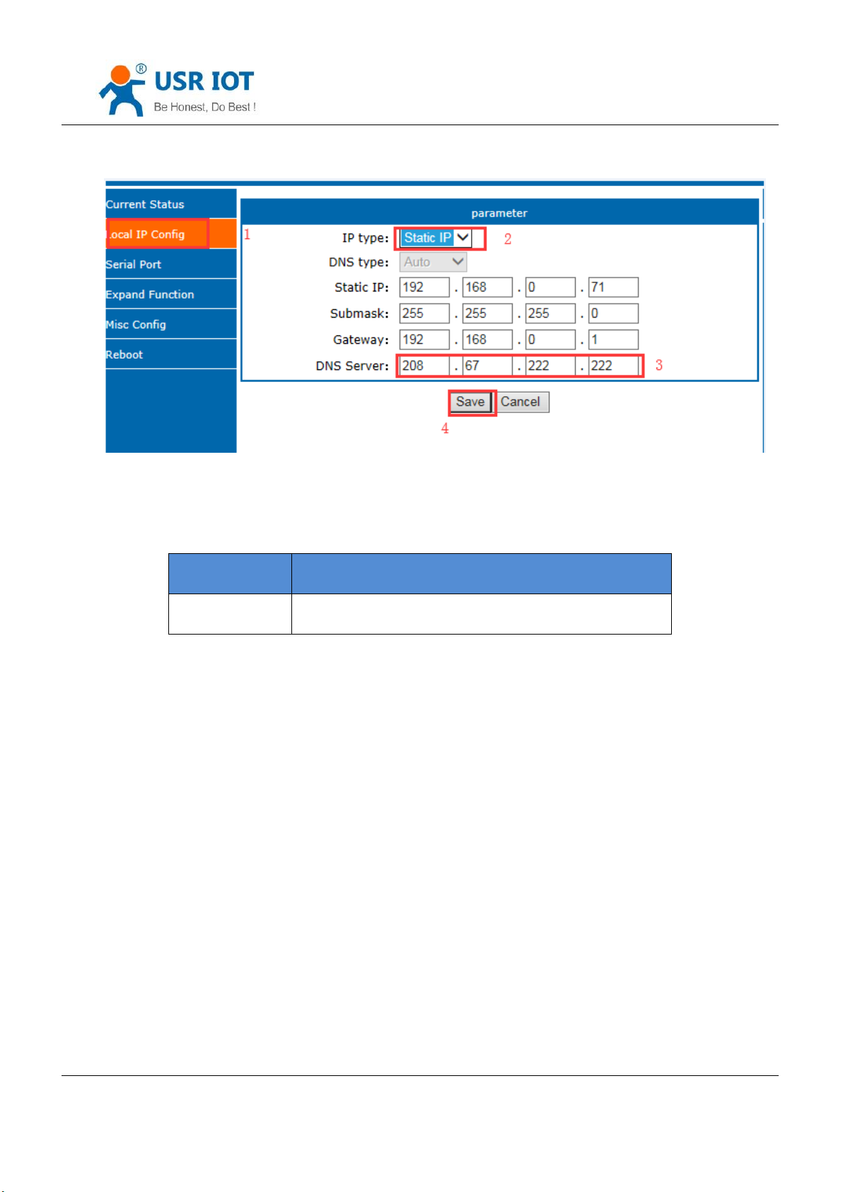
4.1.2. DNS Server Address
DNS servers are used to convert domain names into IP addresses that are recognized by the network. DNS server
address can be set, which can realize domain name resolution in the case of imperfect local domain name server. Users
can also set the address of specific DNS server according to requirements. When K6 needs domain name resolution, it
will submit the resolution request to the DNS server set.Using is more flexible and reliable.
In static IP mode, the default DNS server address is 208.67.222.222, and in DHCP mode, the DNS server address is
obtained automatically. Version 4015 above support domain name server address can be set.
Jinan USR IOT Technology Limited 19 / 107 [email protected]
Page 20
USR-K6 User Manual www.usriot.com
command name
Instr
AT+DNS
Setting and query the DNS address of K6
Diagram 4.1.2-1 DNS Setting Webpage
Form 4.1.2-1 Reference AT Command
4.1.3. Web Server
webpage server of K6 is same as the normal webpage server, which is convenient for user to setting parameter
and query the status.
The port of webpage can be setting, default is 80.
Steps:
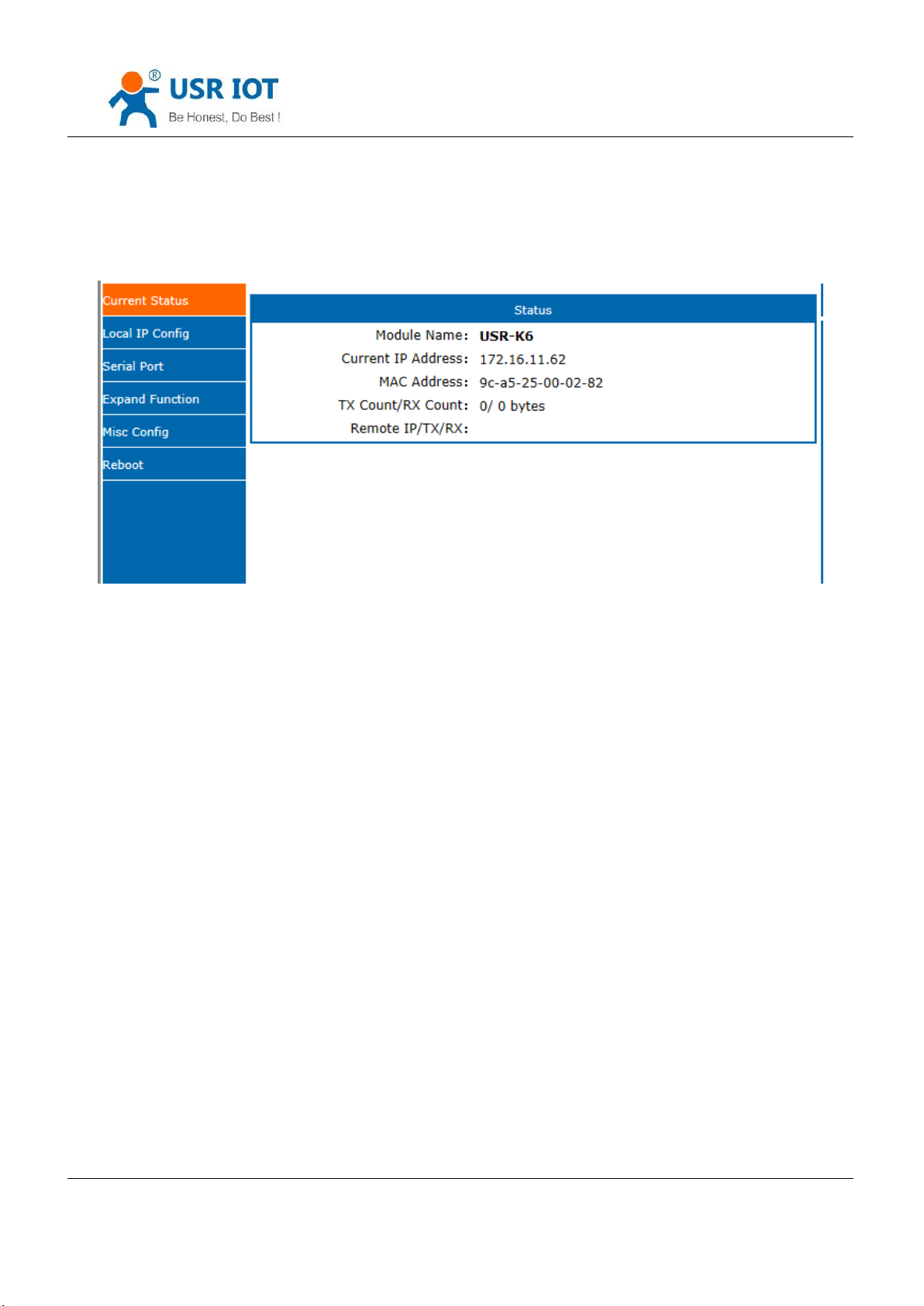
Open the browser, fill the IP of K6, e.g.:192.168.0.7(IP address and PC in the same net segment.)
Fill the user name and key word in the login webpage, default is admin, click to enter.
TX Count: the data count sent from K6 to the external
RX Count: the data count received by K6 from thee net.
Jinan USR IOT Technology Limited 20 / 107 [email protected]
Page 21
USR-K6 User Manual www.usriot.com
Remote IP/TX/RX:via it , you can see the device connected to the K6, and the sent count and received count.
Note: under the UDP server mode, only send/received data, and no connected IP
Diagram 4.1.3-1 Current Status
4.1.4. Restore to the Factory Setting.
1) Hardware restore: K6 supports the hardware restore to the factory setting. Keep putting down reload pin 5s in
powered condition, the put up and it will restore.
Steps:power on→keep the reload pin down→keep for 5s→put up.
2) Software restore: via the software setting and the net protocol sending command.
3) AT command restore: enter the AT command, AT +RELD to restore.
4.1.5. Network Upgrade Firmware
Webpage upgrading firmware, stable and simple. Using this new function meets the custom requirement. If you
need to upgrade, you can query us from the USR support:http://h.usriot.com and asking firmware from supply. The way
to upgrade please reference5.1.1.
4.2. Socket
Jinan USR IOT Technology Limited 21 / 107 [email protected]
Page 22
USR-K6 User Manual www.usriot.com
command name
instr
AT+sock
Setting the work mode/target IP/ target port
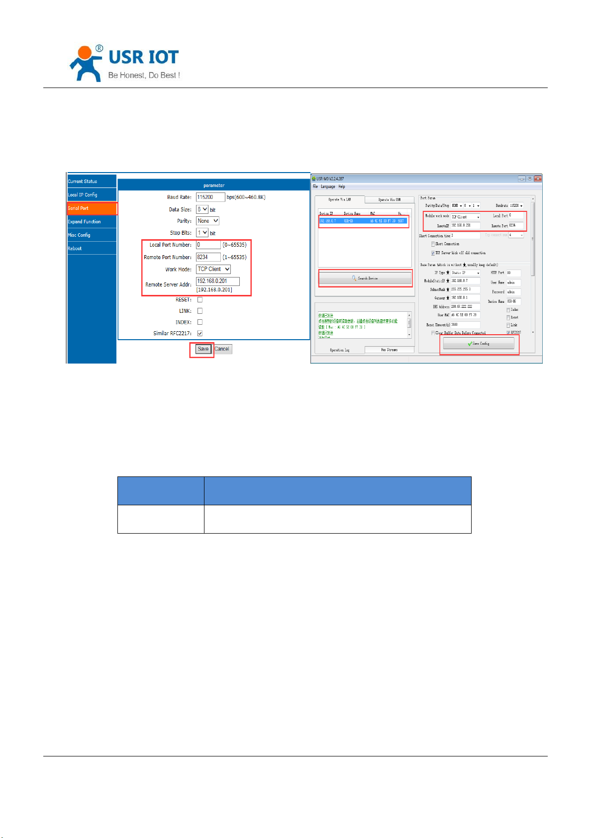
There are five work modes for K6, including TCP Client, TCP Server, UDP Client, UDP Server and Httpd Client.
Setting from the webpage and the software setting, as below:
Diagram 4.2-1 Work mode Setting
Note: Default IP address and type is static IP at 192.168.0.201. Default remote port:8234
Related AT command:
Form 4.2-1 Related AT Command
Jinan USR IOT Technology Limited 22 / 107 [email protected]
Page 23
USR-K6 User Manual www.usriot.com
4.2.1. TCP Client
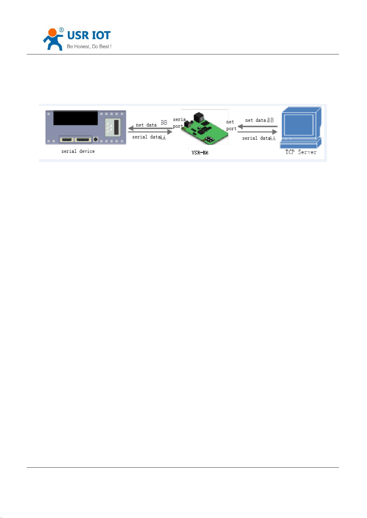
Diagram 4.2.1-1 TCP Client
It has to be connected before transferring data.
1) In TCP Client Mode, K6 connects TCP Server actively, establish a connection to transmit date. According to the
TCP protocol related rule, there difference for TCP client between connect and disconnect, to make sure the data
exchange more stable. Usually used in the data interaction between device and server, which is the most common form
of network communication.
2) In TCP Client Mode, support the function of identifying disconnected link. When connected, it will send
keepalive package every 15s. If unconnected, it can be detected timely and enforce K6 to disconnect the former link to
establish a new one.
3) When K6 try to connect remote server, if the local port number is not “0" ,it will establish a connection with the
same source port every time.
4) Support synchronizing baud rate, USR-cloud and short connection function.
5) In a LAN, if the K6 is static IP, please keep K6 IP stay in the same network segment with gateway, and setting the
gateway IP, otherwise can not work as normal.
6) note:keepalive, synchronizing baud rate and USR-cloud are more on the below.
7)Communication example
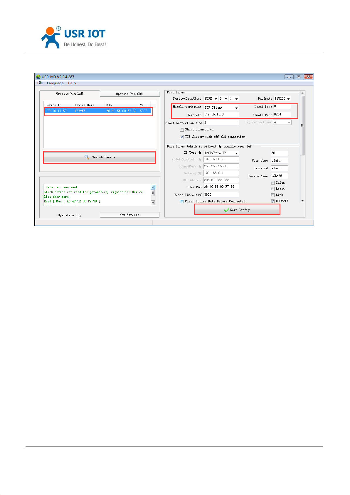
① Software setting, take the K6 as a TCP client, remote IP:192.168.0.201,(for my PC is 172.16.11.8, so for the
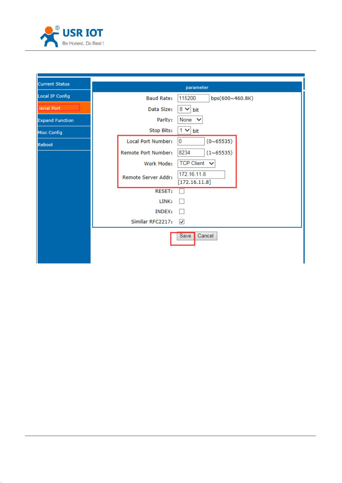
next testing ,change remote IP to 172.16.11.8) remote port:8234, then save it. Research to make sure the parameters
are right. Also you can set work mode, remote IP and remote port in the webpage then save and restart.
Jinan USR IOT Technology Limited 23 / 107 [email protected]
Page 24
USR-K6 User Manual www.usriot.com
Diagram 4.2.1-2 TCP Client Software
Jinan USR IOT Technology Limited 24 / 107 [email protected]
Page 25
USR-K6 User Manual www.usriot.com
Diagram 4.2.1-3 TCP Client Webpage Setting
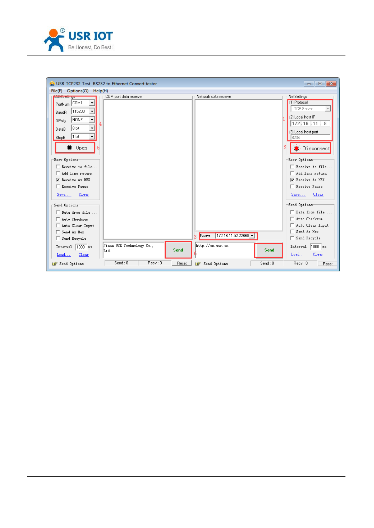
② set the testing software as TCP server, local IP is the IP of the PC ,locally is 192.168.0.201, listen port is 8234
and click listening. Testing software show the 192.168.0.7:4117(distribute randomly). setting the right serial port
parameters and open the serial port.
Note : default remote IP is192.168.0.201.But in order to keep the device and PC in the same network segment to make
the communication correct so we change IP type as DHCP. Just likes the above picture.
③ Click send to receive the bi-direction data.
Jinan USR IOT Technology Limited 25 / 107 [email protected]
Page 26
USR-K6 User Manual www.usriot.com
Diagram 4.2.1-4TCP Connection Testing
Jinan USR IOT Technology Limited 26 / 107 [email protected]
Page 27
4.2.2. TCP Server
USR-K6 User Manual www.usriot.com
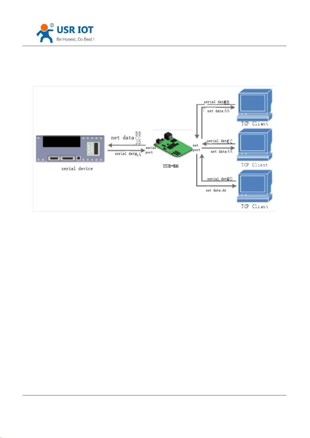
Diagram 4.2.2-1 TCP Server
1) In TCP Server Mode, K6 listens local port, it will response and establish a connection when there is a request. When
the K6 receive the data, it will send it to all the client connected to K6, meanwhile, this mode can monitor the connect
timely with keepalive function.
2) Usually it is used in the LAN communicating with TCP client. Adopt the case that more than one PC or phone asking
data without server. Same as the TCP client ,there are different between connect and disconnect.
3) Support synchronizing baud rate.
4) TCP Client number is from 1 to 16, default value 4. the port is fixed., can not be set to 0.
5) If the number of the TCP client is more than 16, default kick the old one, and this function can be set via webpage.
6) TCP server example
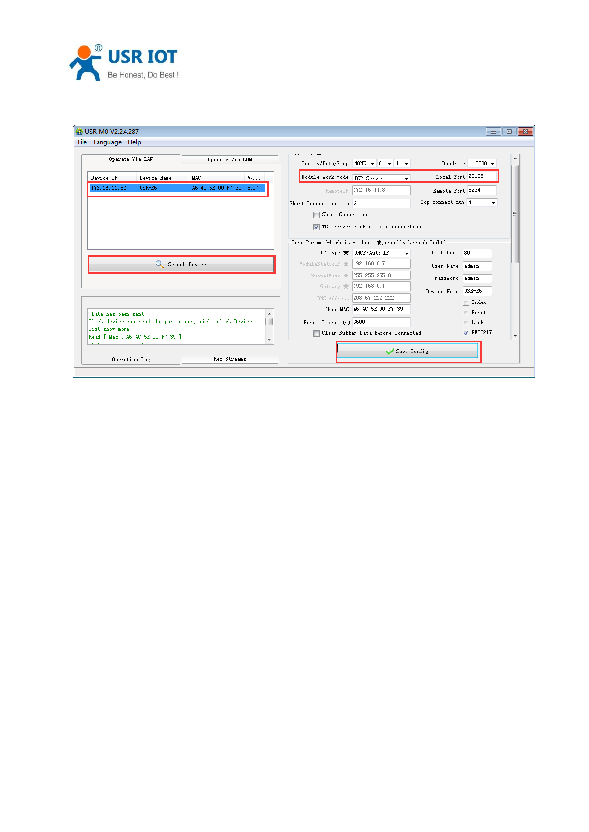
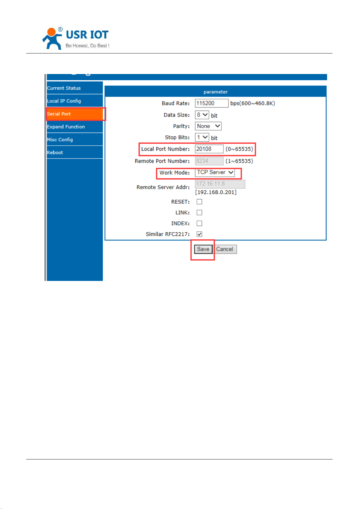
① Set K6 as a TCP server via software setting, local port is 20108, then save. Also you can set via webpage.
Jinan USR IOT Technology Limited 27 / 107 [email protected]
Page 28
USR-K6 User Manual www.usriot.com
Diagram 4.2.2-2 TCP Server Software Setting
Jinan USR IOT Technology Limited 28 / 107 [email protected]
Page 29
USR-K6 User Manual www.usriot.com
Diagram 4.2.2-3 TCP Server Webpage Setting
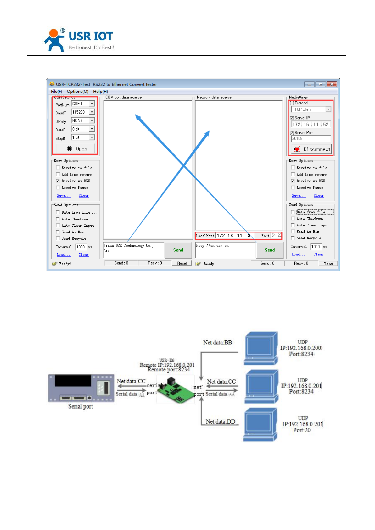
② Testing software set to be TCP client, server IP is IP of K6 and the server port is port of the K6, then connect.
Jinan USR IOT Technology Limited 29 / 107 [email protected]
Page 30
USR-K6 User Manual www.usriot.com
4.2.3. UDP Client
Diagram 4.2.2-4 TCP Server Testing
Jinan USR IOT Technology Limited 30 / 107 [email protected]
Page 31
USR-K6 User Manual www.usriot.com
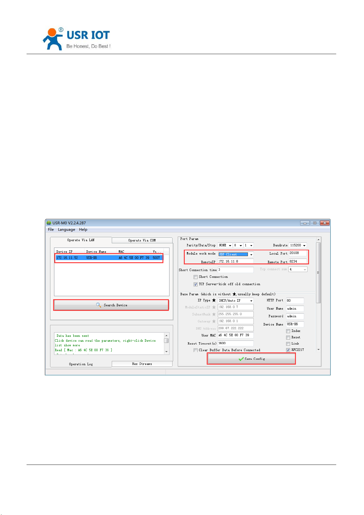
Diagram 4.2.3-1 UDP Client
1) The Model belongs to UDP Protocol.
2) In UDP Client Mode, TCP232-K6 won’t establish the connection actively.
3) It can communicate with the target port whose IP has been set. If data doesn’t come from this channel, it will not be
accepted by TCP232-K6.
4) In UDP Client Mode, if target IP is set as 255.255.255.255, it can realize function of entire network broadcast, also
can receive broadcast data. 4015and the later vision support broadcast. e.g.xxx.xxx.xxx.255.
5) Example
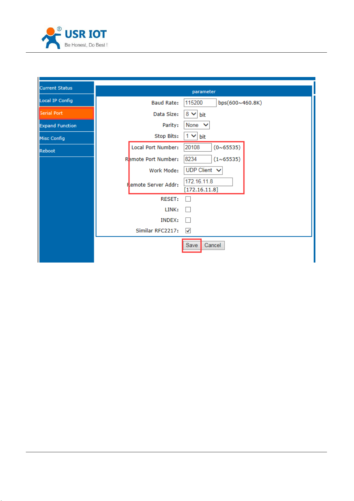
① Set the K6 as UDP client, remote port 8234
Diagram 4.2.3-2 UDP Client Software Setting
Jinan USR IOT Technology Limited 31 / 107 [email protected]
Page 32
USR-K6 User Manual www.usriot.com
Diagram 4.2.3-3 UDP Client Webpage Setting
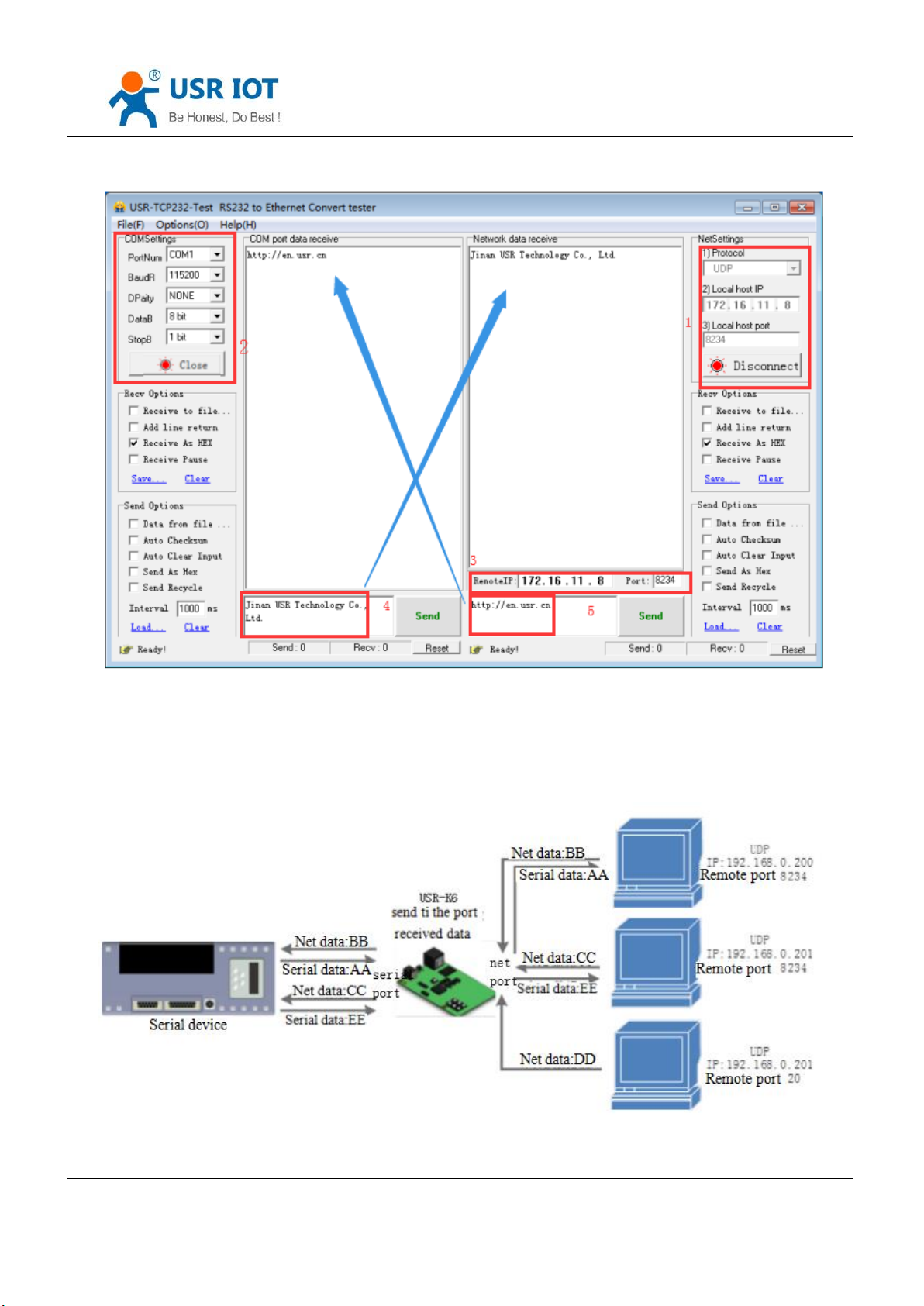
② Set the testing software as UDP, local IP is the IP of the PC, local port is the remote port for K6, the connect.
Setting the correct serial parameters and click to open the serial.
③ Send the send of the serial and receive the data,testing software remote IP and remote port change into the
IP and port of K6, then click the net send, send data to serial port.
Jinan USR IOT Technology Limited 32 / 107 [email protected]
Page 33
USR-K6 User Manual www.usriot.com
4.2.4. UDP Server
Diagram 4.2.3-4 UDP Connection Testing
Jinan USR IOT Technology Limited 33 / 107 [email protected]
Page 34

USR-K6 User Manual www.usriot.com
Diagram 4.2.4-1 UDP Server
1) UDP server is a IP address do not verify the resource in the normal UDP. After receive every UDP package,
change the target IP into data resource IP and port. When sending data, sending to the least IP and port.
2) Usually this mode, several net device communicate with module and do not want to use TCP for high frequency.
3) Example:
① Set the K6 as UDP server, local port is 20108
② Open the testing software, choose UDP and the local IP is IP of the PC, set the ports to be different, e.g. 23
and 8234 in the below diagram, then click.
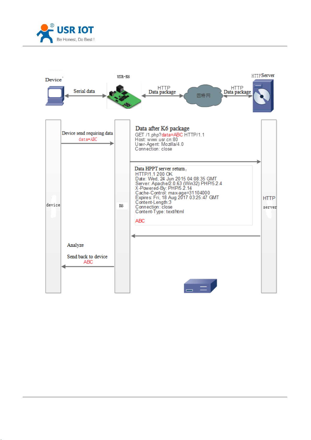
4.2.5. HTTPD Client
In this mode , users’ terminal device can send required data to assigned HTTPD server via K6, and then, K6 receives
the data from HTTP server, analyzes the data and sends the result back to the serial port.
No need for paying attention to the process of data conversion between the serial data and net data package.
Simple parameter setting can realize the requirement serial device sent to HTTP server.
Jinan USR IOT Technology Limited 34 / 107 [email protected]
Page 35
USR-K6 User Manual www.usriot.com
Diagram 4.2.5-1HTTPD client
Jinan USR IOT Technology Limited 35 / 107 [email protected]
Page 36
USR-K6 User Manual www.usriot.com
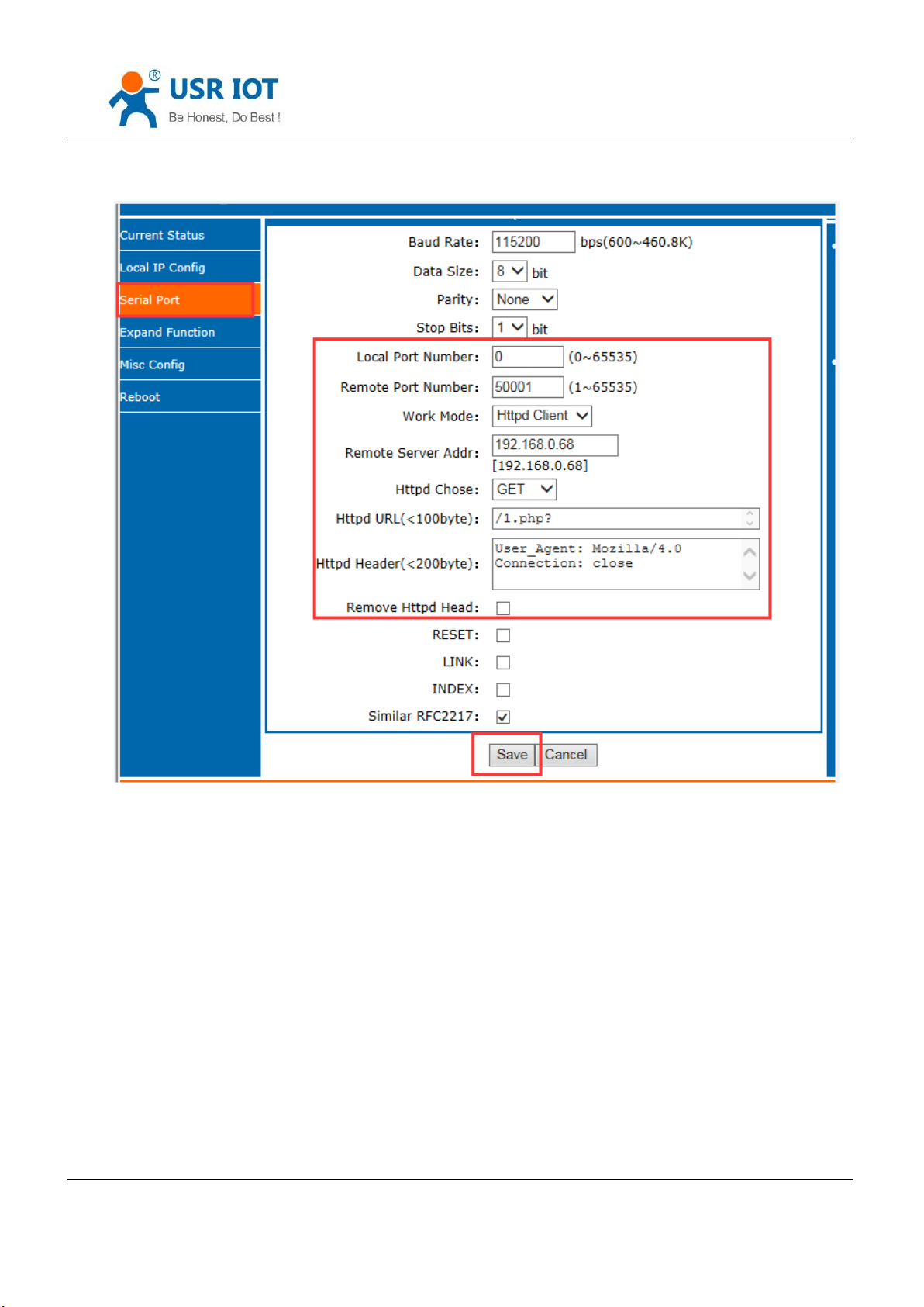
Diagram 4.2.5-1HTTPD client Webpage
1.Setting K6 as Httpd Client mode via webpage, and setting corresponded remote port and remote IP.
2.Setting the way to requirement of the Httpd and the URL and the package head information of the requirement
package.
3.The return data whether drop the package head can be set by webpage:remove HTTPD head
4.Click save, then restart to work.
5.Open serial port to send data, then the data of the serial port will submit to your webpage, meanwhile the serial
port will receive the reply.
Jinan USR IOT Technology Limited 36 / 107 [email protected]
Page 37
USR-K6 User Manual www.usriot.com
4.2.6. VCOM
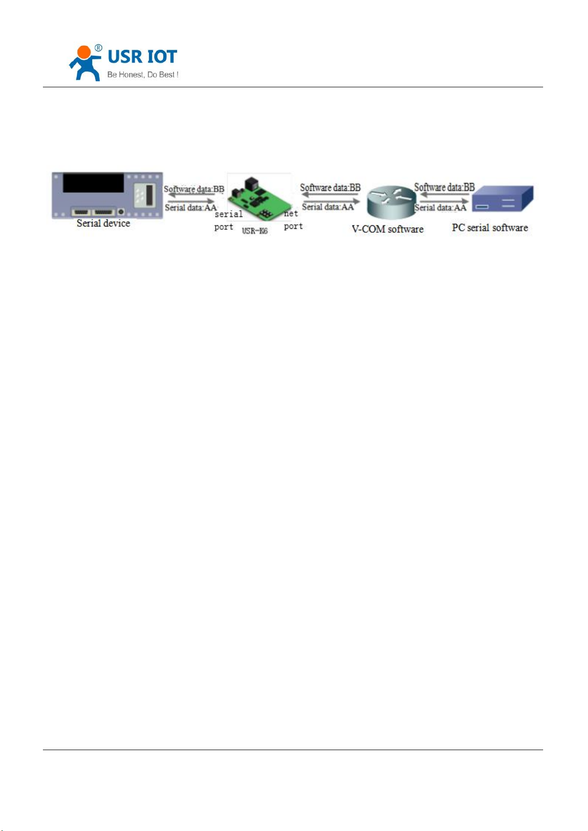
Diagram 4.2.6-1 VCOM
Receive the data assigned VCOM data, and send it in the data of net data using VCOM to solve the PC as a serial
port and can not connect with device,which is convenient for users.
E.g.
1. Take K6 in TCP Server mode as a server, which is convenient for user to change the computer and connected.
2. Setting the way to connect the VCOM and K6 manually:
① Open the VCOM and add the serial port, choose the port: COM2(avoid the exist COM port) protocol use the TCP
client, remote IP set to the IP of the K6, remote port is the port of the K6. note fill the device name.
② Click sure, observe if the connection is established, if the connection has established, and you can test the data
transport transmission.
3.More information reference the below:
http://www.usr.cn/Search/getList/keyword/%E8%99%9A%E6%8B%9F%E4%B8%B2%E5%8F%A3/
4.3. Serial Port Function
Jinan USR IOT Technology Limited 37 / 107 [email protected]
Page 38
4.3.1. Basic Parameters
USR-K6 User Manual www.usriot.com
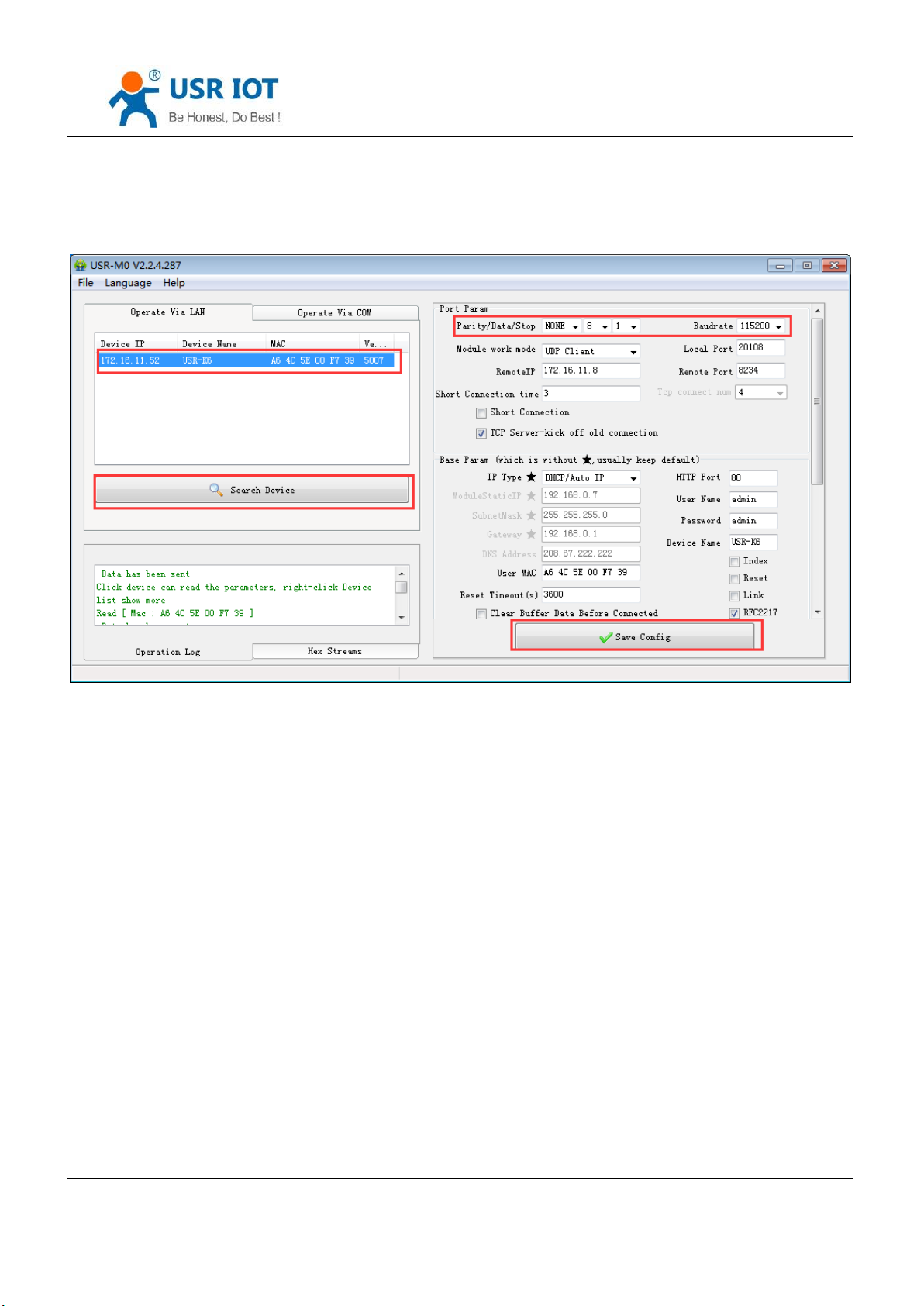
Diagram 4.3.1-1 Basic Parameters
Serial port basic parameters including: baud rate; data bits; stop bits; parity.
1.Baud rate: communicating speed of serial port, can be set from 600~460.8Kbps, support random baud rate.
2.Data bits:the range of it from 5to 8.
3.Stop bits:can set from 1 to 2.
4.Parity: support none, odd, even, mark and space
4.3.2. Serial Port Framing
Since the data on the network is transmitted in the unit of data frames, it is necessary to send the frame data via
serial port to the network, so as to transmit data more efficiently and quickly.K6 packages serial port data according to
fixed packaging length and packaging time during data transmission.The default K6 packaging time is 4 bytes of
packaging time and 400 bytes of packaging length.
Jinan USR IOT Technology Limited 38 / 107 [email protected]
Page 39

USR-K6 User Manual www.usriot.com
The frame mechanism of serial port is based on the packaging time and the packaging length.
1. Serial port packaging time: the default is 4 bytes of send time.
The default package time of K6, the interval that serial port receive time more than 4 bytes packaging time, K6
packaging sending. E.g. baud rate is 115200K time for 4 bytes is 0.4ms, if the value less than 0.1ms, the package time
calculate as 0.1ms. A formula to calculate as fellows:
T=1/baud rate*10*4
2. Serial port package length: default package length is 400 bytes
When K6 receive data from webpage, and then send to serial port. For the limited of the serial speed, the user
need to control the flow, otherwise data overflow problems can be occur and drop the package. So when send data
from network to serial port, please calculate the flow.
Calculate way: if sending M bytes need N s. the way to check for possible overflow methods (if the net situation is
ok, the time can be ignored ). The time for M bytes:
T=1/baud rate*10*m
If there is no overflow, M bytes of data must be transmit within Ns, then N>2T is require for K6 to work properly.
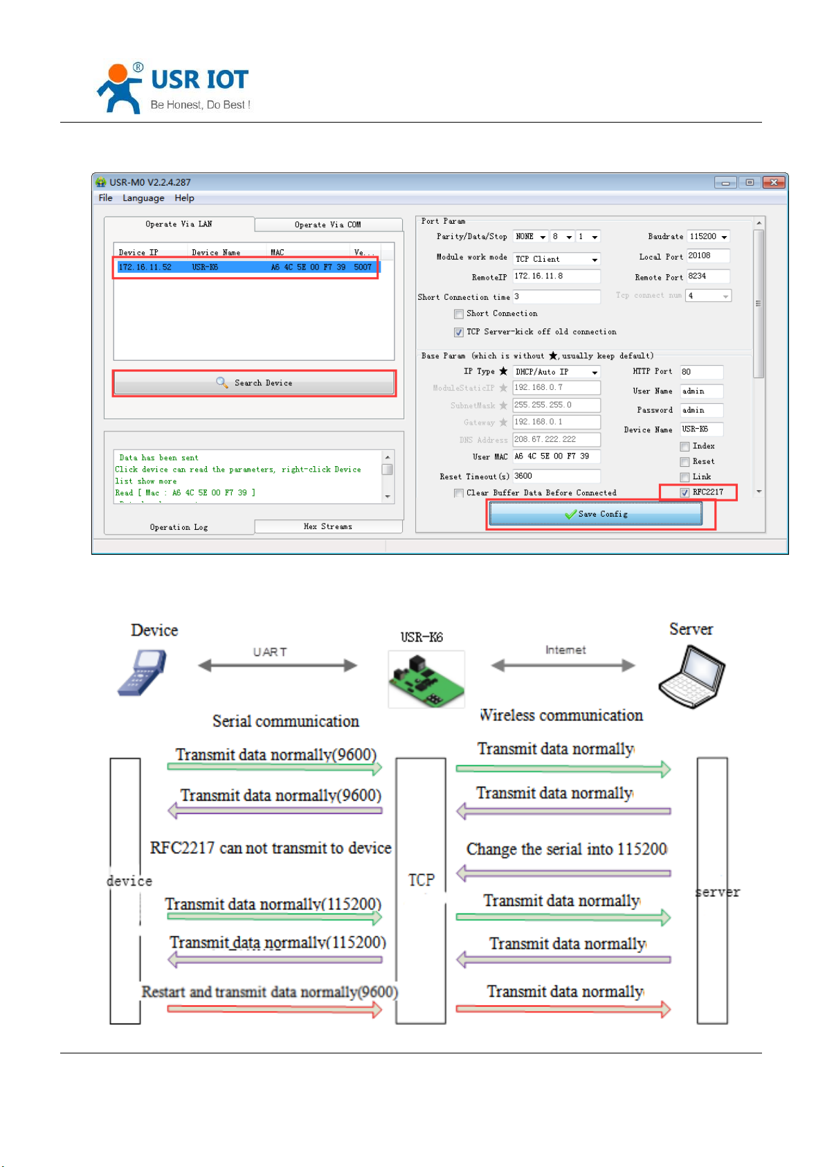
4.3.3. RFC2217
Similar RFC2217 is a simple RFC2217 protocol, working with the VCOM and changing serial port parameters
candynamically to realize the communication with variable serial port parameters.
Enable this function, using USR-VCOM can open this function,which can realize the serial baud of the PC software
and K6 automatically match. No need to pay attention to serial port baud rate setting.
Jinan USR IOT Technology Limited 39 / 107 [email protected]
Page 40
USR-K6 User Manual www.usriot.com
Diagram 4.3.3-1 Similar RFC2217 Function
Jinan USR IOT Technology Limited 40 / 107 [email protected]
Page 41
USR-K6 User Manual www.usriot.com
name
Package head
Baud rate
Median
parameter
Parity sum
bytes
3 3 1
1
instr
3 byte to reduce
miscalculation
High in front, and the
minimum is 600( 00 02 58 )
data/stop/parity,
next chart
Four sum except the
package head .
115200,N,8,1
55 AA 55
01 C2 00
03
C6
9600, N,8,1
55 AA 55
00 25 80
03
A8
A no.
instr
value
Describe
1:0
data bits select
00
5 data bits
01
6 data bits
10
7 data bits
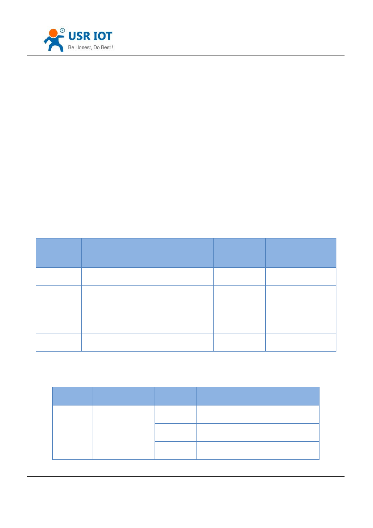
Diagram 4.3.3-2 RFC2217 Function
Modify the serial port baud rate from 115200bps to 9600bps. FRC2217 can be set using software or webpage,
default is enable.
This function modify from RFC2217, promote the certainty for transmission. Length is 8 bytes.detailed note and
the protocol content are as fellows(e.g. value is HEX).
① Send the protocol to the device, if the requirements are met, the serial port parameters shall be set, and no
transparent transmission, if there is something wrong, the data package will be forwarded through the serial port as
ordinary data.
② TCP Client, TCP Server, UDP Client, UDP Server and radio support this function.
③ The modify of this order effect in time, do not restart. Effective during this operation cycle, will not save, power
loss.
Jinan USR IOT Technology Limited 41 / 107 [email protected]
Form4.3.3-1 RFC 2217 Function Protocol
Page 42

USR-K6 User Manual www.usriot.com
11
8 data bits
2
stop
00
1 stop
01
2 stop
3
Parity enable
00
Disable parity
01
Enable parity
5:4
Parity type
00
ODD
01
EVEN
10
Mark
11
Clear
7:6
none
00
Please fill 0
Form4.3.3-2 Serial Port Parameters Basic Meaning
④ Enable Note:
1) When using RFC2217, click setting software RFC2217 to enable this function.
2) When the serial port parameters change, send the RFC2217 package, after K6 received the RFC2217 command,
modify the serial parameters and can not transparent transmission.
⑤ E.g.
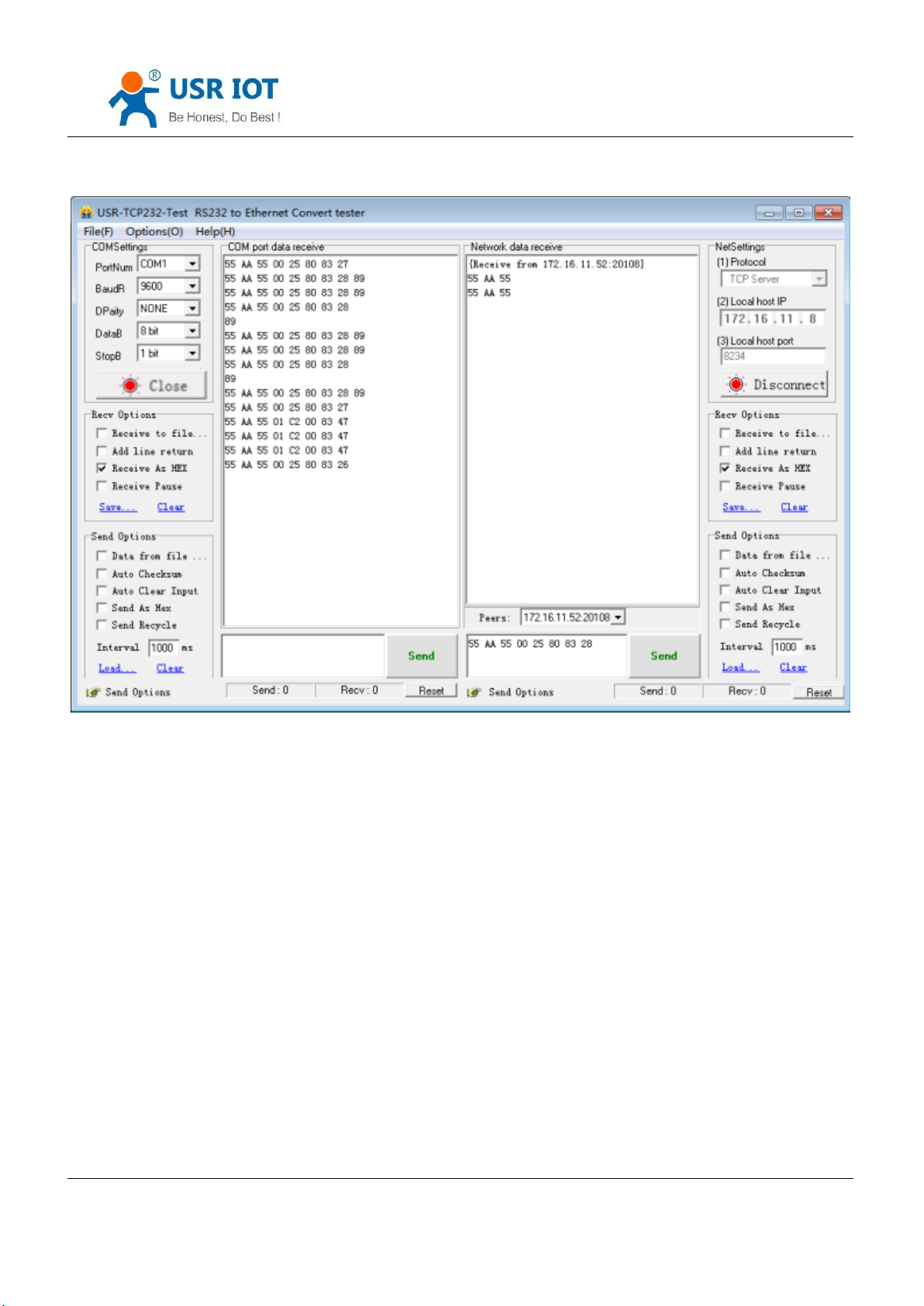
Protocol command:
55AA5501C2008346 setting serial port parameter is 115200 N,8,1
55AA550025808328 setting serial port parameter is 9600 N,8,1
Jinan USR IOT Technology Limited 42 / 107 [email protected]
Page 43
USR-K6 User Manual www.usriot.com
Diagram 4.3.3-3 Testing
4.4. Special Function
4.4.1. Heartbeat Package
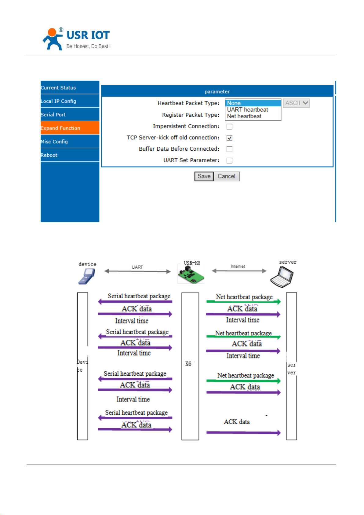
In the transparent transport mode, user can choose K6 to send heartbeat package. Heartbeat package can be sent
to net server, also can send to serial port, but can not send in the same time.
Sending to the net aimed at connecting with server, effect only in TCP client and UDP client.
In the application of the server sending fixed query command to device, to reduce the communication flow. The
user can choose using the serial port to send the heartbeat package instead of the heartbeat from server.
4015 and the later vision support heartbeat package. The longest content is 40 bite.
Jinan USR IOT Technology Limited 43 / 107 [email protected]
Page 44
USR-K6 User Manual www.usriot.com
Diagram 4.4.1-1 Heartbeat Webpage
Jinan USR IOT Technology Limited 44 / 107 [email protected]
Page 45
USR-K6 User Manual www.usriot.com
Diagram 4.4.1-2 Heartbeat Function
4.4.2. Registration package
In the transparent transport mode, user can choose K6 to send registration package. Registration package is used
to identify data sources or do as the code to get the server authorization.
Registration package can be sent when the K6 built connection with server, also can installed in the head of the
data package, as a data package. Registration package data can be MAC address or customize registration package data,
where the custom registry setting content is up to 40 bytes.
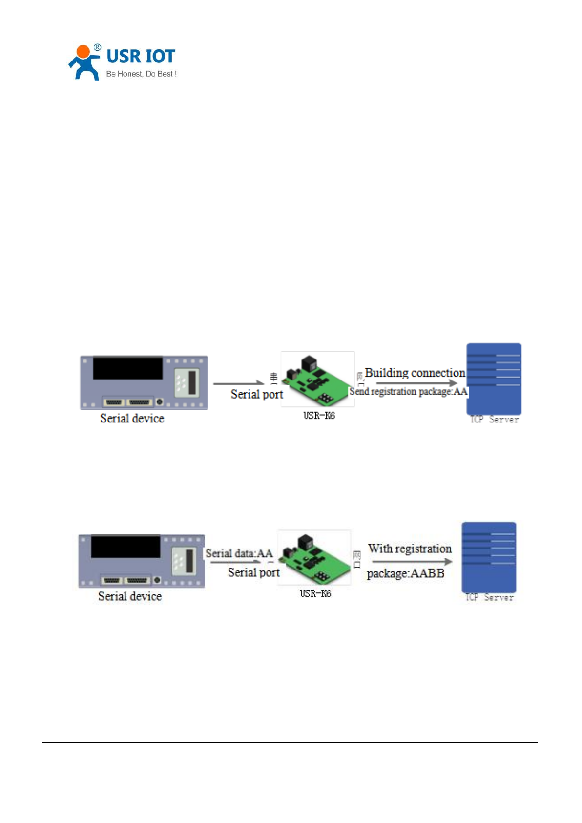
The connection setting and sending registration package is mainly used to connect the server that needs to be
registered. The application diagram is as follows:
Diagram 4.4.2-1 Building the Connection to Send Registration Package
Data carries the registration package: sending data in the front of the data access to the registration
package,mainly for protocol transmission application diagram is as follows:
Jinan USR IOT Technology Limited 45 / 107 [email protected]
Page 46
USR-K6 User Manual www.usriot.com
Diagram 4.4.2-2 Data with Registration Package
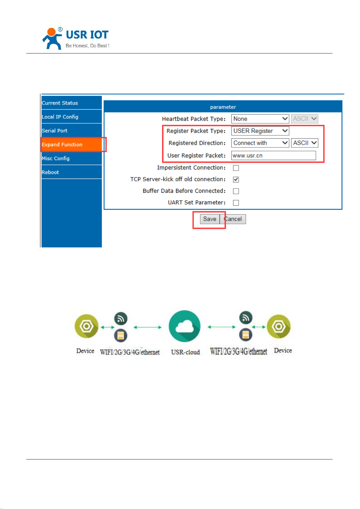
Diagram 4.4.2-3 Registration Package Webpage
4.4.3. USR-cloud
Diagram 4.4.3-1 USR-cloud
USR-Cloud software is a platform for communication between devices and PC software. The cloud software is mainly
used for data transmission or monitoring remotely. This function only works in TCP client mode.
Login link of USRIOT Cloud: http://console.usriot.com
Remote server address: console.usriot.com
Jinan USR IOT Technology Limited 46 / 107 [email protected]
Page 47
USR-K6 User Manual www.usriot.com
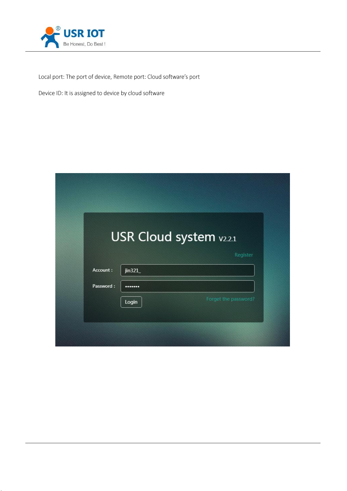
Communications Code: Pass word generated after adding the device to cloud software
The following is test account of USR-Cloud:
Account: jin321_
Password: 1987322
Jinan USR IOT Technology Limited 47 / 107 [email protected]
Page 48
USR-K6 User Manual www.usriot.com
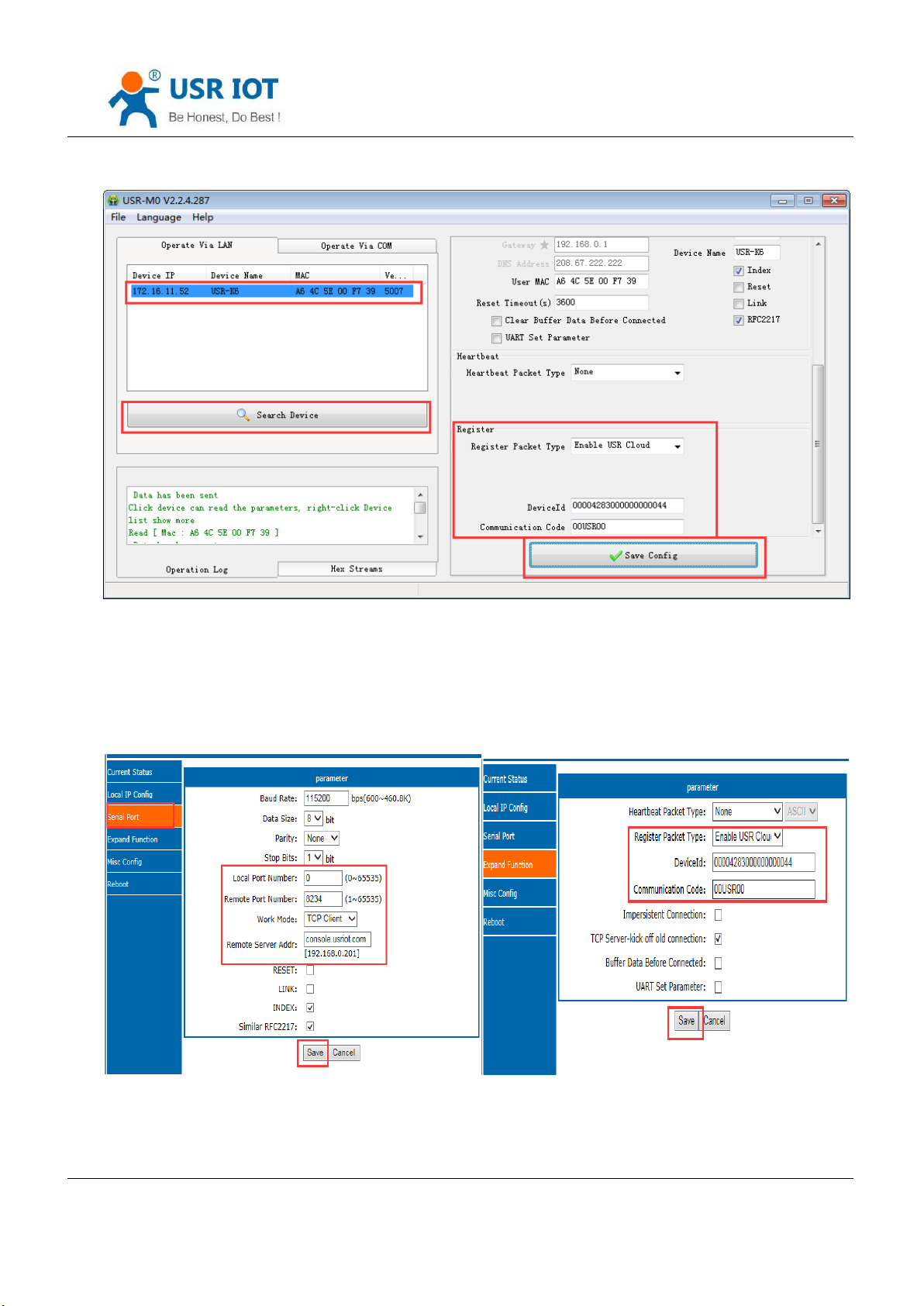
Diagram 4.4.3-2 USR-cloud Software Setting
Note: Module needs work at TCP client
Also can be set in the webpage as fellows:
Jinan USR IOT Technology Limited 48 / 107 [email protected]
Page 49
USR-K6 User Manual www.usriot.com
Diagram 4.4.3-3 USR-cloud Webpage Setting
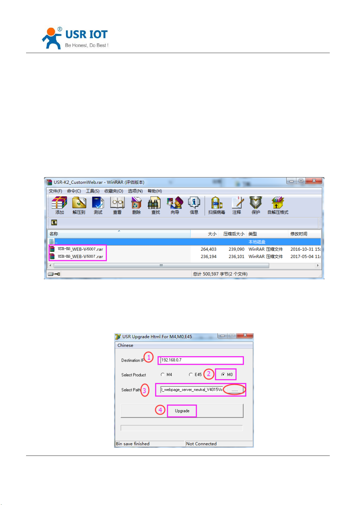
4.4.4. Customize webpage
K6 support customize webpage. The user can upgrade their webpage into K6 via customize webpage. To be more
convenient for user, we have prepared upgrade webpage package in our website:
https://www.usriot.com/support/downloads/customized-webpage-usr-tcp232-K6-s2-customized-webpage-v4017.html
Including webpage code, webpage tools can be download.
Diagram 4.4.4-1 Package
Upgrade webpage need to notes that, destination IP set to be the IP address of K6, the final name of file is
“fs”,product choose the”M0”, then click the upgrade.
Jinan USR IOT Technology Limited 49 / 107 [email protected]
Page 50

USR-K6 User Manual www.usriot.com
Diagram 4.4.4-2 Webpage Upgrade
4.4.5. Link
Link pin can be used as indication pin for TCP connection status. When connected, it output low level; When
unconnected, high level. When K6 is under TCP model, Link pin will pull down. otherwise, it stays in high level. When K6
is under DUP model, Link pin will always pull down. By default, it is not checked.
4.4.6. Reset
Reset used when the K6 fly or crash and can not built the normal connection,so can not work. Reset to initialize
the module to resume normal operation.
When working as TCP Client, K6 connects to TCP Server actively. When start Reset function, K6 try to connect to
TCP Server for 30 times. If failed, K6 will restart automatically. By default, it won’t be chose.
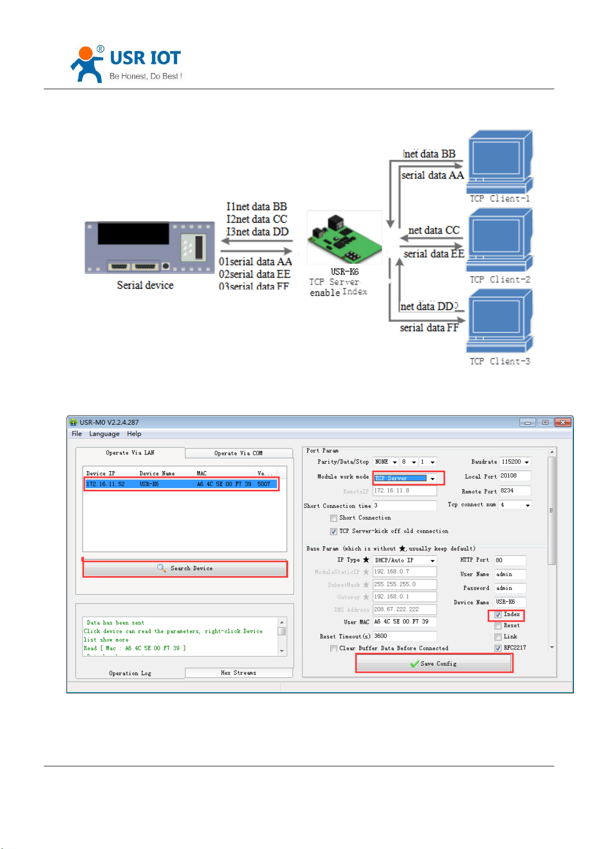
4.4.7. Index
Index is to resolve the problem that under TCP server mode, K6 can not divide the data sources or send data to
special client when user have more than 2 client to connect the K6.
At most there can be 16 links when the K6 in the TCP server mode. The max number can set from 1to 16 as you
want. Here we take the default number is 16 as example. Server send data to 16 clients, or the server receive the data
from 16 clients, open the Index, mark to divide the different clients and user can recognize the data sources according
to the mark, meanwhile send different data to special clients.
Jinan USR IOT Technology Limited 50 / 107 [email protected]
Page 51
USR-K6 User Manual www.usriot.com
Diagram 4.4.7-1 Index Function
Diagram 4.4.7-2 Index Software Setting
1.After the server receive data, output 'I' 'N' data…… to user MCU via server serial port. I means receive; N means
Jinan USR IOT Technology Limited 51 / 107 [email protected]
Page 52
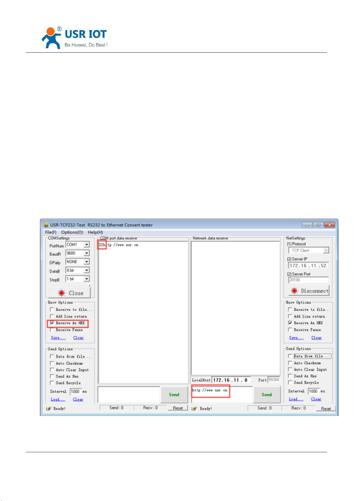
USR-K6 User Manual www.usriot.com
the data from which index ranging from 31 to 40 in hexadecimal.
2.User MCU fill 'O' 'N' data……via the server serial port, O means output, N means using which Index to sending, K6
server send data from serial port to net client port.(note o refers to the character “o”in ASCII and N is the character N,
such as 1,2, etc)
3.K6 server port input 'C' 'N' 'M' to user MCU when the new TCP connected, means the current one is the number
N and on total there are M .
4.When there are 16 client to connected,if there is new connection to ask, input F,F to MCU.
5.Break off it, K6 server input 'D' 'N' 'M' to user MCU, N means the original number of connections deleted, and
remaining M connections.
Data transmission as the below:
Jinan USR IOT Technology Limited 52 / 107 [email protected]
Page 53
USR-K6 User Manual www.usriot.com
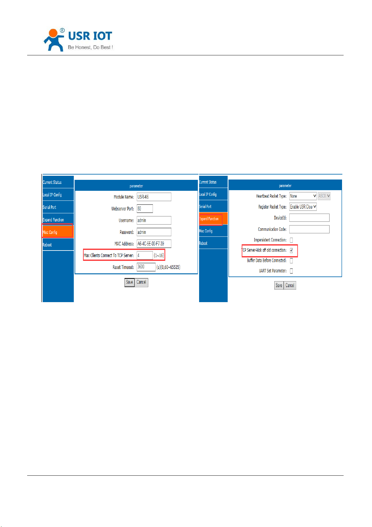
4.4.8. The number of the connected client
USR-K6 works in the TCP server mode, the max number of client to connect is 16, default is 4, the max number can
be configuring as you want, which is be convenient for using. When the the number connecting clients more than 4, we
should control the total data flow in 2.5KB/s if we need to send and receive meanwhile(not more than 200 bite/s).
If the number is 16 now(e.g. the number you set is 16), default use the new link instead of the older one, also you
can set to use the older one. The webpage are as fellow.
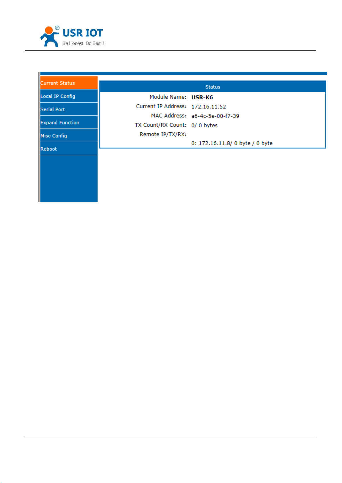
Diagram 4.4.8-1 Webpage
4.4.9. State
In the webpage of the USR-K6, there is the current static page, which can show the current IP and the each
connection sends data and the number of bytes of connection data, along with the total number of bytes sent and
received by the K6 server on the page.
Now, under the TCP client mode, K6 can statistic the former 5 IP of devices and the number of the sent and
received data. Refresh every ten seconds automatically. Under the UDP server mode, the K6 only static the number of
the sent and received data, no connected IP.
Jinan USR IOT Technology Limited 53 / 107 [email protected]
Page 54
USR-K6 User Manual www.usriot.com
Diagram 4.4.9-1 Current Status
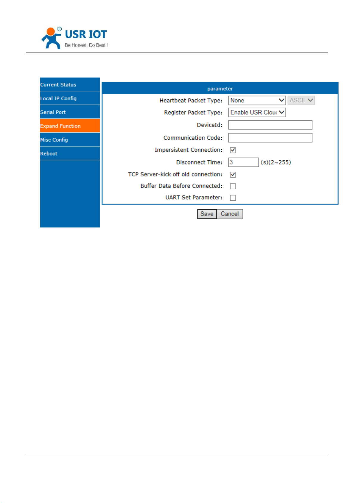
4.4.10. Short Connection
The aim to use this function is to save the resource of the server, usually used in the points to one point. Using the
short connection can sure the current connection is the useful one, no extra control tools to screening.
TCP short connection can sued in the TCP client, open it and send message. The connection will be broken
automatically.
This function default disable, the interval of disconnect can be configured after enable it, the range from 2 to 255s,
default is 3s, the diagram is as fellow:
Jinan USR IOT Technology Limited 54 / 107 [email protected]
Page 55
USR-K6 User Manual www.usriot.com
Diagram 4.4.10-1 Impersistent Connection
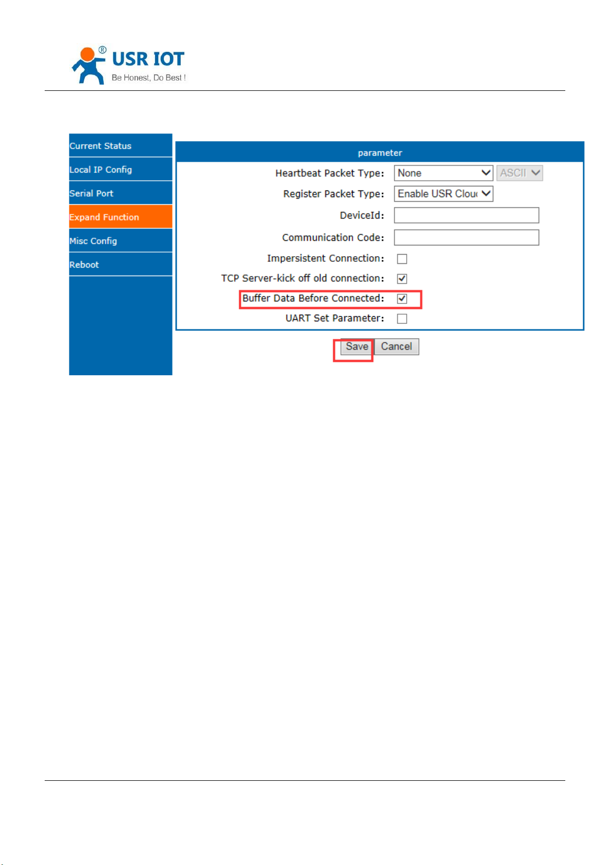
4.4.11. Clear Buffer Data
If the TCP have no connection, the data that serial received will be placed in the cache, and the K6 serial port can
receive 800K byte, after the TCP built, you can select is clear the cached data.
Default disable. Under the Httpd client mode or the TCP client mode, enable the short connection and this
function do not work.
Jinan USR IOT Technology Limited 55 / 107 [email protected]
Page 56
USR-K6 User Manual www.usriot.com
Diagram 4.4.11-1 Clear Buffer Data
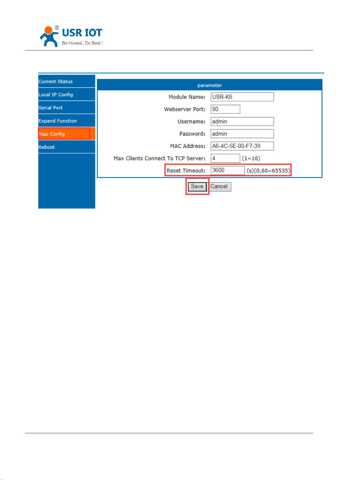
4.4.12. Restart Timeout
Restart timeout is to make sure the long and stable work of K6, when the net port or network can not receive data
for long time, K6 will restart out the setting time to avoid abnormal conditions affect the connection. Time for restart
can set in the webpage. The normal work time of this function set 60~65535s, default is 3600s. if setting time less than
60s, default to be 0 and turn off this function. The setting is as fellow:
Jinan USR IOT Technology Limited 56 / 107 [email protected]
Page 57
USR-K6 User Manual www.usriot.com
Diagram 4.4.12-1 Restart Timeout
5. Parameter Setting
This character mainly to introduce how to setting the K6 parameters and achieve their own personalized
application through parameter settings
Including setting software setting parameter, webpage setting parameter and serial setting parameter.
User setting steps:
Modify the user name and password→ setting the access way to the IP address→ serial parameter→ the related
parameters for working method.
To ensure the normal using of software, the following steps are necessary
1.When using setting software to setting parameter, K6 and the PC of the setting software are in a LAN.
2.Close the antivirus software and firewall software.
3.Close the irrelevant network card.
5.1. Net Protocol Setting Parameters
Jinan USR IOT Technology Limited 57 / 107 [email protected]
Page 58
USR-K6 User Manual www.usriot.com
5.1.1. Setting Software Setting Parameters
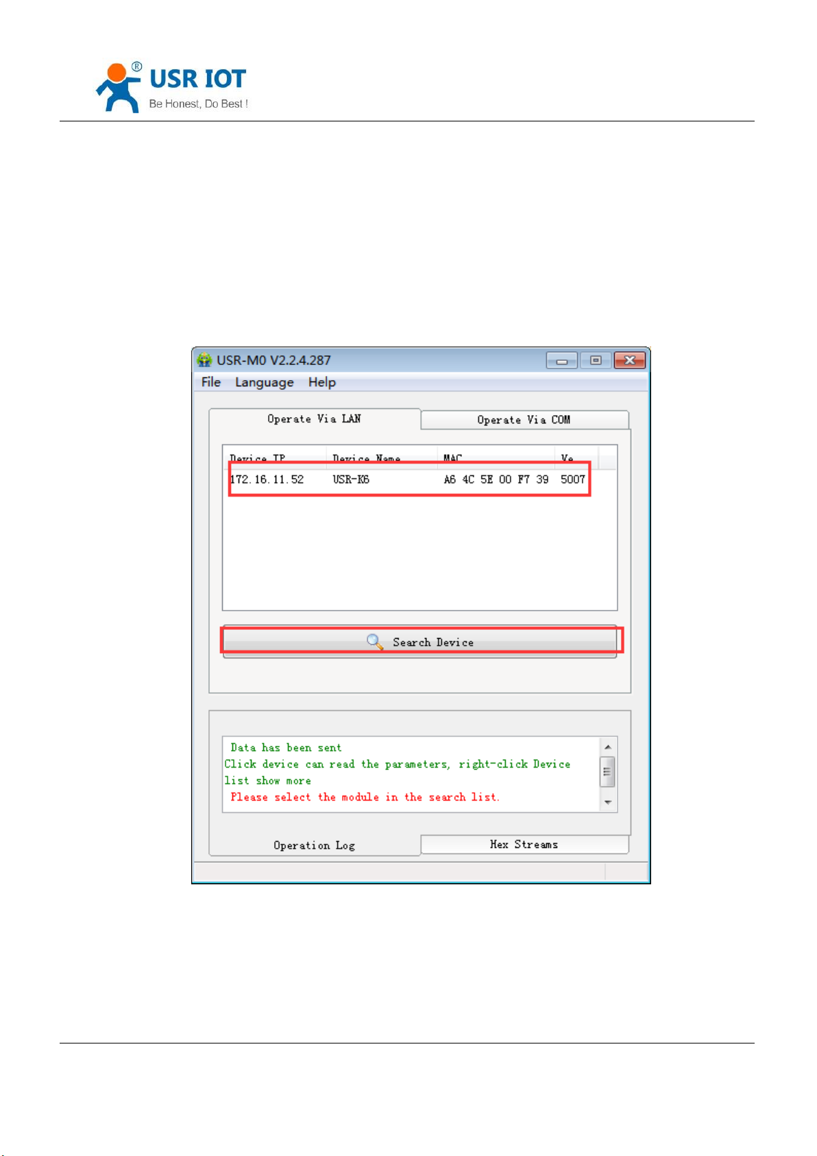
Open the software setting and click search.
Download link: https://www.usriot.com/support/downloads/usr-m0-setup-software-v224288.html
Search all the K6 in the LAN, including current IP, device name, MAC and version of the K6.
Diagram 5.1.1-1 Searching
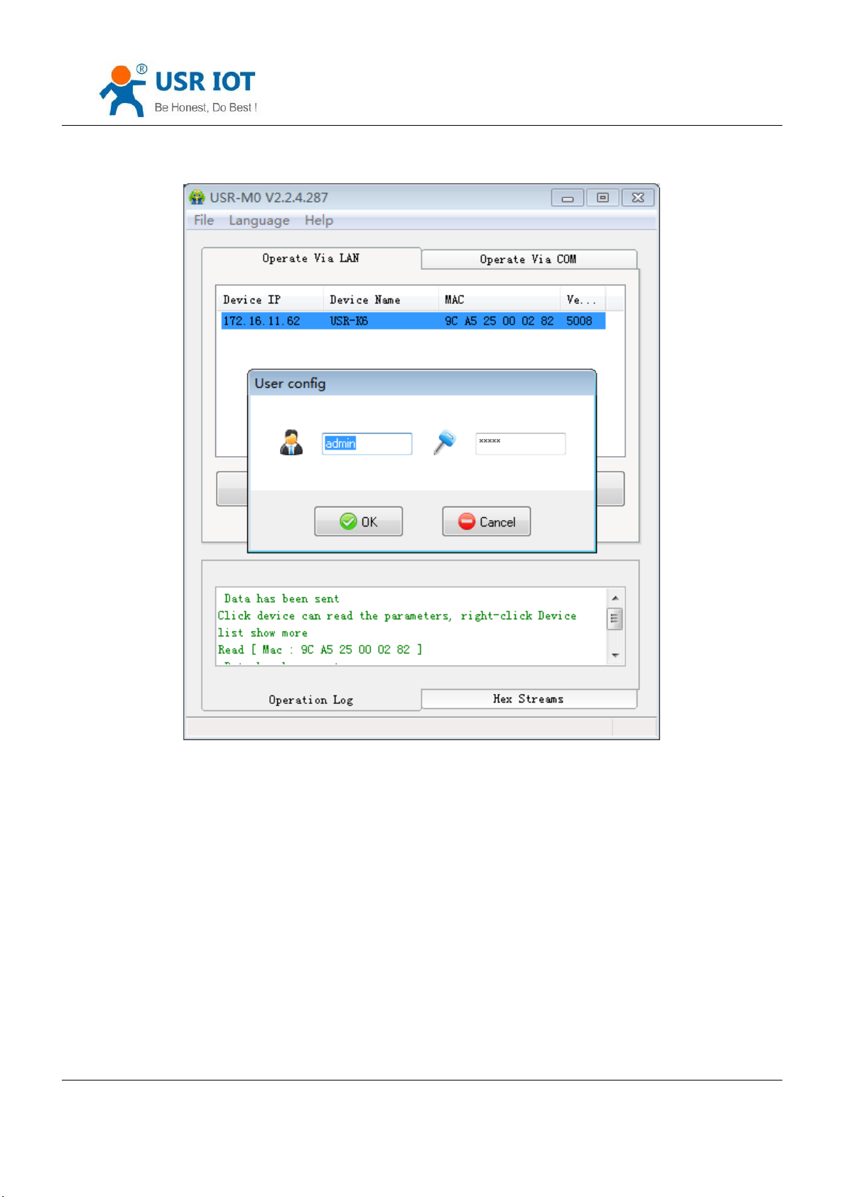
1. Click the k6, enter the password and you can see the detailed parameters of the K6. if wrong, there will be the
window for username and password. Fill them and enter. Default username and password:admin(software setting
default username and password are admin, so under default condition,the setting software will not pop-up the window.
Jinan USR IOT Technology Limited 58 / 107 [email protected]
Page 59
USR-K6 User Manual www.usriot.com
Diagram 5.1.1-2 Username and Password
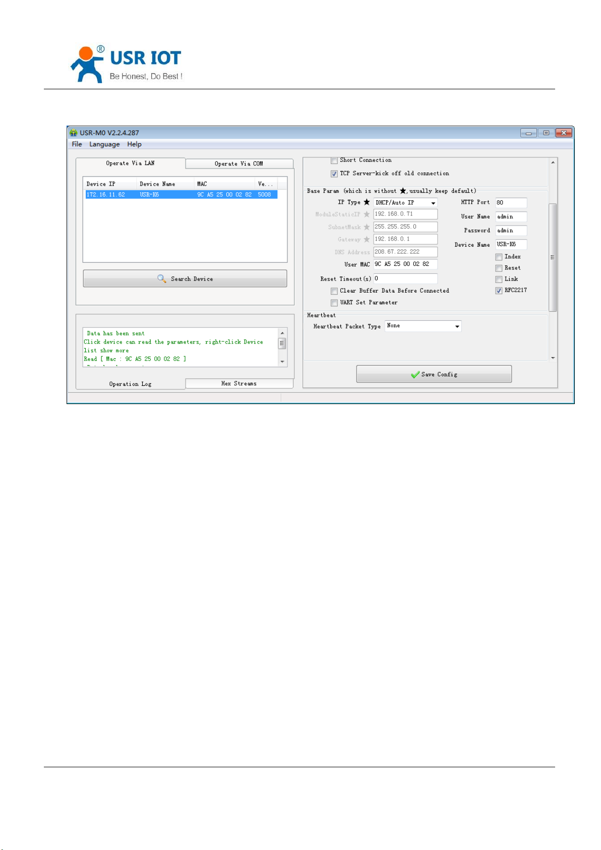
2. Basic parameter setting
Click the searching device and you can see the basic parameters needed to set, combined with the function
introduction of the third chapter, setting the parameter you need, then click the save. Then you are succeed to modify
the parameters you have change, others keep default.
Jinan USR IOT Technology Limited 59 / 107 [email protected]
Page 60
USR-K6 User Manual www.usriot.com
Diagram 5.1.1-3 Basic Parameters
HTTP port: the port default is 80
Username: the login username of K6, the authentication code for modify the parameter, can prevent other users
modify the parameters of K6 in LAN.
Pass word: the password of the K6, correspond with username.
Device name: the K6 name can be customize.
IP type: static IP and DHCP
Static IP: the static IP of K6, please put it in the same LAN when setting it.
Subnet masks: default is 255.255.255.0
Gateway: usually is the router IP, after correct setting you can communicate across the LAN and do the domain
name resolution.
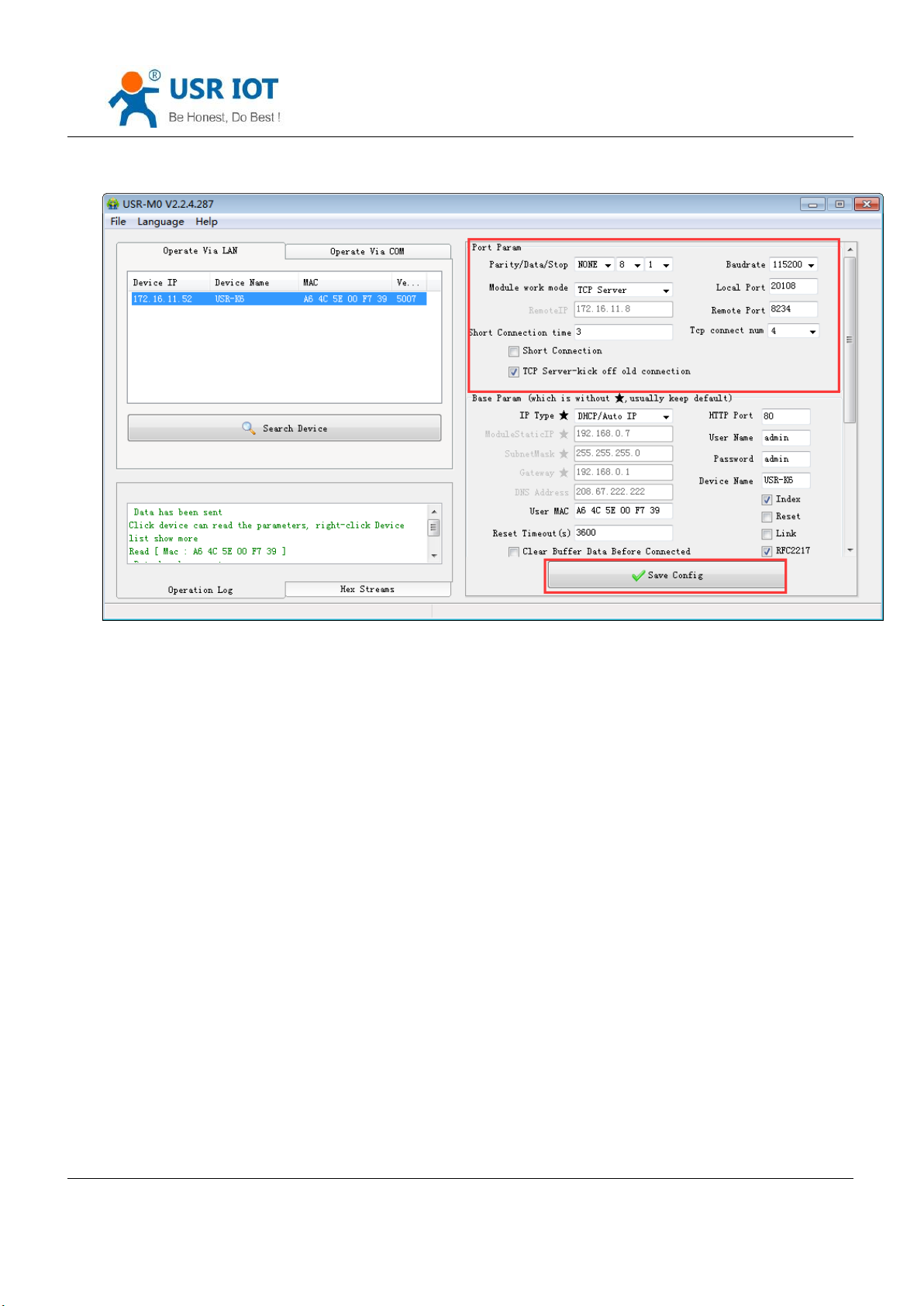
3. Serial port parameters
Jinan USR IOT Technology Limited 60 / 107 [email protected]
Page 61
USR-K6 User Manual www.usriot.com
Diagram 5.1.1-4 Serial Port Parameters
Serial baud rate: the baud rate for serial port communication, both standard and customize baud rate are ok.
Parity/data/stop: serial port parameters
Work mode: TCP Server /TCP Client/Httpd Client/UDP Client/UDP Server
Remote IP: when K6 works in TCP client, UDP client and HTTPD client mode as a client, the IP or domain name of
the server that it connected.
Similar RFC2217: used if need to change the serial port in transport. Use with V-COM or you can reference the
software manual.
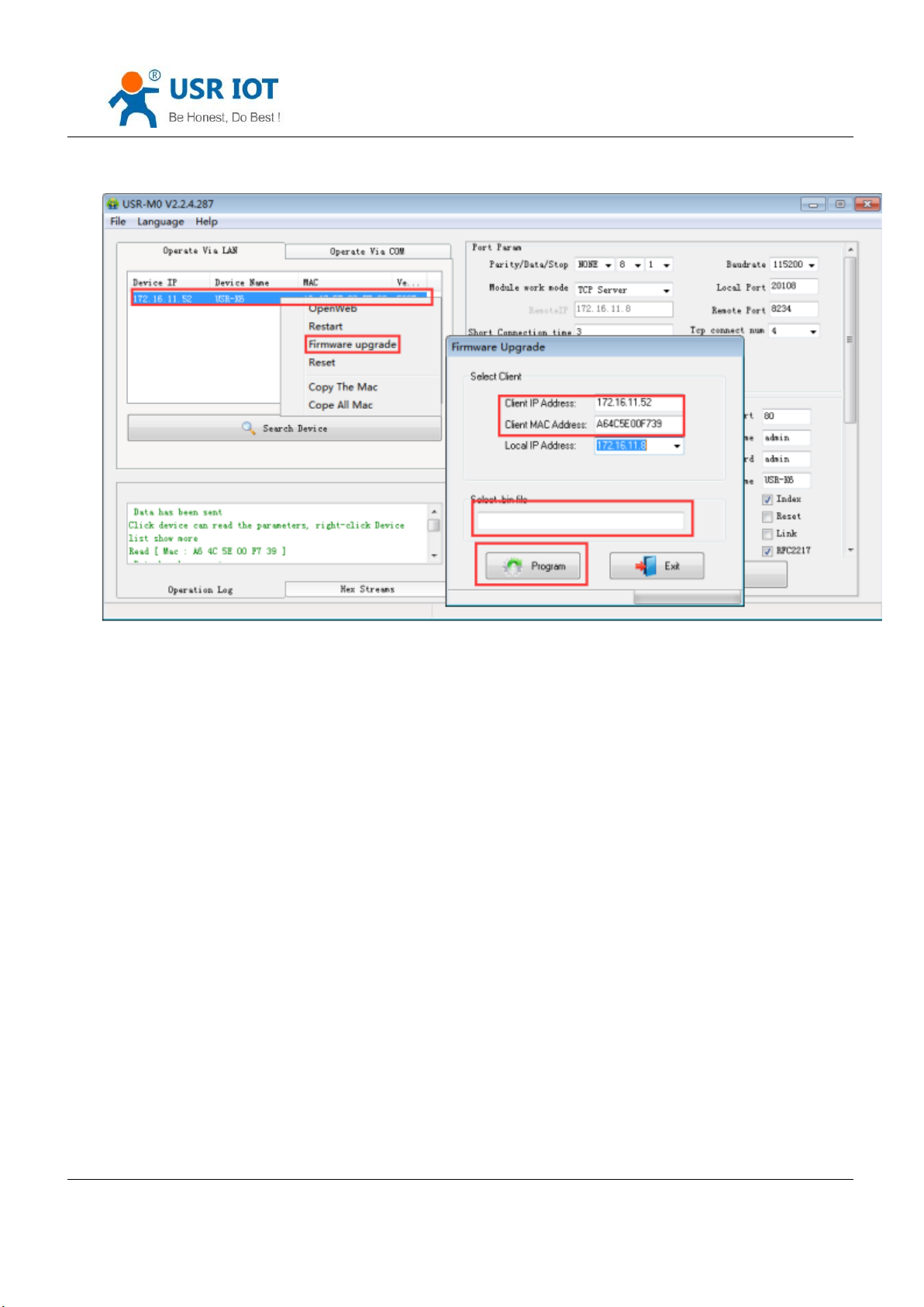
4. Firmware Upgrade
If the module firmware need to upgrade to the high vision,user can consult with sales to get the upgraded
firmware and click the device, upgrade the vision. When you upgrade it,connect directly the device and PC and notice
that PC upgrading module is forbidden.
Select the device and right click, then upgrade the firmware.
Jinan USR IOT Technology Limited 61 / 107 [email protected]
Page 62
USR-K6 User Manual www.usriot.com
Diagram 5.1.1-5 Firmware Upgrade
5.1.2. Setting Protocol Setting the Parameters
We set special protocol on the net setting. To be convenient to set across the net, all communication protocol
adopted UDP mode, the lower is in front. When setting, make sure the remote port is 1500 for UDP communication,
the local port is random and all the communication protocol using UDP.
1. Net setting parameters steps
① Built socket:
Build a UDP socket, remote IP :255.255.255.255, remote port:1500, lower is in front.
② Setting command steps
Send searching order on the internet.
K6 return the IP address, MAC, device name and version.
Jinan USR IOT Technology Limited 62 / 107 [email protected]
Page 63

USR-K6 User Manual www.usriot.com
function
Package
head
length
(order~ parameters bit)
order
MAC
(6 bits)
Username and
password (12 bits)
parameters
Parity
(sum)
search
FF
01
01 - - - 02
restart
FF
xx
02
[MAC]
[usrname]
[password]
-
xx
Read setting
FF
xx
03
[MAC]
[usrname]
[password]
-
xx
basic setting
FF
xx
05
[MAC]
[usrname]
[password]
basic
parameters
xx
serial port 0
setting
FF
xx
06
[MAC]
[usrname]
[password]
serial port
parameters
xx
Net port read the parameter that K6 returned.
Combine the MAC address the username, password and the parameter that need setting to be a setting
command.
Send setting command and restart.
K6 return setting right.
Restart command.
The return command of K6 right (wrong).
2. Net setting command content
Net setting protocol command means upper send command via net to modify the protocol command of the
module or the server.
① Command query
Jinan USR IOT Technology Limited 63 / 107 [email protected]
Page 64

USR-K6 User Manual www.usriot.com
reset
FF
xx
0b
[MAC]
[usrname]
[password]
-
xx
USR-cloud
FF
xx
0c
[MAC]
[usrname]
[password]
serial port
parameters
xx
Heartbeat/
registration
package
setting
FF
xx
21
[MAC]
[usrname]
[password]
serial port
parameters
xx
Httpd URL
setting
FF
xx
22
[MAC]
[usrname]
[password]
Httpd URL
xx
Httpd
package
head setting
FF
xx
23
[MAC]
[usrname]
[password]
Httpd
package
head
xx
Extend
setting
- - - - - - -
the parity is sum parity: begin at the length add to the first digit of the parity. The sum is the value to parity, and
reserve the lower bits.
6E + 00, from 4th to 9th is the address of the MAC, the last 12 bits in front add the parity is the user name and
password. These are 6 bits, add 0 if less than 6 bits.
Jinan USR IOT Technology Limited 64 / 107 [email protected]
Form 5.1.2-1 Command Query
To make sure the accuracy of the command, we setting the algorithm and check of sending command in protoco:
② Search command
Search command is: FF 01 01 02, parity sum 02 = 01 + 01.
③ Restart command
Send (22 bits ) FF 13 02 D8 B0 4C 46 35 CA 61 64 6D 69 6E 00 61 64 6D 69 6E 00 40, parity sum: 40 = 13 + 02 + ... +
Note: the last one of the username and password is 0,below are same.
Page 65

USR-K6 User Manual www.usriot.com
Name
bits
E.g.
Instr
Uc Sequence Num
1
00
reserve package head
Uc CRC
1
00
reserve package head
Uc Version
1
00
reserve package head
Uc Flags
1
C0
8th is 0: DHCP: 1: static IP
6th is 0: long connection: 1: short connection
5th is 0: not clear cache: 1: clear cache
Us Location URL Port
2
00 00
Not enable,reserve the protocol
Us HTTP Server Port
2
50 00
HTTP server port
Uc User Flag
1
00
Not enable,reserve the protocol
Ul Static IP
4
07 00 A8 C0
Static IP
Ul Gateway IP
4
C9 00 A8 C0
Gateway
Ul Subnet Mask
4
00 FF FF FF
Subnet Mask
④ Read setting command
Send (22bits): FF 13 03 D8 B0 4C 46 35 CA 61 64 6D 69 6E 00 61 64 6D 69 6E 00 41, parity sum: 41 = 13 + 03 + ... +
6E + 00, from 4th to 9th is the address of the MAC, the last 12 bits in front add the parity is the user name and
password. These are 6 bits, add 0 if less than 6 bits.
⑤ Basic parameter setting command
Basic setting command including 67 basic parameters. Setting For better Settings, here are some examples:
sending: FF 56 05 D8 B0 4C 46 35 CA 61 64 6D 69 6E 00 61 64 6D 69 6E 00 95 63 03 00 00 00 50 00 00 07 00 A8 C0 01
00 A8 C0 00 FF FF FF 55 53 52 2D 4B 32 00 00 00 00 00 00 00 00 00 00 61 64 6D 69 6E 00 61 64 6D 69 6E 00 00 01 00
E0 D8 B0 4C 46 35 CA 00 00 00 00 03 00 00 00 59, parity bits is still parity sum algorithm: 59 = 56 + 05 + D8+ ... + 03:
from 4th to 9th is the address of the MAC, from 10th to the 22th is the username + password, the latter bits is fixed
length basic setting parameters. The last bit is the parity sum.
Jinan USR IOT Technology Limited 65 / 107 [email protected]
Page 66

USR-K6 User Manual www.usriot.com
Uc Mod Name
14
55 53 52 2D 4B 32 00
00 00 00 00 00 00 00
Mod Name
Protocol reserve
2
00 00
0
username
6
61 64 6D 69 6E 00
username
password
6
61 64 6D 69 6E 00
password
Uc Net Send Time
1
00
Not enable,reserve the protocol
Ui Id
2
01 00
device ID
Uc Id Type
1
00
8th is 1: RFC2217 on, 0: RFC2217 off:
7th is 1: index on: 0: index off:
6th is 1: link light on: 0: link light off:
5th is 1: reset on: 0: reset off
2th is 1: send data carry ID: 0: off
1th is 1: build connection send ID: 0: off
mac_add rs
6
D8 B0 4C 11 22 33
Device MAC address
DNS Gateway IP
4
01 00 A8 C0
DNS server address
TC_sh_time
1
03
The time for short connection
Uc Reserved
3
00 00 00
Not enable,reserve the protocol
⑥ Serial port parameters command
There are 63 bits to setting net port and serial port parameters, so this command is of high value. Here is a
example to show how to use:(sending 63 bits): FF 52 0 4C 46 35 CA 61 64 6D 69 6E 00 61 64 6D 69 6E 00 00 C2 01 00
08 01 01 01 00 00 00 00 8C 4E 2A06 D8 B 20 31 39 32 2E 31 36 38 2E 31 2E 31 33 33 00 00 00 00 00 00 00 00 00 00 00
00 00 00 00 00 00 85 01 A8 C0 01 03 00 04 10 0E 00 00 00 00 00 00 00 16, parity bits algorithm: 16 = 52 + 06 + ... + 00;
Jinan USR IOT Technology Limited 66 / 107 [email protected]
Form 5.1.2-2 Basic Parameter Web Setting
Page 67

USR-K6 User Manual www.usriot.com
name
bits
E.g.
Instr
Ul Baud Rate
4
00 C2 01 00
Serial port baud rate
Uc Data Size
1
08
Serial port data bits(0X05/0x06/0x07/0x08)
Uc Parity
1
01
Serial port parity
1: no, 2: odd, 3: even, 4: mark, 5: space
Uc Stop Bits
1
01
Serial port stop(0x01/0x02)
Uc Flow Control
1
00
Not enable,reserve the protocol
Ul Telnet Timeout
4
00 00 00 00
Not enable,reserve the protocol
Us Telnet Local Port
2
8C 4E
Local port
Us Telnet Remote Port
2
2a 20
Remote port
Ui Telnet URL
30
31 39 32 2E 31 36 38 2E
30 2E 31 00 00 00 00 00
00 00 00 00 00 00 00 00
00 00 00 00 00 00
Send the IP address or domain name in ASCII code,
e.g:92.168.0.201 (remote IP setting)
Ul Telnet IP Addr
4
00 00 00 00
No effect, set randomly
Uc Flags
1
00
5th is 0: disable USR-cloud: 1: enable USR-cloud:
6th is 0: TCP Server mode do not click the order one.
1: TCP Server mode click the order one.
7th is 0: close MAC registration package:
1: MAC do as registration package:
from 4th to 9
th
is the address of the MAC, from 10
1bits and parity.
th
to the 22th is the username + password,then is the port parameters +
Jinan USR IOT Technology Limited 67 / 107 [email protected]
Page 68

USR-K6 User Manual www.usriot.com
Uc Work Mode
1
01
Work mode:
0: UDP, 1: TCP Client, 2: UDP Server, 3: TCP Server, 4:
HTTPD Client
HTP uc Flags
1
00
0: HTTPD GET: 1: HTTPD POST
tc_number
1
04
The number of client that TCP Server connected
Timeout_restart
2
00 00
Restart timeout
cos_register_flag
1
00
Customize registration package
Uc Time Count
1
91
Please withe the read fetch value as it is
Ui Pack Len
2
00 00
Not enable,reserve the protocol
Uc Reserved
3
00 00 00
Not enable,reserve the protocol
Form 5.1.2-3 Serial Port Parameters
⑦ Restore to factory command
Send: FF 13 0B D8 B0 4C 46 35 CA 61 64 6D 69 6E 00 61 64 6D 69 6E 00 49: parity sum: 49 = 13 + 0b+ ... + 6E + 00:
from 4th to 9th is the address of the MAC, from 10th to the 21th is the username + password, These are 6 bits, add 0 if
less than 6 bits.
⑧ USR-cloud command
Send: FF 13 0c 00 71 77 7c 42 2F 61 64 6d 69 6e 00 61 64 6d 69 6e 00 00 00 00 00 00 00 00 00 00 00 00 00 00 00
00 00 00 00 00 00 00 00 00 00 00 00 00 00 08;
Parity sum: 07 = 13 + 0c + ... + 6E + 00+...+00:
From 4th to 9th is the address of the MAC, from 10th to the 21th is the username + password, These are 6 bits, add 0
if less than 6 bits. The later are the USR-cloud ID and password of device, the last one is parity.
⑨ Heartbeat/registration package command
Send: FF 68 21 D8 B0 4C 46 35 CA 61 64 6D 69 6E 00 61 64 6D 69 6E 00 04 1E 00 0A 0A 77 77 77 2E 75 73 72 2E
63 6E 00 00 00 00 00 00 00 00 00 00 00 00 00 00 00 00 00 00 00 00 00 00 00 00 00 00 00 00 00 00 77 77 77 2E 75 73
72 2E 63 6E 00 00 00 00 00 00 00 00 00 00 00 00 00 00 00 00 00 00 00 00 00 00 00 00 00 00 00 00 00 00 C2:
Jinan USR IOT Technology Limited 68 / 107 [email protected]
Page 69

USR-K6 User Manual www.usriot.com
Name
Bits
E.g.
Instr
H_R_uc Flags
1
00
Heartbeat registration package mark:
1th is 1: send heartbeat package to net port
2th is 1: send heartbeat package to serial port;
3th is 1: connected sending to registration package:
4th is 1: data carry registration package:
5th is 1: Httpd information drop package head
6th is 1: serial port setting parameters function on
7th is 1: heartbeat package hexadecimal input
8th is 1: registration package hexadecimal input
heart_times
2
00 1e
Heartbeat time
heart_len
1
00
Length of heartbeat package
register_len
1
00
Length registration package
heartbeat
40
00 00 00 00 00 00 00 00 00 00 00 00 00 00
00 00 00 00 00 00 00 00 00 00 00 00 00 00
00 00 00 00 00 00 00 00 00 00 00 00
Heartbeat package content
register_s
40
00 00 00 00 00 00 00 00 00 00 00 00 00 00
00 00 00 00 00 00 00 00 00 00 00 00 00 00
00 00 00 00 00 00 00 00 00 00 00 00
Registration package content
Parity sum: C2 = 68 + 21 + ... + 6E + 00+...+00:
From 4th to 9th is the address of the MAC, from 10th to the 21th is the username + password. These are 6 bits, add 0
if less than 6 bits. The later are sending direct of heartbeat package and registration package, heartbeat time0, length of
the heartbeat, length of registration package, heartbeat package, registration package, heartbeat package and
registration package. These are 40 bits, add 0 if less than 40. The last one is parity.
Form 5.1.2-4 Heartbeat Registration Package Net Setting
Jinan USR IOT Technology Limited 69 / 107 [email protected]
Page 70
USR-K6 User Manual www.usriot.com
Name
Bits
E.g.
Instr
url_len
1
00
Length of Httpd URL
httpd_send_url
100
00
Httpd Client URL
name
Bits
E.g.
instr
head_lenn
1
00
Length of Httpd Client
httpd_send_btemp
200
00
Httpd Client package head
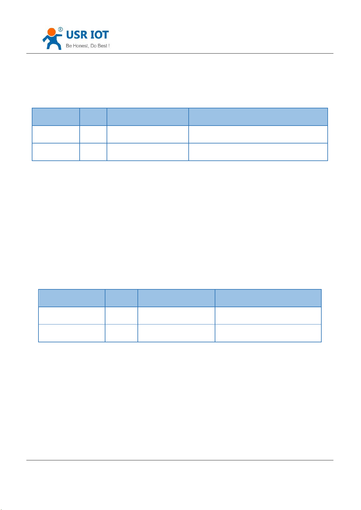
⑩ HTTPD client header setting
Setting URL protocol
Form 5.1.2-5 URL Protocol
Send : FF 78 22 D8 B0 4C 44 85 64 61 64 6D 69 6E 00 61 64 6D 69 6E 00 07 2F 31 2E 70 68 70 3F 00 00 00 00 00 00
00 00 00 00 00 00 00 00 00 00 00 00 00 00 00 00 00 00 00 00 00 00 00 00 00 00 00 00 00 00 00 00 00 00 00 00 00 00
00 00 00 00 00 00 00 00 00 00 00 00 00 00 00 00 00 00 00 00 00 00 00 00 00 00 00 00 00 00 00 00 00 00 00 00 00 00
00 00 00 00 00 00 00 00 00 00 00 C9;
Parity sum: C9 = 78 + 22 + ... + 3F + 00+...+00:
From 4th to 9th is the MAC address of the module, the later 12 is username and password, these are 6 bits add 0 if
less than 6, the last one is parity.
Setting package setting
Form 5.1.2-6 Package setting
Send: FF DC 23 D8 B0 4C 44 85 64 61 64 6D 69 6E 00 61 64 6D 69 6E 00 07 2F 31 2E 70 68 70 3F 00 00 00 00 00 00
00 00 00 00 00 00 00 00 00 00 00 00 00 00 00 00 00 00 00 00 00 00 00 00 00 00 00 00 00 00 00 00 00 00 00 00 00 00
00 00 00 00 00 00 00 00 00 00 00 00 00 00 00 00 00 00 00 00 00 00 00 00 00 00 00 00 00 00 00 00 00 00 00 00 00 00
00 00 00 00 00 00 00 00 00 00 00 2A 55 73 65 72 5F 41 67 65 6E 74 3A 20 4D 6F 7A 69 6C 6C 61 2F 34 2E 30 0D 0A 43
6F 6E 6E 65 63 74 69 6F 6E 3A 20 63 6C 6F 73 65 00 00 00 00 00 00 00 00 00 00 00 00 00 00 00 00 00 00 00 00 00 00
00 00 00 00 00 00 00 00 00 00 00 00 00 00 00 00 00 00 00 00 00 00 00 00 00 00 00 00 00 00 00 00 00 00 00 CF:
Parity sum: CF = DC + 23 + ... + 65 + 00+...+00:
Jinan USR IOT Technology Limited 70 / 107 [email protected]
Page 71

USR-K6 User Manual www.usriot.com
name
bits
E.g.
Instr
TAG_STATUS
0
FF
fixed number
Packet_length
1
24
fixed number
CMD_DISCOVER_TARGET
2
01
fixed number
Board_type
3
00
fixed number
Board_ID
4
00
fixed number
Client_IP_address
5~8
C0 A8 00 07
device IP( higher in front )
MAC_address
9~14
AC CF 23 20 FE 3D
device MAC( higher in front )
Firmware_version
15~18
01 00 00
Firmware version
Application_title
19~34
55 53 52 2D 4B 32
00 00 00 00 00 00
00 00 00 00
device name
checksum
35
F0
(this value can be ignore)
Check sum initial value is 0x00, reduce every bits of
TAG_STATUS in order,till the last bit, and the result is
th
From 4
th
to 9
is the MAC address of the module, the later 12 is username and password, these are 6 bits add 0 if
less than 6, the last one is parity.
3. Net return the command
① The result of search command return
The result of search command return( 36 bits): FF 24 01 00 00 c0 a8 00 07 00 71 77 7c 42 2F 01 0c 00 00 55 53 52
2d 4b 32 00 00 00 00 00 00 00 00 00 00 F2,
Parity way is reduce parity sum, the initial value is 0x00, reduce every bits in order, algorithm is as fellow: F2 = 00 FF - 24 - 01 - 00 - 4B - ... - 32 – 00-…-00.
Jinan USR IOT Technology Limited 71 / 107 [email protected]
Page 72
USR-K6 User Manual www.usriot.com
checksum.
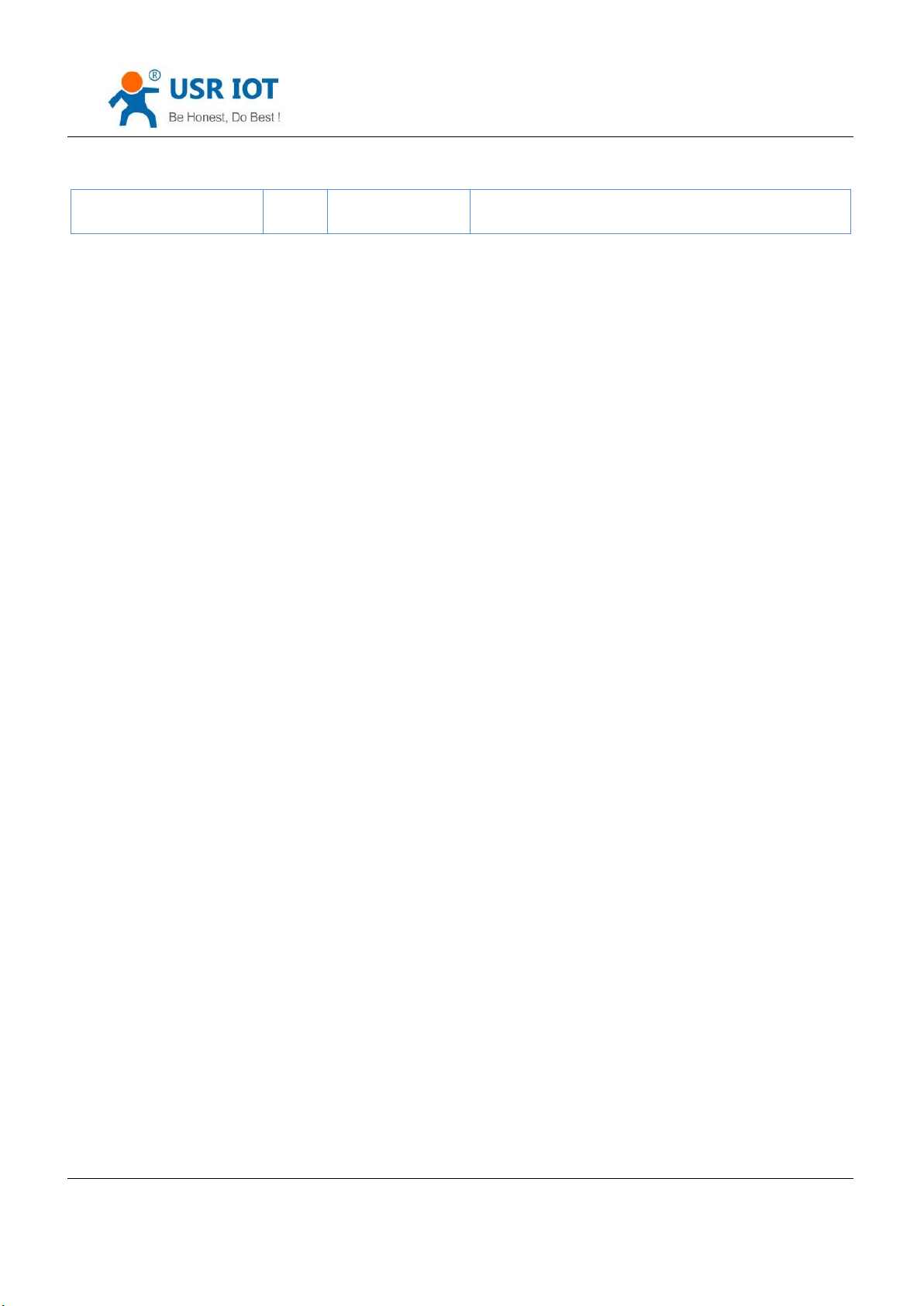
Form 5.1.2-7 Return Command
② Restart command return result
Respond (4 bits): FF 01 02 4B if the password right 4B = 'K'
FF 01 02 50 username password wrong 50 ='P'
③ Read order command return result
The return are all the parameters, total 576, no parity and protocol, return parameters directly. Method of reading
reference “basic parameters chart” “serial parameters chart”and USR-cloud function, heartbeat registration package
function and Httpd Client package head setting. Return divide into 4 package, including 130 bits, 50bits, 85 bits and 302
bits.
Respond e.g.: 95 63 03 00 00 00 50 00 00 07 00 A8 C0 01 00 A8 C0 00 FF FF FF 55 53 52 2D 54 43 50 32 33 32 2D
33 31 30 00 00 61 64 6D 69 6E 00 61 64 6D 69 6E 00 00 01 00 A4 AC CF 23 20 FE 10 00 00 00 00 00 00 00 00 80 25 00
00 08 01 01 01 00 00 00 00 8C 4E 2A 20 31 39 32 2E 31 36 38 2E 31 2E 31 33 33 00 00 00 00 00 00 00 00 00 00 00 00
00 00 00 00 00 85 01 A8 C0 00 01 00 00 00 00 00 00 00 00 00 00 00:
00 00 00 00 00 00 00 00 00 00 00 00 00 00 00 00 00 00 00 00 00 00 00 00 00 00 00 00 00 00 00 00 00 00 00 00 00
00 00 00 00 00 00 00 00 00 00 00 00 00
00 30 00 00 00 00 00 00 00 00 00 00 00 00 00 00 00 00 00 00 00 00 00 00 00 00 00 00 00 00 00 00 00 00 00 00 00
00 00 00 00 00 00 00 00 00 00 00 00 00 00 00 00 00 00 00 00 00 00 00 00 00 00 00 00 00 00 00 00 00 00 00 00 00 00
00 00 00 00 00 00:
07 2F 31 2E 70 68 70 3F 00 00 00 00 00 00 00 00 00 00 00 00 00 00 00 00 00 00 00 00 00 00 00 00 00 00 00 00 00
00 00 00 00 00 00 00 00 00 00 00 00 00 00 00 00 00 00 00 00 00 00 00 00 00 00 00 00 00 00 00 00 00 00 00 00 00 00
00 00 00 00 00 00 00 00 00 00 00 00 00 00 00 00 00 00 00 00 00 00 00 00 00 00 2A 55 73 65 72 5F 41 67 65 6E 74 3A
20 4D 6F 7A 69 6C 6C 61 2F 34 2E 30 0D 0A 43 6F 6E 6E 65 63 74 69 6F 6E 3A 20 63 6C 6F 73 65 00 00 00 00 00 00 00
00 00 00 00 00 00 00 00 00 00 00 00 00 00 00 00 00 00 00 00 00 00 00 00 00 00 00 00 00 00 00 00 00 00 00 00 00 00
00 00 00 00 00 00 00 00 00 00 00 00 00 00 00 00 00 00 00 00 00 00 00 00 00 00 00 00 00 00 00 00 00 00 00 00 00 00
00 00 00 00 00 00 00 00 00 00 00 00 00 00 00 00 00 00 00 00 00 00 00 00 00 00 00 00 00 00 00 00 00 00 00 00 00 00
00 00 00 00 00 00 00 00 00 00 00 00 00 00 00 00 00 00 00 00 00 00 00 00 00 00 00 00 00 00 00 00 00 00 00 00 00
password fault: FF 01 03 50, the return data have no parity.
Jinan USR IOT Technology Limited 72 / 107 [email protected]
Page 73

USR-K6 User Manual www.usriot.com
④ Basic parameters setting command return result
Setting correct return: FF 01 05 4B if the password right 4B = 'K':
FF 01 05 50 username password wrong 50 ='P'.
⑤ Serial parameters setting command return result
Setting correct return: FF 01 06 4B if the password right 4B = 'K':
FF 01 06 50 username password wrong 50 ='P'.
⑥ USR-cloud parameters setting command return result
Setting correct return: FF 01 06 4B if the password right 4B = 'K':
FF 01 06 50 username password wrong 50 ='P'.
⑦ Heartbeat registration package parameters setting command return result
Setting correct return: FF 01 06 4B if the password right 4B = 'K':
FF 01 06 50 username password wrong 50 ='P'.
⑧ Httpd URL setting command return result
Setting correct return: FF 01 22 4B if the password right 4B = 'K':
FF 01 22 50 username password wrong 50 ='P'.
⑨ Httpd package head command return result
Setting correct return: FF 01 23 4B if the password right 4B = 'K':
FF 01 23 50 username password wrong 50 ='P'.
⑩ Other return
Parity and return: return 'E' + right value:
Correct perform: FF 01 CMD‘K’:
Username password wrong return: FF 01 CMD‘P‘:
Jinan USR IOT Technology Limited 73 / 107 [email protected]
Page 74
USR-K6 User Manual www.usriot.com
Other wrong return: FF 01 CMD‘E’.
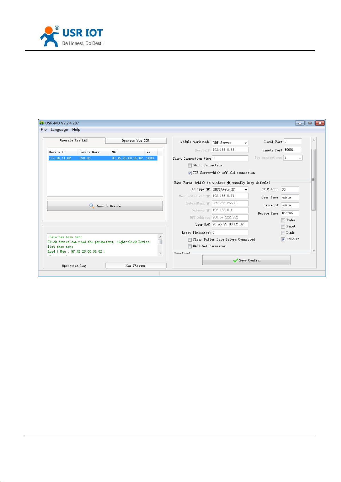
4. Message monitoring method
If you want to get some real message using the way as below:the tool is setting softwareUSR-M0:
Diagram 5.1.2-1 Catch the Message
5.2. Webpage Setting Parameters
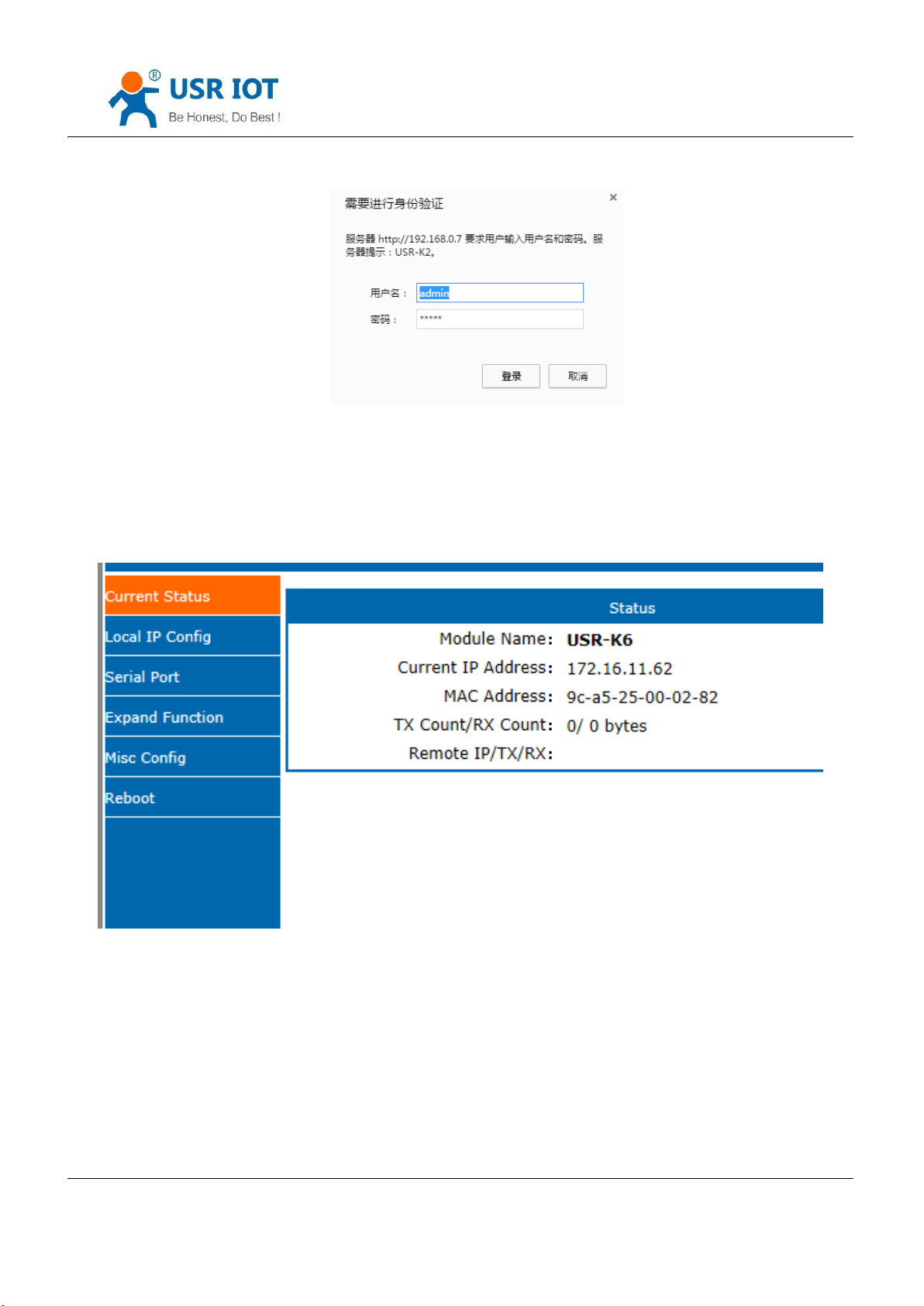
Open the browser and enter the IP of K6, default is (192.168.0.7). filled the user name: admin and password:
admin, then login and you can enter the login page.
Jinan USR IOT Technology Limited 74 / 107 [email protected]
Page 75
USR-K6 User Manual www.usriot.com
Diagram 5.2-1 Username and Password
Click the English or Chinese on the right upper to switch the language.
1. Current status
Diagram 5.2-2 Current Status
This page show song information of the K6
Module name
Current IP address
MAC address
Jinan USR IOT Technology Limited 75 / 107 [email protected]
Page 76
USR-K6 User Manual www.usriot.com
IP of the connected device and the sent of receive number of the data.
Total number of connection receive or send
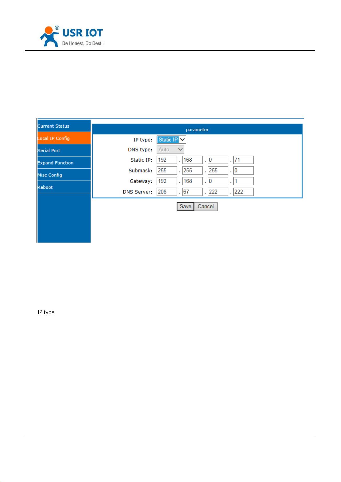
2. Local IP Configure
Diagram 5.2-3 Local IP Configure
Modify the parameters and save,then modify the parameter in next page. If the parameter need not to
modify ,click the restart and work.
Static IP
Subnet masks
Gateway
DNS server
3. Serial port
Jinan USR IOT Technology Limited 76 / 107 [email protected]
Page 77
USR-K6 User Manual www.usriot.com
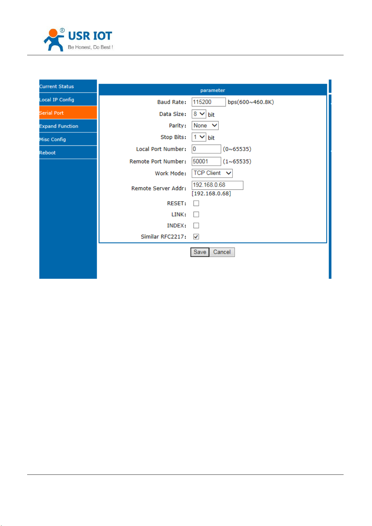
Baud rate
Data
Parity
Stop
Local port
Remote port
Work mode
Remote server address
Special functions
Diagram 5.2-4 Serial Port
Jinan USR IOT Technology Limited 77 / 107 [email protected]
Page 78
4. Expand Function
USR-K6 User Manual www.usriot.com
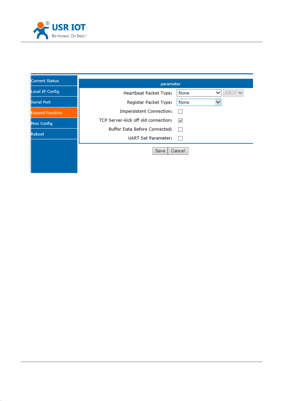
Diagram 5.2-5 Expand Function
USR-cloud number and password
Customize heartbeat package: open with webpage, content customize and the max number is 40bite
Customize registration package: open with webpage, content customize and the max number is 40bite, the
method to use can be customize
Short connection: enable under the TCP client and the time can be customize
Clear buffer data: whether or not
TCP server-kick off old connection
Serial port parameter setting: open with webpage and setting with serial port parameter
5. Miss configure
Jinan USR IOT Technology Limited 78 / 107 [email protected]
Page 79
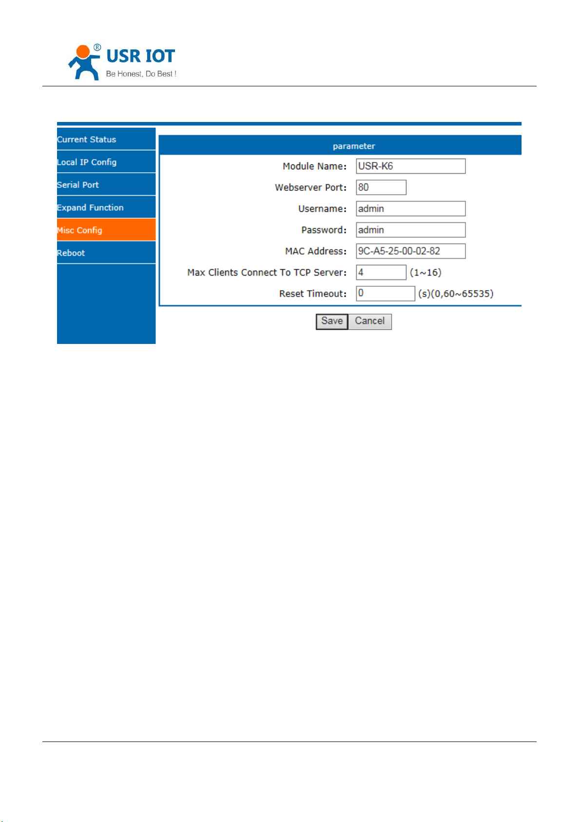
USR-K6 User Manual www.usriot.com
Module name
Webserver port
Username
Password
MAC address
Max client connected to TCP server
Reset timeout
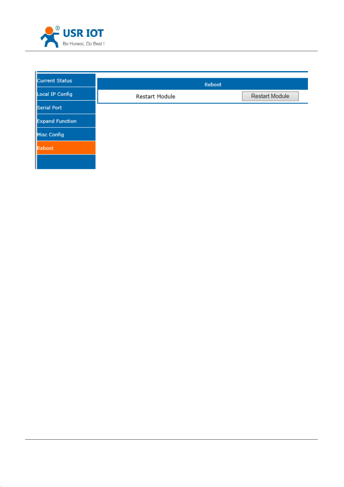
6. Reboot
Diagram 5.2-6 Miss configure
Jinan USR IOT Technology Limited 79 / 107 [email protected]
Page 80
USR-K6 User Manual www.usriot.com
Save all the data and restart, then the K6 work.
Diagram 5.2-7 Reboot
5.3. AT Command
AT command is used for controlling module. You can use AT command to configure and query the settings. Later
we will interpret the type in detail.
5.3.1. AT Command Overview
AT+ command is the command collection that perform the command transport using UART and module under the
order mode. Later we will interpret the type in detail.
Powered successfully, we can setting the module with UART.
The default UART port parameters of the module are: baud rate1152000, no parity, data 8 and stop 1.
Instr
AT command test tools.UART interface recommand to use secureCRT software tool or USR pro APP. Below are
using the secureCRT with UART to perform.
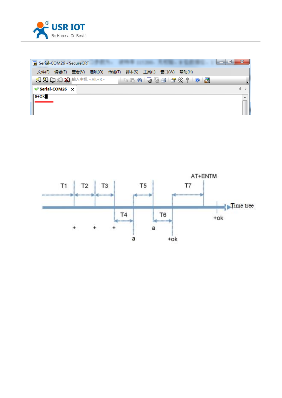
From transparent transport to order mode need two step as below:
Fill “+++”in the UART. After the module receive the “++++”,it will send a “a” to confirm;
Fill the confirming “a” in the UART, after the module receive and send “+ok”, enter the command mode.
Jinan USR IOT Technology Limited 80 / 107 [email protected]
Page 81
USR-K6 User Manual www.usriot.com
Diagram 5.3.1-1 Enter the AT Command
Instr: if no feedback after fill “++++”and “a”, as the above.
Fill “+++”and “a” need to achieve in the time to reduce the chance of entering command mode while working
normally accidentally. Detail requirement are as fellows.
Diagram 5.3.1-2 Time Tree
Time requirement:
T1>the interval of serial port package
T2<300ms
T3<300ms
T5<3s
The order change into temporary command mode from transparent transport mode:
Jinan USR IOT Technology Limited 81 / 107 [email protected]
Page 82
USR-K6 User Manual www.usriot.com
Error code
Instr
-1
Invalid format
-2
Invalid order
-3
Invalid operator
-4
Invalid parameter
-5
Not allow
Num
command
Instr
1 E Enable/disable the echo function
2 Z restart module
3
VER
Query the vision
1. Serial mode device send “+++”to module continuously. The module receive and send “a” back. Before sending“+++”is
the packaging time and can not send any data.
2. After receive “a” feedback a “a”in 3s.
3. After the module receive “a, send “ok”to the device, and enter “AT”command
4. After the device receive “+ok” and know the module enter the AT command mode, then send AT command.
The order change into net transparent transport from AT command mode:
1.Serial device send “AT+ENTM”to module.
2.After the module receive the command, feedback “+ok”, then back to the previous working mode.
5.3.2. AT Command Error Code
5.3.3. AT Command
Jinan USR IOT Technology Limited 82 / 107 [email protected]
Form 5.3.2-1 Error Code List
Page 83
USR-K6 User Manual www.usriot.com
4
ENTM
Exit AT command mode
5
RELD
Reset default settings
6
MAC
Query module MAC address
7
USERMAC
Setting customize MAC
8
WEBU
Setting/ query username and password
9
WANN
Setting/ query WAN port parameters
10
DNS
Setting/ query DNS server address
11
WEBPORT
Setting/ query webpage port
12
UART
Setting/ query serial parameters
13
SOCK
Setting/ query SOCK parameters
14
TCPSE
Setting/ query whether kick off order connection
15
SOCKLK
Query TCP connect status
16
SOCKPORT
Setting/ query local port number
17
RECEN
Setting/ query RFC2217 enable
18
PDTIME
Query the product time
Registration package function
19
REGEN
Setting/ query registration package mechanism
20
REGTCP
Setting/ query registration package perform mechanism
21
REGCLOUD
Setting/ query USR-cloud username and password
22
REGUSR
Setting/ query the content of registration package that customized
Httpd client function
Jinan USR IOT Technology Limited 83 / 107 [email protected]
Page 84
USR-K6 User Manual www.usriot.com
23
HTPTP
Setting/ query in httpd client mode, the asking way of the http
24
HTPURL
Setting/ query the URL in httpd client mode
25
HTPHEAD
Setting/ query the package head in httpd client
26
HTPCHD
Setting/ query HTP remove the package head
Heartbeat package
27
HEARTEN
Setting/ query heartbeat package enable
28
HEARTTP
Setting/ query method of the heartbeat package send
29
HEARTTM
Setting/ query the heartbeat package time
30
HEARTDT
Setting/ query customize heartbeat package
Expand function command
31
SCSLINK
Setting/ query the indicating function of the status of socket connection
32
CLIENTRST
Setting/ query the TCP client mode reset function enable/disable
33
INDEXEN
Setting/ query index function
34
SOCKSL
Setting/ query short connection function
35
SHORTO
Setting/ query short connection time
36
UARTCLBUF
Setting/ query clear serial port cache before module build connection function
enable/disable
37
RSTIM
Setting/ query timeout reset time
38
MAXSK
Setting/ query maximum client connections in TCP server mode
39
MID
Setting/ query module name
40 H Query help message
(V4017 supporting command)
Jinan USR IOT Technology Limited 84 / 107 [email protected]
Page 85
USR-K6 User Manual www.usriot.com
41
AT+CFGTF
Save the current parameters as the default parameters
42
AT+PING
Ping automatically
Form 5.3.3-1 AT Command
5.3.4. AT Command Details
1. AT+E
Function: query/ setting module echo of the AT command setting
Format: query:
A+E<CR>
<CR><LF>+OK=< on/off ><CR><LF>
setting:
A+E=< on/off ><CR>
<CR><LF>+OK<CR><LF>
Parameters: ON: enable the echo, echo the command entered by the AT command.
OFF: under AT command mode, the entered command do not echo.
E.g.: AT+E=0N
2. AT+Z
Function: restart module
Format: setting:
AT+Z<CR>
<CR><LF>+OK<CR><LF>
Parameters: none
<note>: after perform this command correctly, module restart and exit the AT command mode.
Jinan USR IOT Technology Limited 85 / 107 [email protected]
Page 86

USR-K6 User Manual www.usriot.com
3. AT+VER
Function: query module firmware version.
Format: query:
AT+VER<CR>
<CR><LF>+OK=< ver ><CR><LF>
Parameters: ver: query module firmware version.
4. AT+ENTM
Function: exit the AT command mode and enter the transparent transmission:
Format: setting:
AT+ENTM<CR>
<CR><LF>+OK<CR><LF>
Parameters: none
<note>: after perform this command correctly, module change into command mode from transparent transmission
mode.
5. AT+RELD
Function: module reset
Format: setting:
AT+RELD<CR>
<CR><LF>+OK<CR><LF>
parameters: none.
6. AT+MAC
Function: query module MAC
Format: query:
Jinan USR IOT Technology Limited 86 / 107 [email protected]
Page 87

USR-K6 User Manual www.usriot.com
AT+MAC<CR>
<CR><LF>+OK=< MAC ><CR><LF>
parameters: mac: MAC address of the module( e.g.00020K2050A )
7. AT+USERMAC
Function: setting module customize MAC
Format: setting:
AT+ USERMAC =< MAC ><CR>
<CR><LF>+OK<CR><LF>
Parameters: mac: MAC address of the module, the first byte should be even, e.g. 002233445566
E.g.: AT+USERMAC=002233445566
8. AT+WEBU
Function: setting /query module username and password
Format: query:
AT+WEBU<CR>
<CR><LF>+OK=< username,password ><CR><LF>
setting:
AT+WEBU=< username,password ><CR>
<CR><LF>+OK<CR><LF>
Parameters: username: username, support 5 bytes at longest and can not be none:
password: password, support 5 bytes at longest.
E.g.: AT+WEBU=admin,admin
9. AT+WANN
Jinan USR IOT Technology Limited 87 / 107 [email protected]
Page 88

USR-K6 User Manual www.usriot.com
Function: setting /query the IP of WAN( DHCP/STATIC ) that module access
Format: query:
AT+WANN<CR>
<CR><LF>+OK=< mode,address,mask,gateway ><CR><LF>
setting:
AT+WANN=< mode,address,mask,gateway ><CR>
<CR><LF>+OK<CR><LF>
Parameters: mode: web IP mode ( static/DHCP )
static: static IP
DHCP: dynamic IP( address,mask,gateway parameters ignore )
address: IP address
mask: subnet masks
gateway: gateway address
E.g.: AT+WANN=static,192.168.0.7,255.255.255.0,192.168.0.1
10. AT+DNS
Function: setting /query DNS server address:
Format: query:
AT+DNS<CR>
<CR><LF>+OK=< address ><CR><LF>
setting:
AT+DNS=< address ><CR>
<CR><LF>+OK<CR><LF>
Jinan USR IOT Technology Limited 88 / 107 [email protected]
Page 89

USR-K6 User Manual www.usriot.com
Parameters: address: DNS server address( default value is 208.67.222.222 ).
E.g.: AT+DNS=208.67.222.222
11. AT+WEBPORT
Function: setting /query webpage port
Format: query:
AT+WEBPORT<CR>
<CR><LF>+OK=< port ><CR><LF>
setting:
AT+WEBPORT=< port ><CR>
<CR><LF>+OK<CR><LF>
Parameters: port: module the port of the web server that built in of module. default 80:
E.g.: AT+WEBPORT=80
12. AT+UART
Function: setting /query UART interface parameters
Format: query:
AT+UART<CR>
<CR><LF>+OK=< baudrate,data_bits,stop_bit,parity,flowctrl ><CR><LF>
setting:
AT+UART=< baud rate,data_bits,stop_bit,parity,flowctrl ><CR><LF>
<CR><LF>+OK<CR><LF>
Parameters: baudrate: baud rate600~460800bps,can be customized .
data_bits: data 5、6、7、8
Jinan USR IOT Technology Limited 89 / 107 [email protected]
Page 90

USR-K6 User Manual www.usriot.com
stop_bits: stop 1、2
parity: parity
NONE( no parity )
EVEN(even parity )
ODD( odd parity )
MASK(1 parity)
SPACE( 0 parity )
Flowctrl: flow control( none flow control, can not setting , default setting to be the NFC )
NFC: none: hardware flow control
FCH: have hardware flow control
FCR: software flow control
E.g.: AT+UART=115200,8,1,NONE,NFC
13. AT+SOCK
Function: setting /query web protocol parameters format
Format: query:
AT+SOCK<CR>
<CR><LF>+OK=< protocol,IP,port ><CR><LF>
setting:
AT+SOCK=< protocol,IP,port ><CR>
<CR><LF>+OK<CR><LF>
Parameters:
Protocol: protocol type, including
Jinan USR IOT Technology Limited 90 / 107 [email protected]
Page 91

USR-K6 User Manual www.usriot.com
TCPS is TCP server
TCPC is TCP client
UDPS is UDP server
UDPC is UDP client
HTPC is Httpd Client
IP: when the module setting into “CLIENT”mode, the IP address and domain name of the remote server.
Port: local port under Server mode and remote port under Client mode,decimal number and less than
65535.
E.g.: AT+SOCK=TCPC,192.168.0.201,8234
14. AT+TCPSE
Function: module is TCP Server, the processing mechanism after the connection reaches the maximum number of
connections.
Format: query:
AT+TCPSE<CR>
<CR><LF>+OK=< status ><CR><LF>
setting:
AT+TCPSE=< status ><CR>
<CR><LF>+OK<CR><LF>
Parameters:
Status: setting status keep/kick
keep: after reach the maximum number of connection, do not receive new one.
kick: after reach the maximum number of connection, delete the order one and connect the new one.
E.g.: AT+TCPSE=keep
Jinan USR IOT Technology Limited 91 / 107 [email protected]
Page 92

USR-K6 User Manual www.usriot.com
15. AT+SOCKLK
Function: query whether the TCP has connected
Format: query:
AT+ SOCKLK<CR>
<CR><LF>+OK=< sta ><CR><LF>
Parameters:
Sta: built the TCP connection or not
Connect: TCP connected
Disconnect: TCP not connected
16. AT+SOCKPORT
Function: setting /query local socket port
Format: query:
AT+SOCKPORT<CR>
<CR><LF>+OK=< sta ><CR><LF>
setting:
AT+ SOCKPORT =< sta ><CR>
<CR><LF>+OK<CR><LF>
Parameters:
Sta: 0 is using port randomly. 1-65535 is using the local port of the socket.
E.g.: AT+SOCKPORT=20108:
17. AT+RFCEN
Function: enable/ disable RFC221 7function
Jinan USR IOT Technology Limited 92 / 107 [email protected]
Page 93

Format: query:
setting:
Parameters:
status:
ON: enable RFC2217function
USR-K6 User Manual www.usriot.com
AT+RFCEN<CR>
<CR><LF>+OK=< status ><CR><LF>
AT+RFCEN =< status ><CR>
<CR><LF>+OK<CR><LF>
OFF: disable RFC2217function
E.g.: AT+RFCEN=ON
18. AT+PDTIME
Function: query produce time
Format: query:
AT+PDTIME<CR>
<CR><LF>+OK=< time ><CR><LF>
Parameters:
time: produce time, e.g.: 2016-10-18 11:20:02
19. AT+REGEN
Function: setting query registration package mechanism
Format: query:
Jinan USR IOT Technology Limited 93 / 107 [email protected]
Page 94

setting:
Parameters:
USR-K6 User Manual www.usriot.com
AT+REGEN<CR>
<CR><LF>+OK=< status ><CR><LF>
AT+REGEN =< status ><CR>
<CR><LF>+OK<CR><LF>
status:
MAC: enable registration package mechanism, registration package is 6 bites MAC
Usr: customize registration package
Off: disable registration package mechanism
E.g.: AT+REGEN=MAC
20. AT+REGTCP
Function: setting query tcp client mode registration package perform mechanism
Format: query:
AT+REGTCP<CR>
<CR><LF>+OK=< status ><CR><LF>
setting:
AT+REGTCP =< status ><CR>
<CR><LF>+OK<CR><LF>
Parameters:
Status:
first: send a registration package when connected the server at first time
Jinan USR IOT Technology Limited 94 / 107 [email protected]
Page 95

USR-K6 User Manual www.usriot.com
every: add a registration package in front of the every data package sent to server.
all: send registration package when first connected to the server and add registration package in front of
the data package.
E.g.: AT+REGTCP=first
21. AT+REGCLOUD
Function: setting /query USR-cloud username and password
Format: query:
AT+REGCLOUD<CR>
<CR><LF>+OK=< name, password ><CR><LF>
setting:
AT+REGCLOUD=< name, password ><CR>
<CR><LF>+OK<CR><LF>
Parameters:
Status:
name: USR-cloud device port:
password: USR-cloud password .
E.g.: AT+REGCLOUD=0000000000000000000000, 00000000
22. AT+REGUSR
Function: setting query customize registration package content
Format: query:
AT+REGUSR<CR>
<CR><LF>+OK=< data ><CR><LF>
setting:
Jinan USR IOT Technology Limited 95 / 107 [email protected]
Page 96

USR-K6 User Manual www.usriot.com
AT+ REGUSR =< data ><CR>
<CR><LF>+OK<CR><LF>
Parameters:
data: ASCII code in 40 bytes
E.g.: AT+REGUSR=www.usr.cn
23. AT+HTPTP
Function: setting /query the asking way under HTTPD Client mode.
Format: query:
AT+HTPTP<CR>
<CR><LF>+OK=< status ><CR><LF>
setting:
AT+HTPTP =< status ><CR>
<CR><LF>+OK<CR><LF>
Parameters:
Status:
GET: is the http asking way
POST: is the http asking way
E.g.: AT+HTPTP=GET
24. AT+HTPURL
Function: setting /query Httpd 的 URL.
Format: query:
AT+HTPURL<CR>
Jinan USR IOT Technology Limited 96 / 107 [email protected]
Page 97

USR-K6 User Manual www.usriot.com
<CR><LF>+OK=< URL ><CR><LF>
setting:
AT+HTPURL =< URL ><CR>
<CR><LF>+OK<CR><LF>
Parameters:
URL: start with “/”, less than 99 bytes .
E.g.: AT+HTPURL=/2.php
25. AT+HTPHEAD
Function: setting /query Httpd Client customize package head message
Format: query:
AT+HTPHEAD<CR>
<CR><LF>+OK=< data ><CR><LF>
setting:
AT+ HTPHEAD =< data ><CR>
<CR><LF>+OK<CR><LF>
Parameters:
data: customize package message, less than 199 bytes. And using <<CRLF>> translating the characters in
stead of the enter.
E.g.: AT+HTPHEAD=Accept:text<<CRLF>>
26. AT+HTPCHD
Function: setting /query filter the package head of the return information of Http
Format: query:
AT+ HTPCHD <CR>
Jinan USR IOT Technology Limited 97 / 107 [email protected]
Page 98

<CR><LF>+OK=< sta ><CR><LF>
setting:
AT+ HTPCHD =< sta ><CR>
<CR><LF>+OK<CR><LF>
Parameters: Sta:
ON: enable
OFF: disable
E.g.: AT+HTPCHD=ON
27. AT+HEARTEN
USR-K6 User Manual www.usriot.com
Function: setting /query enable or not heartbeat package
Format: query:
AT+ HEARTEN <CR>
<CR><LF>+OK=< status ><CR><LF>
setting:
AT+ HEARTEN =< status ><CR>
<CR><LF>+OK<CR><LF>
Parameters:
Status:
ON:enable heartbeat package
Off: disable heartbeat package
E.g.: AT+HEARTEN=ON
28. AT+HEARTTP
Jinan USR IOT Technology Limited 98 / 107 [email protected]
Page 99

USR-K6 User Manual www.usriot.com
Function: setting /query heartbeat package send way
Format: query:
AT+ HEARTTP <CR>
<CR><LF>+OK=< type ><CR><LF>
setting:
AT+ HEARTTP =< type ><CR>
<CR><LF>+OK<CR><LF>
Parameters:
Status:
NET: send heartbeat package to server
COM: send heartbeat package to serial port
E.g.: AT+HEARTTP=NET
29. AT+HEARTTM
Function: setting /query time of heartbeat package
Format: query:
AT+ HEARTTM <CR>
<CR><LF>+OK=< time ><CR><LF>
setting:
AT+ HEARTTM =< time ><CR>
<CR><LF>+OK<CR><LF>
Parameters:
Time: heartbeat time ,default is 30s, range from 1 to 65535s.
Jinan USR IOT Technology Limited 99 / 107 [email protected]
Page 100

USR-K6 User Manual www.usriot.com
E.g.: AT+HEARTTM=30
30. AT+HEARTDT
Function: setting query customize heartbeat package content
Format: query:
AT+ HEARTDT <CR>
<CR><LF>+OK=< data ><CR><LF>
setting:
AT+ HEARTDT =< data ><CR>
<CR><LF>+OK<CR><LF>
Parameters:
data: less than 40 bytes ASCII code.
E.g.: AT+HEARTDT=www.usr.cn.
31. AT+ SCSLINK
Function: setting /query Socket connected status instructions function (connection status instructions pin change or not
according to the connection status)
Format: query:
AT+ SCSLINK <CR>
<CR><LF>+OK=< sta ><CR><LF>
setting:
AT+ SCSLINK =< sta ><CR>
<CR><LF>+OK<CR><LF>
Parameters: sta: status
ON: enable link function
Jinan USR IOT Technology Limited 100 / 107 [email protected]
 Loading...