

Page 1
USR-K2 Hardware Manual www.usriot.com
USR-K2 Hardware Manual
File version: 1.3.01
Jinan USR IOT Technology Limited 1 / 9 h.usriot.com
Page 2

USR-K2 Hardware Manual www.usriot.com
Content
USR-K2 Hardware Manual
1. Product Overview
1.1. Dimension
1.2. Pin Definition
1.3. Ethernet interface LED
2. Hardware Design
2.1. Typical Connection
2.2. Power Interface
2.3. UART Interface
3. Contact
4. Disclaimer
5. Update History
..........................................................................................................................................................................
....................................................................................................................................................................
......................................................................................................................................................
........................................................................................................................................................
..................................................................................................................................................
.......................................................................................................................................................
...............................................................................................................................................
...........................................................................................................................................................
..........................................................................................................................................
................................................................................................................................
........................................................................................................................................
.............................................................................................................................................
1
3
3
4
5
6
6
6
7
9
9
9
Jinan USR IOT Technology Limited 2 / 9 h.usriot.com
Page 3
USR-K2 Hardware Manual www.usriot.com
1.Product Overview
1.1. Dimension
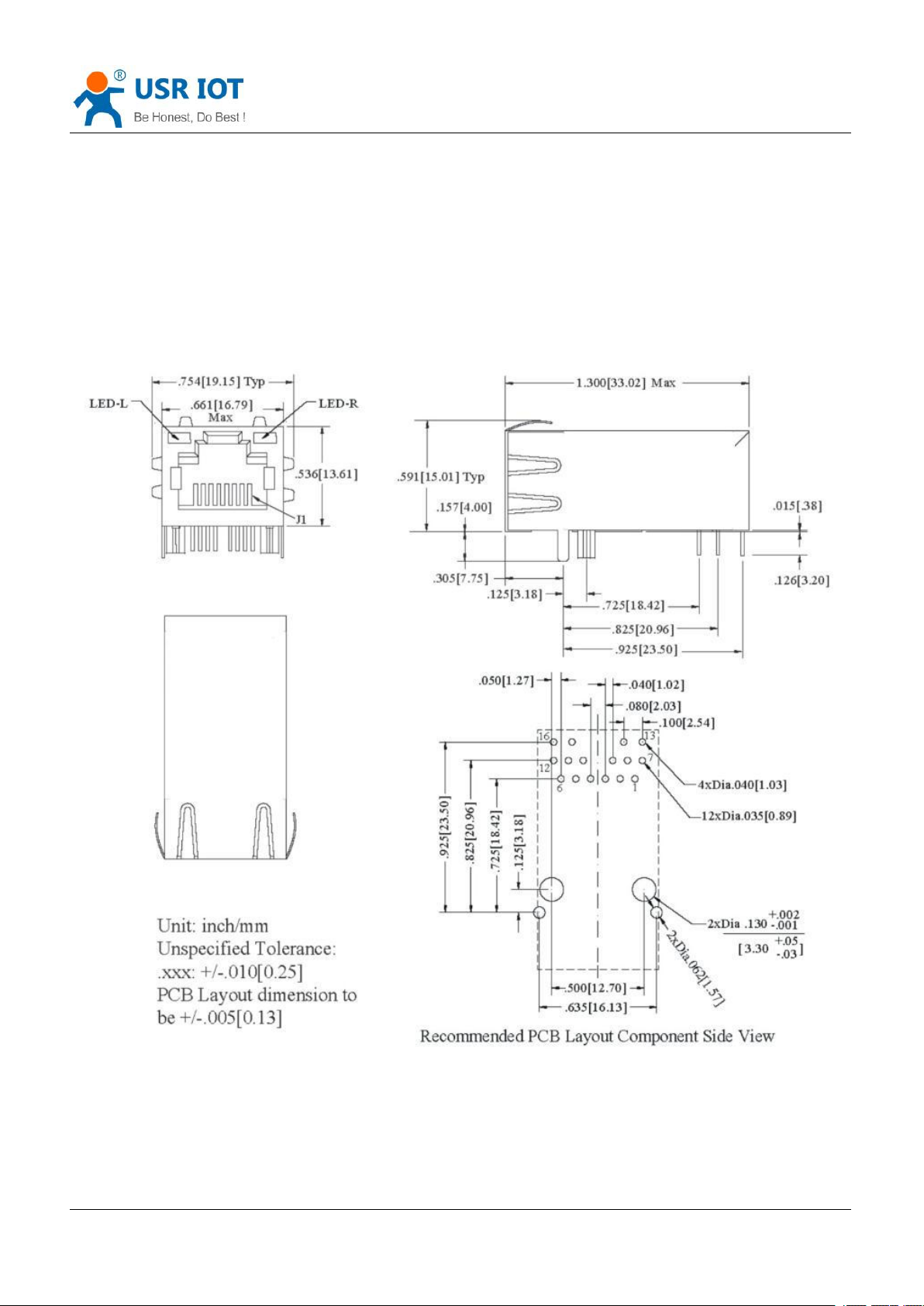
Module size: 33.03*19.01*19.15 mm, error ±0.2mm, pin size as follow:
Figure 1 Dimension diagram
Jinan USR IOT Technology Limited 3 / 9 h.usriot.com
Page 4
USR-K2 Hardware Manual www.usriot.com
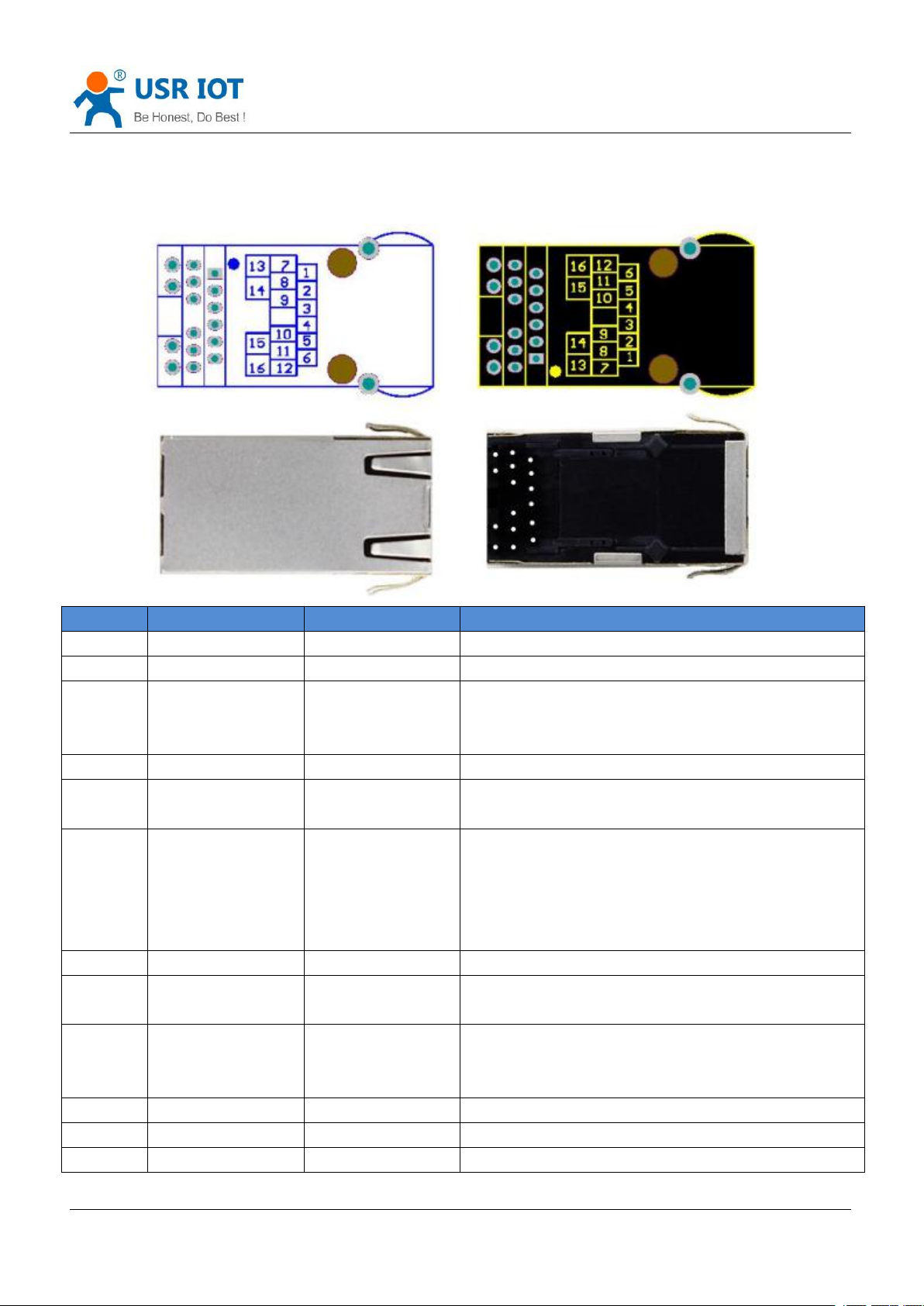
1.2. Pin Definition
PIN
Name
Signal Type
Definition
1NCNC
Not available
2NCNC
Not available
3
LINK
O
Can be used to indicate TCP connection status. After
establishing TCP connection and enabling LINK
function, led LINK will light.
4
RST
I
Inputting low level over 300ms to reset the module
5
485_EN
O
RS485 receiving/transmitting control pin, high level to
enable transmitting.
6
Reload(CFG)
I
After module powering off, pulling down Reload pin to
0V, then powering up, keeping Reload pin 0V over five
seconds and pull up Reload pin(3.3V), module will
restore default settings. Reload pin connects to
internal 10K Ohm pull-up resistor.
7
LED_DATA+
O
Ethernet interface LED_DATA+ pin
8
RXD
I
Serial port receiving pin(3.3V, TTL level) which needs
to connect to external 10K Ohm pull-up resistor.
9
TXD
O
Serial port transmitting pin(3.3V, TTL level) which
needs to connect to external 10K Ohm pull-up
resistor.
10
GND
P
Power ground
11
VCC
P
3.3V VCC
12
LED_LINK+
O
Ethernet interface LED_LINK+ pin
Jinan USR IOT Technology Limited 4 / 9 h.usriot.com
Page 5
USR-K2 Hardware Manual www.usriot.com
13
LED_DATA-
I
Ethernet interface LED_DATA- pin
14
LED_3V3
P
Power supply pin for Ethernet interface LED
15
LED_3V3
P
Power supply pin for Ethernet interface LED
16
LED_LINK-
I
Ethernet interface LED_LINK- pin
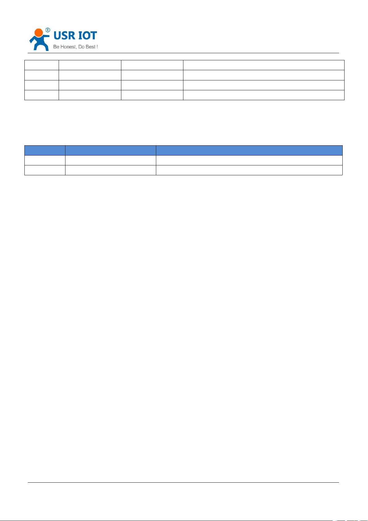
1.3. Ethernet interface LED
LED
Function
Description
Green
Indicating connection status
Green LED will light after module connecting to network
Yellow
Indicating data transmission
Yellow LED will blink when module has data transmission
Figure 2 Pin definition
Figure 3 Ethernet interface LED
Jinan USR IOT Technology Limited 5 / 9 h.usriot.com
Page 6
USR-K2 Hardware Manual www.usriot.com
2.Hardware Design
2.1. Typical Connection
2.2. Power Interface
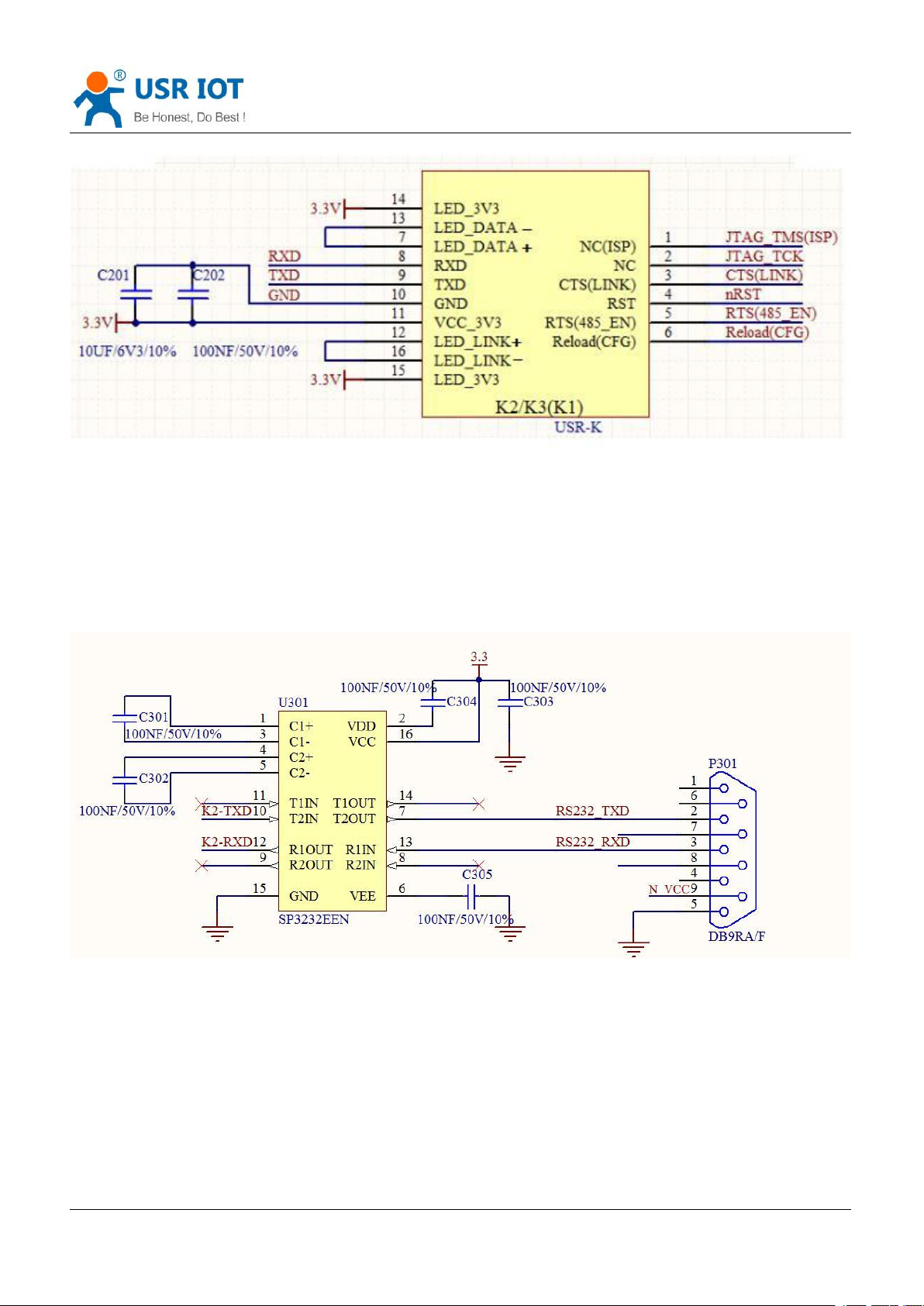
Figure 4 Typical connection
Note:
1.Connect two LED_3V3 pin to 3.3V power supply.
2.Connect 12 pin LED_LINK+ to 16 pin LED_LINK- which has connected to internal 1K Ohm series resistor.
3.Connect 7 pin LED_DATA+ to 13 pin LED_DATA- which has connected to internal 1K Ohm series resistor.
4.RST: Resetting module and taking effect in low level. RST pin has connected to internal 10K Ohm pull-up
resistor to 3.3V. When USR-K2 works in TCP Client mode, module will connect to TCP Server. After enabling
Reset function, module will reset if TCP connection can’t be established after trying 30 times.
5.Reload: After module powering off, pulling down Reload pin to 0V, then powering up, keeping Reload pin 0V
over five seconds and pull up Reload pin(3.3V), module will restore default settings. Reload pin connects to
internal 10K Ohm pull-up resistor.
6.TXD/RXD: Serial port data transmitting/receiving pin and should connect to 10K Ohm pull-up resistor.
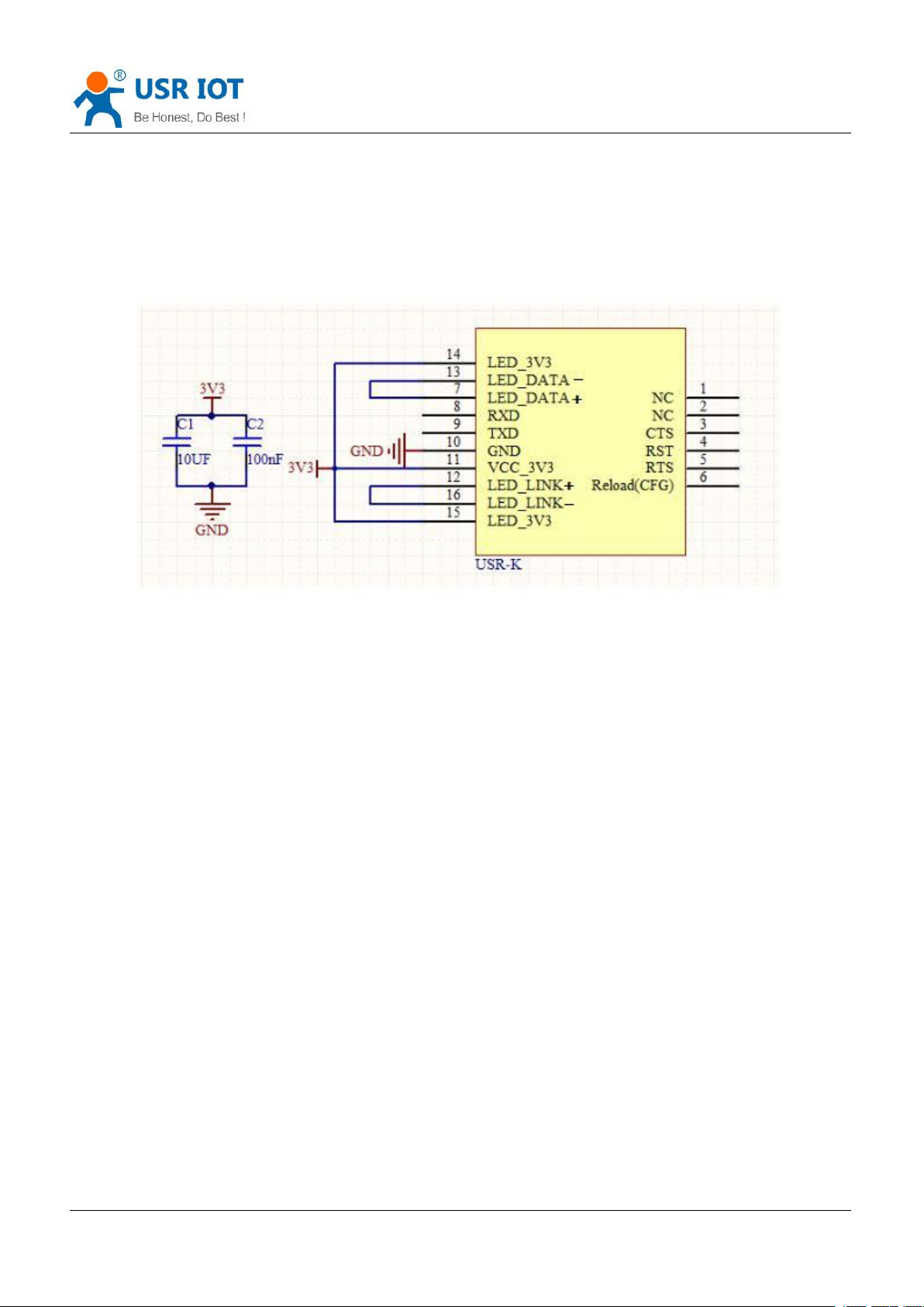
USR-K2 adopts 3.3V power supply and working current is [email protected]. Pin 11 is VCC 3.3V pin which can
connect to 10UF/6V3/10% and 100nF/50V/10% bypass capacitor to make module work stably. Circuit
diagram as follow:
Jinan USR IOT Technology Limited 6 / 9 h.usriot.com
Page 7
USR-K2 Hardware Manual www.usriot.com
2.3. UART Interface
Figure 5 Power interface
UART is serial data interface that can connect the RS-232 chip and transfer to the RS-232 level. UART
interface includes TXD/RXD.Taking the RS-232 level as a reference circuit diagram as follow:
Figure 6 RS232 level UART interface
When communicating to MCU with 3.3V, just connecting TXD of module to RXD of MCU and RXD of module
to TXD of MCU. When communicating to MCU with 5V, switching circuit is necessary.
Switching circuit diagram as follow:
Jinan USR IOT Technology Limited 7 / 9 h.usriot.com
Page 8

USR-K2 Hardware Manual www.usriot.com
Figure 7 Switching circuit
Jinan USR IOT Technology Limited 8 / 9 h.usriot.com
Page 9

USR-K2 Hardware Manual www.usriot.com
3.Contact
4.Disclaimer
5.Update History
Company: Jinan USR IOT Technology Limited
Address: Floor 11, Building No.1, No.1166, Xinluo Street, Gaoxin District, Jinan city, Shandong province,
250101 China
Tel: 86-531-88826739
Web: www.usriot.com
Support: h.usriot.com
Email: [email protected]
This document provide the information of USR-K2 products, it hasn’t been granted any intellectual property
license by forbidding speak or other ways either explicitly or implicitly. Except the duty declared in sales terms
and conditions, we don’t take any other responsibilities. We don’t warrant the products sales and use
explicitly or implicitly, including particular purpose merchant-ability and marketability, the tort liability of any
other patent right, copyright, intellectual property right. We may modify specification and description at any
time without prior notice.
2017-11-02 V1.3.01 created based on Chinese version V1.3.
Jinan USR IOT Technology Limited 9 / 9 h.usriot.com
 Loading...