

Page 1
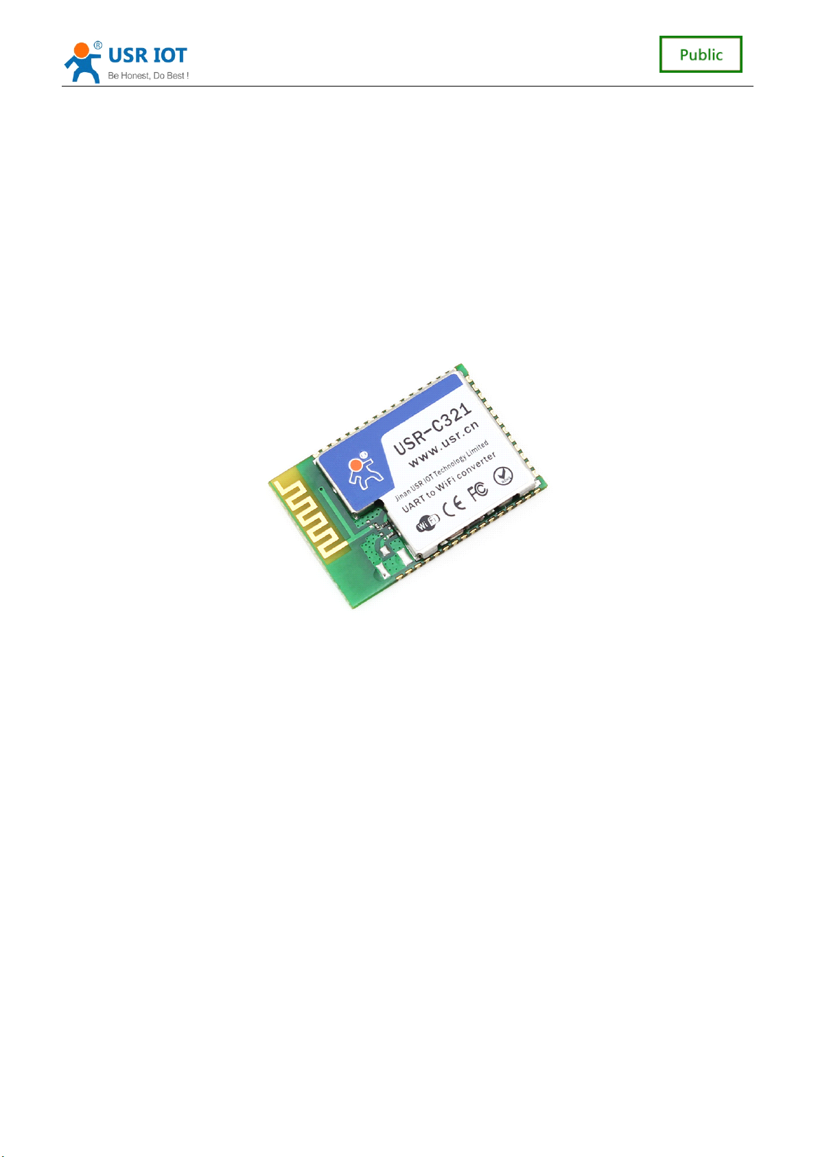
USR-C321 Low Power M inisize WiFi Module User Manual www.usr.so
Low
-
Low
-
-
- Low
Low Power
Power
Power
Power Minisize
USR-C32
USR-C32
USR-C32
USR-C32 1
Minisize
Minisize
Minisize WiFi
WiFi
WiFi
WiFi Module
V1.
V1.
V1.
V1. 1
1
1
1
Module
Module
Module User
1
1
1
User
User
User Manual
Manual
Manual
Manual
Support [email protected] GHz 802.11 b/g/n wireless standards
Support WEP
Support AP/STA working mode
Based on ARM Cortex-M4 kernel running frequency of 80 MHZ
Fully integrated serial port turn wireless TCP/UDP transmission function,the rate of serial
port up to 3M bps
Support 485 Control
Search in local area network (LAN) and wireless parameter s setting function
Support TCP/UDP Client registered packet mechanism
Support Simplelink/usrlink Networking configuration
Support c ustom web function
Support similar RFC2217 automatic baud rate adaptation function
Support AT+ simple instruction set configuration
Single 3.3 V power supply
Ultra low power mode, support deep dormancy
Support Internal/External(I-PEX) Antenna Option
Minisize:18.22mm*26.65mm*2.8mm SMT
FCC/CE Certificated
WPA/WPA2 security mode
、
1
1
1
1/41
41
41
41
Page 2

1
Module
1
Module
、
、
1
1
Module
Module Overview
、
、
1.1
1.1
1.1
1.1 Module
1.2
1.2
1.2
1.2 Characteristics
1.3
1.3
1.3
1.3 Product
1.4
1.4
1.4
1.4 Application
2
Hardware
2
Hardware
、
、
2
2
Hardware
Hardware Description
、
、
2.1
2.1
2.1
2.1 Pin
2.2
2.2
2.2
2.2 Antenna
2.3
2.3
2.3
2.3 Size
2.4
2.4
2.4
2.4 The
3
Product
3
Product
、
、
3
3
Product
Product Function
、
、
3.1
3.1
3.1
3.1 Work
3.2
3.2
3.2
3.2 Wireless
3.3
3.3
3.3
3.3 Socket
3.4
3.4
3.4
3.4 Custom
3.5
3.5
3.5
3.5 Search
3.6
3.6
3.6
3.6 TCP/UDP
3.7
3.7
3.7
3.7 Fast
3.8
3.8
3.8
3.8 Simplelink
3.9
3.9
3.9
3.9 RFC2217
3.10
3.10
3.10
3.10 Sleep
4
Parameter
4
Parameter
、
、
4
4
Parameter
Parameter Setting
、
、
4.1
4.1
4.1
4.1 Web
4.2
4.2
4.2
4.2 AT+
5
service
5
service
、
、
5
5
service
service and
、
、
Appendix
Appendix
Appendix
Appendix A:
Appendix
Appendix
Appendix
Appendix B:
Appendix
Appendix
Appendix
Appendix C:
Overview
Overview
Overview ..............................................................................................................................
Module
Module
Module Overview
Characteristics
Characteristics
Characteristics of
Product
Product
Product Feature
Application
Application
Application Area
Description
Description
Description ......................................................................................................................
Pin
Definitions
Pin
Definitions
Pin Definitions
Definitions
Antenna
Antenna
Antenna Shows
Size
and
Size
and
Size and
and Layout
The
Hardware
The
Hardware
The Hardware
Hardware Circuit
Function
Function
Function ............................................................................................................................
Work
Work
Work Mode
Wireless
Wireless
Wireless Network
Socket
Socket
Socket Communication
Custom
Custom
Custom web
Search
Search
Search in
TCP/UDP
TCP/UDP
TCP/UDP Client
Fast
Fast
Fast Access
Simplelink
Simplelink
Simplelink Configuration
RFC2217
RFC2217
RFC2217 Automatic
Web
Web
Web Page
AT+
AT+
AT+ Commands
Mode
Mode
Mode
Access
Access
Access Wi-Fi(usrlink)
Sleep
Sleep
Sleep Mode
Setting
Setting
Setting ...........................................................................................................................
Page
Page
Page Configuration
Commands
Commands
Commands Configuration
and
and
and support
A:
Contact
A:
Contact
A: Contact
Contact Information
B:
Disclaimer
B:
Disclaimer
B: Disclaimer
Disclaimer
C:
Update
C:
Update
C: Update
Update History
USR-C321 Low Power M inisize WiFi Module User Manual www.usr.so
..............................................................................................................................
..............................................................................................................................
.............................................................................................................................. 3
.......................................................................................................................
Overview
Overview
Overview
Feature
Feature
Feature
Area
Area
Area
Shows
Shows
Shows
Layout
Layout
Layout Recommendations
................................................................................................................................
................................................................................................................................
................................................................................................................................
................................................................................................................................
Network
Network
Network Mode
Communication
Communication
Communication
web
web
web function
in
local
in
local
in local
local area
Client
Client
Client Registration
Configuration
Configuration
Configuration
Automatic
Automatic
Automatic Baud
Mode
Mode
Mode Introduction
Configuration
Configuration
Configuration
support
support
support .......................................................................................................................
.......................................................................................................................
.......................................................................................................................
.......................................................................................................................
.......................................................................................................
of
Module
of
Module
of Module
Module
.........................................................................................................................
.........................................................................................................................
.........................................................................................................................
.........................................................................................................................
........................................................................................................................
........................................................................................................................
........................................................................................................................
........................................................................................................................
......................................................................................................................
......................................................................................................................
...................................................................................................................... 6
............................................................................................................................
............................................................................................................................
............................................................................................................................
............................................................................................................................
..........................................................................................................................
..........................................................................................................................
..........................................................................................................................
..........................................................................................................................
Recommendations
Recommendations
Recommendations
Circuit
Circuit
Circuit Design
............................................................................................................................
............................................................................................................................
............................................................................................................................ 11
Mode
Mode
Mode
function
function
function
area
network
area
network
area network
network
Registration
Registration
Registration Packet
Wi-Fi(usrlink)
Wi-Fi(usrlink)
Wi-Fi(usrlink)
Baud
Baud
Baud Rate
Introduction
Introduction
Introduction
...........................................................................................................................
...........................................................................................................................
........................................................................................................................... 21
Configuration
Configuration
Configuration
.......................................................................................................................
.......................................................................................................................
....................................................................................................................... 40
Information
Information
Information
......................................................................................................................
......................................................................................................................
......................................................................................................................
......................................................................................................................
History
History
History
.......................................................................................................
.......................................................................................................
.......................................................................................................
Design
Design
Design Reference
.........................................................................................................
.........................................................................................................
.........................................................................................................
.........................................................................................................
.........................................................................................................
.........................................................................................................
.........................................................................................................
.........................................................................................................
.............................................................................................................
.............................................................................................................
.............................................................................................................
.............................................................................................................
....................................................................................................
....................................................................................................
....................................................................................................
....................................................................................................
......................................................................................................
......................................................................................................
......................................................................................................
......................................................................................................
Rate
Rate
Rate Function
....................................................................................................
....................................................................................................
....................................................................................................
....................................................................................................
.......................................................................................................
.......................................................................................................
.......................................................................................................
.......................................................................................................
.....................................................................................................
.....................................................................................................
.....................................................................................................
.....................................................................................................
..............................................................................................................
..............................................................................................................
..............................................................................................................
..............................................................................................................
Catalogue
Catalogue
Catalogue
Catalogue
....................................................................................
....................................................................................
....................................................................................
....................................................................................
............................................................................
Reference
Reference
Reference
...............................................................................................
...............................................................................................
...............................................................................................
...............................................................................................
Packet
Packet
Packet Mechanism
Function
Function
Function
............................................................................................
............................................................................................
............................................................................................
............................................................................................
............................................................................
............................................................................
............................................................................
Mechanism
Mechanism
Mechanism
.........................................................................
.........................................................................
.........................................................................
.........................................................................
3
3
3
3
3
3
3
3
3
3
3
4
4
4
4
5
5
5
5
6
6
6
6
6
6
6
7
7
7
7
8
8
8
8
9
9
9
9
11
11
11
11
11
11
11
12
12
12
12
13
13
13
13
14
14
14
14
14
14
14
14
..........................................................
..........................................................
..........................................................
..........................................................
15
15
15
15
15
15
15
15
18
18
18
18
18
18
18
18
19
19
19
19
21
21
21
21
21
21
21
28
28
28
28
40
40
40
41
41
41
41
41
41
41
41
41
41
41
41
2
2
2
2 / 41
41
41
41
Page 3

USR-C321 Low Power M inisize WiFi Module User Manual www.usr.so
1
、
Module
1
、
Module
1
1 、
、 Module
Module Overview
1.1
Module
1.1
Module
1.1
1.1 Module
Module Overview
USR - C321 is a low-cost module of the series wifi module C32 x .The module is a low-power
802.11 b/g/n modules that design for achieving the application of the embedded system,
wireless network communication. Through the module, the customer can set a physical device
connected to a wifi network, so as to realize the control and management of the Internet of iot.
The hardware of module integrate MAC, baseband chip, rf transceiver unit, as well as the
power amplifier; Adopting CC3200 chip of TI company, the kernel of industrial-grade ARM
architecture (M4 kernel, running frequency of 80 MHZ. The internal ultra-low power operation
mechanism, can run effectively low-power module; Support WiFi protocol and TCP/IP protocol,
the user only needs simple configuration, can achieve the function of UART devices connected
to the Internet.
Small size, easy to welding in the customer product veneer of hardware circuit. And the
module can choose the application of the internal or external antenna, supplying customers
multiple choices.
Module size: 18.22 mm * 26.65 mm * 2.8 mm SMT assembly
The basic function of the module is described below:
Can work in AP mode for other WIFI devices access communication, can also work in
the STA mode, access to the wireless router to realize communication
With a Socket communication links, can be set to the TCP Server, TCP Client, and UDP
Server, UDP Client communication; The Socket in the TCP Server mode, can support
up to four TCP Client connection
Module supports UART translate, can use AT commands to arbitrary switching.
Overview
Overview
Overview
Overview
Overview
Overview
If you have problems when use the module,you can submit the question to
http://h.usriot.com
http://h.usriot.com
http://h.usriot.com
http://h.usriot.com .We will solve your question at the first time .
1.2
Characteristics
1.2
Characteristics
1.2
1.2 Characteristics
Characteristics of
Support [email protected] GHz 802.11 b/g/n wireless standards
Support WEP-A
Support AP/STA working mode
Based on ARM Cortex-M4 kernel running frequency of 80 MHZ
Fully integrated serial port turn wireless TCP/UDP transmission function,the rate of serial
port up to 3M bps
Support 485 control
Search in local area network (LAN) and wireless parameter s setting function
Support TCP/UDP Client registered packet mechanism
Support Simplelink/usrlink Networking configuration
Support similar RFC2217 automatic baud rate adaptation function
Support AT+ simple instruction set configuration
of
Module
of
Module
of Module
Module
WPA/WPA2 security mode
、
3
3
3
3 / 41
41
41
41
Page 4
USR-C321 Low Power M inisize WiFi Module User Manual www.usr.so
Single 3.3 V power supply
Ultra low power mode, support deep dormancy
Support Internal/External(I-PEX) Antenna Option
Minisize:18.22mm*26.65mm*2.8mm SMT
FCC/CE Certificated
1.3
Product
1.3
Product
1.3
1.3 Product
Product Feature
Wireless P ara
meter
Feature
Feature
Feature
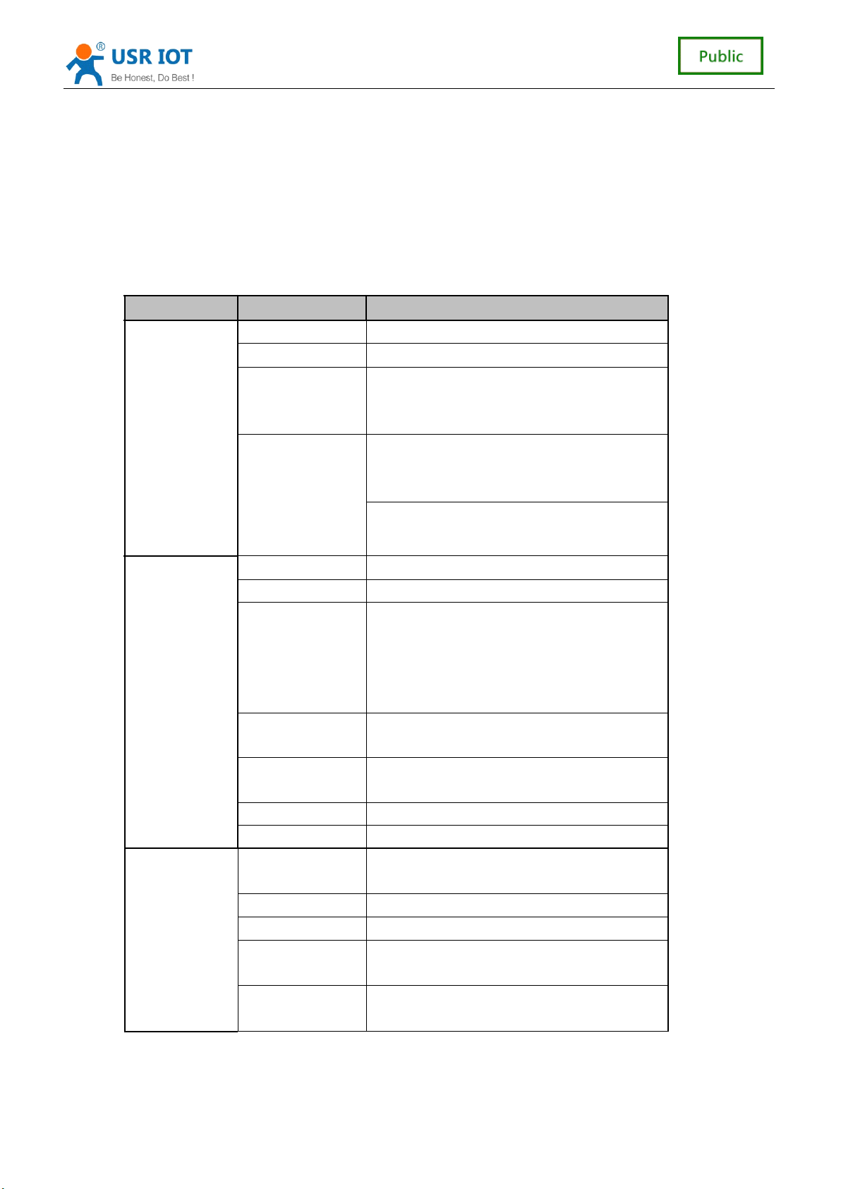
Module parameters
classify parameter value
Certification FCC/CE
Wlan S tandard 802.11 b/g/n
17.0 dBm @ 1 DSSS
T ransmit P ower
R eceive
S ensitivity
17.25 dBm @ 11 CCK
13.5 dBm @ 54 OFDM
– 94.7 dBm @ 1 DSSS
– 87.0 dBm @ 11 DSSS
– 73.0 dBm @ 54 OFDM
Hardware
S oftware
A ntenna
D ata I nterface UART 300-3M bps
W orking V oltage 3.0V~3.6V
W orking C urrent
W orking
T emperature
S torage
T emperature
S ize 18.22mm*26.65mm*2.8mm
Footprint SMT
Wireless
N etwork T ype
S ecurity R egime WEP/WPA-PSK/WPA2-PSK
Encryption Type TKIP , AES , TKIP/AES
N etworking
P rotocol
User
Configuration
External : I-PEX
Internal : On-board antenna
( voltage 3.3 V )
Continue to send : ~75mA
normal mode : average: ~18mA , top: 200mA
In the web : 3.5mA
Standby : lowest 25uA
- 40 ℃ - 85 ℃
-45 ℃ - 125 ℃
AP/STA
IPv4, TCP/UDP
AT+ instruction set
Web
4
4
4
4 / 41
41
41
41
Page 5

1.4
Application
1.4
Application
1.4
1.4 Application
Application Area
Cloud C onnected
H ome A utomation
H ousehold A ppliances
A ccess C ontrol
S ecurity and P rotection S ystem
Smart Energy
I ndustrial C ontrol
I ntelligent E lectrical O utlet B ox/ I nstrument M easurement
IP N etwork S ensor N odes
W ireless P rinter
Area
Area
Area
USR-C321 Low Power M inisize WiFi Module User Manual www.usr.so
5
5
5
5 / 41
41
41
41
Page 6
2
、
Hardware
2
、
Hardware
2
2 、
、 Hardware
Hardware Description
2.1
Pin
2.1
2.1
2.1 Pin
Definitions
Pin
Definitions
Pin Definitions
Definitions
Description
Description
Description
USR-C321 Low Power M inisize WiFi Module User Manual www.usr.so
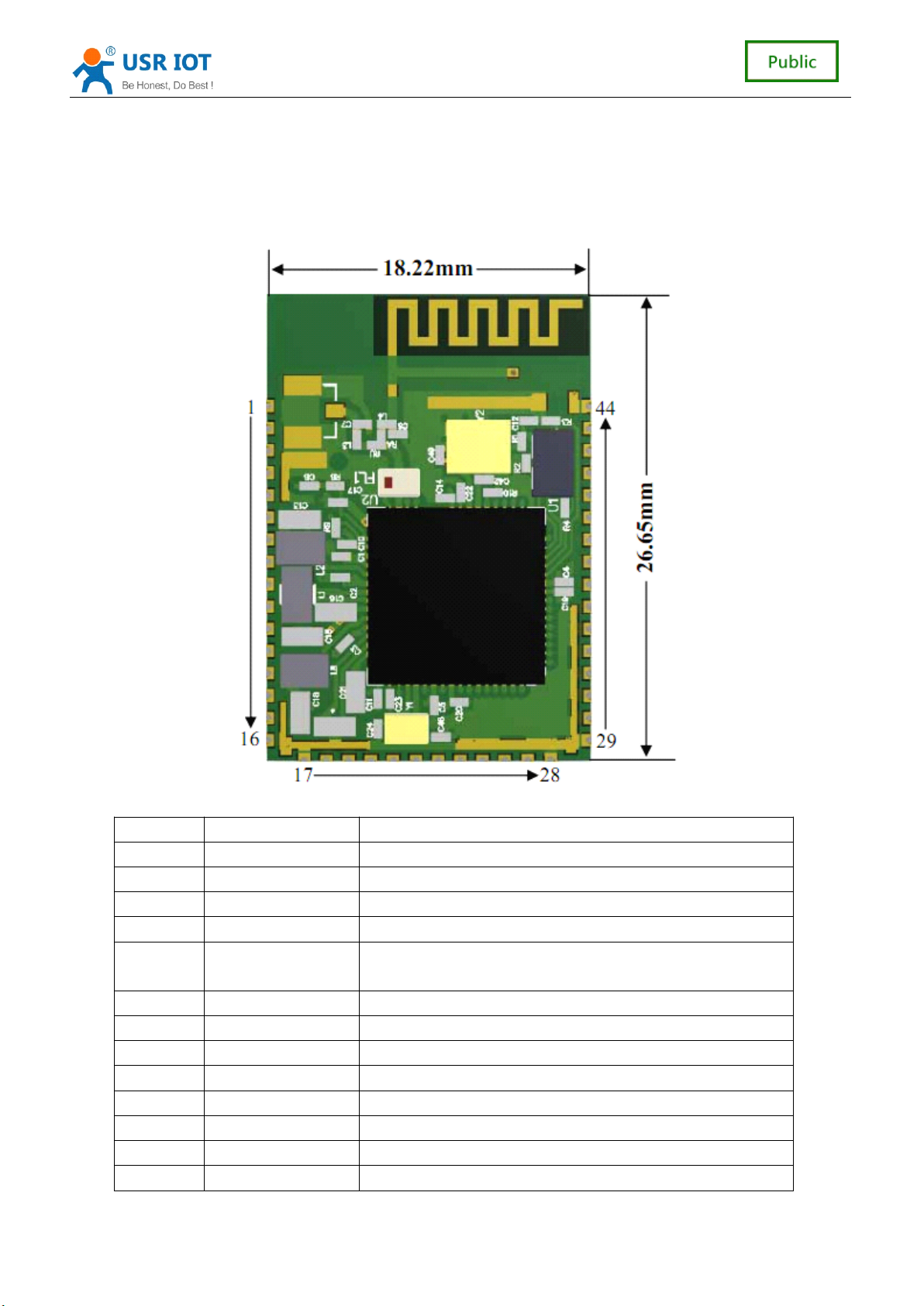
The module pin
P in Net Name F unctional D escription
1 GND GND
2 GPIO General GPIO
3 GPIO General GPIO
4 nReset Module reset pin, low level effectively
2.4
The
5 SOP2
6 SOP1 default NC
7 SOP0 default NC
8 ANA DC-DC The RF power output pin, hung up
9 NC NC
10 NC NC
11 GND GND
12 GND GND
13 VBT_CC Power input pin, please connect + 3.3 V
Start the choice, see 2.4
Reference
Reference
Reference
Reference
6
41
6
41
6
6 / 41
41
2.4
2.4 The
Hardware
The
Hardware
The Hardware
Hardware Circuit
Circuit
Circuit
Circuit Design
Design
Design
Design
Page 7

USR-C321 Low Power M inisize WiFi Module User Manual www.usr.so
14 VDD_ANA2 RF Power input pin, please connect + 3.3 V
15 GPIO General GPIO
16 NC NC
17 GND GND
18 GPIO General GPIO
19 UART TX UART TX for
20 UART RX UART RX for module
Down 1-3 Seconds start simplelink setting.
21 nReload
22 nReady
23 nLink
24 UART CTS A serial port flow control pin CTS
25 UART RTS A serial port flow control pin RTS
26 GPIO General GPIO
27 GPIO General GPIO
28 GND GND
29 GND GND
30 GPIO General GPIO
31 GPIO General GPIO
32 GPIO General GPIO
33 GPIO General GPIO
34 GPIO General GPIO
35 GPIO General GPIO
36 GPIO General GPIO
37 GPIO General GPIO
38 GPIO General GPIO
39 NC NC
40 NC NC
41 GPIO General GPIO
42 NC NC
43 NC NC
44 GND GND
Down more 3 seconds set the Module to factory default
setting
Work instructions pin of module, low effective, connect an
external LED
WiFi link pin of module, low effective, connect an external
LED
module
2.2
Antenna
2.2
Antenna
2.2
2.2 Antenna
Antenna Shows
Shows
Shows
Shows
Module has two antenna version, internal antenna and external IPEX interface respectively:
7
41
7
41
7
7 / 41
41
Page 8

2.3
Size
2.3
Size
2.3
2.3 Size
Size and
Advise PCB F ootprint :
and
and
and Layout
USR-C321 Low Power M inisize WiFi Module User Manual www.usr.so
Internal Antenna External:I-PEX
Layout
Layout
Layout Recommendations
Recommendations
Recommendations
Recommendations
Cloth plate specification:
1) Internal Antenna
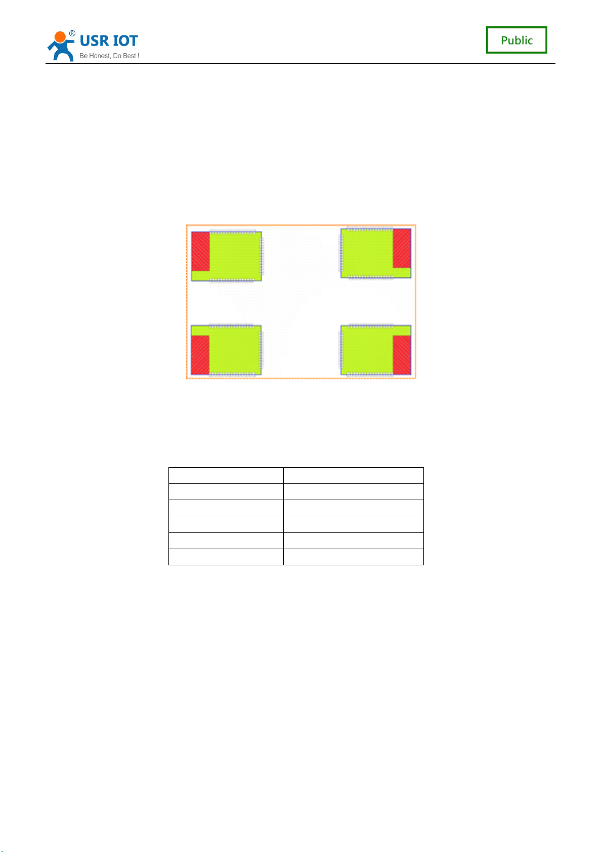
Customers to use the internal antenna, the need to abide by the following
considerations and internal antenna module placed general rules:
On the user's PCB, and grey shaded area above the corresponding area cannot be
8
41
8
41
8
8 / 41
41
Page 9
USR-C321 Low Power M inisize WiFi Module User Manual www.usr.so
placed components and GND.
Antennas away from the metal, at least distance with high components around
more than 10 mm;
Antenna part cannot be metal shell, plastic shell need at least more than 10 mm
away from the antenna;
It is suggested that module is placed in the following areas of the user's board as far
as possible, to reduce the influence of the antenna and wireless signal, and at the same
time, please consult someone technical support staff to assist the placement of
modules and related areas of the Layout design.
2) external antenna
Customers to use external antenna lead, according to the requirement of the
IEEE802.11 b/g/n standard, need to connect the 2.4 g external antenna. External antenna
using IPEX interface. The parameters of the external antenna requirements in the table
below details.
item paramter
frequency range 2.4~2.5GHz
impedance 50 Ohm
VSWR 2 (Max)
Return Loss -10dB (Max)
Connection Type IPEX
2.4
The
2.4
2.4
2.4 The
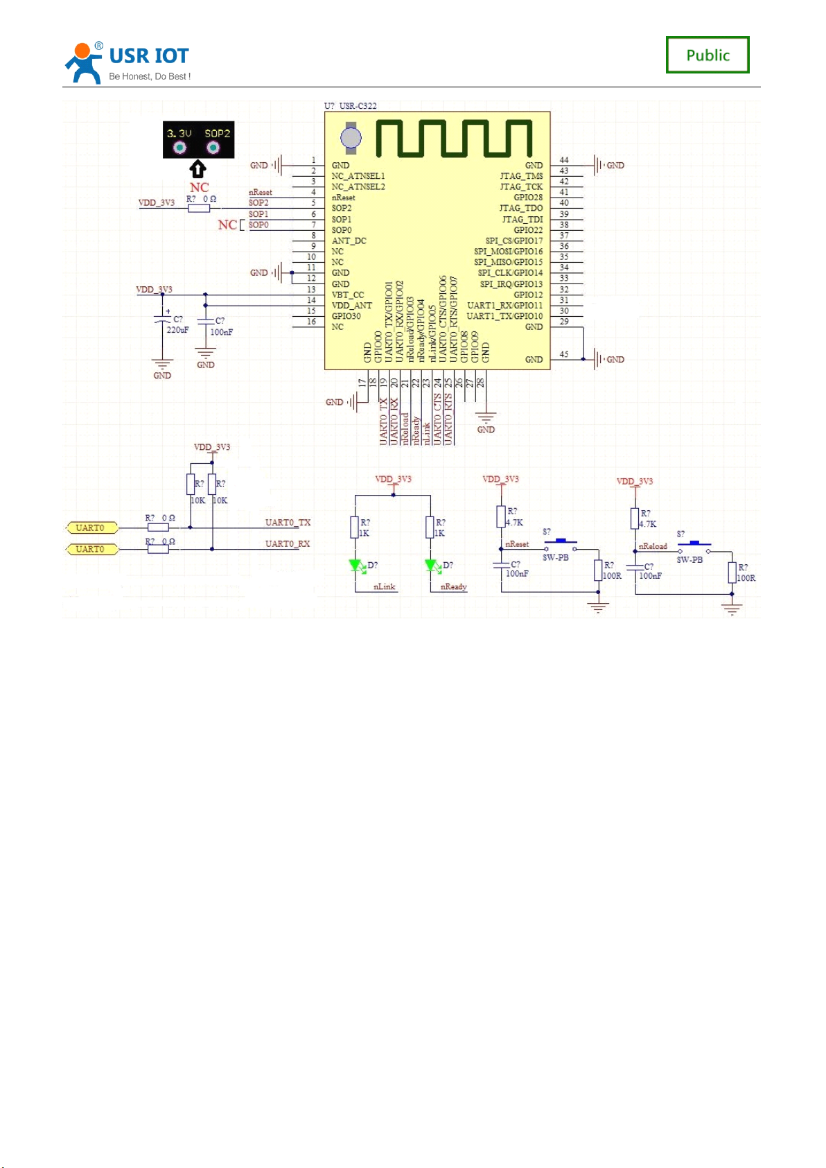
The hardware design considerations:
Need to add more than 200uf capacitance module power supply pin.
SOP0 、 SOP1 、 no connect .
SOP2 reserved a port,used to upgrade firmware in uart0
Reset 、 Reload n eed to pick up on the 4.7 K resistor.
nLink,nReady Effective for low level output.
Serial port RXD, TXD series a 0 Ω resistance
Serial port RXD, TXD need to pick up on the 10K resistor.
Hardware
The
Hardware
The Hardware
Hardware Circuit
Circuit
Circuit
Circuit Design
Design
Design
Design Reference
Reference
Reference
Reference
9
9
9
9 / 41
41
41
41
Page 10
USR-C321 Low Power M inisize WiFi Module User Manual www.usr.so
10
10
10
10 / 41
41
41
41
Page 11

USR-C321 Low Power M inisize WiFi Module User Manual www.usr.so
3
、
Product
3
、
Product
3
3 、
、 Product
Product Function
3.1
Work
3.1
Work
3.1
3.1 Work
Work Mode
Mode
Mode
Mode
Function
Function
Function
Module consists of two work modes: translate mode and command mode
Translate
Translate
Translate
Translate Mode
Mode
Mode
Mode
In this mode, the module realizes the UART and transparent transmission between
network, realize common serial data transfer between devices and network equipment.
Command
Command
Command
Command Mode
Mode
Mode
Mode
In this mode, the user can through the AT command to UART module and query
and network parameters Settings. When using the AT + ENTM exit command mode,
the default back to translate mode.
3.1.1
Translate
3.1.1
Translate
3.1.1
3.1.1 Translate
Translate Mode
1.
Translate
1.
Translate
1.
1. Translate
Translate Mode
Mode
Mode
Mode
Mode
Mode
Mode
UART interface can transparent transmission mode has the advantage of UART
interface and network communication of the plug and play, which reduce the complexity of
the user to a great extent. Modules to work in a transparent transmission mode, the users
only need to configure the necessary parameters, UART interface and network
communication can be realized. After power on, module automatically connected to the
wireless network and server configured.
Transparent transmission mode is fully compatible with your own software platform,
reducing the workload of integration of wireless data transmission software development.
Users need to preset parameters usually include:
Wireless network parameters
SSID
security mode
secret key
TCP/UDP parameter
protel
connection type
destination port
destination address
UART parameter
Baud rate
data bits
stop bit
parity bit
Hardware flow control
2.
UART
2.
UART
2.
2. UART
UART Frame
Frame
Frame
Frame Scheme
Scheme
Scheme
Scheme
Module in the receiving UART data, will continue to check the time interval of two
adjacent bytes. If the time interval is greater than the set packing time (default 5 ms, can be
11
11
11
11 / 41
41
41
41
Page 12

USR-C321 Low Power M inisize WiFi Module User Manual www.usr.so
set up by the
command mode is greater than 1 k bytes are discarded the received data, in translate mode
is greater than 1 k bytes are sent packing.
3.1.2
Command
3.1.2
Command
3.1.2
3.1.2 Command
Command Mode
In command mode, the module will no longer work to translate, UART port
for receiving the
module, UART for querying and setting module, network and other related parameters.
3.2
Wireless
3.2
Wireless
3.2
3.2 Wireless
Wireless Network
There are two kinds of wireless module WIFI working mode: the
provide users with flexible network mode and the network topology method.
< Nouns that >
AP:The wireless access point, is the center of a wireless network node. Commonly
used wireless router is an
STA: wireless site, is a wireless network terminal. Such as notebook computer, PDA,
etc.
AT
+ UARTTE), argues that the end of a frame, or has been receiving data, in
Mode
Mode
Mode
AT
command, the user can through UART port to send
Network
Network
Network Mode
Mode
Mode
Mode
AP,
other wireless terminal can be interconnected by AP
AT
commands to
STA
and
AP,
AT
this time
can
3.2.1
Module
3.2.1
Module
3.2.1
3.2.1 Module
Module As
Module as the
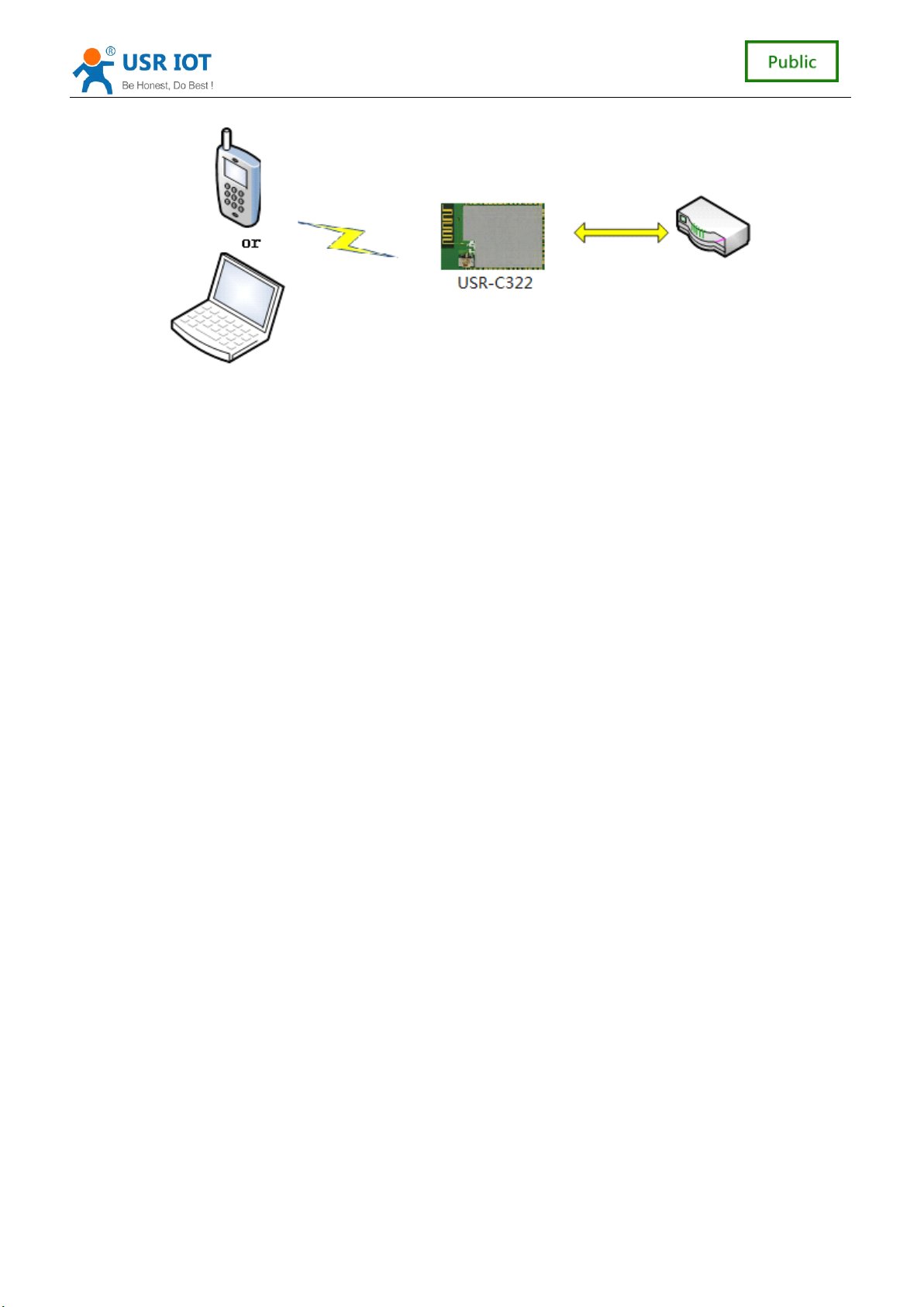
of a router AP and many STA, the following figure. Its characteristic is AP in a central
position, communication between the
3.2.2
3.2.2
3.2.2
3.2.2 Module
Module
Module
Module As
Modules as AP mode, can achieve phone/PAD/computer without any configuration, fast
access module for data transmission. In addition, you can login module internal web page
to set parameters
As
As
As a
As
As
As a
a
a
a STA
a
a
a AP
STA
STA
STA
STA
is one of the most commonly used network mode, and is composed
STA
forward by
AP
AP
AP
AP.
12
12
12
12 / 41
41
41
41
Page 13
USR-C321 Low Power M inisize WiFi Module User Manual www.usr.so
<
note
<
<
< note
3.2.3
Encryption
3.2.3
Encryption
3.2.3
3.2.3 Encryption
Encryption Type
>
note
>
note >
> : module in AP mode, can support only 1
Type
Type
Type
STA
access devices.
Encryption is scrambling to message data, ensure the security of data transmission,
increase the security of communication. Support multiple wireless network encryption
methods, including:
WEP
WPA-PSK/TKIP
WPA-PSK/AES
WPA2-PSK/TKIP
WPA2-PSK/AES
3.3
Socket
3.3
Socket
3.3
3.3 Socket
Socket Communication
Communication
Communication
Communication
The module has a TCP Socket. When the module in translate mode, to write the data of
the UART interface module, module will automatically send a Socket; Module through
the Socket received data, send out through the UART interface.
Socket works include: the TCP Server, the TCP Client, UDP Client, and UDP Server,
please refer to the
AT
command set method in the
AT
+ SOCKA instruction set or
through a web page Settings.
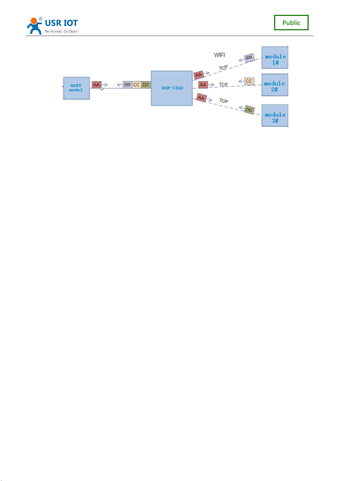
When a TCP Server Socket set, can support up to four TCP Client TCP link connection.
In a multiple TCP link connection mode, from the TCP transport data will be forwarded
to them one by one on the UART interface. Come from the UART interface data will be
copied into a more, in every TCP forwarding a link. Specific data flow diagram shown
below:
13
13
13
13 / 41
41
41
41
Page 14
USR-C321 Low Power M inisize WiFi Module User Manual www.usr.so
When the Socket set to UDP Server, if a serial port receives data first, module sends
the data to the already set
data source address, the module will remember after a serial port, after receipt of the
data module will be transmitted to the address data.
When the module is set to the UDP Client module only to have set the IP and port to
send data, and receive only has set the IP and port address data
Settings), other address to send more data is not forwarded to the UART.
IP,
port
(AT
+ SOCKA set), if the UDP Server receives data,
(AT
+ SOCKA
3.4
Custom
3.4
Custom
3.4
3.4 Custom
Custom web
USR
-
your own web page. Please refer to the specific implementation method " reference : USR-C32 1
custom ed web function ".
3.
5
Search
3.
5
Search
3.
3. 5
5 Search
Search in
Module support within the local area network (LAN) search function, that is, when the
module is connected to a wireless router, the user can through to a fixed port sends UDP
broadcast way, to get the IP address of the module of the current, in order to realize the search
and communications equipment. SEARCH the port and keyword can be set by the
SEARCH commands, default: 48899, www.usr.cn.
Search tool operation process:
1. Through the UDP broadcast (broadcast address: xx. Xx. Xx. 255, port: 48899) to send a
password, the default password is: "www.usr.cn", the longest can be set up 20 bytes.
web
web
web function
C322 support Custom web function. User can modify the web page content or add
in
in
in local
function
function
function
local
local
local area
area
area
area network
network
network
network
AT
+
2. Module after receiving the password, if the password is correct, the module to enter
configuration mode, to the address (unicast, source port) send the local IP address, MAC
address, the module name, version number.
D8B04CFC0000, USR - C321, 01.01.10). Module to enter configuration mode set if not
received within 30 seconds after the command, the module will exit the configuration mode, the
user needs to send search command word, enter configuration mode.
(IP,
MAC, MID, ver 10.10.100.254,
14
41
14
41
14
14 / 41
41
Page 15
USR-C321 Low Power M inisize WiFi Module User Manual www.usr.so
3. Users can through the network to the port to send
module working state, the
Note: search tools and modules must be within the same LAN, if multiple
router, run the search tools of the computer and even on the router. This search tool to search
all of the STA.
3.
6
TCP/UDP
3.
6
TCP/UDP
3.
3. 6
6 TCP/UDP
TCP/UDP Client
When the module working in TCP or UDP Client Client mode, the user can open registration
packet mechanism, in order to realize the server to the distinction between the data source,
data of different equipment monitoring. MAC and ID registration packet is divided into two kinds,
MAC is 6 bytes, ID 0-65535, ID value can be set. Registration packet ID is mainly used for the
D2D software of the company..
Registered packet opened and closed by
Registered packet implementation mechanism is as follows:
TCP Client: There are two kinds of TCP Client: registration mechanism:
1 Just send a registration packet, when the module is connected to the TCP Server
module will send TCP Server MAC (6 bytes) or ID (4 bytes), Server by MAC or ID to
distinguish between different devices.
2 Every packet of data has registration information, TCP Client after the link to the server,
a serial port receives each packet of data to increase MAC or ID, to distinguish between
equipment. ID or MAC choice, can be set by the
UDP Client: each module on the sending UDP packets, MAC or ID will increase in each
packet header information, and then send.
Client
Client
Client Registration
AT
command format with a serial port the
Registration
Registration
Registration Packet
Packet
Packet
Packet Mechanism
Mechanism
Mechanism
Mechanism
AT
+ REGENA.
AT
commands to set up and read the
AT
command.
STA
AT
+ REGENA.
even on a
3.
7
Fast
3.
7
Fast
3.
3. 7
7 Fast
Fast Access
When one module works in AP mode, it opens a UDP port used to receive fast access Wi-Fi
commands, the port number is 49000. The phone PDA can directly connect to Wi-Fi network of
the module, send commands to search router list and set SSID and password. After the
completion of set up, module will automatically restart, connected to the router, work in the STA
mode at this time.
Protocol format:
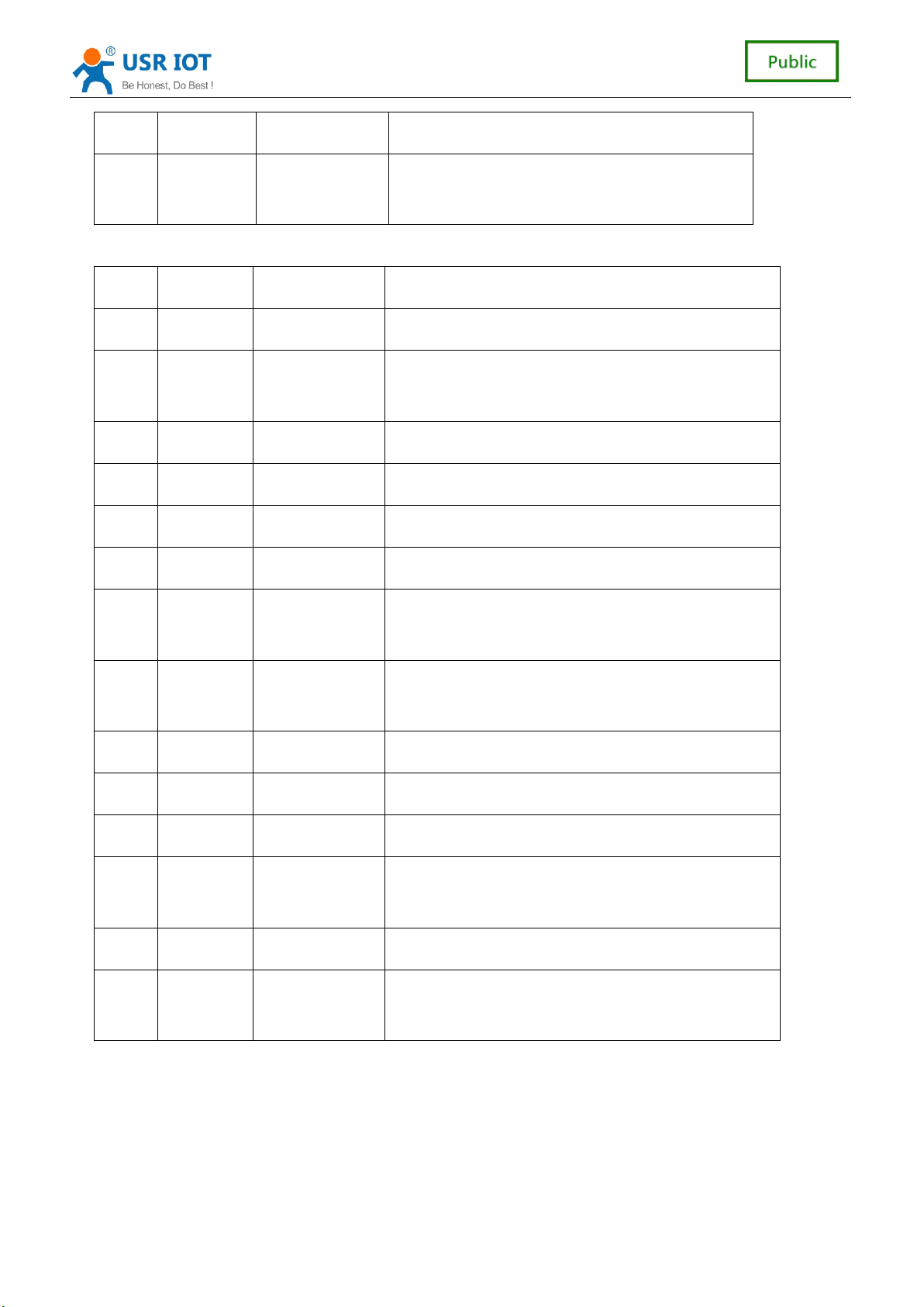
Searching command
No Name Num of Bytes Description
1 head 1 fixed value:0xFF
2 length 2 Sum of data bytes from length bytes to check
Access
Access
Access Wi-Fi(usrlink)
Wi-Fi(usrlink)
Wi-Fi(usrlink)
Wi-Fi(usrlink)
byte(not contain length bytes and check byte).
15
15
15
15 / 41
41
41
41
Page 16
USR-C321 Low Power M inisize WiFi Module User Manual www.usr.so
3 cmd 1 Command type, 0x01
4 check 1 Sum of bytes from head (not contained) byte to
check byte (not contained).
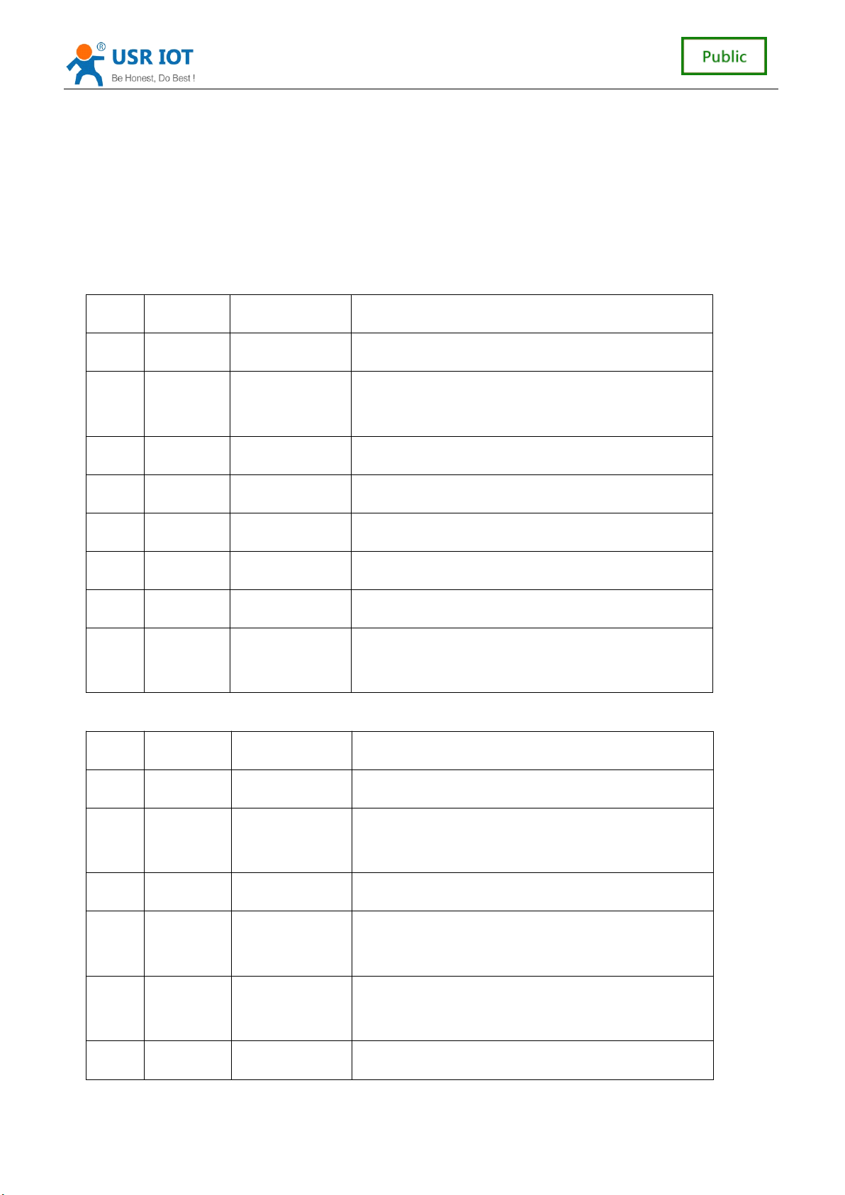
Response for searching
No Name Num of Bytes Description
1 head 1 fixed value:0xFF
2 length 2 Sum of data bytes from length bytes to check
byte(not contain length bytes and check byte).
3 cmd 1 Command type, 0x81
4 AP num 1 The number of AP what module scans
5 SSID1 Unsized The SSID of router 1
6 separator 1 Separator of SSID1, fixed value:0x00
7 Signal
1 Signal strength of router 1,0~100:0%~100%
strength1
8 separator 2 Separator of signal strength1, fixed value:
0x0D,0x0A
… … … ………
M SSID n Unsized The SSID of router n
M+1 separator 1 Separator of SSID n, fixed value:0x00
M+2 Signal
1 Signal strength of router n,0~100:0%~100%
strength
M+3 separator 2 fixed value:0x0D,0x0A
M+4 check 1 Sum of bytes from head (not contained) byte to
check byte (not contained).
Example:
Data from phone PDA to module (HEX): FF 00 01 01 02
Data from module to phone PDA (HEX): FF 00 14 81 02 54 45 53 54 31 00 40 0D 0A 54 45
53 54 32 00 37 0D 0A 1F
16
41
16
41
16
16 / 41
41
Page 17
USR-C321 Low Power M inisize WiFi Module User Manual www.usr.so
Explanation:
The phone PDA send searching command to module, the response from module is: SSID
of router1 is “ TEST1 ” , signal strength of router1 is 64%; SSID of router2 is “ TEST2 ” , signal
strength of router2 is 55%.
Note: The information of routers is ordered by signal strength.
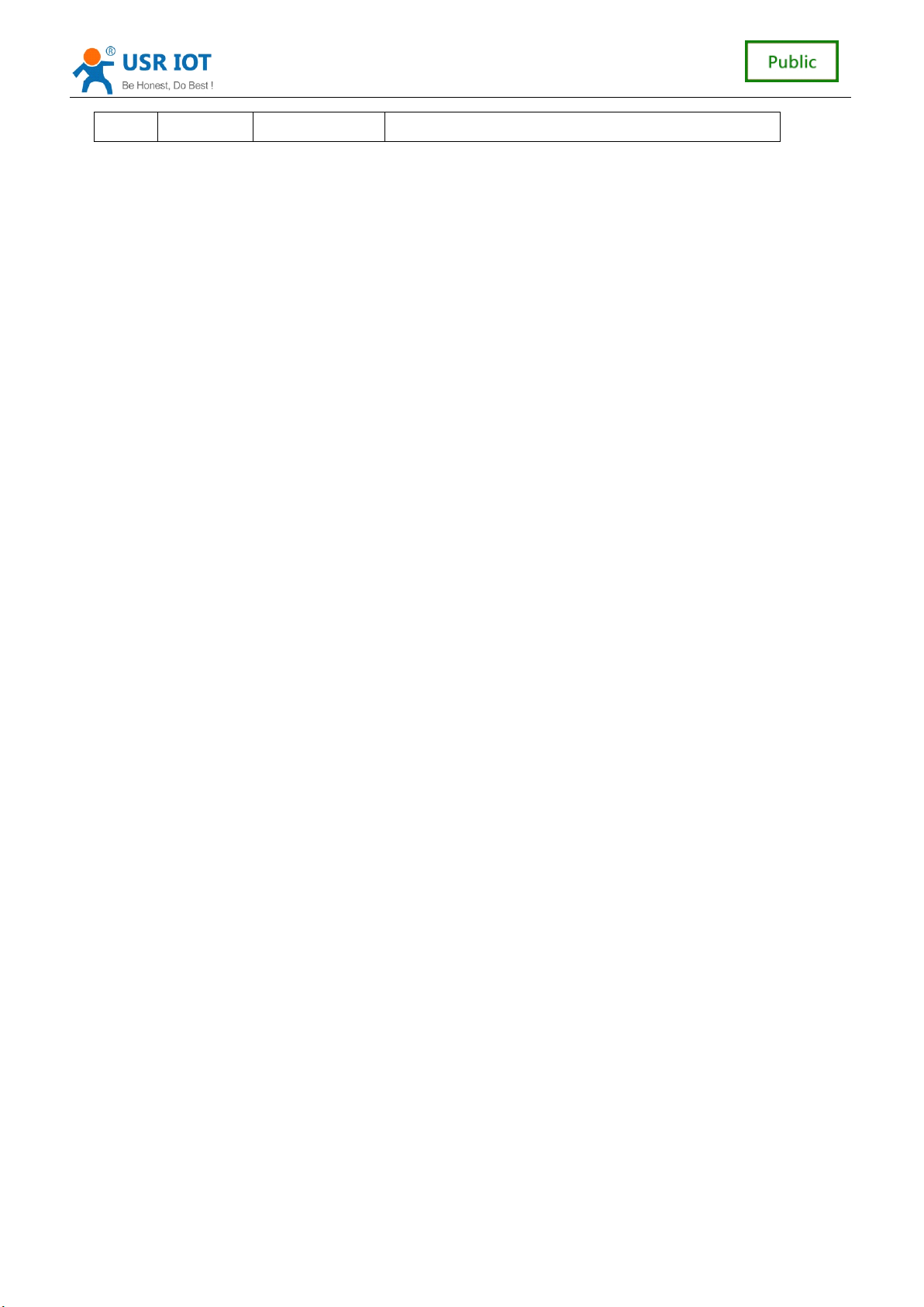
a) Setting Command
No Name Num of Bytes Description
1 head 1 fixed value:0xFF
2 length 2 Sum of data bytes from length bytes to check byte
(not contain length bytes and check byte).
3 cmd 1 Command type, 0x02
4 reserve 1 fixed value:0x00
5 SSID Unsized SSID of router
6 separator 2 fixed value:0x0D,0x0A
7 password Unsized Password of router
8 check 1 Sum of bytes from head (not contained) byte to
check byte (not contained).
Response for Setting
No Name Num of Bytes Description
1 head 1 fixed value:0xFF
2 length 2 Sum of data bytes from length bytes to check
byte(not contain length bytes and check byte).
3 cmd 1 Command type, 0x82
4 Check for
SSID
5 Check for
password
1 If the SSID set by PDA exist, check value is 0x01,
otherwise is 0x00.
1 If the form of password set by PDA is correct, check
value is 0x01, otherwise is 0x00.
6 check 1 Sum of bytes from head (not contained) byte to
17
41
17
41
17
17 / 41
41
Page 18
USR-C321 Low Power M inisize WiFi Module User Manual www.usr.so
check byte (not contained).
Example:
Data from phone PDA to module (HEX): FF 00 0F 02 00 54 45 53 54 31 0D 0A 31 32 33 34
35 36 CE
Data from module to phone PDA (HEX): FF 00 03 82 01 01 87
Explanation:
The phone PDA send setting command to module, SSID is set to “ TEST1 ” , password is set
to “ 123456 ” . The response from module is that the “ TEST1 ” Wi-Fi network exist, the form of
password is correct.
3.
8
Simplelink
3.
8
Simplelink
3.
3. 8
8 Simplelink
Simplelink Configuration
Simplelink function main realization module of intelligent network, namely the quick
connect to the
module get into the Smartconfig configuration, at this time Ready pin output high and low
level of 0.5 Hz. The handheld device connected to the module to connect to the
the
APP,
successfully connect to the
Configuration
Configuration
Configuration
AP.
Modules work in
enter the password, click on "start". Module will automatically restart after
AP.
STA
and AP mode, lower Reload pin 0 to 3 seconds, the
AP,
open
Note
Note
Note
Note : when using the
show SAFE, password is not visible.
3.
9
RFC2217
3.
9
RFC2217
3.
3. 9
9 RFC2217
RFC2217 Automatic
3.
9
.1
RFC2217
3.
9
.1
RFC2217
3.
3. 9
9 .1
.1 RFC2217
RFC2217 Functional
1. RFC2217 is an instant change via Ethernet equipment serial port parameters of a
standard protocol, this device supports a similar RFC2217 agreement, not a standard
RFC2217, realize the same function, but the deal easier.
2. Sends a command to the device after this agreement, if do set serial port parameters
meet the requirements, not return anything, if the calibration error or agreement is
wrong, will be as a common packet via a serial port forwarding.
3. TCP Client, TCP Server, UDP Client, and UDP Server, and broadcast the several
patterns are support this function.
4. This command changes take effect immediately, do not need to restart, when effective,
not save, power is lost.
3.9.2
RFC2217
3.9.2
RFC2217
3.9.2
3.9.2 RFC2217
RFC2217 Protocol
Automatic
Automatic
Automatic Baud
Functional
Functional
Functional Description
Protocol
Protocol
Protocol Specification
AT
+ WSTA AP information query module is connected, password
Baud
Baud
Baud Rate
Description
Description
Description
Specification
Specification
Specification
Rate
Rate
Rate Function
Function
Function
Function
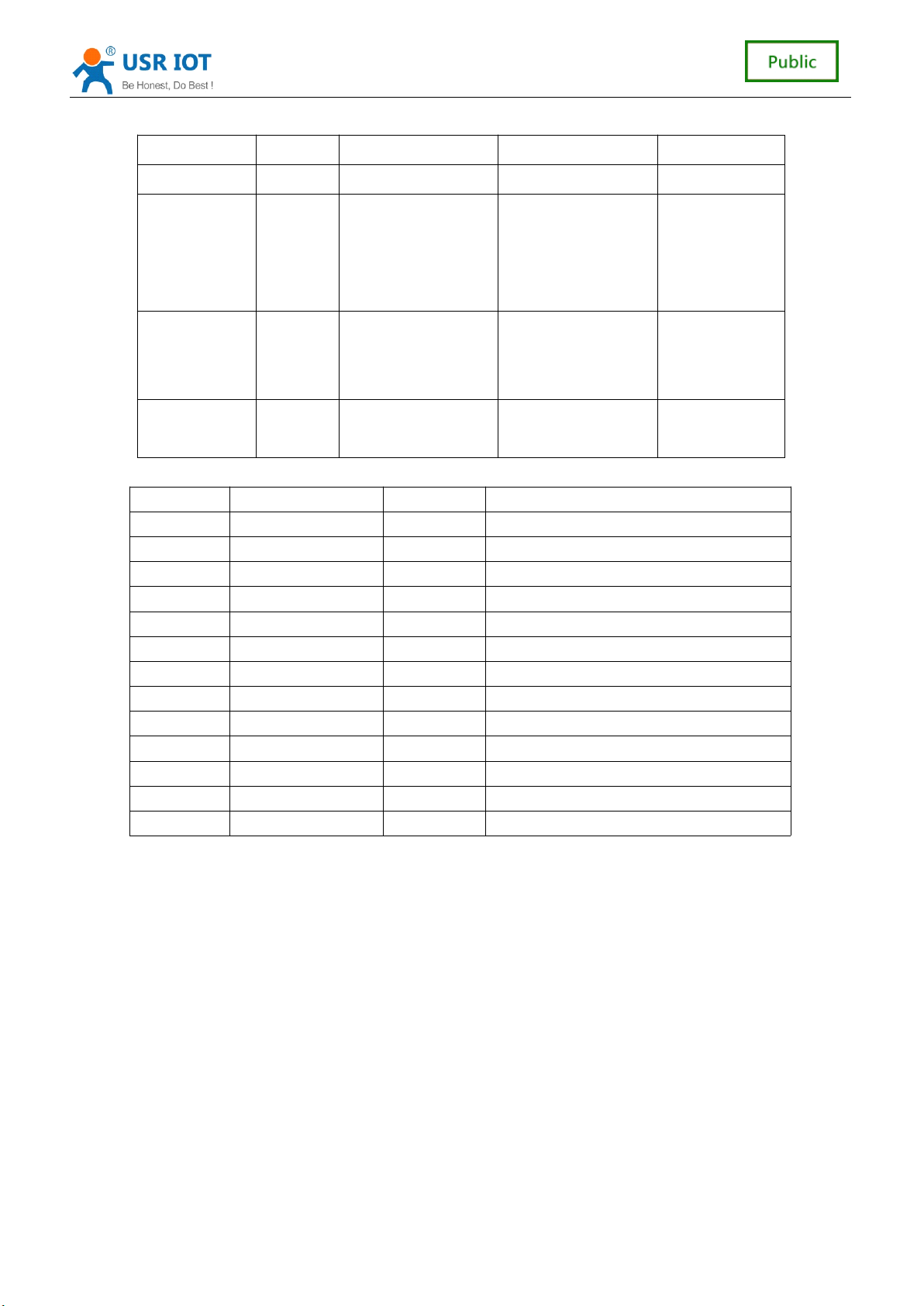
Protocol length is 8 bytes, specific agreement content as follows, for example the value
for the HEX format:
18
41
18
41
18
18 / 41
41
Page 19
USR-C321 Low Power M inisize WiFi Module User Manual www.usr.so
designation Header Bps Data bit Check
length(bytes) 3 3 1 1
reduce
explain
Exam p le
(115200,N,8,
1)
Example
(9600,N,8,1)
Attachment: a serial port parameters meaning a bit
Bit num Explain Data describe
1:0 Data bits 00 5 bits
2 Stop bit 0 1 bit
3 Enabled check 0 Disable check
5:4 Check type 00 ODD
7:6 NC 00 Write 0
misjudg
ment
55 AA
55
55 AA55 00 25 80 83 28
baud rate value,
high in the former
01 C2 00 83 46
01 6 bits
10 7 bits
11 8 bits
1 2 bits
1 Enable check
01 EVEN
10 Mark
11 Clear
Different bits to
represent different
meanings, see
table
Sum of the
front four
3.
10
3.
10
3.
3. 10
10 Sleep
Sleep
Sleep
Sleep Mode
Mode
Mode
Mode Introduction
Introduction
Introduction
Introduction
Modules can open low power mode. In module under normal condition, if the network and
uart port for certain time 10-240 seconds
(AT
+ SLPTYPE Settings) does not data
communication module into low power mode. The user can choose different sleep mode (0 to
4).
Ways there are to awaken the network side and serial port: network side refers to establish
the wifi connection, to establish a socket connection with module and send data to the socket, a
serial port end points to a serial port to send data.
For example: set up
AT
+ SLPTYPE = 2,200
When the module network end (refer to the socket end) and a serial port for 200 seconds
didn't receive the data, the module into Deepsleep mode (mode 2).
19
41
19
41
19
19 / 41
41
Page 20
3.
3.
3.
3. 10
10
.1
Mode
10
.1
Mode
10 .1
.1 Mode
Mode Introduction
Introduction
Introduction
Introduction
USR-C321 Low Power M inisize WiFi Module User Manual www.usr.so
Mode
Mode
Mode
Mode 0:
0:
Active
0:
Active
0: Active
Active Mode
Mode
Mode
Mode
The Active mode, the system clock is 80 MHZ. Module running various peripherals.
Corresponding mode 0, that is, normal work mode, the module optimal performance.
Mode
Mode
Mode
Mode 1:
1:
Sleep
1:
Sleep
1: Sleep
Sleep Mode
Mode
Mode
Mode
Sleep mode, the system clock to 80 MHZ. Through a serial port or network packets,
gpio port output, module after awakening from entering hibernation continues to run, wake
up the response time shorter than deepsleep mode. Corresponding mode 1.
Mode
Mode
Mode
Mode 2:
2:
Deepsleep
2:
Deepsleep
2: Deepsleep
Deepsleep Mode
Mode
Mode
Mode
Module into deepsleep dormancy, reduced to 40 MHZ system clock. Might wake up via
a serial port or network packets, gpio port output, module after awakening from entering
hibernation continues to run, wake up the response time a bit longer than the sleep mode.
Than the normal operation of the lower power consumption about 5 ma. The corresponding
mode 2.
Mode
Mode
Mode
Mode 3:
3:
LPDS
3:
LPDS
3: LPDS
LPDS Mode
Mode
Mode
Mode
Module into LPDS mode, network part keep running, module gpio port output is high
impedance state. Via a serial port or network packets wake up, wake up after the restart
operation module. Corresponding mode 3.
Mode
Mode
Mode
Mode 4:
4:
Hibernate
4:
Hibernate
4: Hibernate
Hibernate Mode
Mode
Mode
Mode
Module into the hibernate mode, network and MCU are entering sleep mode, gpio port
output high impedance state, only through a serial port data. Module after the restart. Power
consumption can be achieved the uA level. Corresponding mode 4.
3.
10
.2
3.
3.
3. 10
Power
10
.2
Power
10 .2
.2 Power
Power Reference
Reference
Reference
Reference Table
Table
Table
Table
No data transmission module, the power consumption mode reference is as follows:
Power
mode
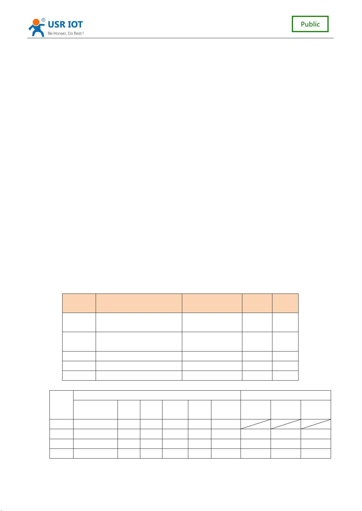
0
1
2 UART 、 network working Uart,network 9 mA 70 mA
3 UART 、 network working Uart,network 3.5 mA 70 mA
4 GPIO ( RXD ) working Uart(RXD) 24 uA 24 uA
UART 、 GPIO 、 network
UART 、 GPIO 、 network
working
UART 、 GPIO 、 network
working
Wake up mode STA AP
none 18 mA 74 mA
Uart,network 13 mA 71 mA
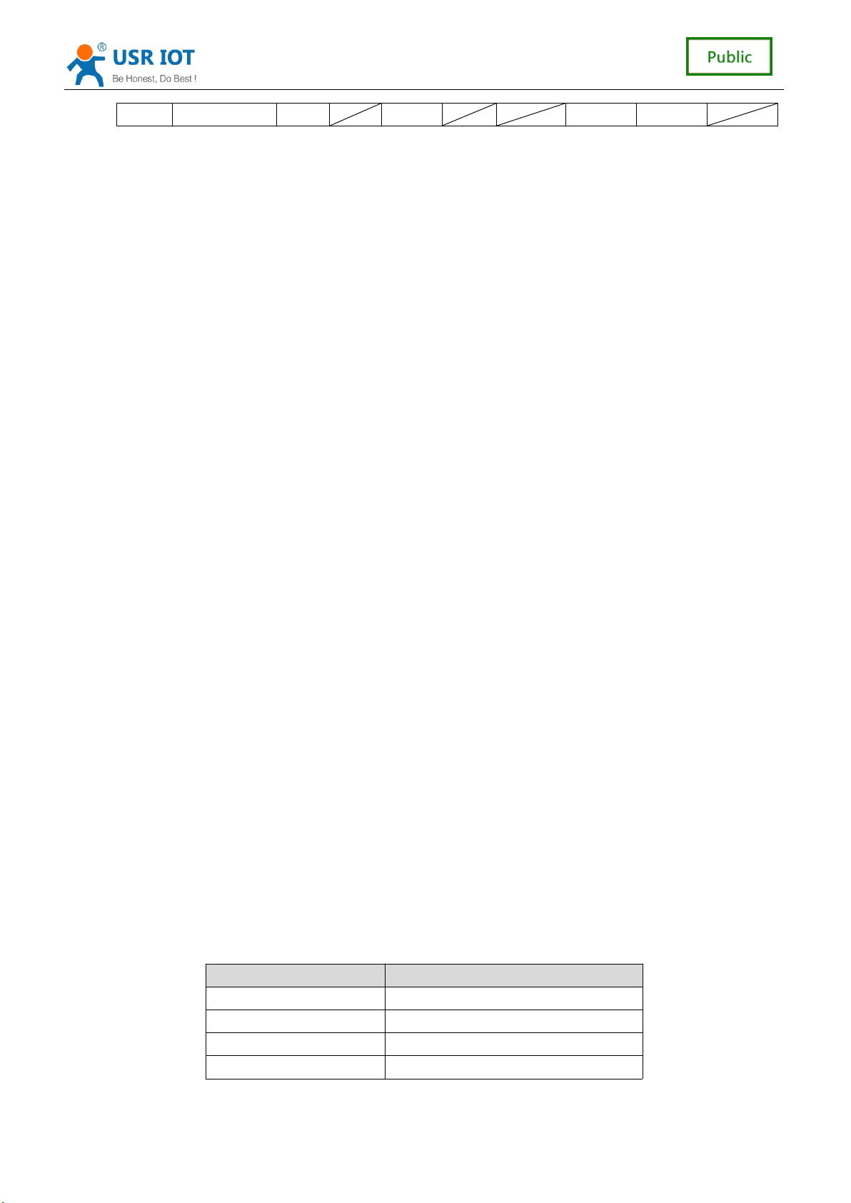
The mode to distinguish the table:
Powe
r
mode
0 80M
1 80M
2 40M
3 32.768Khz
Still working Wakeup source
Run
frequency
MCU WIFI UART GPIO network UART GPIO network
RXD
RXD
RXD
20
20
20
20 / 41
41
41
41
Page 21
USR-C321 Low Power M inisize WiFi Module User Manual www.usr.so
4 32.768Khz
The difference between all modules, low power consumption mode is as follows:
Wake up the response time: from mode 0 to 4, wake up the response time
increases gradually.
Power consumption: from mode 0 to 4, gradually reduce the power consu
mption.
Example: low power consumption
1
Wifi module online, various peripherals work is normal, the data transmission
、
between the interval of a few seconds, use "pattern 1".
2 、 Wifi module online, various peripherals working frequency decline or does not
work, you can use "mode 2" Deepsleep model.
3 、 Module to keep online, can through the remote wireless equipment, occasionally
translate data, suit to use "mode 3" Lpds mode, remote equipment after wake
up the module, the module to establish the connection with the remote device,
sending and receiving data.
4 、 When the user equipment does not need to be online for a long time, only
occasionally arouse initiative to send data to the server, you can use "mode 4"
Hibernate mode. A frame to a serial port to send data, wake up module, the
module will be according to set the wifi, TCP socket parameters, the active link
to the server, translate data, translate is completed according to set the time to
sleep.
<
note
<
<
< note
>
note
>
note >
> : serial awakens the module, in Lpds mode, Hibernate mode, practical for the
RXD pin. So must contain 0 8 bits of data, namely the need to guarantee the
RXD pin has a low level, this packetjust wake up module, data packet loss, not
translate.
RXD RXD RXD
4
、
Parameter
4
、
Parameter
4
4 、
、 Parameter
Parameter Setting
The parameters of the module configuration page configuration,
configuration in two ways, behind will detail the use of two ways.
4.1
Web
4.1
Web
4.1
4.1 Web
Web Page
4.1.1
4.1.1
4.1.1
4.1.1 The
When using the module for the first time, need some configuration on the module. By PC
connection module AP interface, the user can use the web management page configuration.
By default, the module of AP interface SSID, IP address, user name and password are as
follows:
Page
Page
Page Configuration
The
Web
The
Web
The Web
Web Management
Setting
Setting
Setting
Configuration
Configuration
Configuration
Management
Management
Management Page
parameter default setting
SSID USR-C321
IP address 192.168.1.1
mask 255.255.255.0
user name admin
Page
Page
Page
AT
+ command
21
21
21
21 / 41
41
41
41
Page 22
USR-C321 Low Power M inisize WiFi Module User Manual www.usr.so
key admin
4.1.2
Open
4.1.2
Open
4.1.2
4.1.2 Open
Open Management
Management
Management
Management Web
Web
Web
Web Page
Page
Page
Page
Link with PC wireless card first, after waiting for connection is good, open the IE browser, in
the address bar enter 192.168.1.1, carriage return, the login page, the default login as admin,
the password for the admin. Web support switch in both Chinese and English, can through the
web page top right corner "Chinese | English" switch, also can through the at command set.
Then the web management page will appear. Management page including "system state"
and "WiFi parameters" "translate parameters" "additional features" "account management"
"return to restart Settings" "about someone.
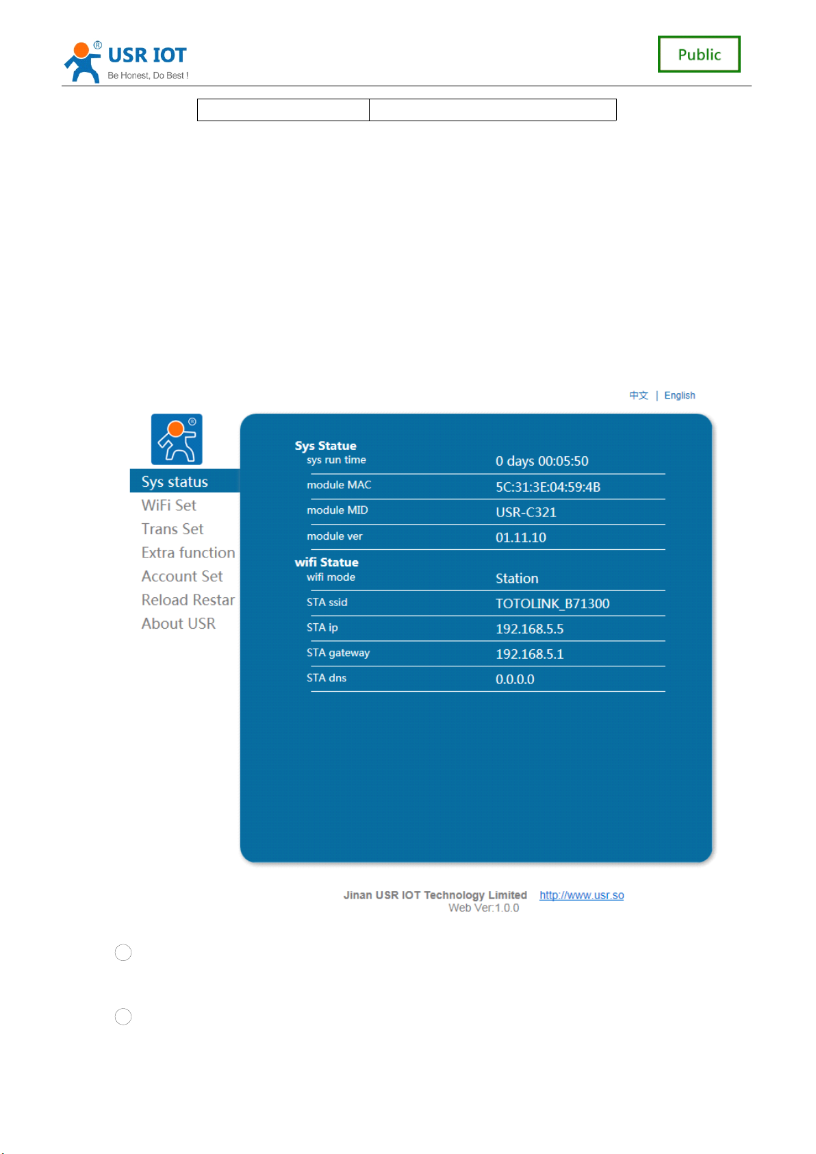
1
The System Status Page
)
Mainly for the module operation parameters, including: MAC address, MID number,
version and WiFi link state.
2
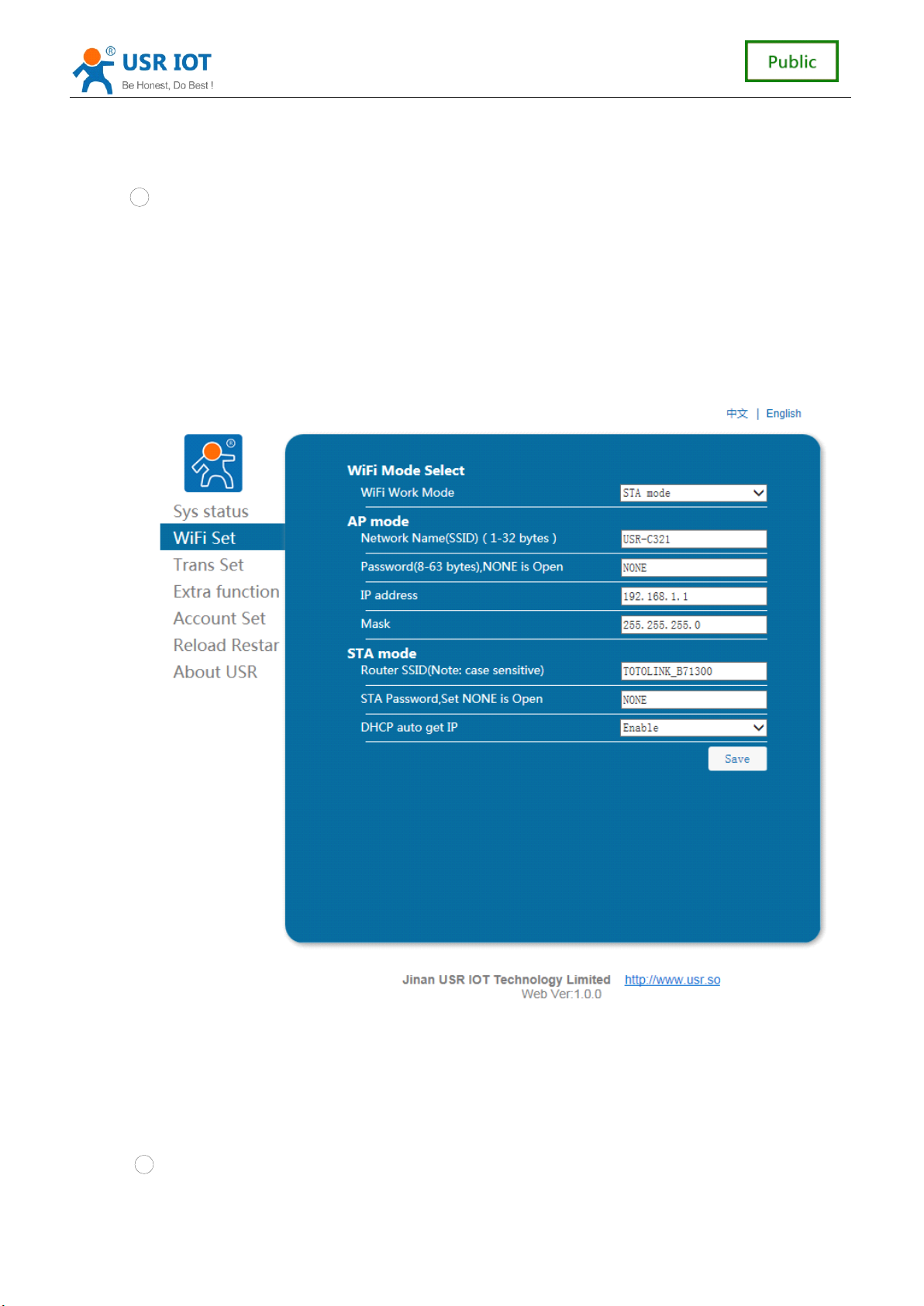
WiFi Parameter Setting:
)
1 Wifi Mode Select:
Wifi model can choose the model of the STA and AP, click save Settings, res
tart to take effect.
2 AP Parameter Setting:
22
22
22
22 / 41
41
41
41
Page 23
USR-C321 Low Power M inisize WiFi Module User Manual www.usr.so
Setting module in AP mode SSID and password (AP mode password for 8-63),
encryption mode is WPA2PSK by default mode, click save Settings, restart to take
effect.
3
STA
Parameter Setting:
Setting module in the
STA
mode needs to connect AP SSID and password (adaptive
encryption module), DHCP is enabled. When the connection of the AP is no encryption,
set the password to none. DHCP automatically obtain IP enabled, the module will
automatically get the
and obtain a static
Note:
Note:
Note:
Note: when the network name and password does not support the double quotes,
IP,
DHCP can ban, through input the
IP,
restart to take effect.
IP,
subnet mask, gateway,
comma, and, or, greater than, less than and other special characters.
3
Trans Setting:
)
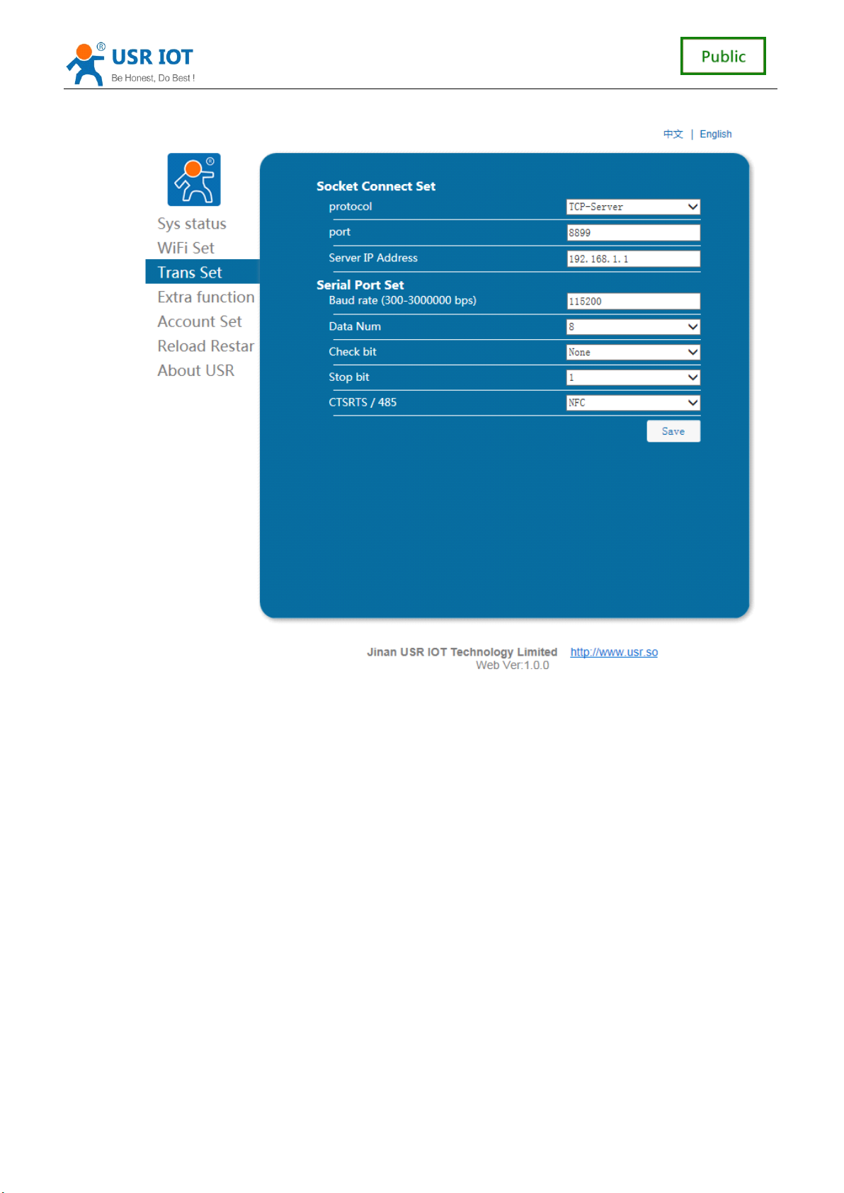
Peripherals parameters set mainly set serial port, serial port baud rate can be set to
300-3000000, data bits can set 5-8 bits, parity bit can be set to no check, odd parity, parity, stop bits
can be set to 1 to 2, a serial port flow control can be set to enabled . Serial port can open 485 features,
pin 25 serial flow control RTS pin i s the control pin of 485 , up the pin to send data, low the pin to receive
data. E ffect ing after restart.
1 Socket set
23
41
23
41
23
23 / 41
41
Page 24
USR-C321 Low Power M inisize WiFi Module User Manual www.usr.so
Transparent transmission mode, the socket protocol, the server address and port.
4
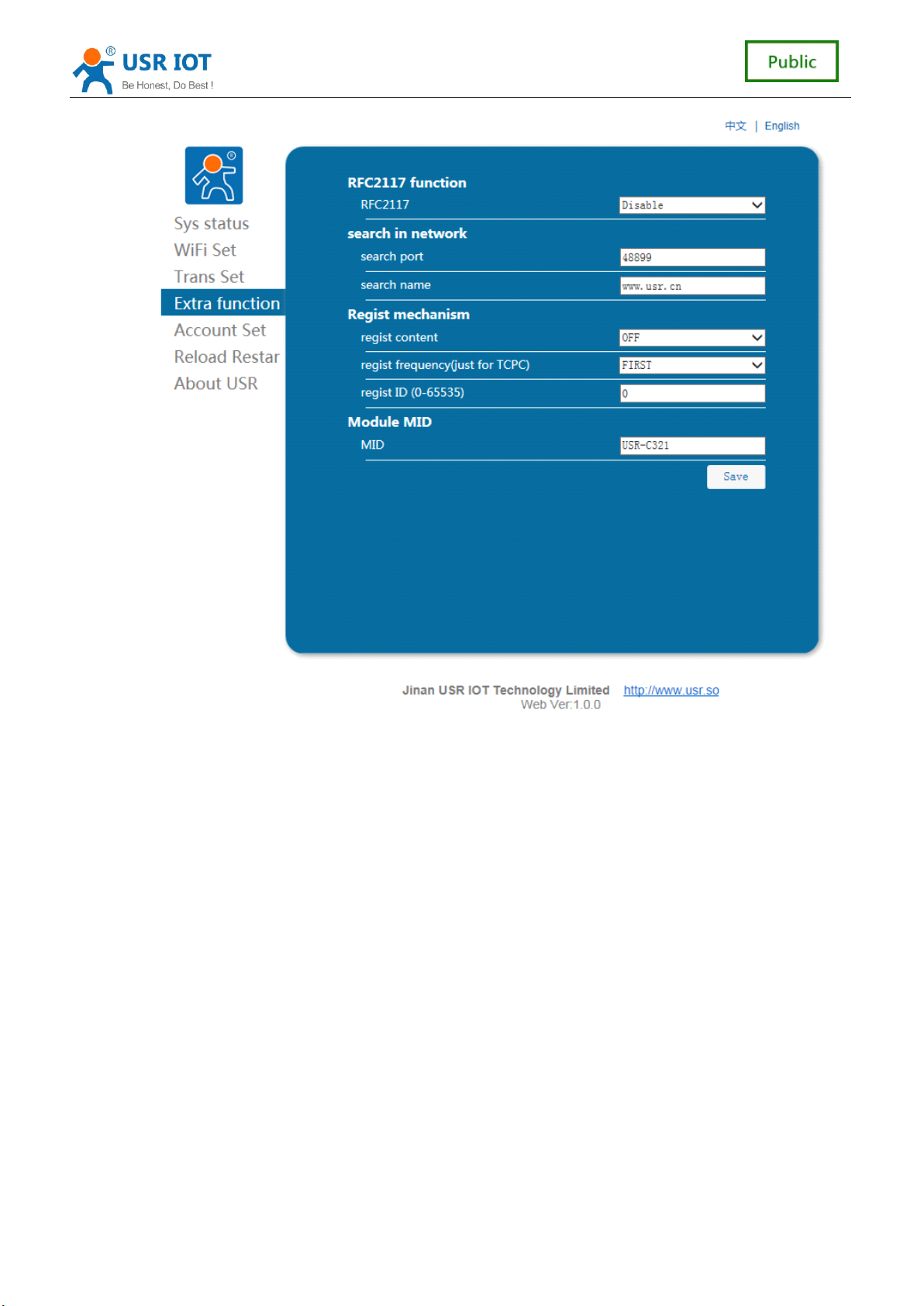
Extra Function
)
Transparent transmission mode, the socket protocol, the server address and port.
24
24
24
24 / 41
41
41
41
Page 25
USR-C321 Low Power M inisize WiFi Module User Manual www.usr.so
5
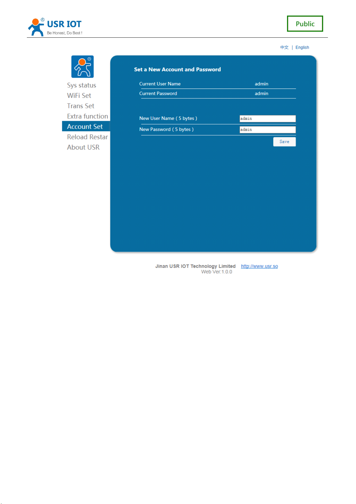
Account Set:
)
Account management can set the user name and password login page, the length
must be 5 bytes , click save Settings, restart to take effect.
25
25
25
25 / 41
41
41
41
Page 26
USR-C321 Low Power M inisize WiFi Module User Manual www.usr.so
6
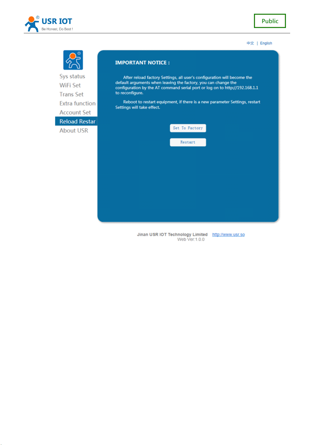
Reload Restar:
)
This page includes the module to the factory state and restart the module function.
26
26
26
26 / 41
41
41
41
Page 27
USR-C321 Low Power M inisize WiFi Module User Manual www.usr.so
7
About USR:
)
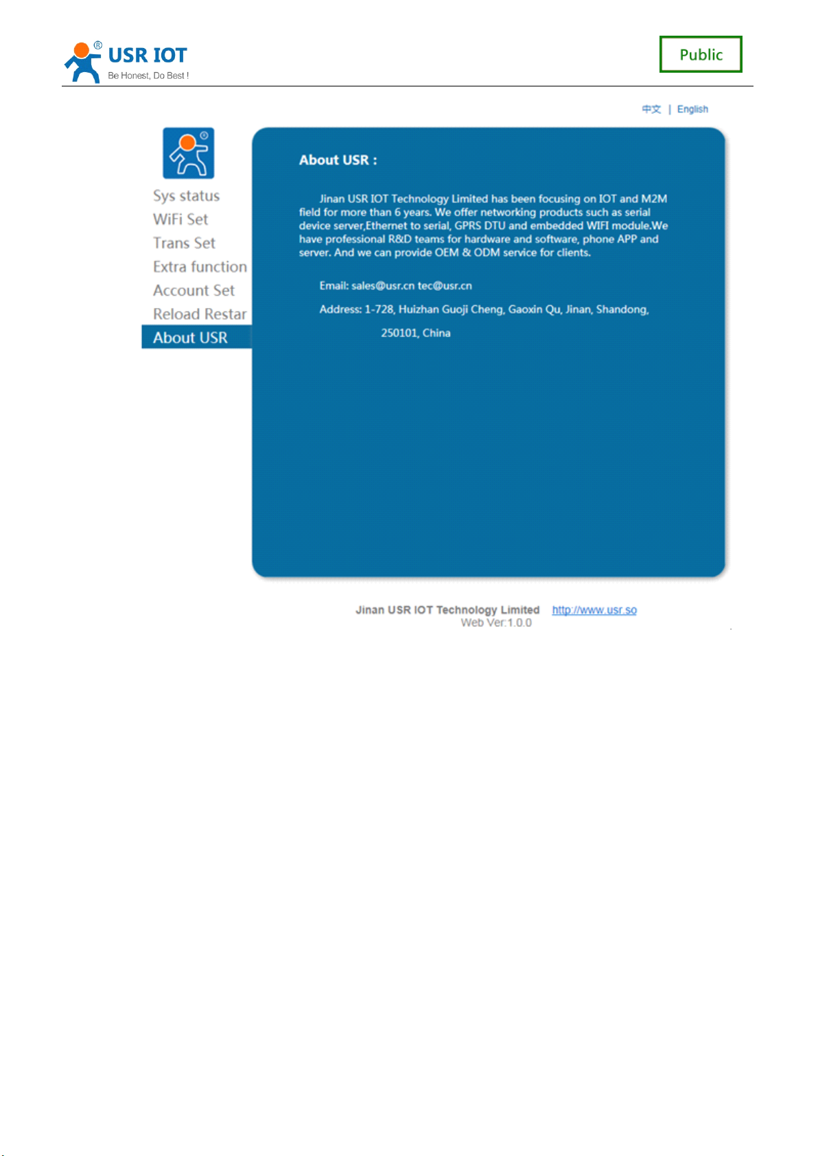
This page is a simple introduction of Jinan USR IOT Technology Limited .
27
27
27
27 / 41
41
41
41
Page 28
USR-C321 Low Power M inisize WiFi Module User Manual www.usr.so
4.2
AT+
4.2
4.2
4.2 AT+
AT+ Instruction refers to
set of instructions, behind will detail the use of
After the success of the electric start, can through the UART for setting module.
Module of the default UART port parameters for: 115200 baud rate, no check, 8 data bits,
one stop bit.
< explain
The
software tools or some professional applications. The following is introduced using UART
communication and SecureCRT tool demo.
From translate mode switch to the command mode to the following two steps:
On the UART input "+ + +", module after receiving "+ + +" will return a verification code
Input validation code "a" on the UART, module after receiving the confirmation, return to
Commands
AT+
Commands
AT+ Commands
Commands Configuration
explain
explain
explain >
AT
command debugging tools, UART interface is recommended to use SecureCRT
"a";
the "+" OK "to confirm, enter the command mode;
Configuration
Configuration
Configuration
in command mode user by module with UART and SPI command
,
AT
+ instruction format.
28
28
28
28 / 41
41
41
41
Page 29

USR-C321 Low Power M inisize WiFi Module User Manual www.usr.so
explain
explain
< explain
explain >In the input "+ + +" and "the code" a ", no echo, as shown in the above.
Input "+ + +" and "a" needs to be done in a certain period of time, in order to reduce the
probability of normal work, wrongly into command mode. Specific requirements are as follows:
From the command mode to switch to translate mode need to adopt the
command, the command
AT
+ ENTM mode input, end with a carriage return, you can switch to
AT
+ ENTM
translate mode.
4.2.1
AT+
4.2.1
4.2.1
4.2.1 AT+
Summary
AT+
Summary
AT+ Summary
Summary of
of
Instruction
of
Instruction
of Instruction
Instruction Set
Set
Set
Set
AT+ Instructions can be directly through the super terminal serial debugger such as input,
can also be programmed to input .
AT+ Instructions the command line, based on ASCII format is as follows :
Format Specification
<
>
<
>
<
< >
> : A part of must contain
[
]
[
]
[
[ ]
] : the optional parts
Command
AT+<CMD>[op][para-1,para-2,para-3,para-4
AT+<CMD>[op][para-1,para-2,para-3,para-4
AT+<CMD>[op][para-1,para-2,para-3,para-4
AT+<CMD>[op][para-1,para-2,para-3,para-4 …
…
]<CR>
…
]<CR>
… ]<CR>
]<CR>
AT+: Command messages prefix ;
CMD: Command string ;
[op] : Instruction operator, is specified parameters to set or query ;
“ = ” : parameter Settings
“ NULL ” : query
[para-n] : Input parameter Settings, such as query is not required ;
<CR>: end mark
<NOTICE>:
<NOTICE>:
<NOTICE>:
<NOTICE>: If
If
,
the
If
the
If the
the user
sent
sent
sent
sent back
ENTER
user
user
user has
back
back
back from
ASCII: 0x0a or 0x0d;
,
has
no
has
has no
from
from
from the
closing
no
closing
no closing
closing echo
the
module,<CR>is
the
module,<CR>is
the module,<CR>is
module,<CR>is not
echo
echo
echo function
function
function
function (AT+E),the
(AT+E),the
(AT+E),the
(AT+E),the command
not
return.
not
return.
not return.
return.
command
command
command will
Response Message
<CR><LF>+<RSP>[op]
<CR><LF>+<RSP>[op]
<CR><LF>+<RSP>[op]
<CR><LF>+<RSP>[op] [para-1,para-2,para-3,para-4
[para-1,para-2,para-3,para-4
[para-1,para-2,para-3,para-4
[para-1,para-2,para-3,para-4 …
…
]<CR><LF>
…
]<CR><LF>
… ]<CR><LF>
]<CR><LF>
+: The response message prefix ;
RSP: Response to a string, including :
“ OK ” :success
“ ERR ” :fail
[para-n] : The query return parameter error code or error
will
will
will be
be
be
be
29
29
29
29 / 41
41
41
41
Page 30
Error Code
4.2.2
AT
4.2.2
AT
4.2.2
4.2.2
AT
AT
USR-C321 Low Power M inisize WiFi Module User Manual www.usr.so
<CR>:ASCII 0x0d;
<LF>:ASCII 0x0a;
Error
Error
Error
Error Code
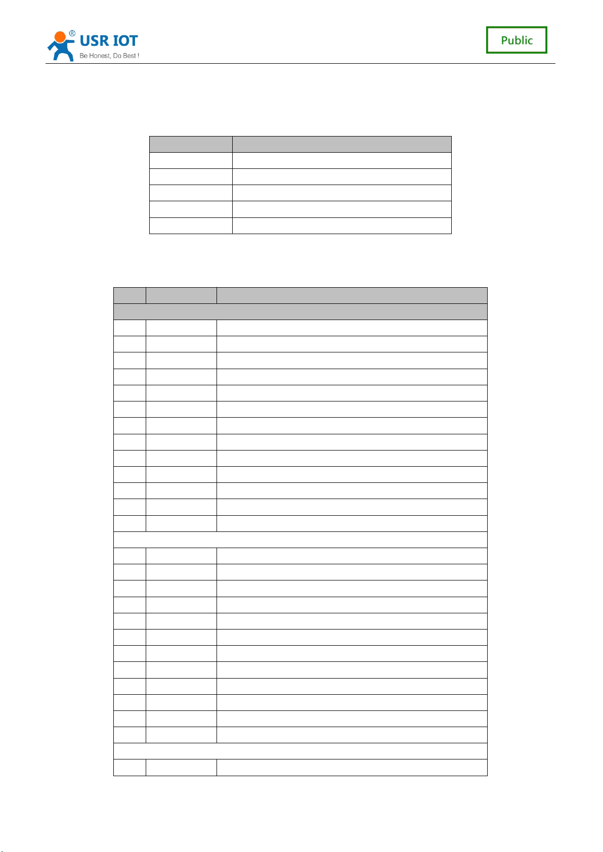
-1 Invalid Command Format
-2 Invalid Command
-3 Invalid Operation Symbol
-4 Invalid Parameter
-5 Operation Not Permitted
Command
Command
Command
Command Introduction
NO
NO
NO
NO Command
Basic Command
1 ENTM Set module into transparent transition mode
2 E Open/Close show back function
3 Z Re-start module
4 CFGTF Copy User Parameters to Factory Default Parameters
5 RELD Restore to factory default setting
6 MAC Read the MAC of module
7 SEARCH Set/query LAN port and keyword search
8 MID Query module ID information
9 PLANG Web log in languages
10 WEBU Set/query website login user name and password
11 VER Query The module firmware version
12 PING Network ” Ping ” command
13 WSCAN Scan AP
Wifi Set
14 WMODE Set/Query Wi-Fi work mode (AP/STA)
15 WSTA Set/query associated AP SSID and password;
16 WANN Set/query STA network parameters;
17 WSLK Query STA Wi-Fi link status
18 WAP Set/query AP wi-fi configuration parameters;
19 CHANNEL Channel module AP mode
20 SOCKA Set/query network protocol parameters
21 LANN Set the IP/query module AP mode
22 SOCKLKA Query whether the TCP link chain has been built
23 REGENA Can make/registration packet mechanism is prohibited
24 REGID Registration packet ID set
25 RFCENA Can make/ban RFC2117 function
Peripheral Parameter Settings
26 UART Set/query UART interface parameters
Introduction
Introduction
Introduction
Command
Command
Command Description
Code
Code
Code Description
Description
Description
Description
Description
Description
Description
error code table
AT+ command
30
30
30
30 / 41
41
41
41
Page 31

USR-C321 Low Power M inisize WiFi Module User Manual www.usr.so
27 UARTTE Set/query a serial port free framing intervals
28 SLPTYPE Set the sleep mode
1) AT+ENTM
Function: Exit the command mode, enter the translate mode;
Format:
Set
AT+ENTM<CR>
AT+ENTM<CR>
AT+ENTM<CR>
AT+ENTM<CR>
<CR><LF>+OK<CR><LF>
<CR><LF>+OK<CR><LF>
<CR><LF>+OK<CR><LF>
<CR><LF>+OK<CR><LF>
Parameters:
无
After the command is executed correctly, module from the command mode switch
to translate mode.
2) AT+E
Function: Set/query module echo the at command set
Format:
Query
AT+E
AT+E
AT+E
AT+E <CR>
<CR><LF>+OK=<on/off><CR><LF>
<CR><LF>+OK=<on/off><CR><LF>
<CR><LF>+OK=<on/off><CR><LF>
<CR><LF>+OK=<on/off><CR><LF>
<CR>
<CR>
<CR>
Set
AT+E=<on/off><CR>
AT+E=<on/off><CR>
AT+E=<on/off><CR>
AT+E=<on/off><CR>
<CR><LF>+OK<CR><LF>
<CR><LF>+OK<CR><LF>
<CR><LF>+OK<CR><LF>
<CR><LF>+OK<CR><LF>
Parameters:
on:Open the echo, echo the AT command input command, off: the AT
command mode, type the command does not echo.
3) AT+Z
Function: Restart the module Format:
Set
AT+Z<CR>
AT+Z<CR>
AT+Z<CR>
AT+Z<CR>
<CR><LF>+OK<CR><LF>
<CR><LF>+OK<CR><LF>
<CR><LF>+OK<CR><LF>
<CR><LF>+OK<CR><LF>
Parameters: none
After the command is executed correctly, restart the module.
4) AT+CFGTF
Function: After the command is executed correctly, restart the module.
Format:
Set
AT+CFGTF<CR>
AT+CFGTF<CR>
AT+CFGTF<CR>
AT+CFGTF<CR>
<CR><LF>+OK=<status><CR><LF>
<CR><LF>+OK=<status><CR><LF>
<CR><LF>+OK=<status><CR><LF>
<CR><LF>+OK=<status><CR><LF>
Parameters:
status:Returns the operating status;
SAVED:Set up the success
NON-SAVED:Setup failed
5) AT+RELD
Function: Recovery module configuration parameters for the user the factory
configuration parameters
Format:
31
31
31
31 / 41
41
41
41
Page 32

USR-C321 Low Power M inisize WiFi Module User Manual www.usr.so
Set
AT+
RELD<CR>
AT+
RELD<CR>
AT+
AT+ RELD<CR>
RELD<CR>
<CR><LF>+OK=REBOOTING
<CR><LF>+OK=REBOOTING
<CR><LF>+OK=REBOOTING
<CR><LF>+OK=REBOOTING …
…
<CR><LF>
…
<CR><LF>
… <CR><LF>
<CR><LF>
Parameters: none
The command module configuration parameters restore to the user factory Settings,
and then restart automatically.
6) AT+MAC
Function: Query MAC
Format:
Query
AT+MAC<CR>
AT+MAC<CR>
AT+MAC<CR>
AT+MAC<CR>
<CR><LF>+OK=<mac><CR><LF>
<CR><LF>+OK=<mac><CR><LF>
<CR><LF>+OK=<mac><CR><LF>
<CR><LF>+OK=<mac><CR><LF>
Parameters:
mac:MAC of the modul ( example 01020304050A ) ;
7) AT+SEARCH
Function: Set/query in LAN port and search module search keywords
Format:
Query
AT+SEARCH<CR>
AT+SEARCH<CR>
AT+SEARCH<CR>
AT+SEARCH<CR>
<CR><LF>+OK=<port,keywords><CR><LF>
<CR><LF>+OK=<port,keywords><CR><LF>
<CR><LF>+OK=<port,keywords><CR><LF>
<CR><LF>+OK=<port,keywords><CR><LF>
Set
AT+
SEARCH
AT+
SEARCH
AT+
AT+ SEARCH
SEARCH <CR>
<CR><LF>+OK
<CR><LF>+OK
<CR><LF>+OK
<CR><LF>+OK =<port,keywords><CR><LF>
<CR>
<CR>
<CR>
=<port,keywords><CR><LF>
=<port,keywords><CR><LF>
=<port,keywords><CR><LF>
Parameters:
port:Search module port;default:48899
keywords:Module search keywords.default:www.usr.cn ( Up to 20 bytes ) .
8) AT+MID
Function: Set the MID/query module
Format:
Query
AT+MID<CR>
AT+MID<CR>
AT+MID<CR>
AT+MID<CR>
<CR><LF>+OK=<mid><CR><LF>
<CR><LF>+OK=<mid><CR><LF>
<CR><LF>+OK=<mid><CR><LF>
<CR><LF>+OK=<mid><CR><LF>
Set
AT+MID=<mid><CR>
AT+MID=<mid><CR>
AT+MID=<mid><CR>
AT+MID=<mid><CR>
<CR><LF>+OK<CR><LF>
<CR><LF>+OK<CR><LF>
<CR><LF>+OK<CR><LF>
<CR><LF>+OK<CR><LF>
Parameters:
mid: Set/query module mids (20 characters), MID the main models of module;
Note: this setting, mid cannot contain a comma ", ".
9) AT+PLANG
Function: Set/query module landing page language version
Format:
Query
AT+
PLANG
AT+
PLANG
AT+
AT+ PLANG
PLANG <CR>
<CR><LF>+OK=<language><CR><LF>
<CR><LF>+OK=<language><CR><LF>
<CR><LF>+OK=<language><CR><LF>
<CR><LF>+OK=<language><CR><LF>
<CR>
<CR>
<CR>
Set
32
32
32
32 / 41
41
41
41
Page 33

USR-C321 Low Power M inisize WiFi Module User Manual www.usr.so
AT+
PLANG
AT+
PLANG
AT+
AT+ PLANG
PLANG =<
<CR><LF>+OK<CR><LF>
<CR><LF>+OK<CR><LF>
<CR><LF>+OK<CR><LF>
<CR><LF>+OK<CR><LF>
=<
language
=<
language
=< language
language ><CR>
><CR>
><CR>
><CR>
Parameters:
language:CN/EN
CN said landing page default display in Chinese; EN said
,
landing page when the default display in English.
10) AT+WEBU
Function: Set/query website login user name and password;
Format:
Query
AT+WEBU<CR>
AT+WEBU<CR>
AT+WEBU<CR>
AT+WEBU<CR>
<CR><LF>+OK=<username,password><CR><LF>
<CR><LF>+OK=<username,password><CR><LF>
<CR><LF>+OK=<username,password><CR><LF>
<CR><LF>+OK=<username,password><CR><LF>
Set
AT+WEBU<CR>=<username,password><CR>
AT+WEBU<CR>=<username,password><CR>
AT+WEBU<CR>=<username,password><CR>
AT+WEBU<CR>=<username,password><CR>
<CR><LF>+OK<CR><LF>
<CR><LF>+OK<CR><LF>
<CR><LF>+OK<CR><LF>
<CR><LF>+OK<CR><LF>
Parameters:
username:The user name, the length must be 5 characters, does not support
null;
password:Password, the length must be 5 characters;
11) AT+VER
Function: Set/query module firmware version
Format:
Query
AT+VER<CR>
AT+VER<CR>
AT+VER<CR>
AT+VER<CR>
<CR><LF>+OK=<ver><CR><LF>
<CR><LF>+OK=<ver><CR><LF>
<CR><LF>+OK=<ver><CR><LF>
<CR><LF>+OK=<ver><CR><LF>
Set
AT+VER=<ver><CR>
AT+VER=<ver><CR>
AT+VER=<ver><CR>
AT+VER=<ver><CR>
<CR><LF>+OK<CR><LF>
<CR><LF>+OK<CR><LF>
<CR><LF>+OK<CR><LF>
<CR><LF>+OK<CR><LF>
Parameters:
ver: Set/query module firmware version:
AA.BB.CC;AA on behalf of the big version, BB on behalf of the minor
version number, Arthur c. CC represents the hardware version
12) AT+PING
Function: Network "Ping" command
Format:
Set
AT+PING=<IP_address><CR>
AT+PING=<IP_address><CR>
AT+PING=<IP_address><CR>
AT+PING=<IP_address><CR>
<CR><LF>+OK=<STA><CR><LF>
<CR><LF>+OK=<STA><CR><LF>
<CR><LF>+OK=<STA><CR><LF>
<CR><LF>+OK=<STA><CR><LF>
Parameters:
IP_address:For IP address 192.168.1.1 or domain name www.usr.so, domain
name up to 64 bytes.
STA:returned value
SUCCESS
TIMEOUT
13) AT+WSCAN
Function:Search AP :
33
33
33
33 / 41
41
41
41
Page 34

USR-C321 Low Power M inisize WiFi Module User Manual www.usr.so
Query
AT+WSCAN<CR>
AT+WSCAN<CR>
AT+WSCAN<CR>
AT+WSCAN<CR>
<CR><LF>+OK=<LF><CR>SSID,BSSID,Security,Indicator<LF><CR><ap_s
<CR><LF>+OK=<LF><CR>SSID,BSSID,Security,Indicator<LF><CR><ap_s
<CR><LF>+OK=<LF><CR>SSID,BSSID,Security,Indicator<LF><CR><ap_s
<CR><LF>+OK=<LF><CR>SSID,BSSID,Security,Indicator<LF><CR><ap_s
ite_1><LF><CR><ap_site_2><LF><CR><ap_site_3><LF><CR>
ite_1><LF><CR><ap_site_2><LF><CR><ap_site_3><LF><CR>
ite_1><LF><CR><ap_site_2><LF><CR><ap_site_3><LF><CR>
ite_1><LF><CR><ap_site_2><LF><CR><ap_site_3><LF><CR> …
N><CR><LF>
N><CR><LF>
N><CR><LF>
N><CR><LF>
Parameters:
SSID:SSID
BSSID: MAC
11:22:33:44:AA:BB
(
)
Security
Indicator RSSI
Note: in the AP mode WSCAN command, response will be slightly slower, if has
established a TCP connection, the connection will be disconnected, need to
restart after the connection is established.
14) AT+WMODE
Function: Set the query wifi working mode
Format:
Query
AT+WMODE<CR>
AT+WMODE<CR>
AT+WMODE<CR>
AT+WMODE<CR>
<CR><LF>+OK=<
<CR><LF>+OK=<
<CR><LF>+OK=<
<CR><LF>+OK=< status
status
status
status ><CR><LF>
><CR><LF>
><CR><LF>
><CR><LF>
Set
AT+WMODE
AT+WMODE
AT+WMODE
AT+WMODE =<
<CR><LF>+OK<CR><LF>
<CR><LF>+OK<CR><LF>
<CR><LF>+OK<CR><LF>
<CR><LF>+OK<CR><LF>
=<
status
=<
status
=< status
status ><CR>
><CR>
><CR>
><CR>
Parameters:
status:
AP:The module in the AP mode
STA:The module in the STA model
15) AT+WSTA
Function: Set/query associated AP SSID and password;
Format:
Query
AT+WSTA<CR>
AT+WSTA<CR>
AT+WSTA<CR>
AT+WSTA<CR>
<CR><LF>+OK=<AP's
<CR><LF>+OK=<AP's
<CR><LF>+OK=<AP's
<CR><LF>+OK=<AP's ssid><key><CR><LF>
ssid><key><CR><LF>
ssid><key><CR><LF>
ssid><key><CR><LF>
Set
AT+
WSTA
AT+
WSTA
AT+
AT+ WSTA
WSTA =<AP's
<CR><LF>+OK<CR><LF>
<CR><LF>+OK<CR><LF>
<CR><LF>+OK<CR><LF>
<CR><LF>+OK<CR><LF>
=<AP's
=<AP's
=<AP's ssid
ssid
ssid
ssid ><key><CR>
><key><CR>
><key><CR>
><key><CR>
Parameters:
AP's ssid:AP SSID (up support 32 bytes);
key: AP password, the default encryption for wpa2psk, no encryption is set to
NONE.
Note: the ssid and key does not support ", "special characters.
16) AT+WANN
Function: Set/query module access to IP (DHCP/STATIC);
Format:
Query
AT+WANN<CR>
AT+WANN<CR>
AT+WANN<CR>
AT+WANN<CR>
…
<ap_site_
…
<ap_site_
… <ap_site_
<ap_site_
34
34
34
34 / 41
41
41
41
Page 35

USR-C321 Low Power M inisize WiFi Module User Manual www.usr.so
<CR><LF>+OK=<mode,address,mask,gateway,dns
<CR><LF>+OK=<mode,address,mask,gateway,dns
<CR><LF>+OK=<mode,address,mask,gateway,dns
<CR><LF>+OK=<mode,address,mask,gateway,dns ><CR><LF>
><CR><LF>
><CR><LF>
><CR><LF>
Set
AT+WANN=<mode,address,mask,gateway,dns
AT+WANN=<mode,address,mask,gateway,dns
AT+WANN=<mode,address,mask,gateway,dns
AT+WANN=<mode,address,mask,gateway,dns ><CR>
<CR><LF>+OK<CR><LF>
<CR><LF>+OK<CR><LF>
<CR><LF>+OK<CR><LF>
<CR><LF>+OK<CR><LF>
><CR>
><CR>
><CR>
Parameters:
mode:Network IP mode
static:static IP
DHCP:dynamic IP
address,mask,gateway
(
DNS are omitted
,
address: IP;
mask:mask;
gateway:gateway
dns:DNS
Note: set the module to get the dynamic IP, just set up AT + WANN = DHCP < CR >
17) AT+WSLK
Function: Query the STA wireless link state;
Format:
Query
AT+
WSLK<CR>
AT+
WSLK<CR>
AT+
AT+ WSLK<CR>
WSLK<CR>
<CR><LF>+OK=<status,rssi><CR><LF>
<CR><LF>+OK=<status,rssi><CR><LF>
<CR><LF>+OK=<status,rssi><CR><LF>
<CR><LF>+OK=<status,rssi><CR><LF>
Parameters:
status
If there is no connection:return “ Disconnected ”
If there is a connection:return “ AP SSID ( AP MAC ) ”
rssi :0-100 , When signal strength is required less than 10 weak signal, when
the data transmission may lose data.
18) AT+WAP
Function: Set/query AP wi-fi configuration parameters;
Format:
Query
AT+WAP<CR>
AT+WAP<CR>
AT+WAP<CR>
AT+WAP<CR>
<CR><LF>+OK=<
<CR><LF>+OK=<
<CR><LF>+OK=<
<CR><LF>+OK=< ssid,key
ssid,key
ssid,key
ssid,key ><CR><LF>
><CR><LF>
><CR><LF>
><CR><LF>
Set
AT+
WAP
AT+
WAP
AT+
AT+ WAP
WAP =<
<CR><LF>+OK<CR><LF>
<CR><LF>+OK<CR><LF>
<CR><LF>+OK<CR><LF>
<CR><LF>+OK<CR><LF>
=<
ssid,key
=<
ssid,key
=< ssid,key
ssid,key ><CR>
><CR>
><CR>
><CR>
Parameters:
ssid:AP SSID;
key:Set the AP encryption password (the default wpa2psk encryption,
password length greater than or equal to 8 bytes), set to None is without
encryption
Note: the ssid and key does not support ", "special characters.
19) AT+CHANNEL
Function: Channel Settings/query module AP mode
Format:
Query
AT+CHANNEL
AT+CHANNEL
AT+CHANNEL
AT+CHANNEL <CR>
<CR>
<CR>
<CR>
)
35
35
35
35 / 41
41
41
41
Page 36

USR-C321 Low Power M inisize WiFi Module User Manual www.usr.so
<CR><LF>+OK=<NUM><CR><LF>
<CR><LF>+OK=<NUM><CR><LF>
<CR><LF>+OK=<NUM><CR><LF>
<CR><LF>+OK=<NUM><CR><LF>
Set
AT+
CHANNEL
AT+
CHANNEL
AT+
AT+ CHANNEL
CHANNEL =<NUM><CR>
<CR><LF>+OK<CR><LF>
<CR><LF>+OK<CR><LF>
<CR><LF>+OK<CR><LF>
<CR><LF>+OK<CR><LF>
=<NUM><CR>
=<NUM><CR>
=<NUM><CR>
Parameters:
NUM:channel 1-11.
20) AT+SOCKA
Function: Set/query network protocol parameters
Format:
Query
AT+SOCKA<CR>
AT+SOCKA<CR>
AT+SOCKA<CR>
AT+SOCKA<CR>
<CR><LF>+OK=<protocol,IP,port
<CR><LF>+OK=<protocol,IP,port
<CR><LF>+OK=<protocol,IP,port
<CR><LF>+OK=<protocol,IP,port ><CR><LF>
Set
AT+SOCKA=<
AT+SOCKA=<
AT+SOCKA=<
AT+SOCKA=< protocol,IP,port
<CR><LF>+OK<CR><LF>
<CR><LF>+OK<CR><LF>
<CR><LF>+OK<CR><LF>
<CR><LF>+OK<CR><LF>
protocol,IP,port
protocol,IP,port
protocol,IP,port ><CR>
Parameters:
Protocol:Protocol type, including
TCPS TCP server
TCPC TCP client
UDPS UDP server
UDPC UDP client
IP:When the module is set to "CLIENT", the IP address of the server
Port: Protocol port, decimal number, less than 65535
21) AT+LANN
Function: Set the IP query AP mode;
Format:
Query
AT+LANN<CR>
AT+LANN<CR>
AT+LANN<CR>
AT+LANN<CR>
<CR><LF>+OK=<IP,MASK><CR><LF>
<CR><LF>+OK=<IP,MASK><CR><LF>
<CR><LF>+OK=<IP,MASK><CR><LF>
<CR><LF>+OK=<IP,MASK><CR><LF>
Set
AT+
LANN
AT+
LANN
AT+
AT+ LANN
LANN =<IP,MASK><CR>
<CR><LF>+OK<CR><LF>
<CR><LF>+OK<CR><LF>
<CR><LF>+OK<CR><LF>
<CR><LF>+OK<CR><LF>
=<IP,MASK><CR>
=<IP,MASK><CR>
=<IP,MASK><CR>
Parameters:
IP: ip
MASK:mask
22) AT+SOCKLKA
Function: Query the TCP link is established;
Format:
AT+
SOCKLKA<CR>
AT+
SOCKLKA<CR>
AT+
AT+ SOCKLKA<CR>
SOCKLKA<CR>
<CR><LF>+OK=<STA><CR><LF>
<CR><LF>+OK=<STA><CR><LF>
<CR><LF>+OK=<STA><CR><LF>
<CR><LF>+OK=<STA><CR><LF>
Parameters
STA: showing if the TCP link is established
CONNECT: TCP connected
DISCONNECTED: TCP Disconnected
23) AT+REGENA
><CR><LF>
><CR><LF>
><CR><LF>
><CR>
><CR>
><CR>
36
36
36
36 / 41
41
41
41
Page 37

USR-C321 Low Power M inisize WiFi Module User Manual www.usr.so
Function: Set the query registration packet mechanism
Format:
Query
AT+REGENA<CR>
AT+REGENA<CR>
AT+REGENA<CR>
AT+REGENA<CR>
<CR><LF>+OK=<
<CR><LF>+OK=<
<CR><LF>+OK=<
<CR><LF>+OK=< status
status
status
status
method><CR><LF>
method><CR><LF>
method><CR><LF>
method><CR><LF>
,
Set
AT+REGENA
AT+REGENA
AT+REGENA
AT+REGENA =<
<CR><LF>+OK<CR><LF>
<CR><LF>+OK<CR><LF>
<CR><LF>+OK<CR><LF>
<CR><LF>+OK<CR><LF>
=<
status
=<
status
=< status
status
method
method
method
method ><CR>
,
Parameters:
status:
ID:packet mechanism can make can make the registration, the registry
packet ID is 2 bytes
MAC:packet mechanism can make can make the registration, the registry
packet is 6 bytes MAC
OFF:Ban can register packet mechanism
method
EVERY Increase registered before each packet of data packet
FIRST Only link to the server sends a registered packet for the first time
24) AT+REGID
Function: Set the query registration packet ID
Format:
Query
AT+REGID<CR>
AT+REGID<CR>
AT+REGID<CR>
AT+REGID<CR>
<CR><LF>+OK=<
<CR><LF>+OK=<
<CR><LF>+OK=<
<CR><LF>+OK=< NUM><CR><LF>
NUM><CR><LF>
NUM><CR><LF>
NUM><CR><LF>
Set
AT+REGID
AT+REGID
AT+REGID
AT+REGID =<NUM
<CR><LF>+OK<CR><LF>
<CR><LF>+OK<CR><LF>
<CR><LF>+OK<CR><LF>
<CR><LF>+OK<CR><LF>
=<NUM
=<NUM
=<NUM ><CR>
><CR>
><CR>
><CR>
Parameters:
NUM:0-6553 5 , Decimal Format, when selecting registration packet ID, it is
mainly used for the D2D software of our company.
25) AT+RFCENA
Function: Enable/Disable RFC2217 Function
Format:
Query
AT+RFCENA<CR>
AT+RFCENA<CR>
AT+RFCENA<CR>
AT+RFCENA<CR>
<CR><LF>+OK=<
<CR><LF>+OK=<
<CR><LF>+OK=<
<CR><LF>+OK=< status<CR><LF>
status<CR><LF>
status<CR><LF>
status<CR><LF>
Set
AT+RFCENA
AT+RFCENA
AT+RFCENA
AT+RFCENA =<
<CR><LF>+OK<CR><LF>
<CR><LF>+OK<CR><LF>
<CR><LF>+OK<CR><LF>
<CR><LF>+OK<CR><LF>
=<
status><CR>
=<
status><CR>
=< status><CR>
status><CR>
Parameters:
status:
ON:Enable RFC2217 Function
OFF:Disable RFC2217 Function
26) AT+UART
Function: Set/query UART interface parameters
><CR>
><CR>
><CR>
37
37
37
37 / 41
41
41
41
Page 38

USR-C321 Low Power M inisize WiFi Module User Manual www.usr.so
Format:
Query :
AT+UART<CR>
AT+UART<CR>
AT+UART<CR>
AT+UART<CR>
<CR><LF>+OK=<baudrate,data_bits,stop_bit,parity,flowctrl><CR><LF>
<CR><LF>+OK=<baudrate,data_bits,stop_bit,parity,flowctrl><CR><LF>
<CR><LF>+OK=<baudrate,data_bits,stop_bit,parity,flowctrl><CR><LF>
<CR><LF>+OK=<baudrate,data_bits,stop_bit,parity,flowctrl><CR><LF>
Set:
AT+UART=<baudrate,data_bits,stop_bit,parity,flowctrl><CR>
AT+UART=<baudrate,data_bits,stop_bit,parity,flowctrl><CR>
AT+UART=<baudrate,data_bits,stop_bit,parity,flowctrl><CR>
AT+UART=<baudrate,data_bits,stop_bit,parity,flowctrl><CR>
<CR><LF>+OK<CR><LF>
<CR><LF>+OK<CR><LF>
<CR><LF>+OK<CR><LF>
<CR><LF>+OK<CR><LF>
Parameters:
baudrate:
300-3000000 bit/s,
data_bits:5 – 8 bits
stop_bits:1,2
parity: check
NONE
EVEN
ODD
Mask
Space
flowctrl:CTS RTS
NFC:Disable hardware flow control
FC:Enable hardware flow control
485
485 communications, UART_RTS as 485 send control terminal
:
Note: when the baud rate are subject to change, will automatically change the
packaging interval, see 27) AT + UARTTE.
27) AT+UARTTE
Function: Set/query free framing intervals
Format:
Query
AT+
UARTTE<CR>
AT+
UARTTE<CR>
AT+
AT+ UARTTE<CR>
UARTTE<CR>
<CR><LF>+OK=<num><CR><LF>
<CR><LF>+OK=<num><CR><LF>
<CR><LF>+OK=<num><CR><LF>
<CR><LF>+OK=<num><CR><LF>
Set
AT+
UARTTE=<num
AT+
UARTTE=<num
AT+
AT+ UARTTE=<num
UARTTE=<num ><CR>
<CR><LF>+OK<CR><LF>
<CR><LF>+OK<CR><LF>
<CR><LF>+OK<CR><LF>
<CR><LF>+OK<CR><LF>
><CR>
><CR>
><CR>
Parameters:
num:5-250: Free framing mode the interval between two bytes ms.
Note: this parameter will automatically change when set the baud rate, If you want to
change the packaging interval, please first set the baud rate:
bps <= 600 , num=250ms;
bps >= 20000 , num=5ms;
500 < bps < 20000 , num=1000/bps*10*10.
28) AT+SLPTYPE
Function: Set the query sleep mode
Format:
Query
AT+
SLPTYPE<CR>
AT+
SLPTYPE<CR>
AT+
AT+ SLPTYPE<CR>
SLPTYPE<CR>
38
38
38
38 / 41
41
41
41
Page 39

USR-C321 Low Power M inisize WiFi Module User Manual www.usr.so
<CR><LF>+OK=<MODE,TIME><CR><LF>
<CR><LF>+OK=<MODE,TIME><CR><LF>
<CR><LF>+OK=<MODE,TIME><CR><LF>
<CR><LF>+OK=<MODE,TIME><CR><LF>
Set
AT+
SLPTYPE=<MODE,TIME><CR>
AT+
SLPTYPE=<MODE,TIME><CR>
AT+
AT+ SLPTYPE=<MODE,TIME><CR>
SLPTYPE=<MODE,TIME><CR>
<CR><LF>+OK<CR><LF>
<CR><LF>+OK<CR><LF>
<CR><LF>+OK<CR><LF>
<CR><LF>+OK<CR><LF>
Parameters:
MODE:0-4;
0 no sleep mode for setting module (default); 1 set the module to sleep
mode; 2 set the module to deepsleep mode; 3 set the module to LPDS
mode; 4 set the module to deep sleep mode;
TIME:10-240 seconds.
Set the module without communication last time. When last time no
data transmission module, enter the sleep mode, according to the mode
patterns into different dormancy.
Note: when set to no sleep, only set AT
AT
+
AT
+
AT +
+ SLPTYPE
SLPTYPE
SLPTYPE
SLPTYPE =
=
0
<
CR
=
0
<
= 0
0 <
< CR
CR
CR >
>
>
>
39
39
39
39 / 41
41
41
41
Page 40
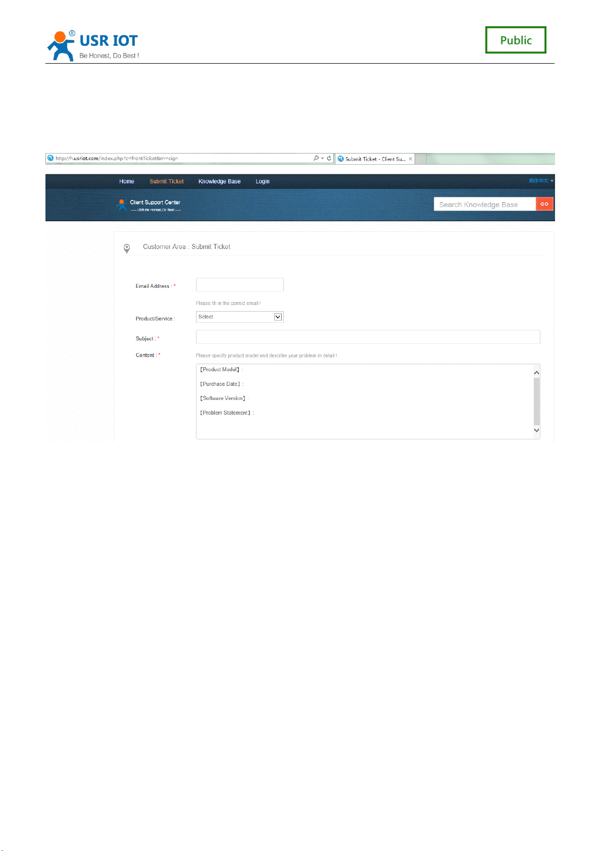
USR-C321 Low Power M inisize WiFi Module User Manual www.usr.so
5
、
service
5
、
service
5
5 、
、 service
service and
If you have problems when use the module,you can submit the question to
http://h.usriot.com
http://h.usriot.com
http://h.usriot.com
http://h.usriot.com .We will solve your question at the first time .
and
and
and support
support
support
support
40
40
40
40 / 41
41
41
41
Page 41

USR-C321 Low Power M inisize WiFi Module User Manual www.usr.so
Appendix A: Contact Information
-----------------------------------------------------------------------------------
-----------------------------------------------------------------------------------
-----------------------------------------------------------------------------------
-----------------------------------------------------------------------------------
Company: Jinan USR IOT Technology Limited
Address: 11th Floor,No.1 Building, Aosheng Square,No.1166 Xinluo Street, Jinan,China
Tel:
Web: http://www.usriot.com
Support : http://h.usriot.com
86-531-55507297, 86-531-88826739
http://www.usriot.com
http://www.usriot.com
http://www.usriot.com
http://h.usriot.com
http://h.usriot.com
http://h.usriot.com
Email: [email protected]
-----------------------------------------------------------------------------------
-----------------------------------------------------------------------------------
-----------------------------------------------------------------------------------
-----------------------------------------------------------------------------------
Appendix B: Disclaimer
This document provides information about USR-C321 modules, this document does not
grant any license to intellectual property rights. Except the responsibility declared in the
product sale clause, USR does not assume any other responsibilities. In addition, USR
does not make any warranties for the sale and use of this product, including the suitability of
the product for a particular purpose, merchantability or fitness for any patent, copyright or
other intellectual property infringement, etc. USR may make changes to specifications and
product descriptions without notice.
Appendix C : Update History
V 1 . 0 14 - 05 -201 5 . First Version
V 1 . 1 28 - 0 7 -201 5 . Change company address.
<END>
<END>
<END>
<END>
41
41
41
41 / 41
41
41
41
 Loading...