

Page 1
INSTALLATION AND
OPERATION MANUAL
“THE SUMMIT” ELECTRIC
CONVECTION OVEN
FOR YOUR SAFETY:
DO NOT STORE OR USE GASOLINE
OR OTHER FLAMMABLE VAPORS OR
LIQUIDS IN THE VICINITY OF
THIS OR ANY OTHER
APPLIANCE
PLEASE READ ALL SECTIONS OF THIS MANUAL
AND RETAIN FOR FUTURE REFERENCE.
THIS PRODUCT HAS BEEN CERTIFIED AS
COMMERCIAL COOKING EQUIPMENT AND
MUST BE INSTALLED BY PROFESSIONAL
PERSONNEL AS SPECIFIED.
WARNING:
IMPROPER INSTALLATION, ADJUSTMENT,
ALTERATION, SERVICE OR MAINTENANCE
CAN CAUSE PROPERTY DAMAGE, INJURY,
OR DEATH. READ THE INSTALLATION,
OPERATING AND MAINTENANCE
INSTRUCTIONS THOROUGHLY
BEFORE INSTALLING OR
SERVICING THIS EQUIPMENT
INSTALLATION AND ELECTRICAL CONNECTION
MUST COMPLY WITH CURRENT CODES:
IN CANADA - THE CANADIAN ELECTRICAL
CODE PART 1 AND / OR LOCAL CODES.
IN USA – THE NATIONAL ELECTRICAL CODE
ANSI / NFPA – CURRENT EDITION.
ENSURE ELECTRICAL SUPPLY CONFORMS WITH
ELECTRICAL CHARACTERISTICS SHOWN ON
THE RATING PLATE.
Users are cautioned that maintenance and repairs must be performed by a Garland authorized service agent
using genuine Garland replacement parts. Garland will have no obligation with respect to any product that has been
improperly installed, adjusted, operated or not maintained in accordance with national and local codes or installation
instructions provided with the product, or any product that has its serial number defaced, obliterated or removed,
or which has been modified or repaired using unauthorized parts or by unauthorized service agents.
For a list of authorized service agents, please refer to the Garland web site at http://www.garland-group.com.
The information contained herein, (including design and parts specifications), may be superseded and is subject
to change without notice.
GARLAND COMMERCIAL INDUSTRIES, LLC
185 East South Street
Freeland, Pennsylvania 18224
Phone: (570) 636-1000
Fax: (570) 636-3903
GARLAND COMMERCIAL RANGES, LTD.
1177 Kamato Road, Mississauga, Ontario L4W 1X4
CANADA
Phone: 905-624-0260
Fax: 905-624-5669
Enodis UK LTD.
Swallow eld Way, Hayes, Middlesex UB3 1DQ ENGLAND
Telephone: 081-561-0433
Fax: 081-848-0041
Part # 1955204 Rev 1 (01/08/09) © 2004 Garland Commercial Industries, LLC
Part # 1955204 Rev 1 (01/08/09) Page 1
Page 2

IMPORTANT INFORMATION
WARNING:
This product contains chemicals known to the state of California to cause cancer and/or birth defects
or other reproductive harm. Installation and servicing of this product could expose you to airborne
particles of glass wool/ceramic fibers. Inhalation of airborne particles of glass wool/ceramic fibers
is known to the state of California to cause cancer.
Keep appliance area free and clear of combustibles.
Part # 1955204 Rev 1 (01/08/09)Page 2
Page 3

TABLE OF CONTENTS
IMPORTANT INFORMATION .............2
DIMENSIONS AND SPECIFICATIONS,
MODEL SUME 100/200 .................4
DIMENSIONS AND SPECIFICATIONS,
MODEL SEM 100/200...................5
INTRODUCTION........................6
Rating Plate ..................................6
INSTALLATION .........................6
Clearances ...................................6
Installation Of Ovens Equipped With Casters . . 6
Installation of Double Deck Models ...........6
Electrical Connections ........................7
Power Failure . . . . . . . . . . . . . . . . . . . . . . . . . . . . . . . . 7
Summit 45 Electronic Control
With Cook-N-Hold And
Summit 45+ Electronic Control
With Cook-N-Hold & Core Probe ..............9
In O Mode .............................. 9
On Start Up .............................. 9
Controller Keys ........................... 9
Fahrenheit/Celsius....................... 10
Operating the Controls ..................10
Cook-N-Hold Operation ................. 11
Core Probe Operation ................... 11
Setting Setback Feature ................. 11
PERFORMANCE RECOMMENDATIONS ..12
PROBLEM/SOLUTIONS ................13
COOKING GUIDE ......................14
OPERATING INSTRUCTIONS.............8
Summit 20 Solid State Control with
Electromechanical Timer . . . . . . . . . . . . . . . . . . . . . 8
In O Mode .............................. 8
Start Up.................................. 8
Fan Speed ............................... 8
Lights .................................... 8
Cool Down............................... 8
Temperature ............................. 8
Timer .................................... 9
COOK AND HOLD .....................15
CLEANING AND MAINTENANCE ........16
Break-In Period . . . . . . . . . . . . . . . . . . . . . . . . . . . . . 16
Exterior Cleaning . . . . . . . . . . . . . . . . . . . . . . . . . . . 16
Interior Cleaning ............................16
Fan Area Maintenance . . . . . . . . . . . . . . . . . . . . . . 16
Motor Care . . . . . . . . . . . . . . . . . . . . . . . . . . . . . . . . . 16
Part # 1955204 Rev 1 (01/08/09) Page 3
Page 4
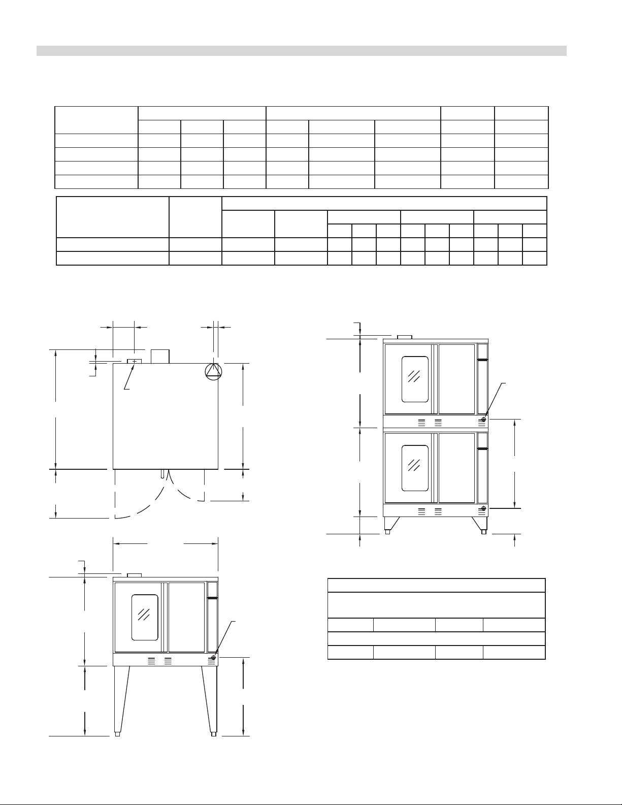
DIMENSIONS AND SPECIFICATIONS, MODEL SUME 100/200
7-3/4"
[197mm]
38-1/4"
[972mm]
3/4"
[19mm]
17-3/4"
[451mm]
38"
[965mm]
32-1/8"
[816mm]
25-3/8"
[645mm]
1-1/4"
[32mm]
32-1/8"
[816mm]
32-1/8"
[816mm]
6-1/4"
[159mm]
1-1/4"
[32mm]
11-1/2"
[292mm]
9-1/4"
[235mm]
32-1/8"
[816mm]
1-11/16"
[43mm]
28-3/8"
[721mm]
FLUE: 2-3/8" x 5"
[60mm x 127mm]
TOP VIEW
DOUBLE DECK
FRONT VIEW
SINGLE DECK
FRONT VIEW
"D" (includes
motor)
REAR CABLE
ENTRANCE
REAR CABLE
ENTRANCE
Model
Int. Dimensions :In (mm) Ext. Dimensions: In (mm) Ship Wt Ship Dim.
W H D W H D Lbs/kg Cubic Ft.
SUME-100S1 29 (736) 24 (610) 24 (610) 38 (965) 57-1/2 (1461) 39-1/4(997) 510/232 42
SUME-100D1 29 (736) 24 (610) 28 (711) 38 (965) 57-1/2 (1461) 43-1/4(1099) 510/232 42
SUME-200S1 29(736) 24(610) 24(610) 38(965) 70-1/2 (1791) 39-1/4(997) 1024/464 84
SUME-200D1 29(736) 24(610) 28 (711) 38(965) 70-1/2 (1791) 43-1/4(1099) 1024/464 84
Nominal Amperes Per Line, (includes 3/4 HP fan motor)
Model Tota kW
208V/1Ph 240V/IPh
208V/3Ph 240V/3Ph 460V/3Ph
X Y Z X Y Z X Y Z
Single Deck 10.4 50 43 30 30 28 26 26 24 14 14 13
Double Deck* each oven 10.4 50 43 30 30 28 26 26 24 14 14 13
* Double Deck Models are provided with individual power supply connections.
Electrical specications include motor requirements. 3/4, HP, 2-speed motor: 1725/1140 rpm, (60Hz); or 1440/950 rpm (50Hz)
Please specify electrical characteristics when ordering.
Instillation Notes:
CombustIble & Non-Combustible
Wall Clearances:
Sides 1" (25mm) Back 3" (76mm)
Entry Clearances: In (mm)
Crated 44-1/2 (1130) Uncrated 32-1/2 (826)
Many local codes exist and it is the responsibility of the
owner and installer to comply with those codes.
These appliances are intended for commercial use by
professionally trained personnel.
Part # 1955204 Rev 1 (01/08/09)Page 4
Page 5
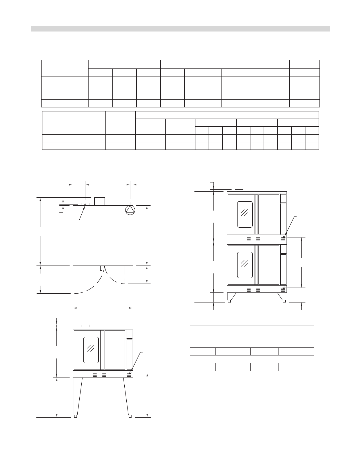
DIMENSIONS AND SPECIFICATIONS, MODEL SEM 100/200
7-3/4"
[197mm]
38-1/4"
[972mm]
3/4"
[19mm]
17-3/4"
[451mm]
38"
[965mm]
32-1/8"
[816mm]
25-3/8"
[645mm]
1-1/4"
[32mm]
32-1/8"
[816mm]
32-1/8"
[816mm]
6-1/4"
[159mm]
1-1/4"
[32mm]
11-1/2"
[292mm]
9-1/4"
[235mm]
32-1/8"
[816mm]
1-11/16"
[43mm]
28-3/8"
[721mm]
FLUE: 2-3/8" x 5"
[60mm x 127mm]
TOP VIEW
DOUBLE DECK
FRONT VIEW
SINGLE DECK
FRONT VIEW
"D" (includes
motor)
REAR CABLE
ENTRANCE
REAR CABLE
ENTRANCE
Model
Int. Dimensions :In (mm) Ext. Dimensions: In (mm) Ship Wt Ship Dim.
W H D W H D Lbs/kg Cubic Ft.
SEM-100S1 29 (736) 24 (610) 24 (610) 38 (965) 57-1/2 (1461) 39-1/4(997) 510/232 42
SEM-100D1 29 (736) 24 (610) 28 (711) 38 (965) 57-1/2 (1461) 43-1/4(1099) 510/232 42
SEM-200S1 29(736) 24(610) 24(610) 38(965) 70-1/2 (1791) 39-1/4(997) 1024/464 84
SEM-200D1 29(736) 24(610) 28 (711) 38(965) 70-1/2 (1791) 43-1/4(1099) 1024/464 84
Nominal Amperes Per Line, (includes 3/4 HP fan motor)
Model Tota kW
208V/1Ph 240V/IPh
208V/3Ph 240V/3Ph 460V/3Ph
X Y Z X Y Z X Y Z
Single Deck 10.4 50 43 30 30 28 26 26 24 14 14 13
Double Deck* each oven 10.4 50 43 30 30 28 26 26 24 14 14 13
* Double Deck Models are provided with individual power supply connections.
Electrical specications include motor requirements. 3/4, HP, 2-speed motor: 1725/1140 rpm, (60Hz); or 1440/950 rpm (50Hz)
Please specify electrical characteristics when ordering.
Instillation Notes:
CombustIble & Non-Combustible
Wall Clearances:
Sides 1" (25mm) Back 3" (76mm)
Entry Clearances: In (mm)
Crated 44-1/2 (1130) Uncrated 32-1/2 (826)
Many local codes exist and it is the responsibility of
the owner and installer to comply with those codes.
These appliances are intended for commercial use by
professionally trained personnel.
Part # 1955204 Rev 1 (01/08/09) Page 5
Page 6

INTRODUCTION
Like any other ne, precision built appliance, your oven
should be given regular care and maintenance. Periodic
inspections by your dealer or a qualied service agency is
recommended.
INSTALLATION
Clearances
Combustible and non-combustible wall clearances are: side,
1.0” (25mm) and rear, 3.0” (76mm).
NOTE: Adequate clearance must be provided for servicing
and proper operation.
Installation Of Ovens Equipped
With Casters
A. For an appliance equipped with casters, the installation
shall be made with a connector that complies with the
Standard for connectors for Movable Appliances, ANSI
Z21.69. Adequate means must be provided to limit the
movement of the appliance without depending on
connector wiring.
B. The front casters of the unit are equipped with brakes to
limit the movement of the oven without depending on
the connector wiring to limit the appliance movement.
C. The restraint can be attached to the unit near the
electrical inlet. If the restraint is disconnected, be sure to
reconnect the restraint after the oven has been returned
to its originally installed position.
Rating Plate
When corresponding with the factory or your local
authorized factory service center regarding service problems
or replacement parts, be sure to refer to the particular unit
by the correct model number (including the prex and sux
letters and numbers) and the warranty serial number. The
rating plate located behind the lower front panel (below the
oven doors) contains this information.
Installation of Double Deck Models
A. Position insert in bottom leg opening and tap insert up
into leg until it seats at collar. Attach six inch (6”, 152mm)
legs to lower oven section. Raise unit or lay on its left side.
Place the front legs on the oven so as to line up with four
(4) attaching bolt holes. Secure leg to oven frame using
four (4) 3/8-16 x 3/4 bolts and washers provided. Repeat
at rear of unit.
B. Remove lower front cover of top deck (located under
oven doors). Raise top deck into place and line up body
sides and back of the unit. Fasten the rear of the units
together, with the stacking bracket, using (6) 1/4-20
machine screws, lock washers and nuts, (provided).
C. Install the interconnecting ue parts, carefully following
the instructions contained in the stacking kit. Pay
particular attention to the type of ovens you are stacking
and be sure to follow the corresponding instructions.
D. Check leveling of unit four (4) ways (using a common
carpenter’s level on the rack inside the oven).
E. Maintain clearance from combustibles.
Part # 1955204 Rev 1 (01/08/09)Page 6
Page 7

INSTALLATION Continued
Electrical Connections
Before attempting the electrical connection, the rating
plate should be checked to ensure that the unit’s electrical
characteristics and the supply electrical characteristics agree.
Installation of the wiring must be made in accordance with
U.L. 197 Commercial Electric cooking Appliance Standards,
Local and/or National electrical Code, ANSI/NFPA 70-1990.
1. Switch panel size
2. Overload protection
3. Wire type
4. Wire size
5. Temperature limitations of the wires
6. Method of connection (Cable, Conduit, etc)
The service line will enter through the rear of the unit and is
to be connected to the terminal block (see diagram left). The
terminal block is accessed by removing the lower front cover.
Removal of the body side is not necessary.
Input voltage and phasing must match the units voltage
and phasing. Wiring diagram is attached to the main back of
each oven. Visually check all electrical connections. Energize
electric service to units. The range is wired standard for three
phase connections. If it is necessary to change to single
phase, please refer to wiring diagram attached to the rear of
the oven. Service and unit voltage must agree.
Power Failure
In the event of a power failure, no attempt should be made
to operate this oven.
Part # 1955204 Rev 1 (01/08/09) Page 7
Page 8

OPERATING INSTRUCTIONS
Summit 20 Solid State Control with
Electromechanical Timer
In O Mode
When the oven is o, there are no lights or indicators.
Start Up
Press the Cook/O/Cool Down rocker switch to the “Cook”
position. The green lamp will light indicating the oven is
powered in cook mode.
The oven will begin to heat to the temperature set on the
thermostat dial. The amber lamp will light indicating the heat
is active. As the heat cycles on and o to maintain the set
temperature this light will go on and o accordingly.
The door must be closed for the oven to operate in cook
mode. Opening the door will cause the heat to stop and the
motor and fan will shut o. This is a safety feature.
Fan Speed
The fan speed can be either high (1725 RPM) or low (1150
RPM). The fan speed is controlled by the left rocker switch
marked high and low.
Lights
The oven lights are activated by pressing the light switch
on the control panel. This is a momentary switch and the
lights will only stay lit as long as this button held in the on
position. Lights will work whenever there is electrical power
connected to the oven.
Cool Down
Pressing the Cook/O/Cool down rocker switch to the Cool
down position activates the fan and motor to cool the oven
cavity. The door must be open slightly for the fan and motor
to start. The heat is not active in this mode.
Optimal cool down will be achieved with the door open
slightly. Opening the door too far will shut the fan and motor
o. This is a patented safety feature.
Pressing the button to the OFF position cancels the cool
down and turns the oven o.
Temperature
The temperature range is from 150° to 500°F (66°ºC to 250ºC)
is controlled by rotating the temperature dial and aligning
the indicator to the desired temperature.
Part # 1955204 Rev 1 (01/08/09)Page 8
Page 9

OPERATING INSTRUCTIONS Continued
Timer
The timer is set by rotating the dial clockwise aligning the
indicator to the desired time cycle. The timer will count down
from 2 minutes to 60 minutes. At the end of the timing cycle
the buzzer will sound. The buzzer is turned o by rotating the
dial counter-clockwise to the o position as shown on the
control panel.
NOTE: The timer does not control heating.
Summit 45 Electronic Control With Cook-NHold And Summit 45+ Electronic Control With
Cook-N-Hold & Core Probe
In O Mode
When the controller is o, the display will show “OFF”.
Pressing the ON/OFF key will activate the controller into
Start Up Mode.
On Start Up
In Start Up mode, the controller will heat to the last set
temperature, time and fan speed. The factory defaults are
350°F (177°C), 30 minutes and low fan speed. The display will
indicate “LO” when the oven is below the set temperature.
When the oven cavity reaches the set temperature and is
ready for operation the display will indicate “LOAD”.
NOTE: If the oven temperature goes above the requested
temperature the display will indicate “HI”. If the oven
temperature goes above 575°(302°C) the display will indicate
“HELP” and an audible signal will sound. This is a safety
feature.
If the door is opened during a Cooking mode, the fan and
heat will stop, and the display will indicate “DOOR” until the
door is closed. This is a patented safety feature.
Pressing the ACTUAL TEMP key will display the actual oven
temperature in 5° increments.
Controller Keys
Pressing the ON/OFF key will activate the oven.
Pressing the LIGHT key will turn the lights on for 30 seconds.
The lights will work if the controller is in the o mode. When
the door is opened, the light will come on and stay on for 30
seconds.
Pressing the FAN HIGH key will activate the lower fan speed
and light its LED.
Part # 1955204 Rev 1 (01/08/09) Page 9
Page 10

OPERATING INSTRUCTIONS Continued
Pressing the FAN LOW will activate the higher fan speed and
light its LED.
Pressing the FAN PULSE key the fan will be active the lower
fan speed and light its LED. The fan will be activated for 30
seconds then o for 30 seconds, and continues this cycle.
Pressing the SETBACK key will cool the oven cavity to
a preprogrammed temperature, see: Setting “Set-Back”
Feature. The oven will automatically go into Setback mode
after the pre-programmed non-usage time. The display will
indicate “SETB”. This is an energy-saving feature.
Pressing the COOL DOWN key will deactivate the heat, turn
the fan on high and light its LED. This display will indicate
“OPEN DOOR” if the door is closed, prompting the user
to open the door slightly. With the door open slightly the
display will indicate “COOL”. The Cool down will operate
when the door is closed or opened slightly. Optimal cool-
down will be achieved with the door open slightly. When
the door opens wider, the Cool Down mode will deactivate
and the display will indicate “DOOR”. This is a patented safety
feature. Pressing the COOL DOWN key again will turn the LED
o and stop this mode. Pressing the ON/OFF key will also
cancel Cool down. Cool Down is not active during a cook.
When the ON/OFF switch is pressed to turn the oven o and
the oven is above 200°F (93°C), the oven will go into an AUTO
COOL DOWN mode. In Auto cool Down, the oven will run the
fan on high until the oven cavity drops below 150°F (66°C).
During this time the display will indicate “AUTO”. When the
oven temperature drops below 150°F (66°C) the oven turns
o. This feature protects the oven motor from premature
failure. Optimal cool-down will be achieved with door open
slightly.
Fahrenheit/Celsius
Factory default is Fahrenheit (F). To change to Celsius (C),
press and hold in the “Phantom Key” located to the right of
“Cook/Hold” key. “F” appears in the display. Continue to hold
until “C” is displayed and then release the “Phantom key”
Operating the Controls
Setting the cook temperature and time are done in the same
manner. Pressing the SET key will light the TEMP LED. The
operator then sets the temperature by rotating the dial on
the controller until the desired temperature is shown on the
display. Pressing the SET key a second time lights the TIME
LED and allows the operator to select the desired cook time
as shown on the display. Pressing the Set key a third time
ends the programming.
Part # 1955204 Rev 1 (01/08/09)Page 10
Page 11

OPERATING INSTRUCTIONS Continued
Pressing the START/CANCEL key will start the timing cycle.
The display will count down from the set time in minutes and
seconds (solid colon) or hours and minutes (blinking colon)
then minutes and seconds. When the cycle is completed,
pressing this key will also cancel the “DONE” prompt. To
cancel a timing cycle in progress, press and hold the START/
CANCEL.
Cook-N-Hold Operation
Pressing the COOK/HOLD (45 and 45+ Controllers Only) key
activates the Cook-N-Hold mode and lights is LED. To verify
the proper hold temperature has been selected, press the
SET key twice. The display will show the hold temperature.
At the end of the cook cycle, an audible alarm will sound, the
display will ash “DONE” and change to count “UP” the time
the oven is on hold. The oven will switch to the programmed
hold temperature.
Setting the cook temperature, hold temperature and time
are done in the same manner. Pressing the SET key will
light the TEMP LED. The operator then sets the temperature
by rotating the dial on the controller until the desired
temperature is shown on the display. Pressing the SET key a
second time will light the HOLD LED and allows the operator
to select the desired hold temperature as shown on the
display. Pressing the SET key a third time lights the TIME
LED and allows the operator to select the desired cook time
as shown on the display. Pressing the SET key a fourth time
ends the programming.
Pressing the START/CANCEL key will start the timing
cycle. When the cycle is completed, pressing the key will
also cancel the “DONE” prompt. To cancel a timing cycle
in progress press and hold the START/CANCEL key for 3
seconds.
Core Probe Operation
The Core Probe option (45+ Controller Only) is only active
when the core probe is plugged into its connector. To set the
core temperature, rst plug the core probe into its connector.
The display will indicate “100” and the CORE TEMP LED will
be on.
The operator then sets the temperature by rotating the dial
on the controller until the desired temperature is shown on
the display. Pressing the SET key stores the core temperature
and starts the cooking process.
To set the oven temperature, press the SET key again. The
TEMP LED will light and the oven temperature can be
set by rotating the dial on the controller until the desired
temperature is displayed. Pressing the Set key again will
light the HOLD LED allowing the operator to set the hold
temperature in the same manner.
NOTE: If the hold temperature is not set, the default
hold temperature is 150°F (66°C) or the last programmed
temperature. (Hold temperature range is 140°F (60°C) to
210°F (99°C).
When the core temperature is reached the display will sound
and ash “DONE” for 3 seconds. Automatically, the display
will switch to count “UP” the time the oven is on hold. To
end this cycle, the core probe must be removed from the
connector.
Setting Setback Feature
To set or change the setback settings, press and hold the
SETBACK key for two seconds. The TEMP LED will light and a
temperature will be displayed. Set the temperature using the
dial, then press the SET key. The TEMP LED will go out and
the TIME LED will light (“Time” is factory set at 0). Set the time
using the dial, then press the SET key. Press the SET key one
more time to exit programming.
Note: To disable the setback function, set the temperature to
250º F (121ºC) and the time to zero.
Part # 1955204 Rev 1 (01/08/09) Page 11
Page 12

PERFORMANCE RECOMMENDATIONS
1. Preheat oven thoroughly (approx. 20 minutes) before use.
2. As a general rule, temperature should be reduced 25°
to 50° from that used in a standard/conventional oven.
Cooking time may also be shorter, so we suggest closely
checking the rst batch of each product prepared.
3. Use the chart of suggested times and temperatures as
a guide. These will vary depending upon such factors
as size of load, temperature, and mixture of product
(particularly moisture) and density of product.
4. Keep a record of the times, temperature, and load sizes
you establish for various products. Once you have
determined these, they will be similar for succeeding
loads.
5. When practical, start cooking the lowest temperature
product rst and gradually work up to higher
temperatures.
6. If you nd that your previous temperature setting is more
than 10° higher than needed for succeeding loads, press
COOL DOWN to reach the desired temperature before
setting a new cooking temperature.
10. When baking, weigh or measure the product in each pan
to assure even cooking.
11. When cooking ve pans, use rack positions 1, 4, 6, 8, and
10 and, starting from the top.
12. Do not overload the oven. Five pans are suggested for
most items, i.e., cakes, cookies, rolls, etc. However, the
maximum (10 pans) may be used for sh sticks, chicken
nuggets and hamburgers. Cooking times will have to be
adjusted.
13. Mun pans should be placed in the oven back to front
or with the short side of the pans facing the front. This
results in the most evenly baked product.
14. When re-thermalizing frozen casseroles, preheat the oven
100° over the suggested temperature. Return to cooking
temperature when the oven is loaded. This will help
compensate for the introduction of a large frozen mass
into the cavity.
15. Use pan extenders or two inch deep 18” x 26” pans for
batter type products which weigh more than eight
pounds, i.e., Pineapple Upside down Cake.
7. When loading oven, work as quickly as possible to
prevent loss of heat.
8. Oven will continue to heat even though the timer goes
o. Product should be removed from the oven as soon as
possible to avoid over cooking.
9. Center pans on racks and load each shelf evenly to allow
for proper air circulation within the cavity.
16. Never place anything directly on the bottom of the oven
cavity. This obstructs the airow and will cause uneven
results.
NOTE: Moisture will escape around the doors when baking
products with heavy moisture content, such as chicken,
potatoes, etc. This is normal.
Part # 1955204 Rev 1 (01/08/09)Page 12
Page 13

PROBLEM/SOLUTIONS
Problem Solution
Cakes are dark on the sides and not done in the center Lower oven temperature
Cakes edges are too brown Reduce number of pans or lower oven temperature
Cakes have light outer color Raise temperature
Cake settles slightly in the center Bake longer or raise oven temperature slightly.
Do not open doors too often or for long periods
Cake ripples Overloading pans or batter is too thin
Cakes are too coarse Lower oven Temperature
Pies have uneven color Reduce number of pies per rack
or eliminate use of bake pans
Cupcakes crack on top Lower oven temperature
Meats are browned and not done in center Lower temperature and roast longer.
Meats are well done and browned Reduce time. Limit amount of moisture
Meats develop hard crust Reduce temperature or place pan of water in oven.
Rolls have uneven color Reduce number or size of pans.
Part # 1955204 Rev 1 (01/08/09) Page 13
Page 14

COOKING GUIDE
The following suggested times and temperatures are provided as a starting guide. Elevation, atmospheric conditions, recipe,
cooking pans, and oven loading may aect your actual results.
PRODUCT TEMPERATURE (°F) TIME
Cakes
White Sheet Cakes – 5 lbs 300° 20 min
White Sheet Cakes – 6 lbs 300° 22 min
Yellow Sheet Cake – 5 lbs 325° 15 min
Chocolate Layer Cake – 21 oz 300° 22 min
Angel Food Cake 375° 22 min
Brownies 350° 15 min
Breads
Soda Biscuits 400° 6 min
Yeast Rolls 325° 24 min
Sweet Bread 325° 24 min
Corn Bread 350° 22 min
Gingerbread 300° 24 min
Apple Turnovers 350° 25 min
Cream Pus 300° 25 min
Sugar Cookies 325° 12 min
Chocolate Chip cookies 375° 8 min
Apple Pie (Fresh) 375° 25 min
Blueberry Pie (Fresh) 350° 30 min
Blueberry Pie (Frozen) 300° 50 min
Pumpkin Pie (Frozen 300° 50 min
Frozen Pizza 300° 6 min
Macaroni & Cheese 350° 15 min
Fish Sticks 350° 16 min
Stued Peppers 350° 45 min
Baked Potatoes 350° 60 min
Meats
Chick Parts 350° 45 min
Hamburger Patties-10/lb frozen 350° 8 min
Hamburger Patties - 10/lb fresh 350° 5 min
Hamburger Patties - 4/lb frozen 350° 12 min
Hamburger Patties – 4/lb fresh 350° 8 min
Meatloaf – 4lb 325° 45 min
Bacon 350° 10 min
Roast Beef 20lb 325° 3 hr 15 min
Prime Rib 10lb 300° 1 hr 45 min
Stued Port chops 350° 45 min
Lamb chops 375° 40 min
Boneless Veal Roast 300° 3 Hr
Part # 1955204 Rev 1 (01/08/09)Page 14
Page 15

COOK AND HOLD
Please refer to the operating instructions to program the 450 and 455 control units for Cook and Hold feature. The times and
temperatures listed below are to be used as a starting guide. Your actual results may vary greatly depending on your elevation,
atmospheric conditions, and other items being cooked at the same time.
TIME IN HOURS
Weight in lbs
8 2.5 3.5 1.5 2 1.25 1.5
9 2.75 3.75 1.75 2.25 1.25 1.75
10 3 4.25 2 2.5 1.5 1.75
11 3.25 4.5 2 2.75 1.5 1.75
12 3.5 5 2.25 3 1.5 2
13 3.75 5 2.5 3.25 1.5 2.25
14 4 5.75 2.5 3.5 1.75 2.5
15 4.25 6 2.75 3.5 2 2.5
16 4.5 6.25 2.75 3.75 2 2.75
17 4.75 6.5 3 4 2.25 2.75
18 4.75 6.75 3.25 4.25 2.25 3
19 5 7.25 3.25 4.25 2.25 3
20 5.25 7.5 3.5 4.5 2.5 3.25
21 5.5 7.75 3.5 4.75 2.75 3.5
22 5.75 7.75 3.5 4.75 2.75 3.5
23 6 8.25 3.75 5 2.75 3.75
24 6 8.75 3.75 5 2.75 3.75
25 6.25 9 4.25 5.5 3 4
26 6.5 9.25 4.25 5.5 3.25 4.25
27 6.75 9.5 4.25 5.75 3.25 4.25
28 7 9.75 4.5 6 3.25 4.25
29 7.25 10 4.75 6.25 3.5 4.5
30 7.25 10.25 4.75 6.25 3.5 4.5
Temperature: 200°F Temperature: 250°F Temperature: 300°F
Rare Medium Rare Medium Rare Medium
Part # 1955204 Rev 1 (01/08/09) Page 15
Page 16

CLEANING AND MAINTENANCE
Note: Disconnect line cord from power supply before
cleaning or servicing.
Break-In Period
When oven is new, operate it for one hour at 375°F (191°C)
before you begin your normal cooking operation. After
cooling, wipe the interior, including the racks, with a clean
damp cloth.
Exterior Cleaning
Establish a regular schedule. Any spills should be wiped o
immediately.
1. The oven should always be allowed to cool suciently
before any cleaning is attempted.
2. Wipe exposed, cleanable surface when cool with a mild
detergent and hot water. Stubborn residue spots may be
removed with a lightweight non-metallic scouring pad.
Dry thoroughly with a clean cloth.
3. Stubborn stains may be removed by using a non-metallic
abrasive pad, rubbing in the direction of the metal’s grain.
If necessary, for particularly heavy deposits, you may mix
a thin paste of water and scouring powder, and apply
it with a sponge. Be careful to apply light pressure and
remember to rub only in the direction of the grain in the
metal.
4. Clean with soap and water using a non-metallic scouring
pad, if necessary. If dirt and grease have accumulated, a
mild ammonia solution or commercial oven cleaner such
as Easy-O or Dow may be used.
5. To reinstall, reverse procedure. Place the bottom of the
rack guide against the cavity wall. Keeping the top pulled
away from the wall lift up. Push the top of the guide
against the wall and push down locking it into place.
Fan Area Maintenance
If aluminum foil is routinely used to wrap food or cooking
vessels during oven operation, the following preventive
maintenance must be performed:
1. Turn power switch to “O” position.
2. Remove oven racks and rack guides.
3. Remove air bae and clean any stains or deposits.
4. Check blower wheel and air bae for particles of
aluminum foil or food deposits. Clean ns of blower
wheel. (Caution: edges of blower wheel ns may be
sharp).
5. Reinstall the air bae, rack guides and oven racks.
This simple practice, if performed on a regular basis will keep
your U.S. Range oven operating at peak performance.
4. The control panel surface is easily cleaned with hot water,
soap and a soft cloth. Do not use hard abrasives, solvent
type materials or metallic scouring pads since these will
scratch or cloud the surface.
5. Never spray the perforated areas or control panel with
steam or water, as this will allow moisture into the control
cavity, which could damage electrical components.
Interior Cleaning
Establish a regular cleaning schedule or wipe o, on the
same day when spill overs occur.
1. Cool down oven.
2. Remove oven racks.
3. Lift rack guides on either side of oven o of holders. Racks
and guides may be run through dishwasher while oven
cavity is being cleaned.
Motor Care
The motor on your convection oven is maintenance free
since it is constructed with self-lubricating sealed ball
bearings. It is designed to provide durable service when
treated with ordinary care. We have a few suggestions
to follow on the care of your motor. When the motor is
operating, it cools itself internally by air entering at the rear
of the motor case, provided proper clearance has been
allowed.
Since the blower wheel is in the oven cavity it is at the same
temperature as the oven. If the motor is stopped while the
oven is hot, the heat from the blower wheel is conducted
down the shaft and into the armature of the motor. This
action could shorten the life of the motor.
Part # 1955204 Rev 1 (01/08/09)Page 16
Page 17

CLEANING AND MAINTENANCE Continued
We recommend, at the end of the bake or roasting period,
when the oven will be idle for any period of time, or before
shutting down completely, that the doors be left open
slightly. On the 45 series controllers press the COOL DOWN
key on the control panel. The fan will continue to run until
the oven cools down to 150°F (66°C).
At the end of the day, press the ON/OFF key, for the 45 series
controllers to activate the Auto Cool Down feature. The fan
will run on high until the oven cavity drops below 150°F
(66°C). When the oven temperature drops below 150°F (66°C)
the oven turns o. This feature protects the oven motor
from pre-mature failure. On the 20 series controllers, push
the rocker switch to COOL position. Once cool set the rocker
switch to OFF.
NOTE: Optional cool-down will be achieved with the door
open slightly.
Part # 1955204 Rev 1 (01/08/09) Page 17
Page 18

Part # 1955204 Rev 1 (01/08/09)Page 18
Page 19

Part # 1955204 Rev 1 (01/08/09) Page 19
Page 20

 Loading...