

Page 1
INSTALLATION AND
OPERATION MANUAL
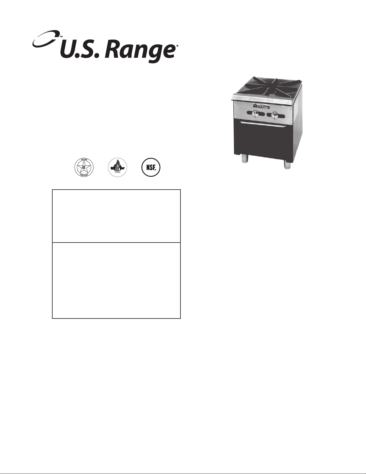
“REGAL” SERIES
STOCK POT STOVES
FOR YOUR SAFETY:
DO NOT STORE OR USE GASOLINE
OR OTHER FLAMMABLE VAPORS OR
LIQUIDS IN THE VICINITY OF
THIS OR ANY OTHER
APPLIANCE
WARNING:
IMPROPER INSTALLATION, ADJUSTMENT,
ALTERATION, SERVICE OR MAINTENANCE
CAN CAUSE PROPERTY DAMAGE, INJURY,
OR DEATH. READ THE INSTALLATION,
OPERATING AND MAINTENANCE
INSTRUCTIONS THOROUGHLY
BEFORE INSTALLING OR
SERVICING THIS EQUIPMENT
AND RETAIN FOR FUTURE REFERENCE.
THIS PRODUCT HAS BEEN CERTIFIED AS
COMMERCIAL COOKING EQUIPMENT AND
MUST BE INSTALLED BY PROFESSIONAL
PERSONNEL AS SPECIFIED.
IN THE COMMONWEALTH OF MASSACHUSETTS
THIS PRODUCT MUST BE INSTALLED BY A
LICENSED PLUMBER OR GAS FITTER. APPROVAL
NUMBER: G-1-07-05-28
For Your Safety:
Post in a prominent location, instructions to be
followed in the event the user smells gas. This
information shall be obtained by consulting
your local gas supplier.
Users are cautioned that maintenance and repairs must be performed by a Garland authorized service agent
using genuine Garland replacement parts. Garland will have no obligation with respect to any product that has been
improperly installed, adjusted, operated or not maintained in accordance with national and local codes or installation
instructions provided with the product, or any product that has its serial number defaced, obliterated or removed,
or which has been modified or repaired using unauthorized parts or by unauthorized service agents.
For a list of authorized service agents, please refer to the Garland web site at http://www.garland-group.com.
The information contained herein, (including design and parts specifications), may be superseded and is subject
to change without notice.
PLEASE READ ALL SECTIONS OF THIS MANUAL
GARLAND COMMERCIAL INDUSTRIES
185 East South Street
Freeland, Pennsylvania 18224
Phone: (570) 636-1000
Fax: (570) 636-3903
Part # 1382699 (02/26/08) © 2005 Garland Commercial Industries, Inc.
Part # 1382699 (02/26/08) Page 1
GARLAND COMMERCIAL RANGES, LTD.
1177 Kamato Road, Mississauga, Ontario L4W 1X4
CANADA
Phone: 905-624-0260
Fax: 905-624-5669
Enodis UK LTD.
Swallow eld Way, Hayes, Middlesex UB3 1DQ ENGLAND
Telephone: 081-561-0433
Fax: 081-848-0041
Page 2

IMPORTANT INFORMATION
WARNING:
This product contains chemicals known to the state of California to cause cancer and/or birth defects
or other reproductive harm. Installation and servicing of this product could expose you to airborne
particles of glass wool/ceramic fibers. Inhalation of airborne particles of glass wool/ceramic fibers
is known to the state of California to cause cancer. Operation of this product could expose you to
carbon monoxide if not adjusted properly. Inhalation of carbon monoxide is known to the state of
California to cause birth defects or other reproductive harm.
Keep appliance area free and clear of combustibles.
Part # 1382699 (02/26/08)Page 2
Page 3

TABLE OF CONTENTS
IMPORTANT INFORMATION. . . . . . . . . . . . . . . . . . . . . . . . . . . . . . . . . . . . . . . . . . 2
INTRODUCTION. . . . . . . . . . . . . . . . . . . . . . . . . . . . . . . . . . . . . . . . . . . . . . . . . . . . . 4
Uncrating . . . . . . . . . . . . . . . . . . . . . . . . . . . . . . . . . . . . . . . . . . . . . . . . . . . . . . . . . . . . . . . . . . . . . . . .4
Rating Plate . . . . . . . . . . . . . . . . . . . . . . . . . . . . . . . . . . . . . . . . . . . . . . . . . . . . . . . . . . . . . . . . . . . . . .4
INSTALLATION . . . . . . . . . . . . . . . . . . . . . . . . . . . . . . . . . . . . . . . . . . . . . . . . . . . . . . 4
Clearances . . . . . . . . . . . . . . . . . . . . . . . . . . . . . . . . . . . . . . . . . . . . . . . . . . . . . . . . . . . . . . . . . . . . . . . 4
Positioning and Setup . . . . . . . . . . . . . . . . . . . . . . . . . . . . . . . . . . . . . . . . . . . . . . . . . . . . . . . . . . . .4
Air Supply and Ventilation . . . . . . . . . . . . . . . . . . . . . . . . . . . . . . . . . . . . . . . . . . . . . . . . . . . . . . . .4
Gas Supply . . . . . . . . . . . . . . . . . . . . . . . . . . . . . . . . . . . . . . . . . . . . . . . . . . . . . . . . . . . . . . . . . . . . . .5
Statutory Regulations . . . . . . . . . . . . . . . . . . . . . . . . . . . . . . . . . . . . . . . . . . . . . . . . . . . . . . . . . . . .5
Manual Shut-O Valve . . . . . . . . . . . . . . . . . . . . . . . . . . . . . . . . . . . . . . . . . . . . . . . . . . . . . . . . . . .5
Pressure Regulator . . . . . . . . . . . . . . . . . . . . . . . . . . . . . . . . . . . . . . . . . . . . . . . . . . . . . . . . . . . . . . .5
Rigid Connections . . . . . . . . . . . . . . . . . . . . . . . . . . . . . . . . . . . . . . . . . . . . . . . . . . . . . . . . . . . . . . .5
Flexible Couplings & Connectors. . . . . . . . . . . . . . . . . . . . . . . . . . . . . . . . . . . . . . . . . . . . . . . . . .6
Manual Pilot Valve . . . . . . . . . . . . . . . . . . . . . . . . . . . . . . . . . . . . . . . . . . . . . . . . . . . . . . . . . . . . . . .6
Testing and Adjustments . . . . . . . . . . . . . . . . . . . . . . . . . . . . . . . . . . . . . . . . . . . . . . . . . . . . . . . . .6
INITIAL OPERATION . . . . . . . . . . . . . . . . . . . . . . . . . . . . . . . . . . . . . . . . . . . . . . . . . 7
Initial Pilot Light . . . . . . . . . . . . . . . . . . . . . . . . . . . . . . . . . . . . . . . . . . . . . . . . . . . . . . . . . . . . . . . . . 7
Final Preparation . . . . . . . . . . . . . . . . . . . . . . . . . . . . . . . . . . . . . . . . . . . . . . . . . . . . . . . . . . . . . . . . .7
CLEANING AND MAINTENANCE . . . . . . . . . . . . . . . . . . . . . . . . . . . . . . . . . . . . . . 7
General Cleaning . . . . . . . . . . . . . . . . . . . . . . . . . . . . . . . . . . . . . . . . . . . . . . . . . . . . . . . . . . . . . . . .7
Daily . . . . . . . . . . . . . . . . . . . . . . . . . . . . . . . . . . . . . . . . . . . . . . . . . . . . . . . . . . . . . . . . . . . . . . . . . . . .7
Periodic . . . . . . . . . . . . . . . . . . . . . . . . . . . . . . . . . . . . . . . . . . . . . . . . . . . . . . . . . . . . . . . . . . . . . . . . .7
Cleaning Stainless Steel . . . . . . . . . . . . . . . . . . . . . . . . . . . . . . . . . . . . . . . . . . . . . . . . . . . . . . . . . .8
SERVICE AND PARTS . . . . . . . . . . . . . . . . . . . . . . . . . . . . . . . . . . . . . . . . . . . . . . . . 8
Part # 1382699 (02/26/08) Page 3
Page 4

INTRODUCTION
U.S. Range manufactures the “Regal” Stock Pot
(SP 1844 & SP-1845) in one size only, roughly 18” square. This
is a single-grate unit, re by a pair of nested ring burners,
which product 45,000 BTU/hr.
All units are shipped completely assembled, with the
pressure regulator and adjustable legs packed on the
drip pan. The burners are tied to their hangers to prevent
vibration damage. All units are inspected at the factory prior
to shipment.
Like any other ne, precision built piece of equipment, it
should be given regular care and maintenance. Periodic
inspections by your dealer or a qualied service agency are
recommended.
Uncrating
After uncrating, immediately check the equipment for visible
signs of shipping damage.
If such damage has occurred, do not refuse shipment, but
contact the shipper and le the appropriate freight claims.
Rating Plate
The rating plate is attached to the inside of stock pot’s body
side and is accessible after removing the burner knobs and
valve cover.
When corresponding with the factory or your local
authorized factory service center regarding service problems
or replacement parts, be sure to refer to the particular unit
by the correct model number (including the prex and sux
letters and numbers) and the warranty serial number. The
rating plate axed to the unit contains this information.
Other information on this plate is the BTU/hr input to the
burners, outlet gas pressure in inches WC, and whether
oriced for natural or propane gas.
WARNING All U.S. Range Stock Pot Stoves must be
connected only to the type of gas identied on the rating
plate! Installation must be in accordance with ANSI 283.11
(latest edition) of the American national Standards Institute,
Inc.
INSTALLATION
Clearances
The appliance area must be kept free and clear of all
combustibles.
These units are design-certied for the following
installations:
1. Intended for other than household use.
2. For use in non combustible locations only.
3. Adjacent to combustible and non-combustible walls with
the following minimum clearances:
Type of Construction
Minimum Clearance
Combustible Non-Combustible
Rear 6” (152mm) Rear 6” (152mm)
Sides 6” (152mm) Sides 6” (152mm)
Positioning and Setup
The stock pot should be placed on a solid, level surface with
ample space to combustible surfaces, as dened under
“CLEARANCES.”
There is no mechanical installation required beyond leveling.
Place a carpenter’s spirit level left-to-right on the landing
ledge and also front-to-back on the center nger of the top
grate. Level to the high corner with the screw adjustment
build into the foot of each leg.
Air Supply and Ventilation
The area around the appliance must be kept clear to avoid
any obstruction to the ow of combustion and ventilation
air, as well as, for ease of maintenance and service.
Part # 1382699 (02/26/08)Page 4
Page 5

INSTALLATION Continued
Means must be provided for any commercial, heavy-duty
cooking appliance to exhaust combustion waste products to
the outside of the building. Usual practice is to place the unit
under an exhaust hood; the minimum should be an exhaust
fan mounted above the unit Filters and drip troughs should
be part of any industrial hood, but consult local codes before
construction and installing a hood.
Strong exhaust fans in this hood or in the overall air
conditioning system can produce a slight vacuum in the
room and/or cause air drafts, either of which can interfere
with pilot or burner performance and be hard to diagnose.
Air movement should be checked during installation; if
pilot/burner outage problems persist, make-up air openings
or baes may have to be provided in the room.
Gas Supply
1. Installation of the equipment should be made by a
licensed plumber.
2. A gas shut-o valve must be installed in the gas supply
line ahead or the appliance for safety and for ease of
future service.
3. A gas pressure regulator must be installed at the
appliance prior to connecting the equipment to the gas
line. Failure to install a regulator will void the equipment
warranty.
Manual Shut-O Valve
This installer-supplied valve must be installed in the gas
service line ahead of the appliance and regulator in the gas
stream and in a position where it can be reached quickly in
the event of an emergency.
Pressure Regulator
All heavy-duty, commercial cooking equipment must have
a pressure regulator in the incoming service line for safe and
ecient operation, since service pressure may uctuate with
local demand. The manual shut-o valve is normally supplied
by the installer, but pressure regulators are shipped from U.S.
Range with every stock pot.
Regulators are pre-set at the factory for 5” WC (natural gas)
or 10” WC (propane) according to the customer’s ordering
instructions.
Prior to connecting the regulator, check the incoming line
pressure, as these regulators can withstand a maximum
pressure of 1/2 psi (14” WC). If the Line pressure is beyond
this limit, a step-down regulator will be required. Doublecheck the arrow forged onto the bottom of the regulator
body which shows gas ow directions; it should point
downstream to the appliance. The red air-vent cap is part of
the regulator and should not be removed unless local codes
require external venting.
NOTE: The gas supply (service) line must be the same size or
greater than the inlet line of the appliance. U.S. Range Stock
Pots use a 3/4” NPT inlet. Sealant on all pipe joints must be
resistive to LP gas.
Statutory Regulations
Safe and satisfactory operation of your equipment depends,
to a great extent, on its proper installation. Installation must
conform to local codes or, in the absence of local codes with
the National Fuel code, ANSI Z223.1, Natural Gas Installation
Code, CAN/CGA-B149.1, or the Propane Installation Code,
CAN/CGA-B149.2, as applicable, including:
1. The appliance and its individual shuto valve must be
disconnected from the gas supply piping system during
any pressure testing of that system at test pressures in
excess of 1/2 psi (3.45 kPa).
2. The appliance must be isolated from the gas supply
piping system by closing its individual manual shuto
valve during any pressure testing of the gas supply
piping system at test pressures equal to or less than 1/2
psi (3.45 kPa)
Regulators can be adjusted in the eld, but it is
recommended that they not be tampered with unless that
part is known to be out of adjustment or serious pressure
uctuations are found to exist and can be solved no other
way. Any adjustments to regulators must be made by
qualied service personnel with proper test equipment.
WARNING Failure to install a pressure regulator will void
the equipment warranty!
Rigid Connections
Double-check any installer-supplied intake pipes visually
and clear any dirt particles, threading chips, or other foreign
matter before installing in a service line. Those particles will
clog orices when gas pressure is applied.
WARNING All connections must be sealed with a joint
compound suitable for LP gas, and all connections must be
tested with a soapy solution before lighting any pilots!
Part # 1382699 (02/26/08) Page 5
Page 6

INSTALLATION Continued
Flexible Couplings & Connectors.
If the unit is to be installed with exible couplings and/or
quick-disconnect ttings, for an appliance equipped with
casters, the installation shall be made with a connector that
complies withthe Standard for Connectors for Movable Gas
Appliances, ANSI Z21.69 /CSA 6.16, and a quick-disconnect
device that complies with the Standard for Quick-Disconnect
Devices for Use With Gas Fuel, ANSI Z21.41 / CSA 6.9, and
adequate means must be provided to limit the movement
of the appliance without depending on the connector and
the quick-disconnect device or its associated piping to limit
the appliance movement and the location(s) where the
restraining means may be attached to the appliance shall be
specied.
Further, if the unit is to be installed on a non-combustible
surface that is equipped with casters, means must be
provided to limit the movement of the unit on this surface.
Manual Pilot Valve
Both burners of the ring burner pair are lighted from one
constant-burning pilot. These should be manually lighted
immediately after the gas is turned on and the system is
checked for leaks. An adjustment screw for each pilot is
located on the gas manifold and can be accessed through
openings in the valve panel between the valve knobs.
Testing and Adjustments
Check all gas connections for leaks using a soapy solution
before lighting any pilots. DO NOT USE OPEN FLAME
TO CHECK FOR LEAKS! Putting open ame beside a new
connection is not only dangerous, but will often miss small
leaks that a soapy solution would nd.
All U.S. Range appliances are adjusted and tested before
leaving the factory, eectively matching them to sea
level conditions. Adjustments and calibrations to assure
proper operation may be necessary on installation to meet
local conditions, low gas pressure, dierences in altitude;
variations in gas characteristics, to correct possible problems
caused by rough handling or vibration during shipment, and
are to be performed only by qualied service personnel.
These adjustments are the responsibility of the customer,
installer and/or dealer and are not covered by the U.S. Range
warranty.
Part # 1382699 (02/26/08)Page 6
Page 7

INITIAL OPERATION
Initial Pilot Light
Initial pilot light is in the following sequence:
1. Turn the manual shut-o valve on the incoming service
line “OFF”.
2. Turn all burner valves “OFF”.
3. Close all pilot adjusting screws (clockwise turn all the
way in).
4. Wait for any accumulated gas to disperse.
5. Open the manual shut-o valve.
6. Apply a lighted match or taper to a pilot burner and open
that pilot’s adjustment screw gradually until the pilot
lights.
7. Adjust the pilot ame for the desired characteristics.
8. Turn “ON” that main burner and watch to make sure it
lights from the pilot, then turn the burner “OFF”.
9. Repeat steps 6 through 8 to light all remaining pilots.
If only one pilot has gone out, it is not necessary to follow
the entire procedure outlined above. Merely apply a lighted
match or taper to the pilot until it lights, then adjust the pilot
valve. If the pilot will not light, close the adjustment valve
completely, do not use that burner, and call for service.
NOTE: It may be necessary to re-light the pilots several
times until the new lines are purged of any trapped air and
constant gas ow is attained.
Final Preparation
New units are wiped clean with solvent at the factory to
remove any visible signs of dirt, oil, grease, etc., remaining
from the manufacturing process. They should be washed
with hot, soapy water to remove any solvent or oil residue or
installation dust or debris before using for food preparation.
CLEANING AND MAINTENANCE
WARNING If gas odors are detected, the gas supply must
be turned “OFF’ at the main shut-o valve and the local
gas company or authorized service agency contacted for
service.
General Cleaning
Any piece of equipment works better and lasts longer when
maintained properly and kept clean. Cooking equipment is
no exception. Your U.S. Range stock pot must be kept clean
during the working day and thoroughly cleaned at the end
of each day.
Daily
Check the drip pan frequently. Wipe up spills as they occur,
and drain the pan as necessary during the day.
At the end of each day, remove the burners and wash in hot,
soapy water, then re-assemble. Remove the outer burner rst
by lifting slightly to clear the inner burner, sliding to the rear
to clear the burner valve orice, then lifting out. Remove the
inner burner in the same matter.
Remove the drip pan and wash thoroughly.
Clean the counter surface under and around the Stock pot
Periodic
Your U.S. Range stock pot should be checked and adjusted
periodically by qualied service personnel as part of a regular
kitchen maintenance program.
Part # 1382699 (02/26/08) Page 7
Page 8

CLEANING AND MAINTENANCE Continued
Cleaning Stainless Steel
All stainless steel body parts should be wiped regularly with
hot, soapy water during the day, and with a liquid cleaner
designed for this material at the end of each day. Do not
use steel wool, abrasive cloths, cleansers, or powders! If it
is necessary to scrape stainless steel to remove encrusted
materials, soak the encrusted area with wet cloths to loosen
the material, then use a wood or nylon scraper. Do not use
a metal knife, spatula, or any other metal tools to scrape
stainless steel. Scratches are almost impossible to remove.
SERVICE AND PARTS
Installation, maintenance and repairs should be performed
by your local authorized U.S. Range service agency listed in
your information manual pamphlet.
Part # 1382699 (02/26/08)Page 8
Page 9

Part # 1382699 (02/26/08) Page 9
Page 10

Part # 1382699 (02/26/08)Page 10
Page 11

Part # 1382699 (02/26/08) Page 11
Page 12

 Loading...