

Page 1
U.S. Range/ALCO
A Division of ALCO Foodservice Equipment Company
INSTALLATION INSTRUCTIONS
"CUISINE77 Deep Fat Fryers
Models 836/841-1414-1 & -2
All U.S. Range equipment is manufactured for use with the type of gas specified on
the rating plate and for installation in accordance with ANSI Z-223.1 (latest edition) of
the National Fuel Gas Code. Copies may be obtained from the American Gas
Association, 1515 Wilson Blvd., Arlington, VA - 22209.
FOR YOUR SAFETY
Do not store or use gasoline or other flammable
vapors and liquids in the vicinity of this or any
other appliance.
Instructions to be followed in case the user smells gas are to be posted in a prominent location. This information shall be obtained by contacting the local gas company or gas supplier.
PLEASE RETAIN THIS MANUAL FOR FUTURE REFERENCE.
Page 2
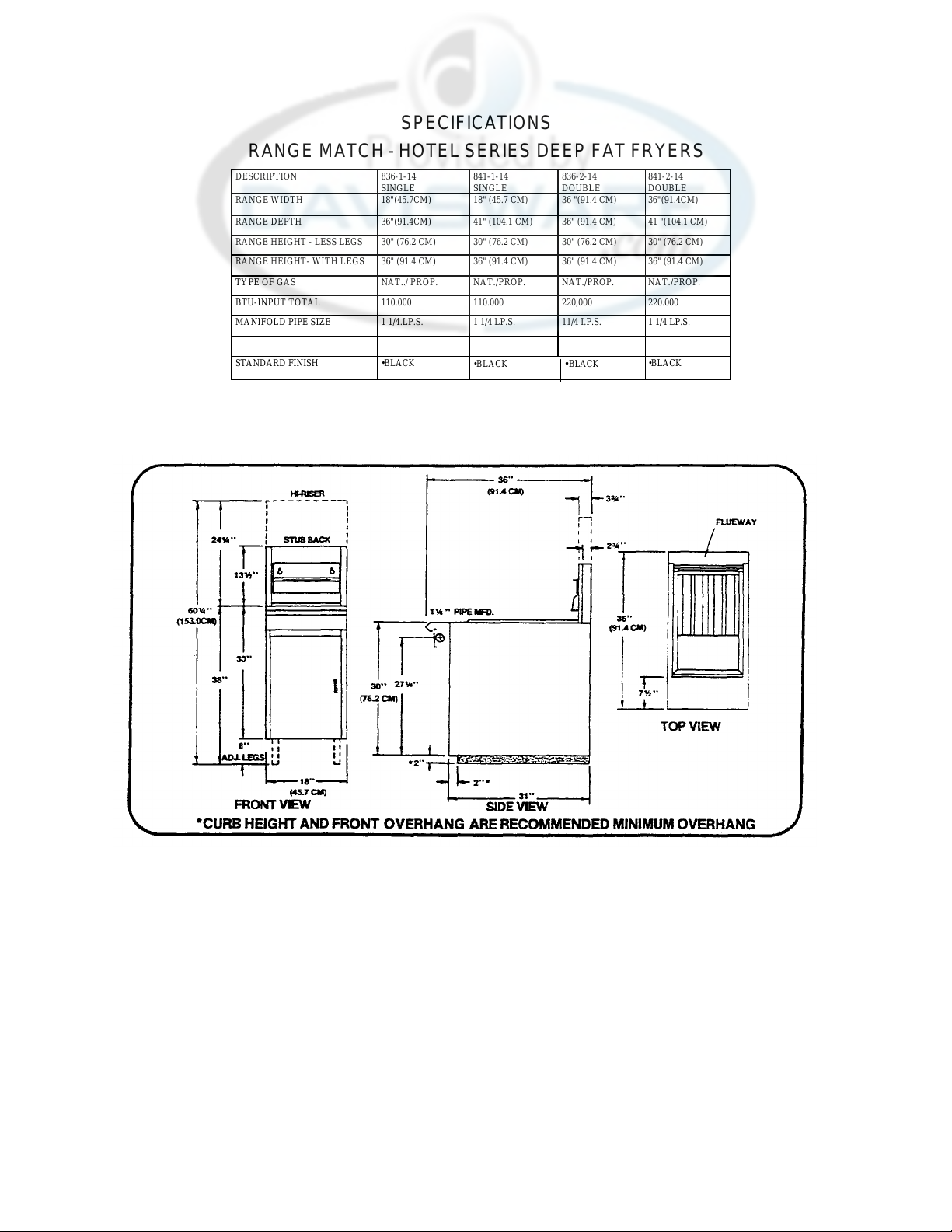
SPECIFICATIONS
SINGLE
SINGLE
DOUBLE
DOUBLE
RANGE MATCH - HOTEL SERIES DEEP FAT FRYERS
DESCRIPTION 836-1-14
RANGE WIDTH 18"(45.7CM) 18" (45.7 CM) 36 "(91.4 CM) 36"(91.4CM)
RANGE DEPTH 36"(91.4CM) 41" (104.1 CM) 36" (91.4 CM) 41 "(104.1 CM)
RANGE HEIGHT - LESS LEGS 30" (76.2 CM) 30" (76.2 CM) 30" (76.2 CM) 30" (76.2 CM)
RANGE HEIGHT- WITH LEGS 36" (91.4 CM) 36" (91.4 CM) 36" (91.4 CM) 36" (91.4 CM)
TYPE OF GAS NAT../ PROP. NAT./PROP. NAT./PROP. NAT./PROP.
BTU-INPUT TOTAL 110.000 110.000 220,000 220.000
MANIFOLD PIPE SIZE 1 1/4.LP.S. 1 1/4 LP.S. 11/4 I.P.S. 1 1/4 LP.S.
STANDARD FINISH •BLACK
•SILVERCO FINISH OPTIONAL AT NO EXTRA COST. STAINLESS STEEL AVAILABLE AT NOMINAL ADDITIONAL COST.
841-1-14
•BLACK •BLACK
836-2-14
841-2-14
•BLACK
Page 3

IMPORTANT
Safe and satisfactory operation of your equipment
depends to a great extent on its proper installation.
Installation must conform to local codes or, in the absence
of local codes, with the National Fuel Code, ANSI Z-223.1-
1980 (or latest edition).
U.S. Range manufactures the "Cuisine" Deep Fat Fryer in either a single or double tank model, either of
which can be 36" or 41" deep overall. Internal parts are all interchangeable and there are no differences in
installation between models.
All "Cuisine" Deep Fat Fryers are shipped completely assembled, with the legs or optional casters
packed inside the fryer tank. All units are adjusted, tested, and inspected at the factory prior to crating for
shipment.
After uncrating, immediately check the equipment for visible signs of
shipping damage. If such damage has occurred, do not refuse shipment, but
contact the shipper and file the appropriate freight claims.
General
1. Installation of the equipment should be made by a licensed plumber.
2. A manual gas shut-off valve must be installed in the gas supply line ahead of
the appliance in the gas stream for safety and for ease of future service.
Rating Plate
This is riveted to the inside of the fryer-door.
Information on this plate includes the model and serial numbers ... when
communicating with the factory about a unit or requesting special parts or
Form CU-DFF 08/84
Page 4

information, this data is essential for proper identification. Other information on this plate is the BTU/hr
output of the burners, outlet gas pressure in inches WC, and whether orificed for natural or propane
gas.
"CUISINE" DEEP FAT FRYERS MUST BE CONNECTED
ONLY TO THE TYPE OF GAS IDENTIFIED ON THE RATING PLATE!
Clearances
The appliance area must be kept free and clear of all combustibles. This unit is design-certified
for the following installations:
1. For locations having non-combustible walls;
2. For installation on a combustible floor when equipped with six inch legs or casters;
3. For installation without legs on a non-combustible curb or platform; and
4. For battery installation with other "Cuisine" appliances.
Mechanical
Legs or optional casters should be installed near where the appliance is to be used, as neither
are secure for long transit. After uncrating, tilt the body only high enough (or raise it about a foot) to
permit the legs or casters to be screwed into their couplings, and lower it gently to keep any undue
strain from the legs. It is strongly recommended that a pallet or lift jack be used rather than tilting.
A carpenter's spirit level should be placed across the top of the fryer and the unit levelled both
front-to-back and side-to-side. If it is not level, burner combustion may be erratic, the unit will not
function efficiently, and (in a line-up) it will not match the line visually.
If the floor is smooth and level, level the unit with the screw thread of the legs or casters; adjust
to the high corner and measure with the spirit level. If the floor is uneven or has a decided slope, level
the unit with metal shims; the adjustment required may exceed the thread available in the leg or caster
and/or a castered unit will probably not return to exactly the same position after being moved,
requiring relevelling after each move.
Form CU-DFF 08/84
Page 5
Do not push against any edges of the unit in an attempt to adjust its
position! Although all metal parts are deburred during manufacture, accidents
could occur if the fryer should move suddenly while being pushed into position by
hand. Pushing a unit into position (rather than using a lift jack) also increases
the probability of bending the leg or caster spindles or the internal coupling
connectors.
Battery Assembly
The "Cuisine" standard 36" width and front manifold open on both ends were
designed to facilitate joining the units into a cooking line. This unit can be
added to an already existing line or be part of a new line-up. Once inserted into
its proper position and levelled, installation is the same as if it were standing
alone.
NOTE: The "Cuisine" Deep Fat Fryer does not have a removable front landing ledge!
That piece is part of the one-piece top. Installation will require an
off-set wrench to to able to tighten the union collar which connects to a
neighboring manifold.
NOTE: Local building codes will usually not permit a Deep Fat Fryer (with its
open tank of hot grease) to be mounted immediately next to an open flame
of any type, whether a broiler or the open burner of a range. Check the
local codes before beginning installation.
Adding a unit to a cooking line is in the following sequence:
1. Place all units to be batteried in their approximate locations in the line, or
open an existing line at the appropriate position and insert the fryer.
2. Remove the valve covers of adjacent units.
3. Level the fryer to match the units on either side at the front manifold.
4. Connect these units loosely at the front manifold ends.
5. Level the rear of the fryer to match adjacent units.
6. Secure the front manifold.
7. Plumb the feed lines as necessary. Cap the open end of the manifold if
exposed. The half-union supplied on the end of the manifold must be removed in
order to cap that end.
8. Replace all valve covers, landing ledges, and knobs.
Form CU-DFF 08/84
Page 6

Air Supply & Ventilation
5
The area around the appliance must be kept clear to avoid any obstruc tion to the flow of
combustion and ventilation air as well as for ease of maintenance and service. Under no conditions is
the interior of the fryer's cabinet to be used for storage!
Means must be provided for any commercial, heavy-duty cooking appliance to exhaust
combustion waste products to the outside of the building. It is essential that a Deep Fat Fryer be set
under a powered exhaust hood or that an exhaust fan be provided in the wall above the unit, as
exhaust gas temperatures are in the vicinity of 1400 degrees. These temperatures, in addition to the
open tank of hot oil, make the storage of anything on shelving behind or over the fryer unsafe. Filters
and drip troughs should be part of any industrial hood, but consult local codes before constructing
and installing a hood.
Strong exhaust fans in this hood or in the overall air conditioning system can produce a slight
vacuum in the room and/or cause air drafts, either of which can interfere with pilot or burner
performance and be hard to diagnose. Air movement should be checked during installation; if
pilot/burner outage problems persist, make-up air openings or baffles nay have to be provided in the
room.
Gas Connection
NOTE: The gas supply (service) line must be the same size or greater than the inlet line of the
appliance. "Cuisine" Deep Fat Fryers use a 1-1/4" NPT (Sch40) inlet. Sealant on all
pipe joints must be resistive to LP gas.
Manual Shut -off Valve
This installer-supplied valve must be installed in the gas service line ahead of the appliance and
regulator in the gas stream and in a position where it can be reached quickly in the event of an
emergency.
Pressure Regulator
All heavy-duty, conmercial cooking equipment must nave a pressure regulator on the incoming
service line for safe and efficient operation, since
Form CU-DFF 08/84
Page 7
service pressure may fluctuate with local demand. External regulators are not required on the "Cuisine" fryer,
as that function is performed by a safety control valve.
The "Cuisine" Deep Fat Fryer can be installed to either natural or propane gas, dependi ng on the
customer's ordering specifications. The correct safety control valve and orifices are installed at the factory for
the appropriate gas, and while the valve can be adjusted in the field, any adjustment should be made only by
qualified service personnel with the proper test eauipment.
Line pressure should be checked with a manometer; natural gas requires 5" WC and propane requires 10".
Rigid Connections
The fryer can be connected singly or as part of a cooking line. The connection into a cooking line was
outlined above. The stand-alone fryer (single or double tank) can be connected with an installer -supplied intake
pipe from the shut-off valve on the intake line to either side of the manifold pipe (cap the other end). Check any
installer-supplied intake pipe visually and/or blow them out with compressed air to clear dirt particles, threading
chips, or any other foreign matter before installing into a service line. Those particles will clog orifices when gas
pressure is applied.
All connections must be sealed with a joint compound suitable for LP gas, and all
connections must be tested with a soapy solution before lighting any pilots!
Flexible Couplings, Connectors, Casters
If the unit is to be installed with flexible couplings and/or quick -disconnect fittings, the installer must use
a heavy-duty, AGA design-certified commercial flexible connector of at least 1-1/4" NFT (with suitable strain
reliefs) in compliance with ANSI Z-21.69-1979. Domestic connectors are not suitable!
If the unit is to be installed with casters, the same ANSI Standard applies and, in addition, some means
must be found to limit the movement of the unit without relying on its associated piping or fittings.
Form CU-DFF 08/84
Page 8
Initial Pilot Light
All U.S. Range appliances are adjusted and tested before leaving the factory, effectively
matching them to sea level conditions. Adjustments and calibrations to assure proper operation may
be necessary on installation to meet local conditions, low gas pressure, differences in altitude,
variations in gas characteristics, to correct possible problems caused by rough handling or vibration
during shipment, and are to be performed only by qualified service personnel. These are the
responsibility of the customer and/or dealer and are not covered by U.S. Range warranty.
Check all gas connections for leaks using a soapy solution before lighting any pilots. DO NOT
USE AN OPEN FLAME TO CHECK FOR LEAKS! Putting an open flame beside a new connection is
not only dangerous, but will often miss small leaks that a soapy solution would find.
Incoming gas is brought from the upper manifold pipe through a manual shut -off valve to the pilot
safety valve, located at the lower right rear within the fryer cabinet. Gas travels from this safety valve
to the pilot burner, which is located up high in the center, between the two widely-spaced center
burners and against the fryer tank.
Pilot light or relight is in the following sequence:
1. Turn off the manual shut -off valve on the incoming service line.
2. Turn off the manual shut -off valve on the manifold.
3. Turn the thermostat "off".
4. Depress the grey pilot gas cock dial on the safety control valve and turn "off".
5. Wait for any accumulated gas to disperse.
6. Fill the fryer tank with oil (or at least water during testing) to above the heat transfer tubes.
WARNING !
If the main burners are operated with the tank empty, the heat transfer tubes may
easily burn through. They are not replacement parts without replacing the entire tank!
Form CU-DFF 08/84
Page 9
7. Open the manual shut -off valve on the incoming service line.
8
8. Open the manual shut -off valve at the manifold.
9. Apply a lighted match or taper to the pilot burner head.
10. Turn the gas cock dial on the safety valve to "pilot", depres s and hold the dial until the pilot
remains lighted when the dial is released.
11. If the pilot does not stay lit, depress the dial and relight the pilot, holding the dial in longer than
thirty seconds before releasing.
12. When the pilot stays lit, turn the gas cock dial to "on".
13. Turn the thermostat to any "on" setting and watch to make sure the main oven burners ignite
from the pilot.
NOTE: It may be necessary to relight the pilot several times until the lines are purged of any trapped
air and a constant gas flow is attained.
WARNING!
When lighting pilots and checking for burner operation, do not stand with
your face close to the burners. They will light with a "pop" and could flash back
and cause facial burns.
Final Preparation
Mew units are wiped clean with solvents at the factory to remove any visible signs of dirt, oil,
grease, etcetera remaining from the manufac turing process, then coated with a thin film of mineral oil.
They "should be washed thoroughly with hot, soapy water to remove these film residues and any
installation dust or debris before being used for food preparation, then rinsed out and wiped dry.
Close the drain valve completely and remove the crumb screen, Make sure the screws holding the
thermostat and limit control sensing bulbs into the tank are tight.
When using a liquid shortening (cooking oil), fill the fryer at least to the "oil level" line scribed into
the back of the tank.
When using solid shortening, either melt it first or cut it into small pieces and pack it below the
heat tubes, between the tubes, and on top of the tubes, leaving no air spaces around the tubes and
being careful not to disturb the sensing bulbs. Melt this shortening by turning the burners on
Form CU-DFF 08/84
Page 10
for about five seconds, off for fifteen seconds, on for five, off for fifteen, etcetera, until the shortening
is melted. If you see any smoke coming from the oil while melting this way, shorten the "on" cycle and
lengthen the "off" cycle (to melt more slowly), as smoke shows that you are scorching the shortening
and cutting its useful life.
Never attempt to melt a solid block of shortening by setting it on top of
the heat tubes. This is unsafe, dangerous, and will void the fryer
warranty.
When the fryer tank is filled and the shortening melted, replace the crumb screen over the heat
tubes.
Before starting operation, turn the thermostat to the probable working temperature (usually 350
degrees), wait for the temperature to stabilize, and check the thermostat by using a high-quality
immersion thermometer.
WARNINGS!
+ Do not move a fryer when filled with a hot liquid.
+ Do not go near the area directly over the flue outlet when the fryer is working.
+ Always wear oil-proof, insulated gloves when working with the fryer filled with hot oil.
+ Always drain hot oil into a metal container . . .hot oil can melt plastic buckets.
Cleaning & Maintenance
Any piece of equipment works better and lasts longer when maintained properly and kept clean.
Cooking equipment is no exception. Your "Cuisine" Deep Fat Fryer must be kept clean during the
working day and thoroughly cleaned at the end of each day.
Daily
1. Remove and wash all removable parts.
2. Clean ail exterior surfaces of the body. Do- not use cleansers,
Form CU-DFF 08/84
Page 11
steel wool or any other abrasive material on stainless steel.
10
3. Filter the cooking oil and replace if necessary. The oil should be
filtered more often than daily under heavy use conditions.
Weekly
1. Completely drain the fryer tank into a steel container. Do not use a plastic
bucket! If the frying compound is liquid enough to pour through a drain
spout, it is also probably hot enough to melt plastic.
2. Clean the vessel with a good grade of cleaner or hot water and a strong
detergent.
3. Close the drain valve and refill with either cleaner or detergent/water .
4. Bring to a rolling boil, turn the heat down, and let the mixture stand until
deposits and/or carbon spots can be rubbed off.
5. Scrub the tank walls and heat tubes, then drain and rinse with clear water.
6. Refill with clear water and boil again.
7. Drain, rinse, then dry thoroughly.
8. Refill with cooking oil or frying compound as directed above.
Periodic
Your "Cuisine" Deep Fat Fryer should be checked and adjusted
periodically by qualified service personnel as part of a regular kitchen
maintenance program.
Stainless Steel
All stainless steel body parts should be wiped regularly with hot, soapy water
during the day and with a liquid cleaner designed for this material at the end of
each day. Do not use steel wool, abrasive cloths, cleansers, or powders' If it is
necessary to scrape stainless steel to remove encrusted materials, soak with hot,
wet cloths to loosen the material, then use a wood or nylon scraper. Do not use a
metal knife, spatula, or any other metal tool to scrape stainless steel! Scratches
are almost impossible to remove.
Form CU-DFF 08/84
Page 12
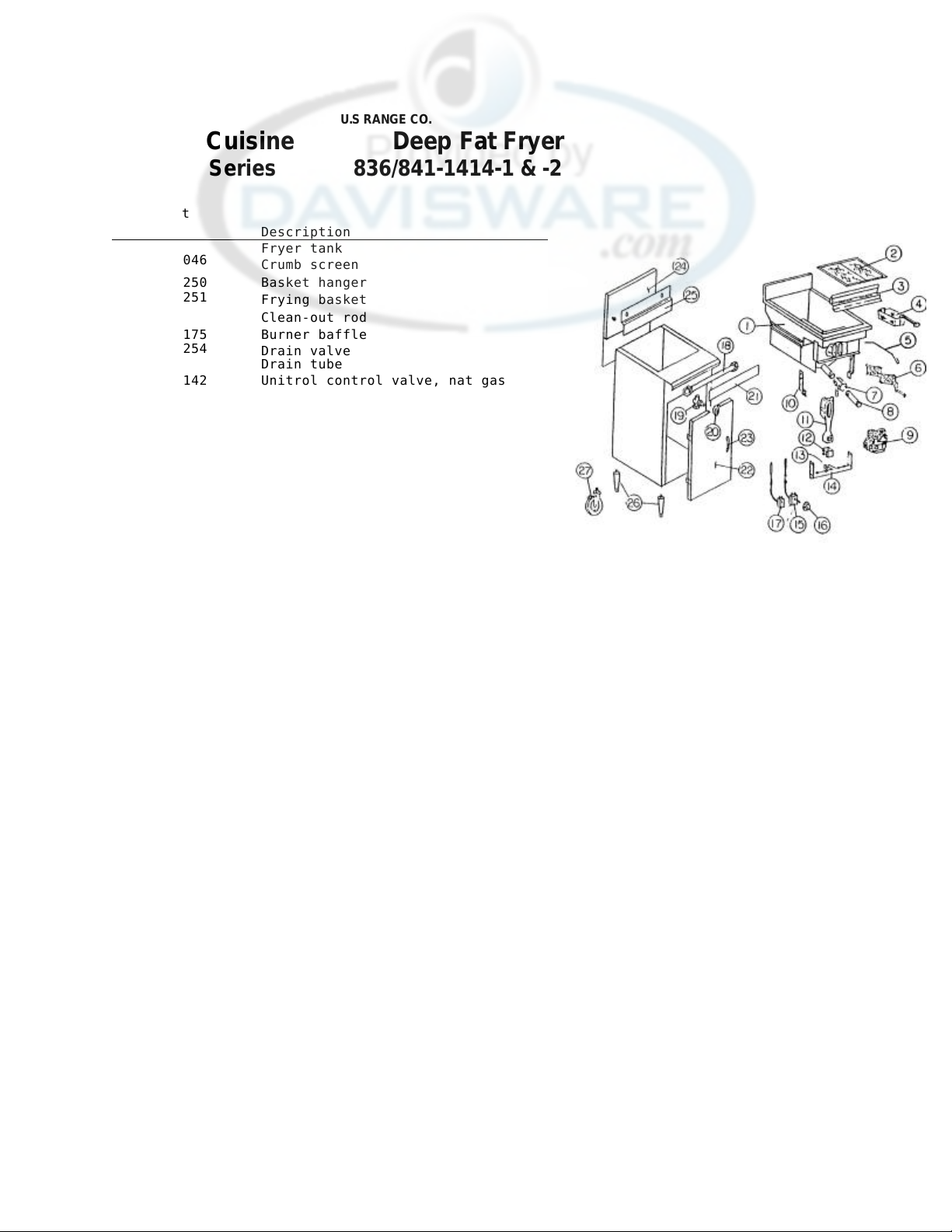
Item Part
No No
Description
7
Drain valve
Drain tube
11
222120
Main burner
12
223250
Air shutter
Optional casters, locking brake Optional
U.S RANGE CO.
Cuisine Deep Fat Fryer
Series 836/841-1414-1 & -2
1 2
226046
3 4 228250
228251
5
6
224175
223254
9
227142
227146
227125
10
223253
13
223248
223249
223252
14
15
227141
16
17
227143
18
251686-1
251686-2
19
227032
20
224002
21
251623-3
251623-5
22
251620-1L
251620-3L
251620-3R
23
224020
24
251504-1
251504-2
25
228080
26 223231
223234-1
223234-2
Fryer tank
Crumb screen
Basket hanger
Frying basket
Clean-out rod
Burner baffle
Unitrol control valve, nat gas
Unitrol control valve, propane
Unitrol conversion kit, N/G to L/P
Manifold support bracket
Orifice, nat gas
Orifice, propane
Manifold
Thermostat, complete
Thermostat, knob only
High limit thermostat
Upper manifold pipe, 18"
Upper manifold pipe, 36"
Gas manual shut-off valve
Gas manual shut-off valve, knob only
Valve cover, 18"
Valve cover, 36"
Door, single tank, L/H
Door, double tank, R/H
Door, double tank, R/H
Door, handle only
Stub back ass'y. single tank
Stub back ass'y, double tank
Backet hanger
Adjustable legs, each
casters, non-locking
Page 13
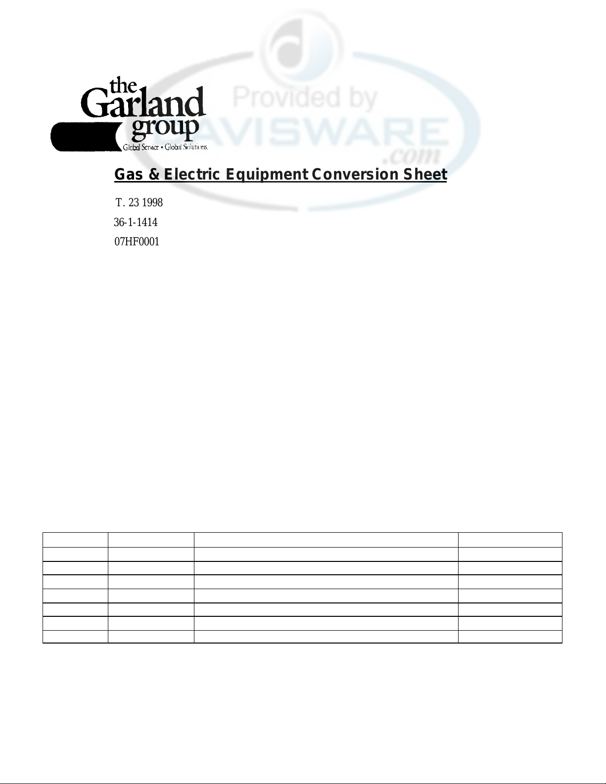
1 228052
-
9 REGULATOR NAT
1 1/4"
3 223249
-
44 BURNER ORIFICE NATURAL GAS
1 227144
PILOT ORIFICE NATURAL GAS
1 227142
COMBINATION VLV NAT
Gas & Electric Equipment Conversion Sheet
DATE: SEPT. 23 1998
MODEL #: 836-1-1414
SERIAL #: 9807HF0001
TYPE OF GAS BEING USED PRESENTLY: PROPANE
EXISTING MANIFOLD PRESSURE: 10 "WC
ELECTRICAL RATING: N/A AMPS
N/A VOLTS
N/A PHASE
ELEVATION: UNDER 2000'
CONVERSION REQUIRED: PROPANE -- NATURAL
NEW MANIFOLD PRESSURE: 5.0 "WC
COMPANY: GCS SERVICE
REQUESTED BY: RANDY
TELEPHONE #: FAX#: 650B 871 4019
It is recommended that a Garland Authorized Service Centre perform conversions.
Parts and special instructions necessary to complete the conversion are listed below:
Quantity Part Number Part Description List Price ($) ea.
Special Instructions:
Please Note: When converting a unit from one type of gas to another, the representative from the authority having
jurisdiction may request the rating plate be changed. If you any questions and/or concerns please call
The Garland Group Service Department at 1-800-427-6668
Page 14
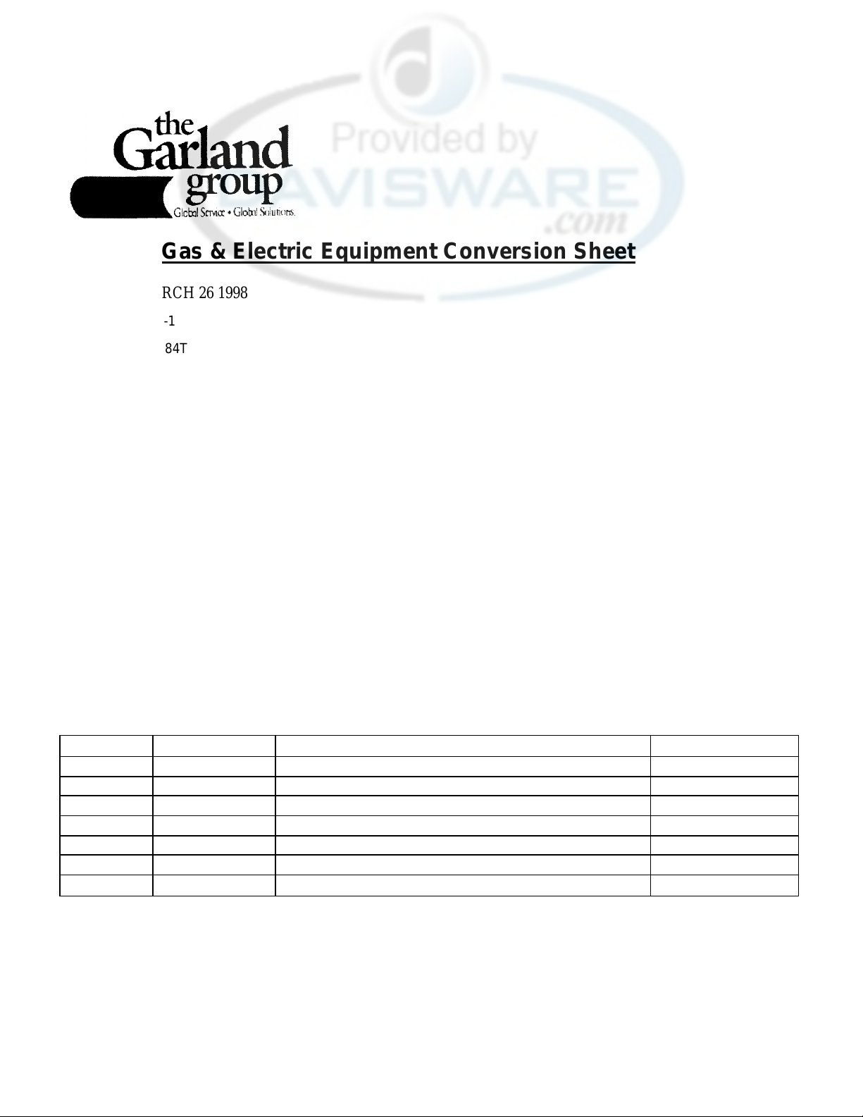
1 228052
-
9 REGULATOR NAT
1 1/4"
3 223242
-
50 GRIDDLE BURNER ORFICE
Gas & Electric Equipment Conversion Sheet
DATE: MARCH 26 1998
MODEL #: 0836-1
SERIAL #: 042584T
TYPE OF GAS BEING USED PRESENTLY: PROPANE
EXISTING MANIFOLD PRESSURE: 10 "WC
ELECTRICAL RATING: N/A AMPS
N/A VOLTS
N/A PHASE
ELEVATION: UNDER 2000' CONVERSION REQUIRED: PROPANE -- NATURAL
NEW MANIFOLD PRESSURE: 5.0 "WC
COMPANY: ELMER SHULTZ SERVICES
REQUESTED BY: PETE
TELEPHONED FAX#: 609 641 8703
It is recommended that a Garland Authorized Service Centre perform conversions.
Parts and special instructions necessary to complete the conversion are listed below:
Quantity Part Number Part Description List Price ($) ea.
Special Instructions:
Please Note: When converting a unit from one type of gas to another, the representative from the authority having jurisdiction
may request the rating plate be changed. If you any questions and/or concerns please call The Garland
Group Service Department at 1-800-427-6668
Page 15
Page 16
Page 17
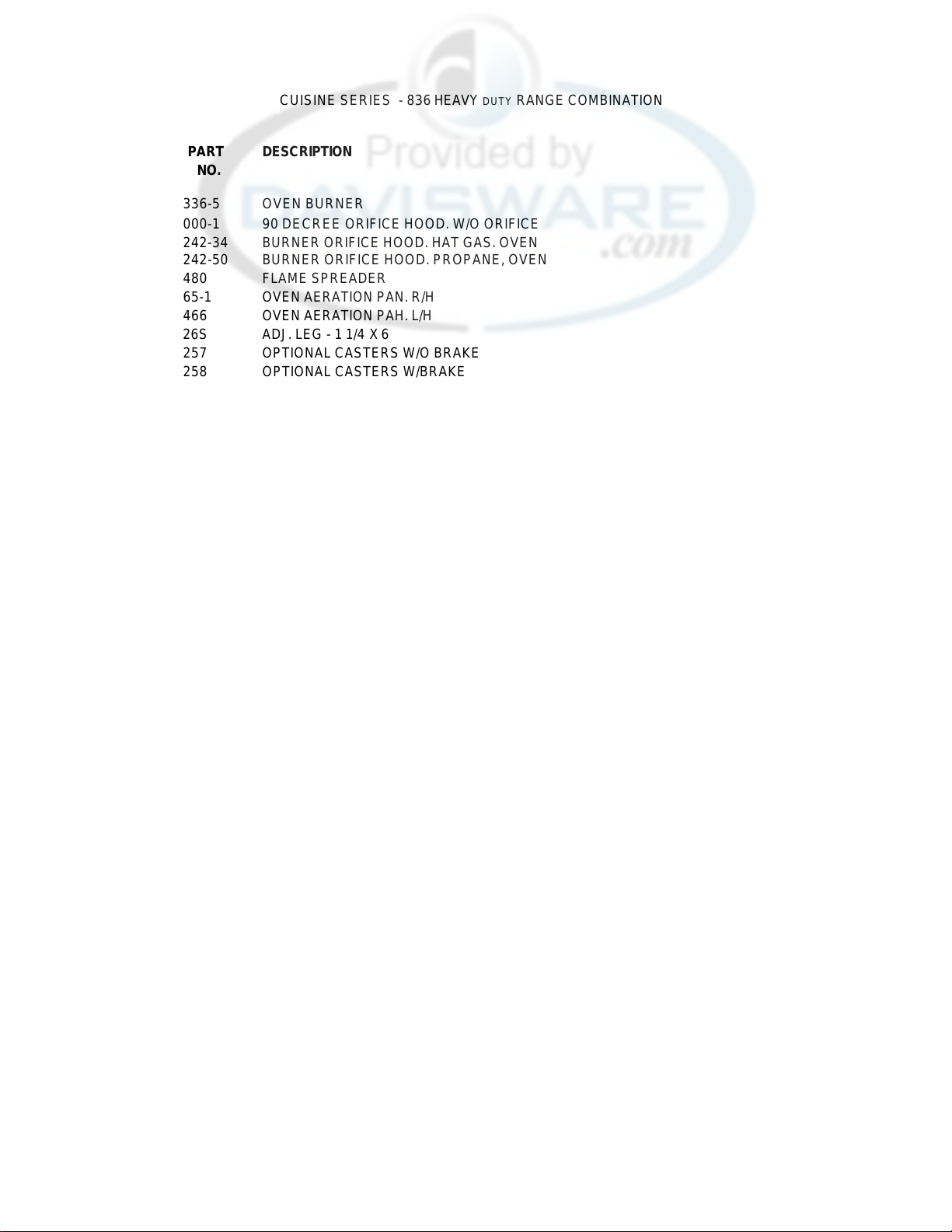
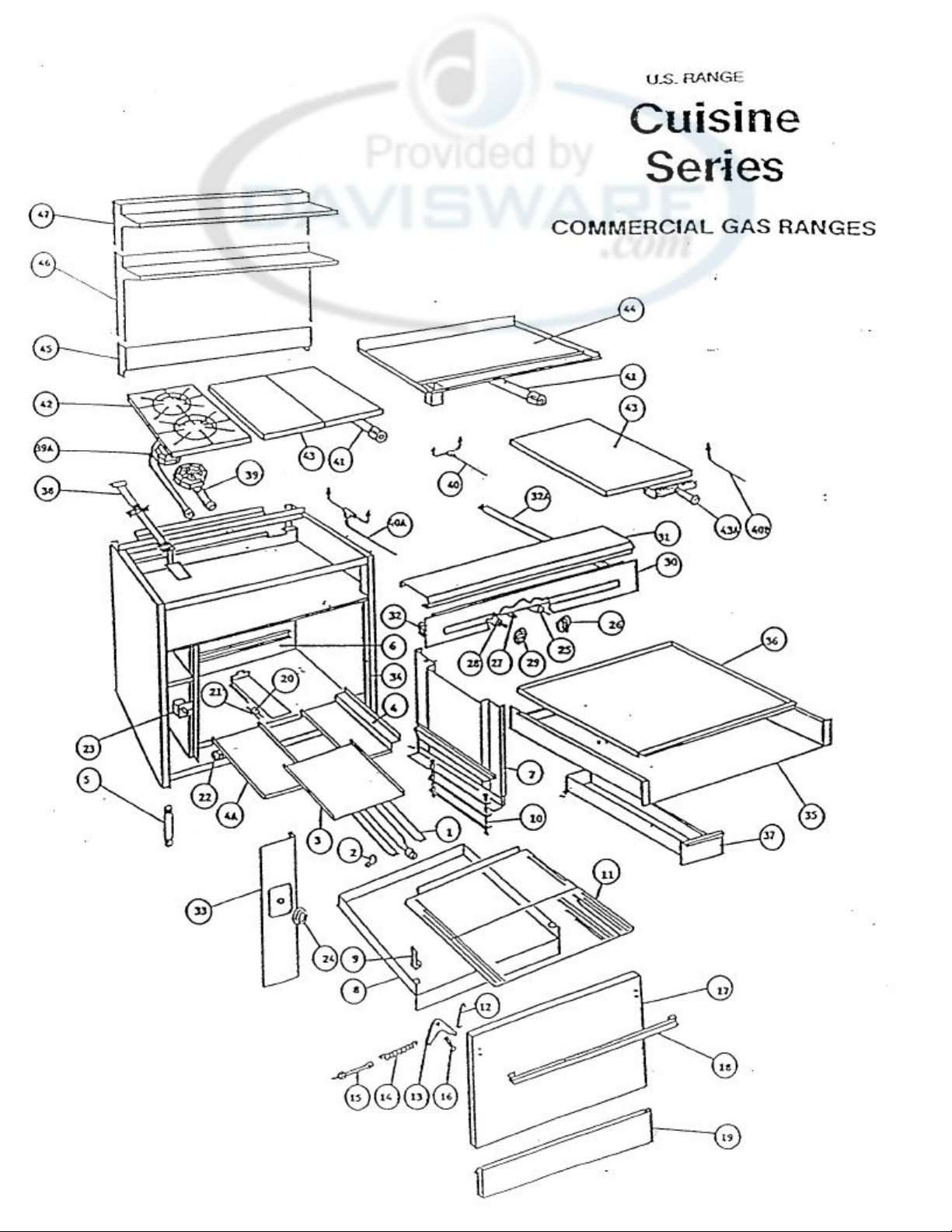
CUISINE SERIES - 836 HEAVY DUTY RANGE COMBINATION
15 225003
OVEN DOOR EYE BOLT
ITEM
NO.
1 252336-5 OVEN BURNER
2 223000-1 90 DECREE ORIFICE HOOD. W/O ORIFICE
223242-34 BURNER ORIFICE HOOD. HAT GAS. OVEN
3 261480 FLAME SPREADER
4 25165-1 OVEN AERATION PAN. R/H
4A 251466 OVEN AERATION PAH. L/H
5 22326S ADJ. LEG - 1 1/4 X 6
6 251473 OVEN INSIDE BACK LINER. PORC
7 251471-1 OVEN INSIDE R/H SIDE LINER. PROC
8 251479 OVEN INSIDE BOTTOM PAN. PORC
9 252097 BOTTOM PAH HOLD-DOWN TAB
10 226016-1 OVEN RACK SUPPORT. R/H
226016-2 OVEN RACK SUPPORT US
11 226017 OVEN RACK - 26 3/4 X 24 5/8
12 224009 OVEN DOOR LINKAGE
13 224012 OVEN DOOR ROCKER ARM
14 224004 OVEN DOOR CLOSURE SPRING
PART
NO.
223242-50 BURNER ORIFICE HOOD. PROPANE, OVEN
223257 OPTIONAL CASTERS W/O BRAKE
223258 OPTIONAL CASTERS W/BRAKE
251471-2 OVEN INSIDE L/H SlDE LINER. PORC
DESCRIPTION
16 225021 OVEN DOOR CLEVIS PIN
262075 OVEN DOOR HINGE BEARING
17 251515 OVEN DOOR W/HANDLE PAINTED 27 3/8 X 16 15/16
251515-5 OVEN DOOR W/HANDLE S/S 27 3/8 X 16 15/16
251514 OVEN DOOR FRAME ASST
251112-1 OVEN DOOR LI HER PORC r
261537-5 OVEN DOOR ASS'Y - 836 CONV OVEN
261528-5 OVEN DOOR PANEL - 836 CONV OVEN
261529-1 INSIDE OVEN DOORS PANEL - 836 CONV OVEN
18 251105-1 OVEN DOOR HANDLE
19 261464 FRONT KICK PLATE PAINTED 4 1/2 X 27 1/4
261465 FRONT KICK PLATE S/S 4 1/2 X 27 1/4
20 227016 OVEN PILOT BURNER
223181 OVEN PILOT BURNER ORIFICE. HAT
223182 OVEN PILOT BURNER ORIFICE. PROPANE
21 227002 THERMOCOUPLE
22 227071 OVEN SAFETY PILOT VALVE - BASO TYPE
282534 SAFETY PILOT BRACKET
225065 BOLT FOR BRACKET - 10 - 24 X 2 1/4
225066 HEX NUT FOR BRACKET - 10-24
23 227020 OVEN TST W/SADDLE MOUNT
24 224023 DIAL. OVEN TST
25 227053 OPEN TOP BURNER VALVE. W/O ORIFICE
223242-46 BURNER ORIFICE HOOD HAT - OPEN TOP
223242-56 BURNER ORIFICE HOOD. PROPANE - OPEN TOP
26 227053 BURNER VALVE - 18'" HOT TOP/18" FREHCH TOP
223078 ADAPTER TO USE W/227053 - 18" FRENCH TOP
17
Page 18
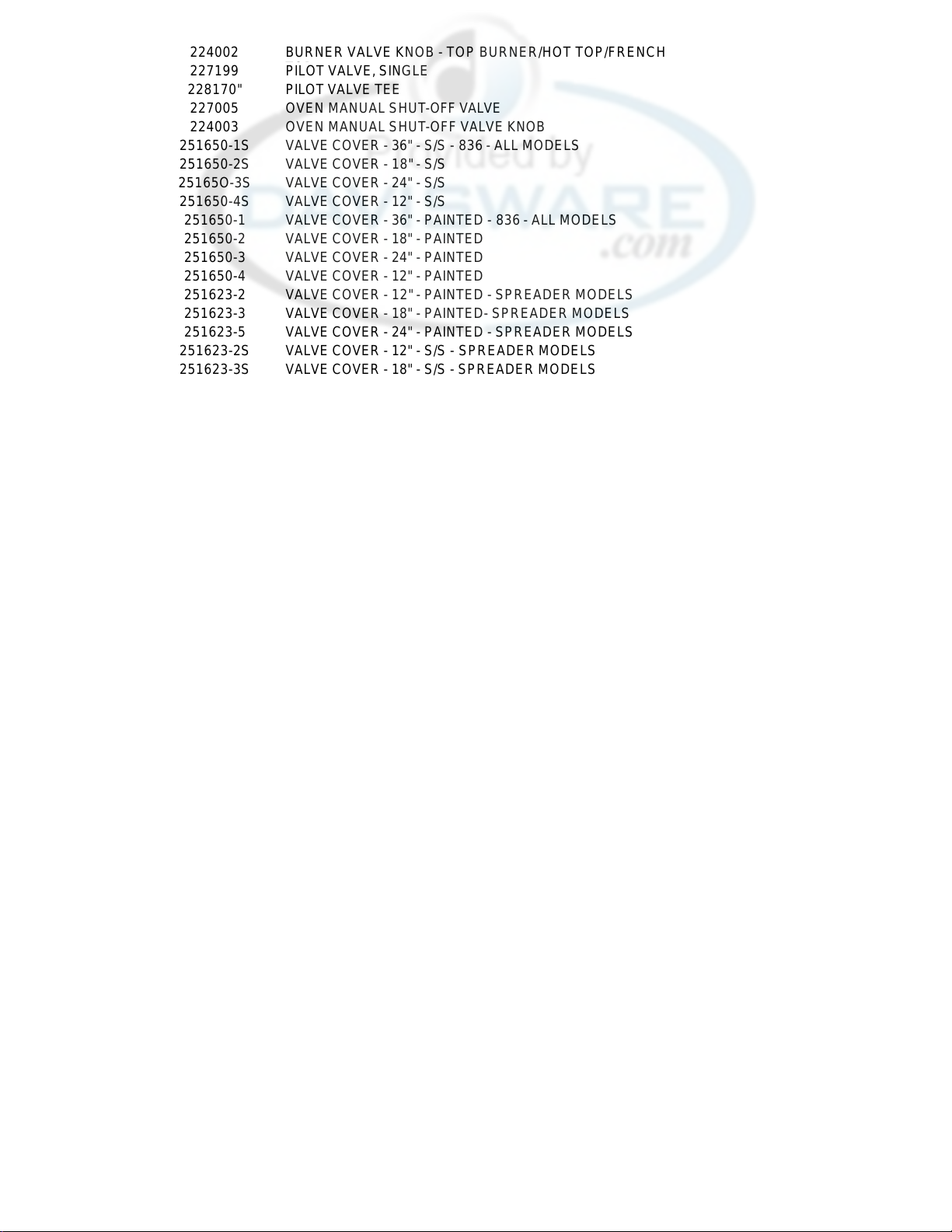
27 224002 BURNER VALVE KNOB - TOP BURNER/HOT TOP/FRENCH
28 227199 PILOT VALVE, SINGLE
29 227005 OVEN MANUAL SHUT -OFF VALVE
30 224003 OVEN MANUAL SHUT -OFF VALVE KNOB
31 251650-1S VALVE COVER - 36" - S/S - 836 - ALL MODELS
32 251623-2 VALVE COVER - 12" - PAINTED - SPREADER MODELS
33 251542-1 LANDING LEDGE - 836-1
34 MANIFOLD ASS'Y SPECIFY MODEL AND SERIAL NUMBER
34A
35 251539-1S CONTROL COVER - GRIDDLE - S/S
36 251531 SIDE TRIM
37 251599-1 DRIP PAN - 6 OPEN 8URNERS
38 251547-1 GRIDDLE GREASE CAN, L/H DRAIN, PAINTED
39 261483 OPEN BURNER HANGER
40 251600-1 OPEN BURNER, FRONT, COMPLETE
41 253133-3 PILOT TUBBING ASS'Y. GRIDDLE/HOT TOP
228170" PILOT VALVE TEE
251650-2S VALVE COVER - 18" - S/S
25165O-3S VALVE COVER - 24" - S/S
251650-4S VALVE COVER - 12" - S/S
251650-1 VALVE COVER - 36" - PAINTED - 836 - ALL MODELS
251650-2 VALVE COVER - 18" - PAINTED
251650-3 VALVE COVER - 24" - PAINTED
251650-4 VALVE COVER - 12" - PAINTED
251623-3 VALVE COVER - 18" - PAINTED- SPREADER MODELS
251623-5 VALVE COVER - 24" - PAINTED - SPREADER MODELS
251623-2S VALVE COVER - 12" - S/S - SPREADER MODELS
251623-3S VALVE COVER - 18" - S/S - SPREADER MODELS
251623-4S VALVE COVER - 24" - S/S - SPREADER MODELS
251623-5S VALVE COVER - 36" - S/S - SPREADER MODELS
251542-2 LANDING LEDGE - 1836-1
251543-1 LANDING LEDGE - 836-6, THRU -16
251543-2 LANDING LEDGE - 1836-7. -9. -16
251662-01 LANDING LEDGE - 836-2, -3
251662-02 LANDING LEDGE - 836-19
251662-03 LANDING LEDGE - 836-4. 15
251621-1S LANDING LEDGE END CAP, R/H, S/S
251621-2S LANDING LEDGE END CAP. L/H, S/S
223115 MANIFOLD PIPE CAP - 1 1/4"
223031-3 OPTIONAL INTAKE PIPE - 836-0836
223-31=8 OPTIONAL INTAKE PIP - 841-0841
251539-1 CONTROL COVER - GRIDDLE - PAINTED
251539-2S CONTROL COVER - ALL OTHER MODELS - S/S .
251539-2 CONTROL COVER - ALL OTHER MODELS - PAINTED
251599-2 DRIP PAN - 4 OPEN BURNERS. COMBINATION
251599-3 DRIP PAH - 2 OPEN BURNERS, COMBINATION
251648-1 DRIP PAH - 12" ADD-A-UNIT
251648-2 DRIP PAH - 18" ADD-A-UNIT
251648-3 DRIP PAH - 24" ADD-A-UNIT
251547-2 GRIDDLE GREASE CAN. L/H DRAIN. S/S
251782 GRIDDLE GREASE CAN - 0836/0841 MODELS
"SPECIAL" GRIDDLE GREASE CAN - R/H DRAIN
251600-2 OPEN BURNER, REAR, COMPLETE
222162 OPEN BURNER HEAD ONLY
222059 OPEN BURNER VENTURI, FRONT
222060 OPEN BURNER VENTURI, REAR
224005 GASKET. BURNER HEAD, FRONT/REAR
223005 AIR SHUTTER
18
Page 19
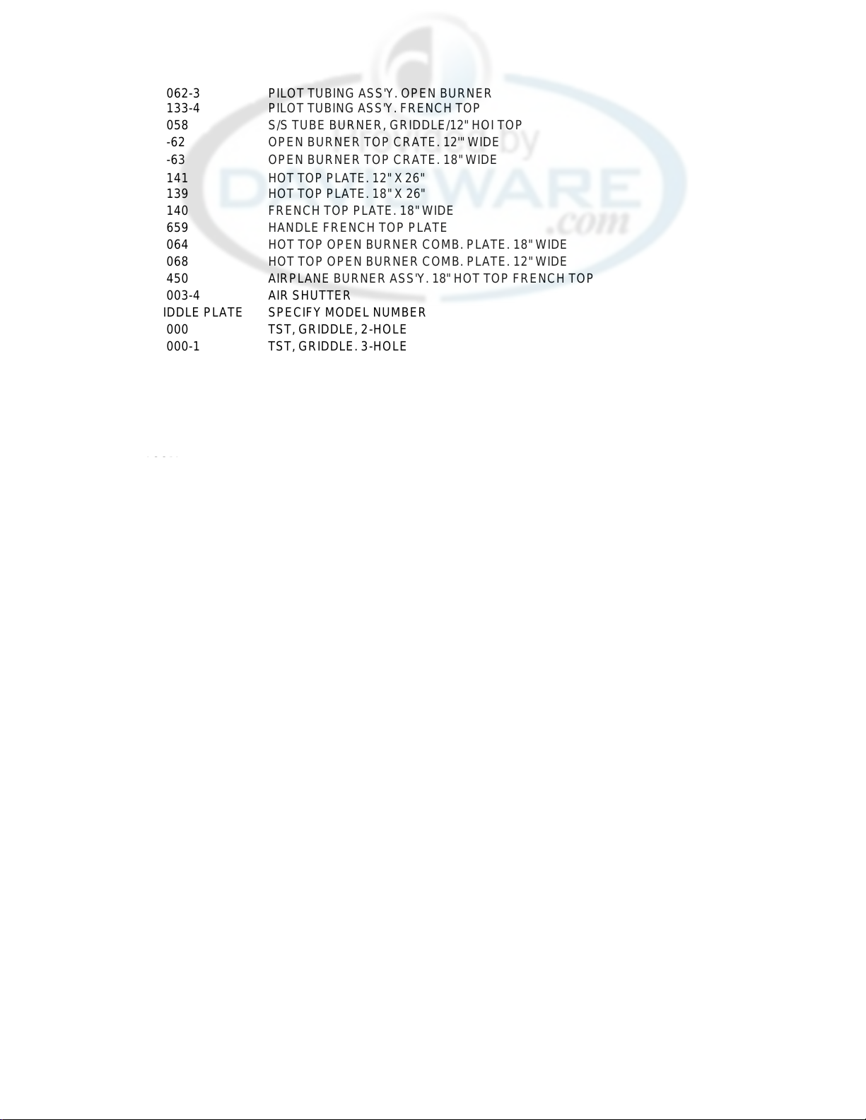
41A 253062-3 PILOT TUBING ASS'Y. OPEN BURNER
41B 253133-4 PILOT TUBING ASS'Y. FRENCH TOP
42 222058 S/S TUBE BURNER, GRIDDLE/12" HOI TOP
43 222-62 OPEN BURNER TOP CRATE. 12'" WIDE
43
222-63
44
222141
222139 HOT TOP PLATE. 18" X 26"
222140 FRENCH TOP PLATE. 18" WIDE
251659 HANDLE FRENCH TOP PLATE
222064 HOT TOP OPEN BURNER COMB. PLATE. 18" WIDE
222068 HOT TOP OPEN BURNER COMB. PLATE. 12" WIDE
251450 AIRPLANE BURNER ASS'Y. 18" HOT TOP FRENCH TOP
223003-4 AIR SHUTTER
45 GRIDDLE PLATE SPECIFY MODEL NUMBER
45A 227000 TST, GRIDDLE, 2-HOLE
227000-1 TST, GRIDDLE. 3-HOLE
229179 DIAL. TST. GRIDDLE
228112 BEZEL
225135 FASTENER
46 STUB BACK ASS'Y SPECIFY MODEL NUMBER. S/S OR PAINTED
47 HIGH SHELF ASS'Y SPECIFY MODEL NUMBER S/S OR PAINTED
48 DOUBLE SHELF
49 228052-9 PRESSURE REGULATOR. 1 1/4, HAT
228052-12 PRESSURE REGULATOR, 1 1/4. PROPANE
228052-13 PRESSURE REGULATOR. 3/4, HAT
228052-14 PRESSURE REGULATOR. 3/4, PROPANE
50 223242-48 BURNER ORIFICE HOOD, HAT - 12" HOT TOP
223242-56 223242-
38
223242-52 BURNER ORIFICE HOOD, PRO PANE - 18" HOT TOP/FRENCH TOP
51 222140-1 LID/FRENCH TOP
222140-2 RING/FRENCH TOP
222140-3 CASTING ONLY - FRENCH "TOP
OPEN BURNER TOP CRATE. 18" WIDE
HOT TOP PLATE. 12" X 26"
SPECIFY MODEL NUMBER S/S OR PAINTED
BURNER ORIFICE HOOD, PROPANE - 12" HOT TOP
BURNER:ORIFICE HOOD, HAT - 18" HOT TOP/FRENCH TOP
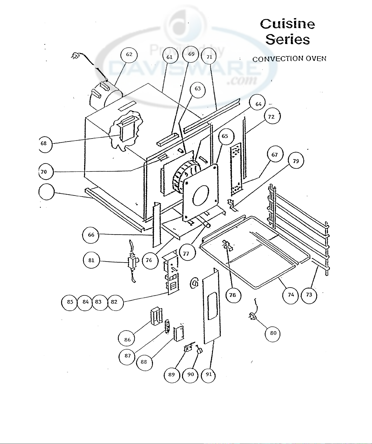
CUISINE SERIES - 836 CONVECTION OVEN
61 261530-1 OVEN TONIC ASS'Y
62 228129 MOTOR
63 261539 MOTOR MTG PAD ASS'Y
261590-2 SPACER
225213 B0LT
225053-1 NUT
64 228130 BLOWER WHEEL
65 251543-1 BLOWER COVER
66 261570-1 L/H BAFFLE ASS'Y
67 261569-1 R/H BAFFLE ASS'Y
68 261545-1 FLUE SPOUT ASS'Y
69 261599-1 FLUE INTAKE TUBE ASS'Y
70 259039 CAPILLARY HOLDER
71 252817-1 TOP DOOR GASKET
252817-2 BOTTOM DOOR GASKET
72 252819-1 R/H DOOR GASKET
252819-2 L/H DOOR GASKET
75 226018 RACK SUPPORT
74 226019 WIRE RACK
75 261534 FLAME DEFLECTOR
76 261563 BURNER DOOR ASS'Y
19
Page 20
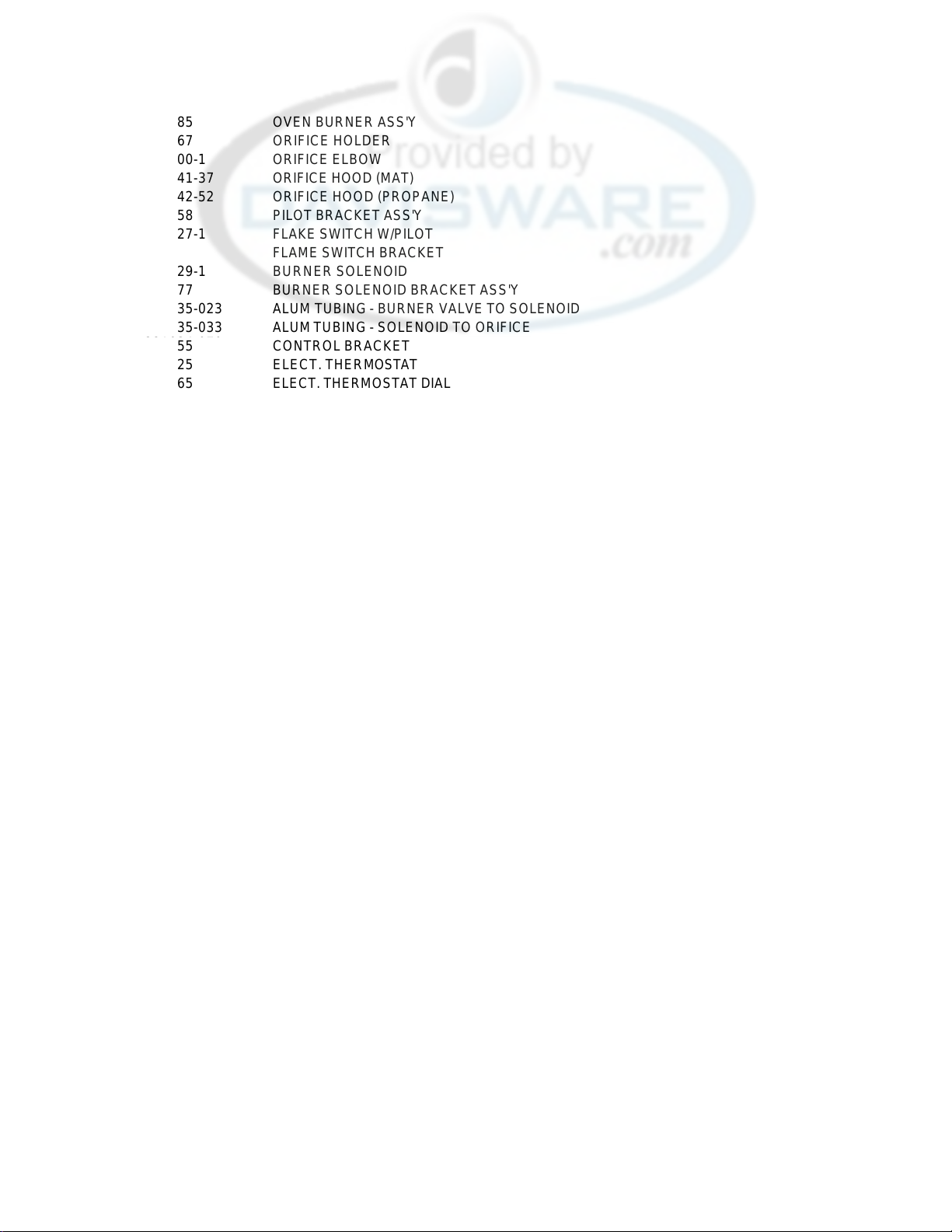
77 261585 OVEN BURNER ASS'Y
78 261567 ORIFICE HOLDER
223000-1 ORIFICE ELBOW
223241-37 ORIFICE HOOD (MAT)
223242-52 ORIFICE HOOD (PROPANE)
79 261558 PILOT BRACKET ASS'Y
80 227027-1 FLAKE SWITCH W/PILOT
81 227029-1 BURNER SOLENOID
261577 BURNER SOLENOID BRACKET ASS'Y
221035-023 ALUM TUBING - BURNER VALVE TO SOLENOID
221035-033
82 261555 CONTROL BRACKET
83 227025 ELECT. THERMOSTAT
224065 ELECT. THERMOSTAT DIAL
84 228006-1 FAN MOTOR SWITCH
85 228007-1 RED INDICATOR LIGHT
228007-2 AMBER INDICATOR LIGHT
86 261556 TERMINAL BOX
87 228000 TERMINAL BLOCK
88 261587 TERMINAL BOX COVER
89 227034 MICRO SWITCH
90 252706 SWITCH CAN ASS'Y
91 261572-1 FACE PLATE ASS'Y (FRY TOP)
261573-2 FACE PLATE ASS'Y (STD)
FLAME SWITCH BRACKET
ALUM TUBING - SOLENOID TO ORIFICE
20
 Loading...