

U.S. Products TREADMASTER User Manual
EN
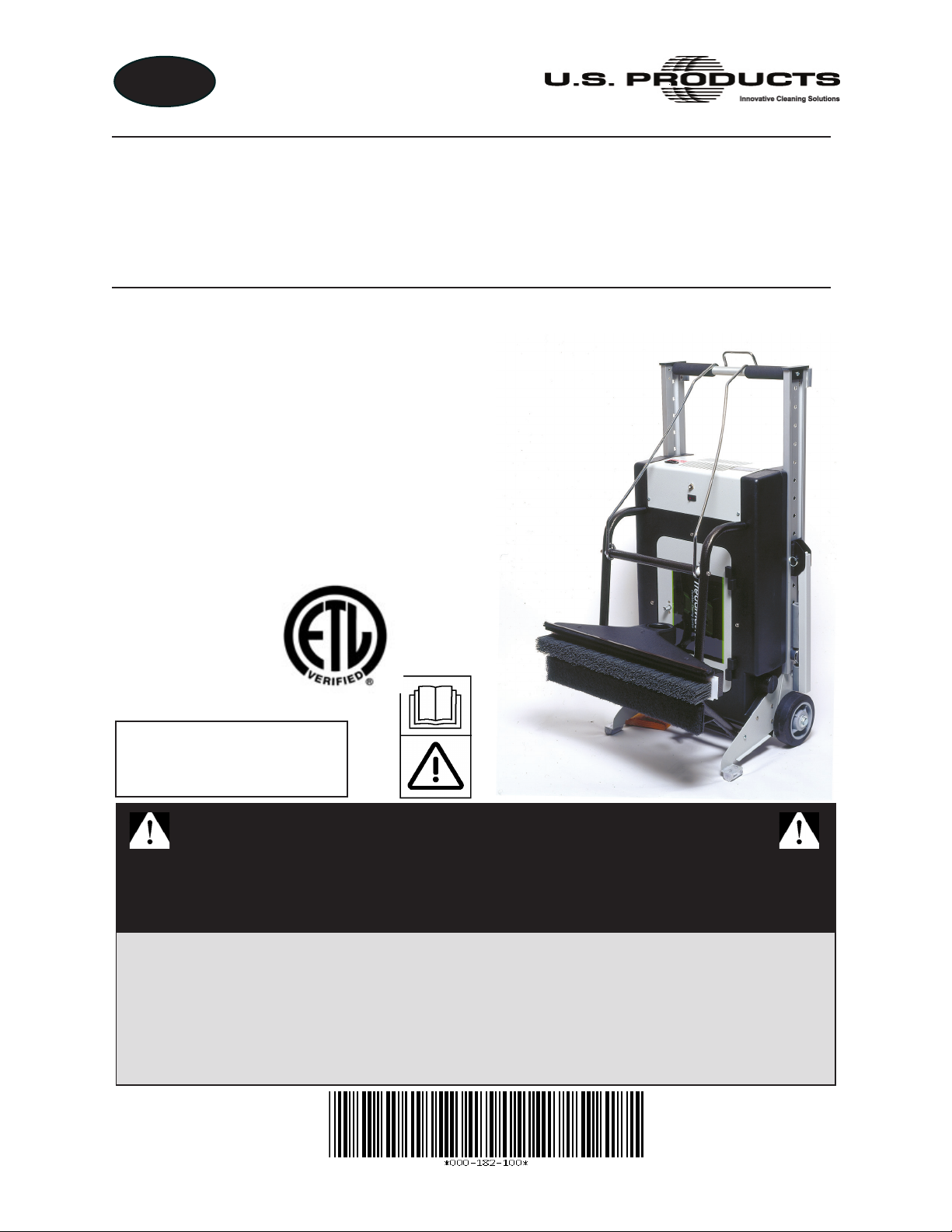
TREADMASTER™
ESCALATOR
CLEANER
INFORMATION AND
OPERATING
INSTRUCTIONS
Models 100-100-001
100-100-002
100-100-003
100-100-004
100-100-005
Models 100-100-221
100-100-222
100-100-223
SAVE THESE
INSTRUCTIONS
IMPORTANT SAFETY INSTRUCTIONS
When using an electrical appliance, basic precautions should always
be followed, including the following:
READ ALL INSTRUCTIONS BEFORE USING THE TREADMASTER
U.S. Products
11015 47th Avenue West, Mukilteo, Washington 98275
MAN-44183 Rev. E, July 3, 2014
(P/N 000-182-100)
No part of this manual may be reproduced or used in any form or by any means (i.e. graphic, electronic, photocopying
or electronic retrieval systems) without the express written permission of U.S. Products. Specications and information in this
document are subject to change without prior notice.
All rights reserved. © 2014
U.S. Products

EN
EN
FR
= ENGLISH (120 V/230 V)
= CANADIAN FRENCH (120 V)

EN
Table of Contents
GENERAL INFORMATION ............................................................................................. 1
Approvals/Certications ............................................................................................. 3
Contact Information .................................................................................................... 4
Warnings, Cautions and Notices ................................................................................ 4
MACHINE SPECIFICATIONS ......................................................................................... 9
TreadMaster Options and Accessories .................................................................... 10
MEASURING INFORMATION ...................................................................................... 11
INSPECTION, INSTALLATION AND TRANSPORTING .............................................. 13
Installing New Head Assembly ................................................................................. 13
Inserting a Different Brush into Head Assembly ....................................................... 15
Transporting/storing the TreadMaster ...................................................................... 16
GROUNDING INSTRUCTIONS .................................................................................... 17
OPERATING INSTRUCTIONS ..................................................................................... 19
Preparation............................................................................................................... 19
Operation ................................................................................................................. 22
Polishing ................................................................................................................. 23
Touch-Up Cleaning Hints ......................................................................................... 23
DAILY MAINTENANCE ................................................................................................. 25
Refreshing and Replacing the Brush ....................................................................... 25
Replacing the Polishing Pad .................................................................................... 25
Using the Riser Brush .............................................................................................. 25
Cleaning the Vacuum Bag ........................................................................................ 26
ELECTRICAL SYSTEM ................................................................................................ 27
i - TreadMaster Information and Operating Instructions

EN
ASSEMBLIES AND PARTS LISTS .............................................................................. 33
Parts and Support .................................................................................................... 33
Congurations .......................................................................................................... 34
Frame Housing Assembly (120V) Parts List ............................................................ 38
24” Nylon Grit Head Assembly ................................................................................. 40
32” Nylon Grit Head Assembly ................................................................................. 42
40” Nylon Grit Head Assembly ................................................................................. 44
22” Nylon Grit Head Assembly ................................................................................. 46
37” Nylon Grit Head Assembly ................................................................................. 48
Left Rail and Heel Plate Assembly Parts List ........................................................... 50
Right Rail and Heel Plate Assembly Parts List......................................................... 52
Left Extension Arm Assembly Parts List................................................................... 53
Right Extension Arm Assembly Parts List ................................................................ 54
Lift Arm Assembly Parts List..................................................................................... 55
Escalator Cleaning Safety Sign Assembly Parts List ............................................... 56
Wheels and Jack Assembly Parts List ..................................................................... 58
Door Assembly Parts List ......................................................................................... 59
Motor Housing Assembly Parts List ......................................................................... 60
Housing Support Assembly Parts List ...................................................................... 61
Vacuum Motor (120V) Assembly Parts List .............................................................. 62
WARRANTY INFORMATION ........................................................................................ 63
TreadMaster Information and Operating Instructions - ii

EN
List of Figures
Figure 1. Accurate Measurements Needed Before
Ordering Brush and Head Assembly ...........................................................11
Figure 2. Position Assemblies Together, on Flat Surface ............................................. 13
Figure 3. Fluted Knobs Removed from Head Assembly; Nozzle Facing Outward ....... 13
Figure 4. Position Pad Holder Lift Arm on Head Assembly .......................................... 14
Figure 5. Secure Head Assembly with Fluted Knobs; Attach Hose to Nozzle .............. 14
Figure 6. Attach Other End of Hose to Housing Assembly ........................................... 14
Figure 7. Loosen Thumb Screw and Slide Brush Out of Head Assembly .................... 15
Figure 8. Attach Latching Bail Handle to Housing Assembly’s Handle
and Position TreadMaster in Upright Position ........................................... 16
Figure 9. TreadMaster Shown in Upright Position ........................................................ 19
Figure 10. TreadMaster Shown in Preferred Placement, at Bottom of Escalator ......... 19
Figure 11. TreadMaster Shown in Flat Position ............................................................ 19
Figure 12. Components of TreadMaster ....................................................................... 20
Figure 14. Location of Cleaning
Head Level ................................................................................................ 21
Figure 13. Ensure Restraining Arms are Firmly Seated Against Balustrades .............. 21
Figure 15. Adjust Depth of Cleaning Head with Fluted Knobs ..................................... 21
Figure 16. Set Lift Arm in Up Position........................................................................... 22
Figure 17. Vertical Face of Escalator is Riser............................................................... 25
Figure 18. TreadMaster Wiring Diagram – 120 V (Power Circuit) ................................ 28
Figure 19. TreadMaster Wiring Diagram – 120 V (Ground Circuit) .............................. 29
Figure 20. TreadMaster Electrical Schematic – 120 V ................................................. 30
Figure 21. TreadMaster Wiring Diagram – 230 V ......................................................... 31
Figure 22. TreadMaster Electrical Schematic – 230 V ................................................. 32
Figure 23. Adhesive/Sealant Material Reference ......................................................... 35
Figure 24. Frame Housing Assembly (120V) - View 1 of 2 ........................................... 36
Figure 25. Frame Housing Assembly (120V) - View 2 of 2 ........................................... 37
Figure 26. 24” Nylon Grit Head Assembly .................................................................... 39
Figure 27. 32” Nylon Grit Head Assembly .................................................................... 41
Figure 28. 40” Nylon Grit Head Assembly .................................................................... 43
Figure 29. 22” Nylon Grit Head Assembly .................................................................... 45
iii - TreadMaster Information and Operating Instructions

EN
Figure 30. 37” Nylon Grit Head Assembly ..................................................................... 47
Figure 31. Left Rail and Heel Plate Assembly ............................................................... 49
Figure 32. Right Rail and Heel Plate Assembly ............................................................. 51
Figure 33. Left Extension Arm Assembly ....................................................................... 53
Figure 34. Right Extension Arm Assembly .................................................................... 54
Figure 35. Lift Arm Assembly ......................................................................................... 55
Figure 36. Escalator Cleaning Safety Sign Assembly ................................................... 56
Figure 37. Wheels and Jack Assembly.......................................................................... 57
Figure 38. Door Assembly ............................................................................................. 59
Figure 39. Motor Housing Assembly.............................................................................. 60
Figure 40. Housing Support Assembly .......................................................................... 61
Figure 41. Vacuum Motor (120V) Assembly .................................................................. 62
List of Tables
Table 1. TreadMaster Congurations - 120V ................................................................. 34
Table 2. TreadMaster Congurations - 230V ................................................................. 34
TreadMaster Information and Operating Instructions - iv
EN
GENERAL INFORMATION
The TreadMaster is a specialized machine designed to clean escalators and moving
sidewalks (horizontal “people movers”) in commercial establishments such as airports,
hotels, shopping malls, schools, hospitals, factories, shops and ofces.
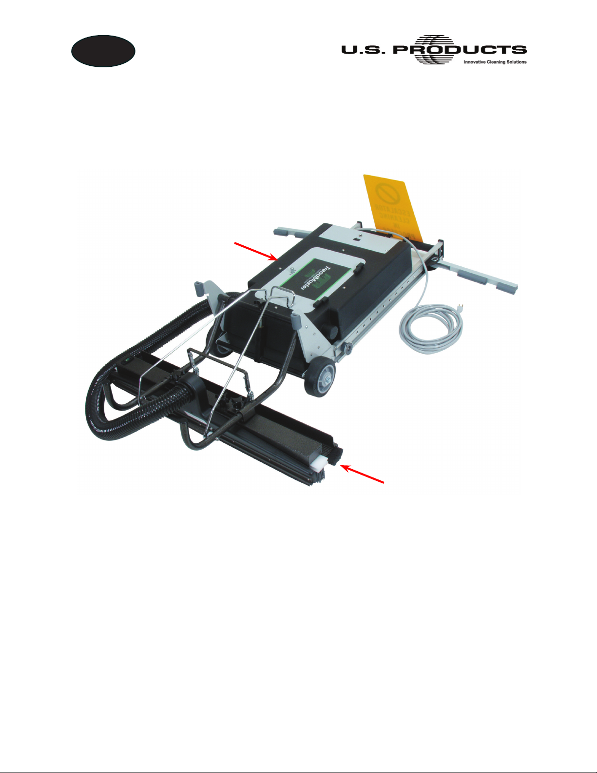
Housing Assembly
Head Assembly
It is simple to set up and automatic in its operation. The TreadMaster’s weighted head
assembly ts down into the tread of the escalator to loosen soil and debris. A vacuum
chamber and nozzle collects and deposits the loose debris in a vacuum bag, which is
located in the housing assembly. A polishing pad then nishes cleaning the top of the
tread.
The TreadMaster is available in ve basic head assemblies, and can also be custom built
according to the step width of your escalator or moving walkway. The same housing can
be used or interchanged with any of the custom-sized head assemblies. See Table 1 and
Table 2 on page 34 for detailed conguration information.
1 - TreadMaster Information and Operating Instructions

EN
This document contains operation instructions as well as information required for proper
maintenance of the TreadMaster. It is the purpose of this document to help you properly
understand, maintain and service your TreadMaster. Follow the directions carefully and
you will be rewarded with years of protable, trouble-free operation.
It is imperative that no section of this document be overlooked when operating and
maintaining the TreadMaster. Please read the contents to familiarize yourself with the
operation of your TreadMaster, paying special attention to all Warnings and Cautions.
TreadMaster Information and Operating Instructions - 2

EN
APPROVALS/CERTIFICATIONS
CSA Approved
Your machine has been designed and tested to comply with the Canadian standard for
this class of equipment. It has been tested under the following standard:
CSA C22.2#243
Issue:2001/12/07 Ed. 3 Rev:2001/06/15 Vacuum Cleaners, Blower Cleaners, and
Household Floor Finishing Machines; General Instruction No 1; UL 1017 (R2006)
If it is necessary to provide verication, your machine is labeled with an ETL mark.
Do not remove or tamper with any part of the TreadMaster; this may result in a
non-compliance with the above standard.
3 - TreadMaster Information and Operating Instructions
EN
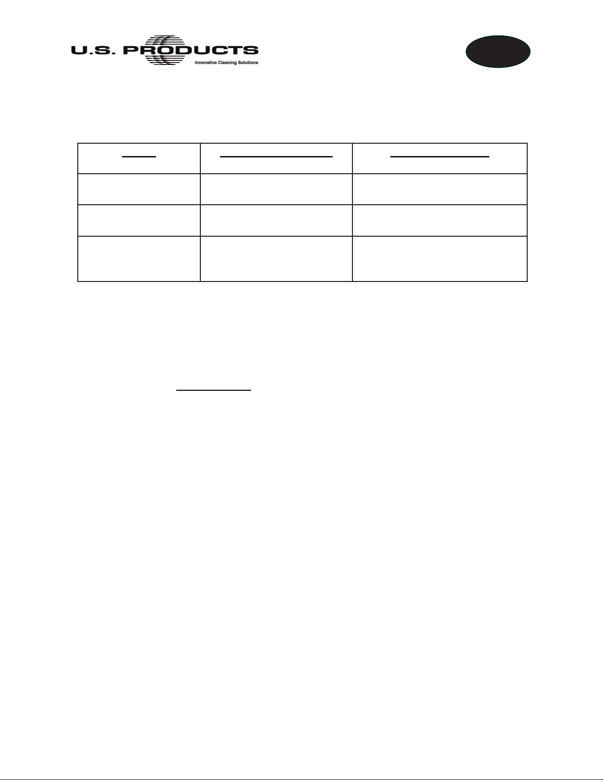
CONTACT INFORMATION
If you have any questions regarding the operation, maintenance or repair of this machine,
refer to the following information and contact the appropriate U.S. Products department.
Hours Telephone Numbers E-mail Addresses
Monday-Friday (425) 322-0133 Support
7:00 a.m. to
5:00 p.m.
Pacic Time
When calling or contacting us, be sure to reference the serial number and date of purchase.
FOR YOUR REFERENCE
Model: TreadMaster
Serial Number: __________________
Purchase Date:_____________
Name and phone number of your distributor:
(800) 257-7982 Parts
FAX
(425) 322-0136
techsupport@usproducts.com
csorders@usproducts.com
Tech Support:
Parts Support:
_____________________________________
_____________________________________
TreadMaster Information and Operating Instructions - 4

EN
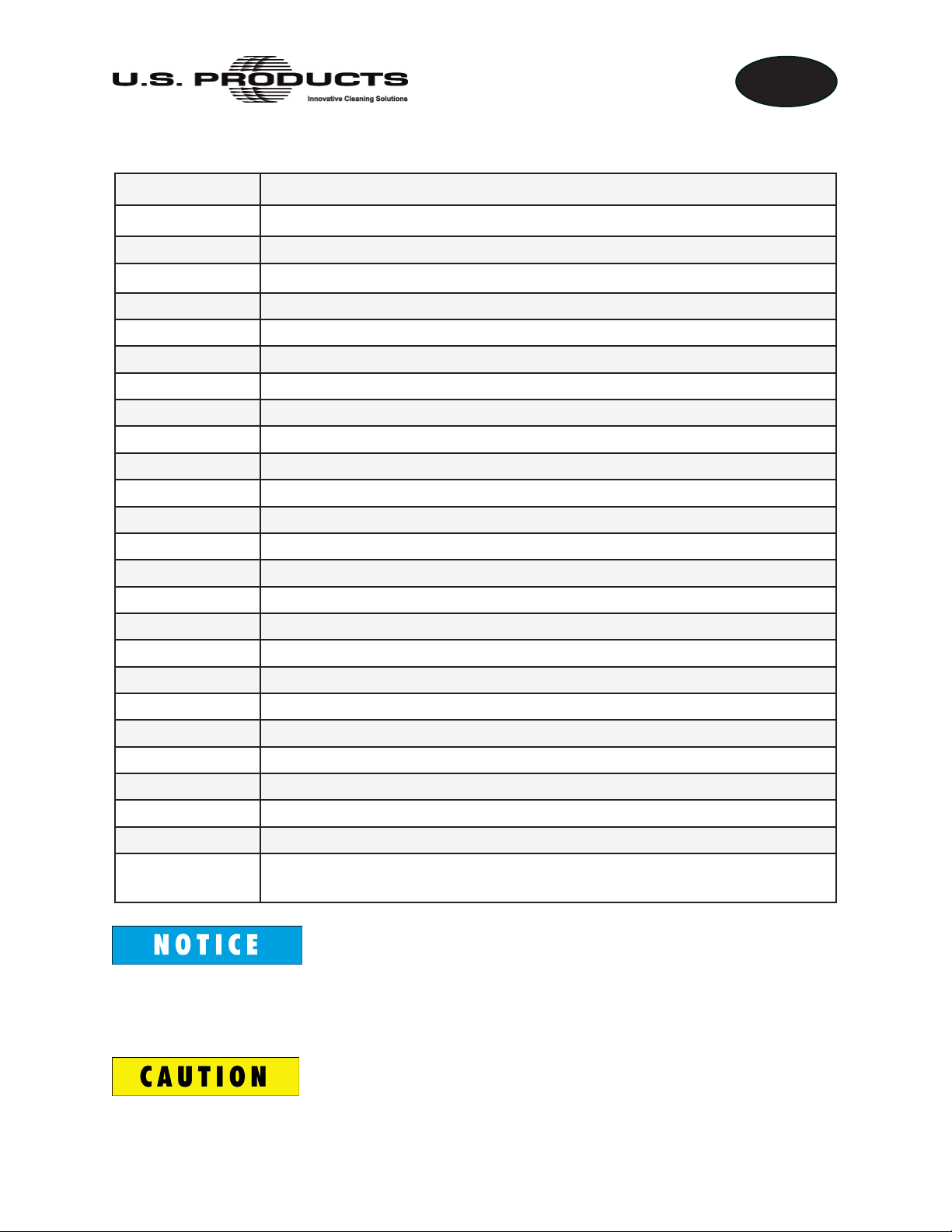
WARNINGS, CAUTIONS AND NOTICES
U.S. Products uses this WARNING symbol throughout this document to warn of
possible injury or death.
This CAUTION symbol is used to warn of possible equipment damage.
This NOTICE symbol indicates that federal or state regulatory laws may apply,
and also emphasizes supplemental information.
5 - TreadMaster Information and Operating Instructions

EN
Warnings and Cautions specic to the TreadMaster include the following. To reduce the
risk of re, electric shock, or injury:
Turn off all controls before unplugging the TreadMaster. Failure to do so can
cause bodily injury.
Unplug the TreadMaster from outlet when it is not in use and before servicing.
Failure to do so can cause bodily injury.
Do not unplug the TreadMaster by pulling on its cord. To unplug, grasp the plug,
not the cord. Failure to follow this warning can result in a damaged power cord,
leading to the possibility of electric shock and serious bodily injury or death.
Do not handle the plug or the TreadMaster with wet hands. Failure to follow this
warning can cause bodily injury.
Do not use the TreadMaster outdoors (except in arenas or stadiums) or on wet
surfaces. This machine is for dry use only and shall not be used or stored in
uncovered outdoor venues or in wet conditions. Failure to follow this warning can
cause bodily injury.
Do not allow anyone to sit or stand on the TreadMaster. Failure to follow this
warning can cause bodily injury.
Do not allow to be used as a toy. Close attention is necessary when used near
children.
Use the TreadMaster only as described in this manual. Use only manufacturer’s
recommended attachments. Failure to do so can cause bodily injury.
TreadMaster Information and Operating Instructions - 6

EN
Do not use with damaged cord or plug. If appliance is not working as it should,
has been dropped, damaged, left outdoors, or dropped into water, return it to a
service center. Failure to follow this warning can result in the possibility of electric
shock, serious bodily injury and/or death.
Do not pull or carry by cord, use cord as a handle, close a door on cord, or pull
cord around sharp edges or corners. Do not run appliance over cord. Keep cord
away from heated surfaces. Failure to follow this warning can result in a damaged
power cord, leading to the possibility of electric shock and serious bodily injury
or death.
Do not put any object into openings. Do not use with any opening blocked; keep
free of dust, lint, hair, and anything that may reduce air ow. This machine is not
suitable for accumulating, gathering or otherwise picking up health-endangering
dust. Failure to follow this warning can cause bodily injury.
Keep hair, loose clothing, ngers, and all parts of body away from openings and
moving parts. Failure to do so can cause bodily injury.
Do not use without vacuum bag and/or lters in place. Failure to follow this
warning can cause bodily injury.
Do not use to pick up ammable or combustible liquids, such as gasoline, or use
in areas where they may be present. Failure to follow this warning can lead to the
possibility re and/or explosion. This can result in serious bodily injury or death.
Do not pick up anything that is burning or smoking, such as cigarettes, matches,
or hot ashes. Failure to follow this warning can lead to the possibility re and/or
explosion. This can result in serious bodily injury or death.
7 - TreadMaster Information and Operating Instructions

EN
Before setting up the machine, turn off the escalator or moving sidewalk. Failure
to do so can cause bodily injury.
This appliance must be grounded. Connect to a properly grounded outlet only.
See Grounding Instructions on page 17 of this document. Failure to properly
ground the equipment can result in the possibility of electric shock and serious
bodily injury or death.
If the plug on the power cord is damaged, dispose of the cord. To prevent possible
electric shock, DO NOT insert the damaged plug into an electrical socket. Failure
to follow this warning can result in the possibility of electric shock and serious
bodily injury or death.
Use extra care when cleaning on stairs.
Match the size of the TreadMaster head assembly to the size of the step you are
cleaning. Do not use a 24” head to clean a 32” or 40” step.
Always place the TreadMaster where the steps are moving away from the unit.
The TreadMaster can be operated from the top or the bottom of the escalator;
however, bottom placement is preferred.
The power cord for the following models is not supplied by the manufacturer; it
must be supplied by the operator:
• 100-100-221
• 100-100-222
• 100-100-223
TreadMaster Information and Operating Instructions - 8

EN
MACHINE SPECIFICATIONS
Housing Assembly
Dimensions
Housing Assembly
Weight
Brush and
Head Assembly
Dimensions and
Weight
21.5” W x 31.5” L x 47” H (55 cm W x 80 cm L x 119 cm H)
84 lbs (38 kg)
22” Head
24” Head
32” Head
37” Head
40” Head
7” W x 22” L x 10” H
(18 cm W x 56 cm L x 25 cm H)
7” W x 24” L x 10” H
(18 cm W x 61 cm L x 25 cm H)
7” W x 32” L x 10” H
(18 cm W x 81 cm L x 25 cm H)
7” W x 37” L x 10” H
(18 cm W x 94 cm L x 25 cm H)
7” W x 40” L x 10” H
(18 cm W x 102 cm L x 25 cm H)
58 lbs
(26 kg)
58 lbs
(26 kg)
69 lbs
(31 kg)
80 lbs
(36 kg)
80 lbs
(36 kg)
Vacuum Motor Two 1 5/8 HP motors
Power Consumption 120 V AC 230 V AC
12 Amps 6.8 Amps
50/60 Hz 50/60 Hz
1,440 Watts 1,564 Watts
Construction Durable rotomolded housing - Polyethylene UL-94V2 Rated
Two nonmarking rubber wheels
Extruded aluminum frame
9 - TreadMaster Information and Operating Instructions
TREADMASTER OPTIONS AND ACCESSORIES
Part Number Description
190-100-014 Head Assembly, 22” w/ Nylon Grit Brush
190-100-011 Head Assembly, 24” w/ Nylon Grit Brush
190-100-012 Head Assembly, 32” w/ Nylon Grit Brush
190-100-015 Head Assembly, 37” w/ Nylon Grit Brush
190-100-013 Head Assembly, 40” w/ Nylon Grit Brush
190-100-002 TreadMaster Housing (120 V)
190-100-201 TreadMaster Housing (230 V)
101-100-028 Spare Brush, 22” and 24” Nylon Grit
101-100-029 Spare Brush, 32” Nylon Grit
101-100-030 Spare Brush, 37” and 40” Nylon Grit
105-100-018 Nozzle Assembly, 24” Vacuum
105-100-019 Nozzle Assembly, 32” Vacuum
EN
105-100-020 Nozzle Assembly, 40” Vacuum
000-016-062 Brush, Vacuum 24”
000-016-063 Brush, Vacuum 32”
000-016-064 Brush, Vacuum 40”
000-016-060 Escalator Riser Brush
101-100-031 Spare Soft Brush for Painted Escalators, 22” and 24”
101-100-032 Spare Soft Brush for Painted Escalators, 32”
101-100-033 Spare Soft Brush for Painted Escalators, 37” and 40”
000-078-201 Spare Polishing Pads, 22” and 24” (6 per case)
000-078-203 Spare Polishing Pads, 32” (6 per case)
000-078-205 Spare Polishing Pads, 37” and 40” (6 per case)
000-049-115 Vacuum Bag, Cloth (each)
000-031-105 Escalator Tread Spot Cleaner, Case
(10 oz. [0.3 litre] aerosol cans, 6 cans per case)*
*U.S. Products’s Escalator Tread Spot Cleaner is a fast acting spot cleaner designed
specially for use on aluminum escalator steps. Spot Cleaner is non-ammable
and non-conductive so it can be used while the TreadMaster is operating.
Use of any other chemical may clog components and could void the warranty.
TreadMaster Information and Operating Instructions - 10
EN
MEASURING INFORMATION
Before ordering an additional or replacement head assembly, be aware that specic
measurements are needed to effectively and efciently process your order.
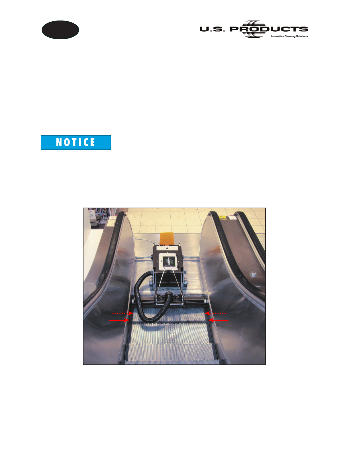
To properly measure the escalator or moving sidewalk, refer to Figure 1 and follow these
guidelines:
1. With a measuring device, measure the horizontal distance from side wall to side
wall, on the bottom step (see solid arrows in Figure 1).
If safety brushes are installed on the escalator or moving sidewalk, measure the
horizontal distance from brush tip to brush tip, on the bottom step (see dashed
arrows in Figure 1).
2. Subtract 1/2” from the measurement. This is the number you will be asked to
provide when you place your order.
Figure 1. Accurate Measurements Needed Before
Ordering Brush and Head Assembly
If you have any questions or need more information about the measuring process, contact
U.S. Products Sales at 1-800-257-7982.
11 - TreadMaster Information and Operating Instructions

EN
TreadMaster Information and Operating Instructions - 12
EN
INSPECTION, INSTALLATION AND
TRANSPORTING
INSPECTING ASSEMBLIES
After receiving your TreadMaster, carefully unpack the boxes and inspect the housing
assembly, brush and head assembly for shipping damage.
No matter which TreadMaster conguration you order (see Table 1 and Table 2 on
34), you can receive up to three major assemblies in your shipment unless you specify
otherwise:
1. Soft Brush for Painted Escalators
2. Housing Assembly
3. Head Assembly
Each machine is tested and inspected before being shipped. Any shipping damage incurred
is the responsibility of the carrier. You should notify the carrier immediately if you notice
damage to the box, to the machine or any parts.
INSTALLING NEW HEAD ASSEMBLY
For the initial setup, install the head assembly by:
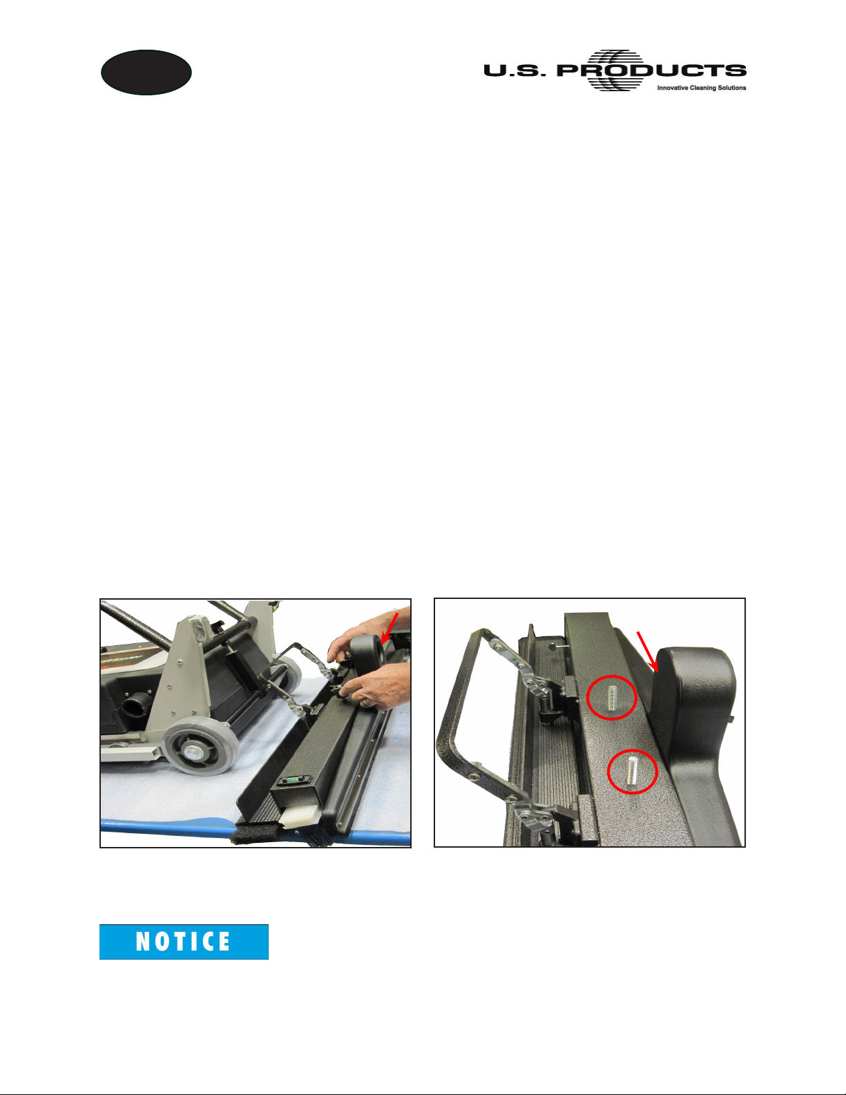
1. Placing the head assembly and housing assembly on a at surface (see Figure 2).
2. Unfastening the two uted knobs on the head assembly (see Figure 2 and Figure 3).
Nozzle
Figure 2. Position Assemblies
Together, on Flat Surface
Figure 3. Fluted Knobs Removed
from Head Assembly; Nozzle Facing
Outward
Note that the nozzle opening is facing outward during installation.
13 - TreadMaster Information and Operating Instructions
EN
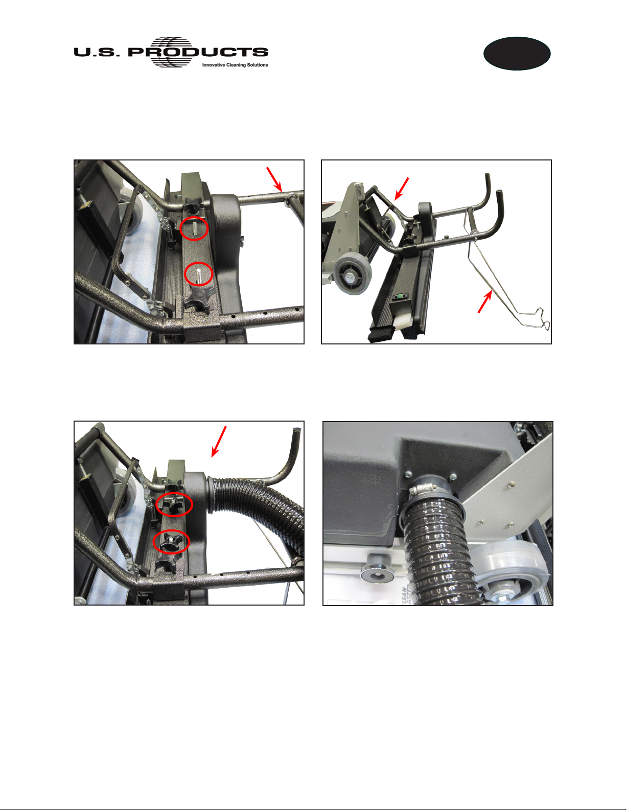
3. Position the housing assembly’s lift arm onto the head assembly, aligning the
mounting holes on the lift arm with the fasteners on the head assembly (see
Figure 4).
Lift Arm
Lift Arm
Latching Bail
Handle
Figure 4. Position Pad Holder Lift Arm on Head Assembly
4. Secure the head assembly to the lift arm by re-installing the two uted knobs (see
Figure 5).
Figure 5. Secure Head Assembly
with Fluted Knobs;
Figure 6. Attach Other End of Hose to
Housing Assembly
Attach Hose to Nozzle
5. Attach the vacuum hose between the housing and the cleaning nozzle. The hose
connector with the shorter end should be connected to the cleaning nozzle assembly
(see Figure 5). The hose connector with the longer end is connected to the housing
(see Figure 6) and should be secured by tightening the clamp.
TreadMaster Information and Operating Instructions - 14
EN
INSERTING A DIFFERENT BRUSH INTO HEAD ASSEMBLY
If you want to replace a brush — for example, in the case of removing the nylon grit brush
and replacing it with the Soft brush for painted escalators — follow these steps:
1. Turn off the TreadMaster.
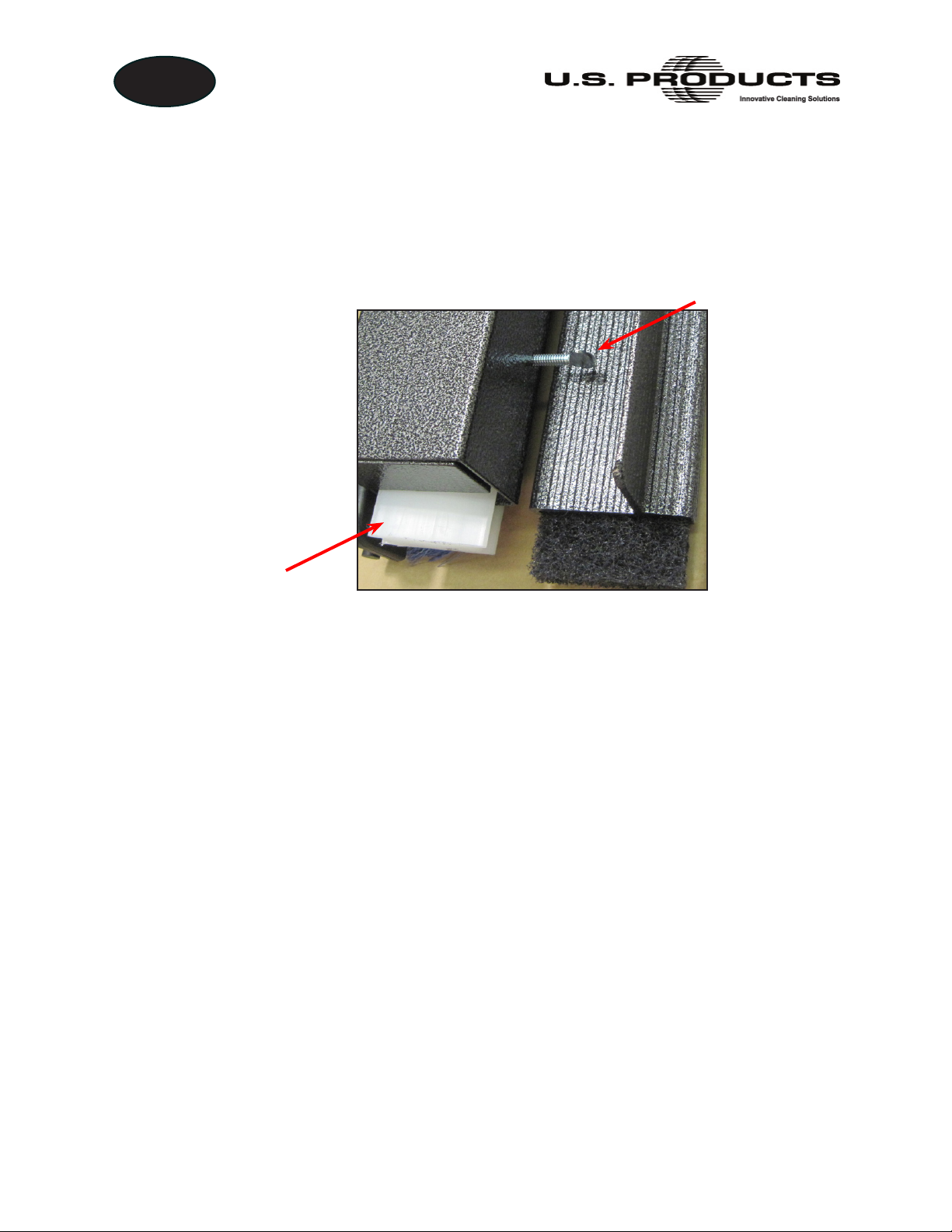
2. Loosen the thumb screw on the head assembly (see Figure 7).
Thumb Screw
Slide Brush Out of
Head Assembly
Figure 7. Loosen Thumb Screw and Slide Brush Out of Head Assembly
3. Slide the brush out of the head assembly.
4. Insert the new brush.
5. Tighten the thumb screw.
6. Turn on the TreadMaster and resume cleaning.
15 - TreadMaster Information and Operating Instructions
 Loading...