

Page 1

NIDEC MOTOR CORPORATION
8050 WEST FLORISSANT AVE.
ST. LOUIS, MO 63136
DATE: 1/26/2021 P.O. NO.: FD15
Order/Line NO.: 23176 MN 100
TO:
Model Number: FD15
Catalog Number: U2P2DC
Unimount Pre. Eff. Config.
CONF,MOTOR,UNIMOUNT PRE EFF
REVISIONS:
(NONE)
ALL DOCUMENTS HEREIN ARE CONSIDERED CERTIFIED BY NIDEC MOTOR CORPORATION.
THANK YOU FOR YOUR ORDER AND THE OPPORTUNITY TO SERVE YOU.
Features:
Horsepower .............. 00002.00 ~ KW: 1.492
Enclosure ............... TEFC
Poles ................... 04 ~ RPM: 1800
Frame Size .............. 145~TC
Phase/Frequency/Voltage.. 3~060~230/460-208 ~ Random Wound
Service Factor .......... 1.25
Insulation Class ........ Class "F" ~ Insulife 1000
Altitude In Feet (Max) .. 3300 Ft.(1000 M)
Ambient In Degree C (Max) +40 C
Assembly Position ....... "F-1" Assembly Position
Efficiency Class ........ Premium Efficiency
Application ............. Unknown
Customer Part Number ....
Secondary Rating:
2 Horsepower ~ 50 Hertz ~ 190/380 Volts
"AK" Dimension (Inches).. 4.500
Temperature Rise (Sine Wave): "B" Rise @ 1.0 SF (Resist)
Starting Method ......... Direct-On-Line Start
Duty Cycle .............. Continuous Duty
Efficiency Value ........ 86.5 % ~ Typical
Load Inertia (lb-ft2): NEMA ~ NEMA Inertia: 11.00 ~ 1.00
Number Of Starts Per Hour: NEMA
Motor Type Code ......... UTE
Rotor Inertia (LB-FT²) .122 LB-FT²
Qty. of Bearings PE (Shaft) 1
Qty. of Bearings SE (OPP) 1
Bearing Number PE (Shaft) 6205-2Z-J/C3
Bearing Number SE (OPP) 6203-2Z-J/C3
Nidec trademarks followed by the ® symbol are registered with the U.S. Patent and Trademark Office.
Page 2

NIDEC MOTOR CORPORATION
8050 WEST FLORISSANT AVE.
ST. LOUIS, MO 63136
DATE: 1/26/2021 P.O. NO.: FD15
Order/Line NO.: 23176 MN 100
TO:
Model Number: FD15
Catalog Number: U2P2DC
Unimount Pre. Eff. Config.
CONF,MOTOR,UNIMOUNT PRE EFF
REVISIONS:
(NONE)
ALL DOCUMENTS HEREIN ARE CONSIDERED CERTIFIED BY NIDEC MOTOR CORPORATION.
THANK YOU FOR YOUR ORDER AND THE OPPORTUNITY TO SERVE YOU.
Accessories:
Standard Leadtime: 8-9 WEEKS
Est. Weight (lbs ea): 35 ~ F.O.B.: Monterrey, Mexico
USE THE DATA PROVIDED BELOW TO SELECT THE APPROPRIATE DIMENSION PRINT
Horsepower 2
Pole(s) 04
Voltage(s) 460-230-208 / 380-190
Frame Size 145TC
Shaft U Diameter 0.875
Outlet Box AF 1.59
Outlet Box AA 0.75
Nidec trademarks followed by the ® symbol are registered with the U.S. Patent and Trademark Office.
Page 3
EFFECTIVE:
24-MAR-14
SUPERSEDES:
NEW
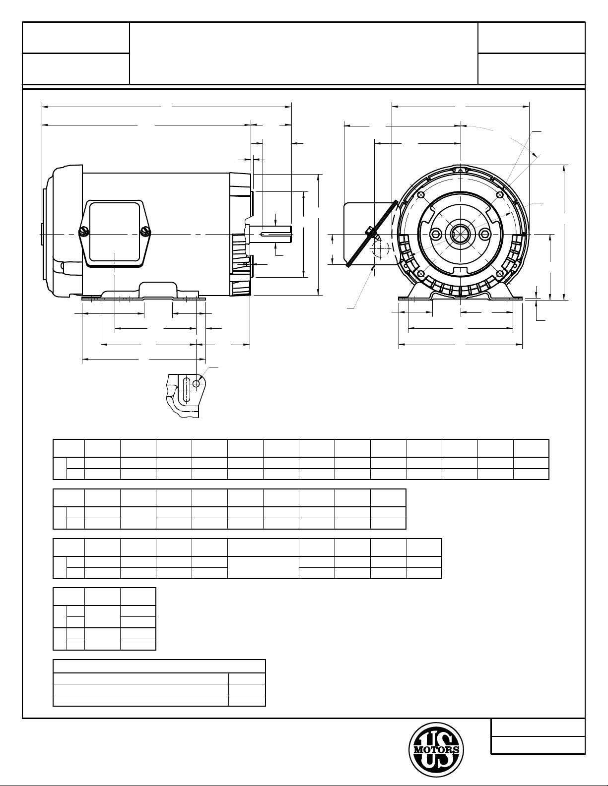
HORIZONTAL MOTORS
TEFC
FRAME: 143, 145TC
BASIC TYPE: UT
PRINT:
07-3109
SHEET:
1 OF 1
K2
AG
2F
B
BS
C
AH
ES
AB
AC
P
45°
BF
4 HOLES
BB
AJ
K
BA
EV
BC
U
BD
AK
AA SIZE
CONDUIT
AF
J
E
2E
A
O
D
G
H
4 HOLES
ALL DIMENSIONS ARE IN INCHES AND MILLIMETERS
BF
3,4
2E
±.03
5.50
140
AG
11.00
279
G
.13
2.13
54
4.28
109
UNITS
6.50
IN
165
MM
IN
IN
IN
IN
U
-.0005
.8750
22.225
BA
2.75
70
FRAME
143TC
145TC
UNITS
MM
UNITS BS
MM
UNITS
MM
MM
B
6.50
165
AA
.75
BB
MIN
.13
3
2F
±.03
4.00
102
5.00
127
C
13.13
334
5
AB
6.13
156
BC
.13
3
D
-.06
3.50
89
AC
4.53
115
BD
MAX
6.50
165
E
2.75
70
AF AJAH
1.59
40
3/8-16 X .75
TOLERANCES
FACE RUNOUT .004 TIR
PERMISSIBLE ECCENTRICTY OF MOUNTING RABBET .004 TIR
PERMISSIBLE SHAFT RUNOUT .002 TIR
H
+.05
.34
3
9
5.875
149.23
ES
MIN
1.41
36
1. DIMENSIONS MAY VARY .25" DUE TO CASTING AND/OR
FABRICATION VARIATIONS
2. LARGEST MOTOR WIDTH
3. ALL TAP HOLES ARE UNIFIED NATIONAL COARSE, RIGHT
HAND THREAD
4. TAP SIZE AND BOLT PENETRATION ALLOWANCE
5. BASIC CONDUIT FITTING SIZE. HOLE OPENING ON THE SIDE
OF THE CONDUIT BOX (REPRESENTED BY A DASHED CI RCLE)
WILL ACCEPT A .50 BASIC CONDUIT FITTING
6. THE CONDUIT BOX MAY BE LOCATED ON EITHER SIDE OF
THE MOTOR. THE CONDUIT OPENING(S) MAY BE LOCATED
IN STEPS OF 180° REGARDLESS OF LOCATION. STANDARD
LOCATION IS SHOWN WITH THE CONDUIT OPENING DOWN
7. TOLERANCES ARE SHOWN IN INCHES ONLY
8. FRAME REFERENCE; 7.75/143/145
J
1.75
44
AK
-.003
4.500
114.30
EV
.50
13
K
1.75
44
SQ KEY
.188
4.78
K2
3.25
83
OA
7.16
182
P
7.31
186
2
07-3109/-
Nidec Motor Corporation
St. Louis, Missouri
INFORMATION DISCLOSED ON THIS DOCUMENT
IS CONSIDERED PROPRIETARY AND SHALL NOT BE
REPRODUCED OR DISCLOSED WITHOUT WRITTEN
CONSENT OF NIDEC MOTOR CORPORATION
ISSUED BY
R. TIMMERMANN
APPROVED BY
M. CULLEN
IHP_DP_NMCA (MAR-2011) SOLIDEDGE
Page 4
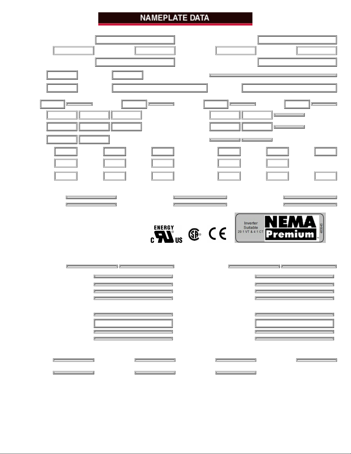
CATALOG NUMBER: U2P2DC NAMEPLATE PART #: 422702-002
MODEL FD15 FR 145TC TYPE UTE ENCL TEFC
SHAFT
END BRG
6205-2Z-J/C3 - QTY 1
OPP
END BRG
6203-2Z-J/C3 - QTY 1
PH 3
MAX
AMB
40 C
ID#
INSUL
CLASS
F
Asm.
Pos.
F1 DUTY CONT
HP 2 RPM 1750
VOLTS 460 230 208
FL
AMPS
2.9 5.7 5.9
SF
AMPS
3.4 6.7
SF 1.25 DESIGN B CODE M
NEMA NOM
EFFICIENCY
86.5
NOM
PF
76.7 KiloWatt 1.5
GUARANTEED
EFFICIENCY
84.0
MAX
KVAR
1.2 HZ 60
HP 2 RPM 1430
VOLTS 380 190
FL
AMPS
3.3 6.7
SF
AMPS
SF 1.00 DESIGN B CODE J
NEMA NOM
EFFICIENCY
82.5
NOM
PF
82.5
GUARANTEED
EFFICIENCY
80.0
MAX
KVAR
1 HZ 50
HAZARDOUS LOCATION DATA (IF APPLICABLE):
DIVISION CLASS I GROUP I
TEMP CODE CLASS II GROUP II
VFD DATA (IF APPLICABLE):
VOLTS AMPS
TORQUE 1 TORQUE 2
VFD LOAD TYPE 1 VFD LOAD TYPE 2
VFD HERTZ RANGE 1 VFD HERTZ RANGE 2
VFD SPEED RANGE 1 VFD SPEED RANGE 2
SERVICE FACTOR FL SLIP
NO. POLES 4 MAGNETIZING AMPS 1.7
VECTOR MAX RPM Encoder PPR
Radians / Seconds Encoder Volts
TEAO DATA (IF APPLICABLE):
HP (AIR OVER)
HP (AIR OVER
M/S)
RPM (AIR
OVER)
RPM (AIR OVER
M/S)
FPM AIR
VELOCITY
FPM AIR
VELOCITY M/S
FPM AIR
VELOCITY SEC
Page 5

ADDITIONAL NAMEPLATE DATA:
Decal / Plate WD=344136 Customer PN
Notes Non Rev Ratchet
Max Temp Rise 80C RISE/RES@1.00SF OPP/Upper Oil Cap GREASE
Thermal (WDG) SHAFT/Lower Oil Cap GREASE
Altitude Usable At
Regulatory Notes Regulatory Compliance CC 030A
COS Marine Duty
Balance Arctic Duty
3/4 Load Eff. 86.4 Inrush Limit
Motor Weight (LBS) 35 Direction of Rotation
Sound Level Special Note 1
Vertical Thrust (LBS) Special Note 2
Thrust Percentage Special Note 3
Bearing Life Special Note 4
Starting Method Special Note 5
Number of Starts Special Note 6
200/208V 60Hz Max Amps 7.3 SH Max. Temp.
190V 50 hz Max Amps 6.7 SH Voltage
380V 50 Hz Max Amps 3.3 SH Watts
NEMA Inertia Load Inertia
Sumpheater Voltage Sumpheater Wattage
Special Accessory Note 1 Special Accessory Note 16
Special Accessory Note 2 Special Accessory Note 17
Special Accessory Note 3 Special Accessory Note 18
Special Accessory Note 4 Special Accessory Note 19
Special Accessory Note 5 Special Accessory Note 20
Special Accessory Note 6 Special Accessory Note 21
Special Accessory Note 7 Special Accessory Note 22
Special Accessory Note 8 Special Accessory Note 23
Special Accessory Note 9 Special Accessory Note 24
Special Accessory Note 10 Special Accessory Note 25
Special Accessory Note 11 Special Accessory Note 26
Special Accessory Note 12 Special Accessory Note 27
Special Accessory Note 13 Special Accessory Note 28
Special Accessory Note 14 Special Accessory Note 29
Special Accessory Note 15 Special Accessory Note 30
Heater in C/B Voltage Heater in C/B Watts
Zone 2 Group Division 2 Service Factor
Note 1 Note 2
Note 3 Note 4
Note 5 Note 6
Note 7 Note 8
Note 9 Note 10
Note 11 Note 12
Note 13 Note 14
Note 15 Note 16
Note 17 Note 18
Note 19 Note 20
Note 21 Note 22
NIDEC MOTOR CORPORATION
ST. LOUIS, MO
TYPICAL NAMEPLATE DATA
ACTUAL MOTOR NAMEPLATE LAYOUT MAY VARY
SOME FIELDS MAY BE OMITTED
Nidec trademarks followed by the ® symbol are registered with the U.S. Patent and Trademark Office.
Page 6

MODEL NO. CATALOG NO. PHASE TYPE FRAME
FD15 U2P2DC 3 UTE 145TC
ORDER NO. 23176 LINE NO.
MPI: 143290 143291 143292 143293 143294
HP: 2 2 2 2 2
POLES: 4 4 4 4 4
VOLTS: 460 230 208 380 190
HZ: 60 60 60 50 50
SERVICE FACTOR: 1.15 1.15 1 1 1
EFFICIENCY (%):
S.F. 85.9 85.9
FULL 85.5 85.5 85.5 83.5 83.5
3/4 86.4 86.4 86.6 85.4 85.4
1/2 84.2 84.2 85.4 85 85
1/4 75.9 75.9 78.6 78.5 78.5
POWER FACTOR (%):
S.F. 80.1 80.1
FULL 76.7 76.7 81.8 82.5 82.5
3/4 68.3 68.3 75 75.3 75.3
1/2 54.8 54.8 62.7 62.4 62.4
1/4 34.7 34.7 41.1 39.8 39.8
NO LOAD 7.5 7.5 8 7.5 7.5
LOCKED ROTOR 66.6 66.6 65.2 71.6 71.6
AMPS:
S.F. 3.1 6.3
FULL 2.9 5.7 5.9 3.3 6.7
3/4 2.4 4.8 4.8 2.6 5.3
1/2 2 4.1 3.9 2.1 4.3
1/4 1.8 3.6 3.2 1.8 3.6
NO LOAD 1.7 3.5 3 1.7 3.4
LOCKED ROTOR 25.3 51 45 22.6 45
NEMA CODE LETTER M M K J J
NEMA DESIGN LETTER B B B B B
FULL LOAD RPM 1750 1750 1735 1430 1430
NEMA NOMINAL / EFFICIENCY (%) 86.5 85.5 85.5 83.5 83.5
GUARANTEED EFFICIENCY (%) 84 82.5 82.5 80 80
MAX KVAR 1.2 1.2 0.9 1 1
AMBIENT (°C) 40 40 40 40 40
ALTITUDE (FASL) 3300 3300 3300 3300 3300
SAFE STALL TIME-HOT (SEC) 10 10 13 12 12
SOUND PRESSURE (DBA @ 1M) 54 54 54 50 50
TORQUES:
BREAKDOWN{% F.L.} 478 478 382 356 356
LOCKED ROTOR{% F.L.} 368 368 289 290 290
FULL LOAD{LB-FT} 6 6 6.1 7.4 7.4
NEMA Nominal and Guaranteed Efficiencies are up to 3,300 feet above sea level and 25 ° C ambient
The Above Data Is Typical, Sinewave Power Unless Noted Otherwise
NIDEC MOTOR CORPORATION
ST. LOUIS, MO
Nidec trademarks followed by the ® symbol are registered with the U.S. Patent and Trademark Office.
Page 7

Motor Wiring Diagram
9 Lead, Dual Voltage (WYE Conn.)
T1
T4
T7
B109144
T9
T6
T3
T8
T5
T2
Y - Connection
Hi - VoltsLo - Volts
6
789
1 1223
Line
3
Line
45645
789
B109144
To reverse direction of rotation interchange connections L1 and L2.
In such case each cable will be marked with the appropriate lead number.
Connection Plate: B109144
Connection Decal: 344136
Each lead may have one or more cables comprising that lead.
Page 8

FRAMES - 56 THRU B145
UNIMOUNT TOTALLY ENCLOSED MOTORS
TYPES: FUT, FUTF, FUTF4, UT, UT1, UT4, UTE, UTE1, UTE4, UTEF, UTEN, , UTEF1, UTEF4, UTF, UTF1, UTF4, UTFI,
UTFI4, UTFN, UTI, UTN, UTNI, UTQ, UTV, UTVE
THIS PARTS LIST IS GOOD FOR THE FOLLOWING TYPES:
Types Frames
UT, FUT
56, 56C
143T, TC, TD, TCZ
145T, TC, TD, TCZ
B145T, TC, TD
UT-1 143, 145, B145JP
UT-4
143, 145, B145JM
Types Frames
UTE, UTQ 143, 145, B145T
UTF
56C,
143TC, TD
145TC, TD
UTN 143, 145T
UTV 143, 145TCV, JMV, JPV
UTFN 56C
WARNING:
Any disassembly or repair work on explosionproof motors
will void the Underwriters Laboratories, Inc. label unless
done by the manufacturer, or a facility approved by the
Underwriters Laboratories, Inc. Refer to your nearest
sales office for assistance.
BEARINGS:
Refer to motor nameplate for the
bearing numbers.
PRICES:
Parts stocking distributors: refer to
renewal parts numerical index. All
Others: refer to your nearest parts
distributor.
reference: Renewal Parts Section 700, Pages 12 & 13
Page 9

FRAMES - 56 THRU B145
UNIMOUNT TOTALLY ENCLOSED MOTORS
TYPES: FUT, FUTF, FUTF4, UT, UT1, UT4, UTE, UTE1, UTE4, UTEF, UTEN, , UTEF1, UTEF4, UTF, UTF1, UTF4, UTFI,
UTFI4, UTFN, UTI, UTN, UTNI, UTQ, UTV, UTVE
ITEM
NO. QTY NAME OF PART
1 1 Fan Cover (not used on types UTN & UTFN)
2 3
Self Tapping Screw & Lockwasher (not used on types UTN
& UTFN)
3 1
Fan (fan assembly on types UTE, 3600 RPM and UTQ) (not
used on types UTN & UTFN)
4 1
Retaining Snap Ring (not used on UTE, 3600 RPM and
UTN, UTQ and UTFN)
5 1 Bracket
6 4 Round Head Machine Screw
7 4 Bushing
8 4 Plastic Plug
9 1 Bracket Plug (used on types UTN & UTFN only)
10 1 Spring Wave Washer (not on type UTV)
11 1 Ball Bearing
12 1 Rotor Assembly (includes item 12 & 13)
13 1 Rotor Core
14 1 Shaft
15-19 - Not Used
20 1 Wound Stator Assembly (includes items 21 and 22 if used)
21 1 Mounting Base (not used on types UTF, UTV, UTFN)
22 6
Hex Head Cap Screw (not used on types UTF, UTV, and
UTFN)
23 1 Gasket
24 1 Outlet Box Base
25 2 Self Tapping Screw
26 1 Gasket
27 1 Outlet Box Cover
28 2 Self Tapping Screw
29-34 - Not Used
35 1 Ball Bearing
36 1
Retaining Snap Ring (not used on frames 56 and 56C, also
types UTN and UTQ)
37 1 Bracket
ITEM
NO. QTY NAME OF PART
38 4 Hex Nut
39 1 Square Key
40-49 - Not Used
For Types UT, UTF, UTV and UTFN with "C" bracket, and types UT-1 and
UT-4 omit items 37, 38 and item 10 on frames 143, 145, and B145
50 1 "C" Bracket
51 1 Clamping Plate (not used on frame 56C)
52 2
Hex Head Cap Screw (not used on frames 143, 145, &
B145)
53 2 Not Used
For types UT and UTF with "D" bracket, omit items 10, 37, and 38, and add
the following parts
60 1 "D" Bracket
61 1 Bearing Cap
62 2 Hex Head Cap Screw
63-69 - Not Used
For type UTV and units with canopy cap, add the following parts
70 1 Canopy Cap
71 1 Spacer
72 1 Hex Head Cap Screw and Lockwasher
73 1 Square Nut
74-79 - Not Used
For SHUR-STOP bakes, omit items 1, 3 and 4, and refer to section 770 for
part addition
For Dings and Stearns brake, omit items 1, 2, and 5, and add the following
80 1
Brake (for replacement parts for brake, refer to the brake
manufacturer)
81 2 Socket Head Cap Screw
82 1 Key
83 1 Bracket Mounting Bracket
84 3 Round Head Machine Screw abd Lockwasher
85 1 Bracket
WARNING:
Any disassembly or repair work on explosionproof motors
will void the Underwriters Laboratories, Inc. label unless
done by the manufacturer, or a facility approved by the
Underwriters Laboratories, Inc. Refer to your nearest
sales office for assistance.
BEARINGS:
Refer to motor nameplate for the
bearing numbers.
PRICES:
Parts stocking distributors: refer to
renewal parts numerical index. All
Others: refer to your nearest parts
distributor.
reference: Renewal Parts Section 700, Pages 12 & 13
Copyright © 2010 Nidec Motor Corporation. All rights reserved.
Page 10

General Information for Integral Horsepower (IHP) Motors
on Variable Frequency Drives (VFDs)
Variable Frequency Drives (VFD)
A VFD is a type of controller used to vary the speed of an electric motor.
The VFD takes a xed AC voltage and frequency and allows it to be
adjusted in order to get different speeds from the motor. Motor speed
can be varied by changing the frequency of the input power waveform.
The equation below shows how the frequency affects the speed of a
three phase induction motor.
• VFD dv/dt - winding end turn differential in voltage
versus differential in time
• High temperatures or high humidity
• Grouding system
Wider speed ranges, higher voltages, higher switching frequencies,
insufcient grounding and increased cable lengths all add to the severity
of the application and, therefore, the potential for premature motor
failure.
120* Fundamental Input Frequency
Speed =
Number of Motor Poles
How does a VFD work?
A VFD takes the xed frequency and voltage sine wave from the power
grid or power station and puts it through a few steps in order to allow
the VFD user to vary the frequency and in turn control the motor speed.
First it recties the AC power into DC Power. Because of this step, a
term commonly used instead of VFD is inverter. This only describes one
step of what the VFD does to the power waveform. Once rectied into
a DC voltage the drive sends the power through a set of transistors or
switches. These switches can take the DC waveform and by opening
and closing at certain speeds and durations can create an output
waveform that mimics the sine wave that is required to drive a three
phase electric motor. The output wave form is known as a Pulse Width
Modulation (PWM) waveform because the waveform is created by
multiple pulses of the switches at short intervals.
PULSE WIDTH MODULATION WAVEFORM
Line
to
Neutral
Voltage
Line
Current
Figure 1 PWM Waveform
What variables should be considered when
deciding whether to power a motor with a VFD?
VFD compatibility with motors is complex. As a result, many variables
must be considered when determining the suitability of a particular motor
for use with a VFD. These variables include:
• Torque requirements (Constant or Variable)
• Speed Range
• Line / System Voltage
• Cable length between the VFD and the motor
• Drive switching (carrier) frequency
• Motor construction
*This information applies only to Integral Horsepower (IHP) motors as dened on the Agency Approval page, under UL®† & CSA®† listings where indicated.
How does a VFD affect the motor?
There are many things to consider when a motor is powered using a
VFD or PWM power. When a motor is powered by a PWM waveform
the motor windings very often see a large differential voltage, either from
phase to phase or turn to turn. When the voltage differential becomes
large enough it creates a reaction at the molecular level that converts
available oxygen into O3. This phenomenon is called partial discharge or
corona. This reaction creates energy in the form of light and heat. This
energy has a corrosive effect on the varnish used to protect the motor
windings. PWM waveforms can also magnify shaft voltages which lead
to arcing across the bearing and causing premature bearing failure.
Corrective action must be taken to mitigate these issues that arise when
using an electric motor with a VFD.
How do I protect the motor?
Nidec Motor Corporation (NMC) has developed specic motor designs
to decrease the harmful affects that a VFD can have on a motor.
NMC’s INVERTER GRADE® insulation system is the rst line of
defense against corona and phase to phase faults that can be common
when a motor is powered using a PWM waveform. The INVERTER
GRADE® insulation system is standard on all of NMC’s Inverter Duty
products. Along with the INVERTER GRADE
are installed as a minimum protection against over heating the motor.
Special consideration must also be given to bearings in motors powered
by VFD’s. In order to create a low resistance path to ground for built
up shaft voltages a shaft grounding device can be used. On larger
horsepower motors an insulated bearing system should be used in
conjunction with the shaft grounding device when installed, to force the
stray shaft voltages to ground. The bearing failures are more prominent
on motors with thrust handling bearings. NMC has created an Inverter
Duty vertical motor line that not only uses the INVERTER GRADE
insulation system, but that also comes standard with a shaft grounding
device. On motors that are 100 HP and greater the thrust bearing is also
insulated for additional protection.
®
insulation, thermostats
®
What does "Inverter Duty" mean?
An Inverter Duty motor should describe a motor that helps mitigate
potential failure modes of a motor that is powered by a VFD. Inverter
duty motor windings should be able to withstand the voltage spikes per
NEMA MG1 Part 31.4.4.2 and protect against overheating when the
motor is run at slow speeds. On thrust handling bearings it is apparent
that the bearings require additional protection. Inverter Duty vertical
motors should have a shaft grounding device to protect the motor
bearings from uting due to voltage discharge through the bearing. On
larger motors (100HP and larger) the shaft should also be electrically
isolated from the frame in order to aid the shaft grounding ring in
discharging the shaft voltages to ground.
vii www.usmotors.com
Page 11

Motor / Inverter
Compatibility
Thermal Overloads and Single Phase Motors
Motors with thermal overloads installed may not operate properly on a VFD. The current
carrying thermal overload is designed for sine wave power. Operation on a VFD may cause
nuisance tripping or potentially not protect the motor as would be expected on line power.
Thermostats or thermistors installed in the motor and connected properly to the VFD may
provide suitable thermal overload protection when operating on a VFD.
(consult codes for installation requirements)
Single phase motors and other fractional horsepower ratings are not designed to be
operated on a VFD. Within Nidec Motor Corporation standard products, all motors NEMA
48 frame (5.5” diameter) and smaller are not suitable for VFD applications. Three phase
56 and 143/145 frame applications should be noted on the catalog price page; or if in
doubt ask a Nidec Motor Corporation technical representative for recommendations on
compatibility with a VFD.
Slow Speed Motors
Motors with a base design of slower than six poles require special consideration regarding
VFD sizing and minimizing harmonic distortion created at the motor terminals due to
cable installation characteristics. Additional external PWM waveform lters and shielded
motor cables designed for PWM power may be required to provide acceptable motor life.
Harmonic distortion on the output waveform should be kept to a minimum level (less than
10%) mismatch impedance.
690V Applications
Motors that are rated for 690VAC and that will be powered by 690VAC PWM VFDs require
the use of an external lter to limit peak voltage spikes and the use of an INVERTER
GRADE® motor. Where available, an alternative to using an output lter is to upgrade to a
2300V insulation system.
Low Voltage TITAN® Motors
When using 449 frame and larger motors on PWM type VFDs consider the use of an
external lter and shielded motor cables designed for PWM power to minimize harmonic
distortion and peak voltages at the motor terminals. Harmonic distortion on the output
waveform should be kept to a minimum level (less than 10%).
Bearing Currents Related to PWM Waveforms
Protection of the motor bearings from shaft currents caused by common mode voltages
is becoming a standard feature on Inverter Duty motor products. Some installations may
be prone to a voltage discharge condition through the motor bearings called Electrical
Discharge Machining (EDM) or uting. Vertical HOLLOSHAFT and HOSTILE DUTY World
Motor come with grounding devices installed as standard. EDM damage is related to
characteristics of the PWM waveform, and the VFD programming, and installations factors.
Bearing Protection on Inverter Duty Vertical Motors
All U.S. MOTORS® brand “Inverter Duty” vertical products have a shaft grounding system
that allows damaging shaft currents a low resistance path to ground. Bearings on vertical
motors fed by VFD power without this bearing protection are not covered under any
warranty. All other bearing failure is covered per NMC’s standard warranty. An electric
motor repair shop approved to service U.S. MOTORS® brand motors must verify that the
cause of the bearing failure was not due to EDM damage.
Guideline For Insulated Anti-Friction Bearings
Bearing insulation is required to prevent circulating shaft currents which can damage
bearings. Circulating shaft current can be caused by use of improper power and/or
ground cables, improper grounding systems and higher switching frequencies. Finding
and correcting the external condition(s) is the responsibility of the system designer
or specifying engineer. To prevent circulating shaft current in motors with anti-friction
bearings, Nidec Motor Corporation’s standard practice is to insulate the non-drive end
bearing.
Adjustable Speed Drives produce a common mode voltage condition. To interrupt common
mode voltage on induction motors of all sizes, NEMA MG1-2018 Part 31 recommends
insulating both bearings. In cases where both anti-friction bearings are insulated, the
system designer or specifying engineer should determine whether to apply one or more
of the following options to prevent or reduce shaft currents: sinewave lters, line reactors
or mechanical devices, such as shaft grounding or an insulated half coupling. Motors
with shaft grounding devices are not suitable for installation in hazardous locations unless
housed in an enclosure suitable for the specied Division (or Zone), Class and Group(s).
Multiple Motors on a Single VFD
Special considerations are required when multiple motors are powered from a single
VFD unit. Most VFD manufacturers can provide guidelines for proper motor thermal
considerations and starting/stopping of motors. Cable runs from the VFD and each motor
can create conditions that will cause extra stress on the motor winding. Filters may be
required at the motor to provide maximum motor life.
Grounding and Cable Installation Guidelines
®†
Proper output winding and grounding practices can be instrumental in minimizing motor
related failures caused by PWM waveform characteristics and installation factors. VFD
manufacturers typically provide detailed guidelines on the proper grounding of the motor
to the VFD and output cable routing. Cabling manufacturers provide recommended cable
types for PWM installations and critical information concerning output wiring impedance
and capacitance to ground.
Integrated Motor and Inverter
By integrating the motor and inverter at NMC’s manufacturing facility, many of the motor
compatibility problems are minimized or eliminated. During the manufacturing process, the
motor is matched to the inverter characteristics which ensures the winding temperature
and torque levels meet the design specication. Since the inverter output wiring to the
motor is nearly eliminated, bearing currents are rarely experienced. When the unit is
properly grounded, reducing the output cable lengths in conjunction with an inverter grade
insulation system and low factory setting of the switching frequency of the inverter drive,
results in low risk of voltage peaks produced by the PWM waveform.
Vertical Motors on VFDs
Vertical motors operated on VFD power present unique conditions that may require
consideration by the user or installation engineer:
• Locked rotor and drive tripping caused by non-reversing-ratchet operation at
low motor speeds. It is not recommended to operate motors at less than 1/4 of
synchronous speed. If slow speeds are required contact NMC engineering.
• Unexpected / unacceptable system vibration and or noise levels caused by the
torque pulsation characteristics of the PWM waveform, a system critical frequency
falling inside the variable speed range of the process or the added harmonic content
of the PWM waveform exciting a system component
• Application related problems related to the controlled acceleration/deceleration and
torque of the motor on VFD power and the building of system pressure/ load.
• The impact the reduction of pump speed has on the down thrust reected to the
pump motor and any minimum thrust requirements of the motor bearings
• Water hammer during shutdown damaging the non-reversing ratchet
Humidity and Non-operational Conditions
The possible build-up of condensation inside the motor due to storage in an uncontrolled
environment or non-operational periods in an installation, can lead to an increased rate of
premature winding or bearing failures when combined with the stresses associated with
PWM waveform characteristics. Moisture and condensation in and on the motor winding
over time can provide tracking paths to ground, lower the resistance of the motor winding
to ground, and lower the Corona Inception Voltage (CIV) level of the winding.
Proper storage and maintenance guidelines are important to minimize the potential of
premature failures. Space heaters or trickle voltage heating methods are the common
methods for drying out a winding that has low resistance readings. Damage caused by
these factors are not covered by the limited warranty provided for the motor unless
appropriate heating methods are properly utilized during non-operational periods
and prior to motor start-up.
NEMA®† Application Guide for AC Adjustable Speed Drive Systems: http://www.
nema.org/stds/acadjustable.cfm#download
* This information applies only to Integral Horsepower (IHP) motors as dened on the Agency Approval page, under UL®† & CSA®† listings where indicated.
www.usmotors.com viii
Page 12

Warranty Guidelines for Integral Horsepower
(IHP)* Motors on Variable Frequency Drives
Warranty Guidelines
The information in the following section refers to the motor and drive
application guidelines and limitations for warranty.
• On TITAN® frame motors, inquiry required for suitability on constant
torque loads.
Cable distances are for reference only and can be further limited by
hot and humid environments (refer to Table 1). Refer to specic VFD
Hazardous Location Motors
Use of a variable frequency drive with the motors in this catalog, intended
for use in hazardous locations, is only approved for Division1, Class I,
Group D hazardous location motors with a T2B temperature code, with
a limitation of 2:1 constant torque or 10:1 variable torque output. No
Switching Frequency 460 Volt 230 Volt 380 Volt
other stock hazardous location motors are inherently suitable for
operation with a variable frequency drive. If other requirements are
needed, including non-listed Division 2, please contact your Nidec Motor
Corporation territory manager to conduct an engineering inquiry.
575 Volt Motors
575 volt motors can be applied on Inverters when output lters are
used. Contact the drive manufacturer for lter selection and installation
requirements.
Applying INVERTER GRADE® Insulated Motors on
manufacturers cable limits. Refer to the Motor/ Inverter Compatibility page
for special consideration of vertical motor bearings.
Variable Frequency Drives (2, 4, 6 pole)
The products within this catalog labeled “Inverter Duty” or “Vector Duty”
are considered INVERTER GRADE
®
GRADE
motors exceed the NEMA®† MG-1 Part 31 standard.
Nidec Motor Corporation provides a three-year limited warranty on all
®†
NEMA
frame INVERTER GRADE® insulated motors and allows long
®
insulated motors. INVERTER
cable runs between the motor and the VFD (limited to 400 feet without
Warranty Period Clarications and Exceptions
Standard Energy Efcient Exclusion
Applying Standard & Energy Efcient Motors on Variable Frequency Drives
is not recommended. VFD related failures on standard and energy efcient
motors will not be covered under warranty.
output lters). Cable distance can be further limited by hot and humid
environments and VFD manufacturers cable limits. These motors may be
appropriate for certain severe inverter applications or when the factors
relating to the end use application are undened (such as spares).
Vertical Motor Windings
Premium efcient vertical motors without INVERTER GRADE
that are installed using the criteria described in this document and applied in
the correct applications shall have a warranty while powered by a VFD for
Nidec Motor Corporation’s U.S. Motors
INVERTER GRADE
®
insulated motors:
®
brand is available in the following
• Inverter Duty NEMA®† frame motors good for 20:1 Variable Torque
& 5:1 Constant Torque, including Vertical Type RUSI (10:1 V.T.)
• Inverter Duty motors rated for 20:1 Constant Torque
• ACCU-Torq® and Vector Duty Motors with full torque to 0 Speed or
5000:1
• 841 Plus® NEMA®† Frame Motors
12 months from date of installation or 18 months from date of manufacturing
whichever comes rst. See limited warranty page for horizontal motor
warranty periods.
Bearing Exclusion for Thrust Handling Bearings
Bearings used in premium efcienct vertical motors, and all thrust handling
bearings, that are powered by VFDs without shaft grounding devices or
insulated bearings (when required) will not be covered under any warranty
for damages caused from being powered by a VFD. All other bearing failure
is covered per NMC’s standard warranty. An electric motor repair shop
approved to service U.S. MOTORS
of the bearing failure was not due to Electrical Discharge Machining.
Table 1 - Cable Distances
Maximum Cable Distance VFD to Motor
3 Khz 127 ft 400 ft 218 ft
6 Khz 90 ft 307 ft 154 ft
9 Khz 73 ft 251 ft 126 ft
12 Khz 64 ft 217 ft 109 ft
15 Khz 57 ft 194 ft 98 ft
20 Khz 49 ft 168 ft 85 ft
®
insulation
®
brand motors must verify that the cause
Applying Premium Efcient motors (that do not have INVERTER
®
GRADE
Premium efcient motors without INVERTER GRADE insulation meet
minimum NEMA
insulation) on Variable Frequency Drives (2, 4, 6 pole)
®†
MG-1, Section IV, Part 31.4.4.2. These motors can be
used with Variable Frequency Drives (with a reduced warranty period)
under the following parameters:
• On NEMA®† frame 447 and smaller motors, 20:1 speed rating on
variable torque loads & 4:1 speed range on constant torque loads.
• On TITAN® 449 and larger frame motors, 10:1 speed rating on
variable torque loads.
* This information applies only to Integral Horsepower (IHP) motors as dened on the Agency Approval page, under UL®† & CSA
Medium Voltage and Slow Speed Considerations
Motors that are rated above 700 VAC or that are eight pole and slower
require special consideration and installation and are not covered under the
warranty guidelines in this document. Motors that are rated above 700VAC
have special cable length and voltage differential issues that are specic
to the VFD type and manufacture. The motor construction and cost may
vary dramatically depending on the VFD topology and construction. Contact
your NMC representative with VFD manufacturer name and model type for
application and motor construction considerations. Motors that are designed
eight pole and slower also require special installation and lters per the drive
manufacturer.
ix
®†
listings where indicated.
 Loading...