

Page 1
STOCK# 91824
OPERATOR’S MANUAL
!
WARNING
To reduce the risk of injury, the user
must read and understand the
Operator’s Manual before using this
product.
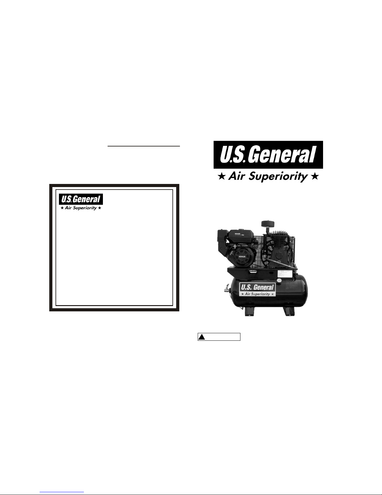
30 GALLON
AIR COMPRESSOR
REV0905
12.75 HP KOHLER
GAS ENGINE
MODEL: US1230G
Warranty Statement
LIMITED
WARRANTY
Harbor Freight Tools Co. makes every effort to assure that its products meet high
quality and durability standards, and warrants to the original purchaser that this
product is free from defects in materials and workmanship for a period of two years
from date of purchase.
(90 days if used by a professional contractor or if used as rental equipment).
This warranty does not apply to damage due directly or indirectly to misuse, abuse,
negligence or accidents; repairs or alterations outside our facilities; or lack of
maintenance. We shall in no event be liable for death, injuries to persons or
property, or for incidental, contingent, special or consequential damages arising
from the use of our product.
Some states do not allow the exclusion or limitation of incidental or consequential
damages, so the above limitation of exclusion may not apply to you. To take
advantage of this warranty, the product or part must be returned to us with
transportation charges prepaid. Proof of purchase date and an explanation of the
complaint must accompany the merchandise. If our inspection verifies the defect,
we will either repair or replace the product at our election or we may elect to refund
the purchase price if we cannot readily and quickly provide you with a replacement.
We will return the repaired products at our expense, but if we determine there is no
defect, or that the defect resulted from causes not within the scope of our warranty,
then you must bear the cost of returning the product. This warranty gives you
specific legal rights and you may also have other rights which vary from state to
state.
3491 Mission Oaks Blvd. PO Box 6009 Camarillo, CA 93011 (800)444-3353
Page 2
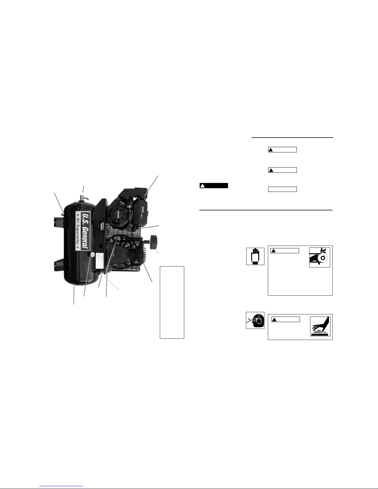
Parts List US1230G
September 2005
Pump
B6000
Engine
ECS12ST
Safety Valve (200 psi)
SV25200
Beltguard
BG31184R
Pressure Gauge
GA300
Tan k
TK30GB
Drive Pulley S2AK74H
Belt(2) BA69
Idle Control IC34
Beltguard Fastener 5001369
Unloader/Pilot Valve
Tank Drain
U109
Ball Valve
BV75
FIB02DC16
Discharge Tube
DT027
Filter Assem.
FS002
2Page 1
Safety Instructions
This manual contains information that is
very important to know and understand.
This information is provided for SAFETY
and to PREVENT EQUIPMENT PROBLEMS. To help recognize this information, observe the following symbols.
Safety Signal Words
Danger indicates
an imminently hazardous situation which, if not avoided,
WILL result in death or serious injury.
Warning indicates
a potentially hazardous situation which, if not avoided,
COULD result in death or serious injury.
Caution indicates a
potentially hazardous situation which, if not avoided,
MAY result in minor or moderate injury.
Notice indicates
important information, that if not followed, may cause damage to equipment.
!
NOTICE
!
CAUTION
!
WARNING
!
DANGER
Since the air compressor and other components (pump, spray guns, filters, lubricators, hoses, etc.) used make up a high
pressure pumping system, the following
safety precautions must be observed at
all times:
1. Read all manuals included with this product carefully. Be thoroughly familiar with the controls and
the proper use of the
equipment.
2. Follow all local safety codes as well
as the United States Occupational
Safety and Health Act (OSHA)
3. Only persons well acquainted with
these rules of safe operation should
be allowed to use the compressor.
4. Keep visitors away and NEVER allow
children in the work area.
5. Wear safety glasses and
use hearing protection
when operating the pump
or unit.
6. Do not stand on or use the pump or
unit as a handhold.
7. Before each use, inspect compressed
air system, fuel system and electrical
components for signs of damage,
deterioration, weakness or leakage.
Repair or replace defective items
before using.
8. Check all fasteners at frequent intervals for proper tightness.
9. Do not wear loose clothing or jewelry
that will get caught in the moving
parts of the unit.
Before Using the Air Compressor
MANUAL
Never operate
compressor without
a beltguard. Compressors can start automatically without warning. Personal
injury or property damage
could occurfrom contact with
moving parts.
!
WARNING
Compressor parts
may be hot even if
the unit is stopped.
!
CAUTION
Page 1
Page 3
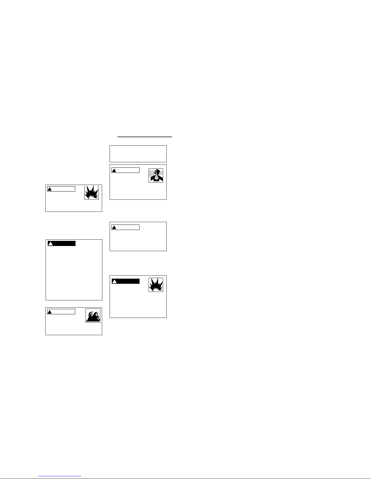
10. Keep fingers away from a running
compressor; fast moving and hot
parts will cause injury and/or burns.
11. If the equipment should start to
vibrate abnormally, STOP the
engine/motor and check immediately
for the cause. Vibration is generally a
warning of trouble.
!
WARNING
NEVER refuel a running or hot engine.
Explosive fuel can cause fires and
severe burns. Avoid overfilling fuel
tank.
12. Check fuel level before starting the
engine. Do not fill the gas tank
indoors. Wipe off any spilled gas
before starting the engine.
!
DANGER
Gasoline vapor is highly flammable. Refill outdoors or only in well
ventilated areas. Do not store,
spill or use gasoline near an open
flame or heat devices such as a
stove, furnace, or water heater,
which utilize a pilot light, or any
device that can create a spark. If
gasoline is accidentally spilled,
move unit away from the spill area
and avoid creating any source of
ignition until gasoline vapors have
dissipated.
!
WARNING
Motors, electrical equipment and controls can
cause electrical arcs that will
ignite a flammable gas or vapor.
Never operate or repair in or near
a flammable gas or vapor. Never
store flammable liquids or gases
in the vicinity of the compressor.
!
WARNING
Carbon monoxide can
cause severe nausea,
fainting or death. Do
not operate unit
inside a closed building or a poorly ventilated area.
13. To reduce fire hazard, keep
engine/motor exterior free of oil, sol vent, or excessive grease.
!
WARNING
Never remove or attempt to adjust
safety valve. Keep safety valve
free from paint and other accumulations.
14. Do not tamper with governor setting
on engine. Overspeeding the unit
severely shortens engine life and may
also be very hazardous.
!
DANGER
Never attempt to repair
or modify tank!
Welding, drilling or any
other modifications will weaken the
tank resulting in damage from rupture or explosion. Always replace
worn or damaged tanks.
15. Tanks rust from moisture build-up,
which weakens the tank. Make sure to
drain tank daily and inspect periodical ly for unsafe conditions such as rust
formation and corrosion.
Safety Instructions (continued)
Page 2
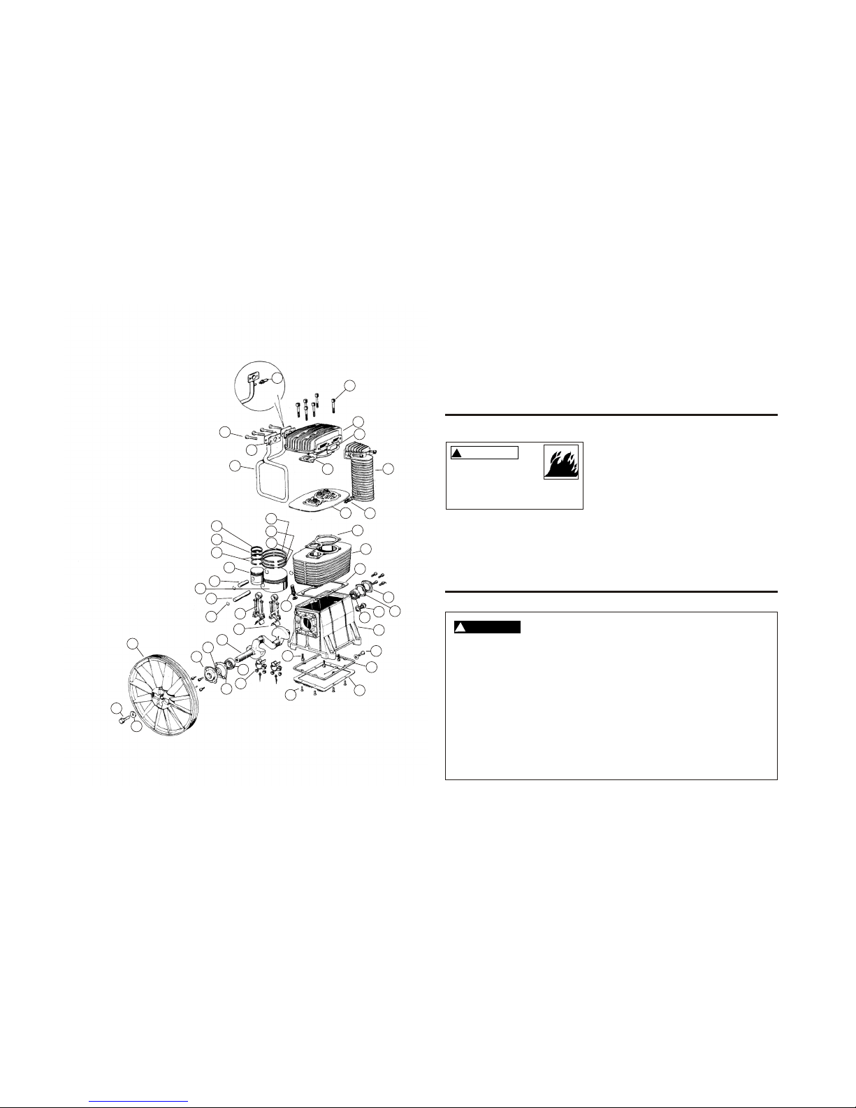
1. Crankcase 6061100
2. Cylinder 6030000
3. Head 6061401
4. Crankshaft 6061200
5. Crankcase Bottom 6061301
6. Crankcase Bottom Gasket 6050101
7. Valve Plate 6040051
8. Conrod Bearing (2 per Rod) 9013014
9. Connecting Rod 6011101
10. Conrod Nut 9128234
11. HP Piston 6021100
12. LP Piston 6022100
13. HP Wrist Pin 6021200
14. LP Wrist Pin 6022200
15. Circlip 9140060
16. HP Ring 9020011
17. HP Ring 9020041
18. HP Ring 9020073
19. LP Ring 9020016
20. LP Ring 9020046
21. LP Ring 9020076
22. Aftercooler 5070100
23. Bearing Housing (NDS) 5061690
24. Bearing Housing (DS) 6061590
25. Intercooler 5262010
26. Flywheel 5000100
27. Main Bearing 9170020
28. Main Bearing 9170090
29. Oil Sight Glass 9022003
30. Oil Fill Plug 9024006
31. Oil Seal 9163030
32. Flywheel Bolt 9110024
33 Flywheel Washer 9004009
34. Aftercooler Safety Valve Sv25225
35. Intercooler Safety Valve 9049064
36. Head Bolt 9101754
37. Cooler Bolt 9101254
38. Cylinder Bolt 9101324
39. Crankcase Btm. Bolt 9114262
40. Head Gasket 6050400
41. Cylinder Gasket 6050300
42. Aftercooler Gasket 5070200
43. Intercooler Gasket 5050600
44. Bearing Housing Gasket DS 6050500
45. Bearing Housing Gasket NDS 5050500
46. Frame Gasket 6050200
47. Oil Drain Tube 9053201
Gasket Kit 6050057
Filter Assembly FS002
Filter Element FE001
Page 11
Page 4
4
2
8
3
9
5
6
20
7
1
19
18
17
16
15
14
13
11
12
10
34
33
32
31
30
29
28
27
26
25
24
23
22
21
35
37
36
40
42
43
41
45
44
46
38
39
47
Page 10
B6000
16. Fast moving air will stir up dust and
debris which may be harmful.
Release air slowly when draining
moisture or depressurizing the com pressor system.
17. STOP the engine whenever leaving the
work area, before cleaning, making
repairs or inspections. When cleaning,
!
DANGER
This Compressor/pump is not equipped and should not be used “as is” to supply
breathing quality air. For any application of air for human consumption, the air
compressor/pump will need to be fitted with suitable in-line safety and alarm equipment. This additional equipment is necessary to properly filter and purify the air to
meet minimal specifications for Grade D breathing as described in Compressed Gas
Association Commodity Specification G 7.1 - 1966, OSHA 29 CFR 1910. 134, and/or
Canadian Standards Associations (CSA).
DISCLAIMER OF WARRANTIES
In the event the compressor is used for the purpose of breathing air application and
proper in-line safety and alarm equipment is not simultaneously used, existing
warranties shall be voided, and The Manufacturer disclaims any liability whatsoever
for any loss, personal injury or damage.
!
WARNING
Do not spray flammable materials in vicinity of open flame or
near ignition sources including the
compressor unit.
repairing or inspecting, make certain all
moving parts have stopped. Disconnect
the spark plug wire and keep the wire
away from the plug to prevent acciden tal starting.
18. Allow engine to cool before storing.
Spraying Precautions
19. Do not smoke when spraying paint,
insecticides, or other flammable sub stances.
20. Use a face mask/respirator when
spraying and spray in a well ventilat-
ed area to prevent health and fire
hazards.
21. Do not direct paint or other sprayed
material at the compressor. Locate
compressor as far away from the
spraying area as possible to mini mize overspray accumulation on the
compressor.
22. When spraying or cleaning with sol vents or toxic chemicals, follow the
instructions provided by the chemi cal manufacturer.
Breathable Air Warning
Page 3
Page 5
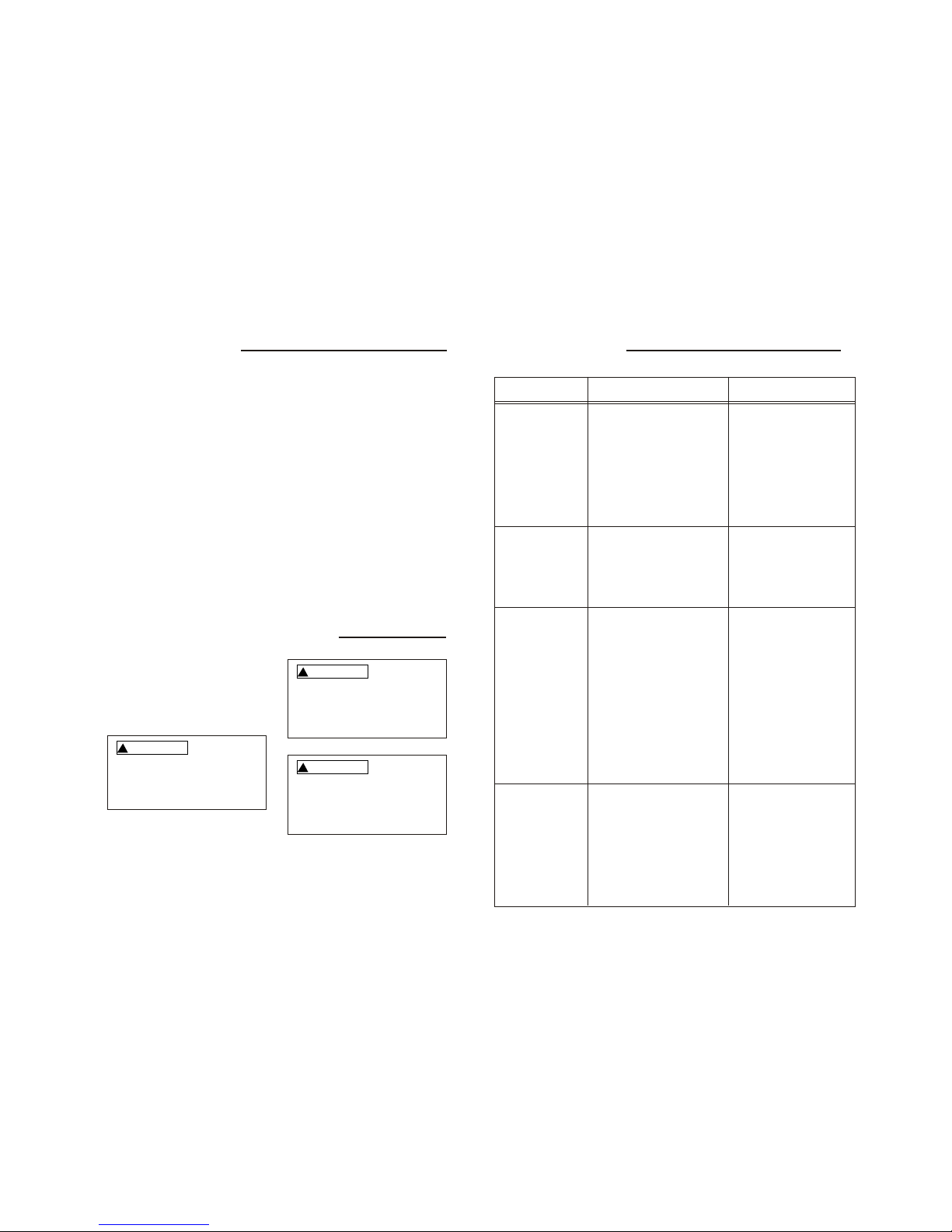
ASME Safety Valve
A safety valve that automatically releases
the air if the air receiver (tank) pressure
exceeds the preset maximum.
PSI (Pounds per Square Inch)
Measurement of the pressure exerted by
the force of the air. The actual psi output
is measured by a pressure gauge on the
compressor.
ACFM (Actual Cubic Feet per Minute)
Sometimes called CFM (Cubic Feet per
Minute). Measurement of air volume
delivered by the compressor at a given
pressure..
Air Delivery
A combination of psi and SCFM. The air
delivery required by a tool is stated as
(number) SCFM at (Number) psi. The
combination of these figures determines
what size compressor is needed.
!
WARNING
Glossary of Terms
Regulator (Not Included)
A control that adjusts the line pressure to
the proper amount needed to operate
spray guns and air tools.
Tank Pressure Gauge
Indicates tank pressure in psi.
Unpacking and Checking Contents
1. Remove the air compressor from the
carton.
2. Place the compressor on a secure,
stationary work surface and look it
over carefully.
Do not operate unit if damaged
during shipping, handling or use.
Damage may result in bursting
and cause injury or property damage.
!
WARNING
To reduce the risk of injury, if any
parts are missing, do not attempt to
assemble the air compressor until
the missing parts are obtained and
installed correctly.
!
WARNING
For your own safety, never operate
unit until all assembly steps are
complete and until you have read
and understood the entire operator’s
manual.
Page 4
Troubleshooting
TROUBLE REMEDYPROBABLE CAUSE
Overheating 1. Relocate the compressor
to an area where an ample
supply of cool, clean, dry
and well-circulated air is
available
2. Clean the cooling surfaces
of pump and engine.
3. Check air requirements of
tools
1. Poor ventilation
2. Dirty cooling surfaces
3. Compressor undersized for
application
1. Increase idle, refer to
engine manual for details
2. Check for proper oil level
3. Replace
1. Low engine idle
2. Improper lubrication
3. Defective pilot/unloader valve
Unit stalls
Excessive noise
1. Loose pulleys are a com mon cause of “knocking”.
Tighten appropriate bolts
2. Check for proper oil level
3. Replace
4. Remove piston assembly
and replace necessary
parts
5. Replace bearings and oil
6. Check for proper belt
tension
1. Loose drive pulley or flywheel
2. Lack of oil in crankcase
3. Worn connecting rod
4. Worn wrist pin bushing
5. Worn bearings
6. Loose belts
Oil in the discharge
air
1. Change oil. Check oil
recommendations on page
7 of this manual
2. See above section
3. Clean or replace air filter
4. Replace
1. Wrong type or inferior grade
of oil
2. Overheating
3. Restricted intake air
4. Worn piston rings
Page 9
Page 6
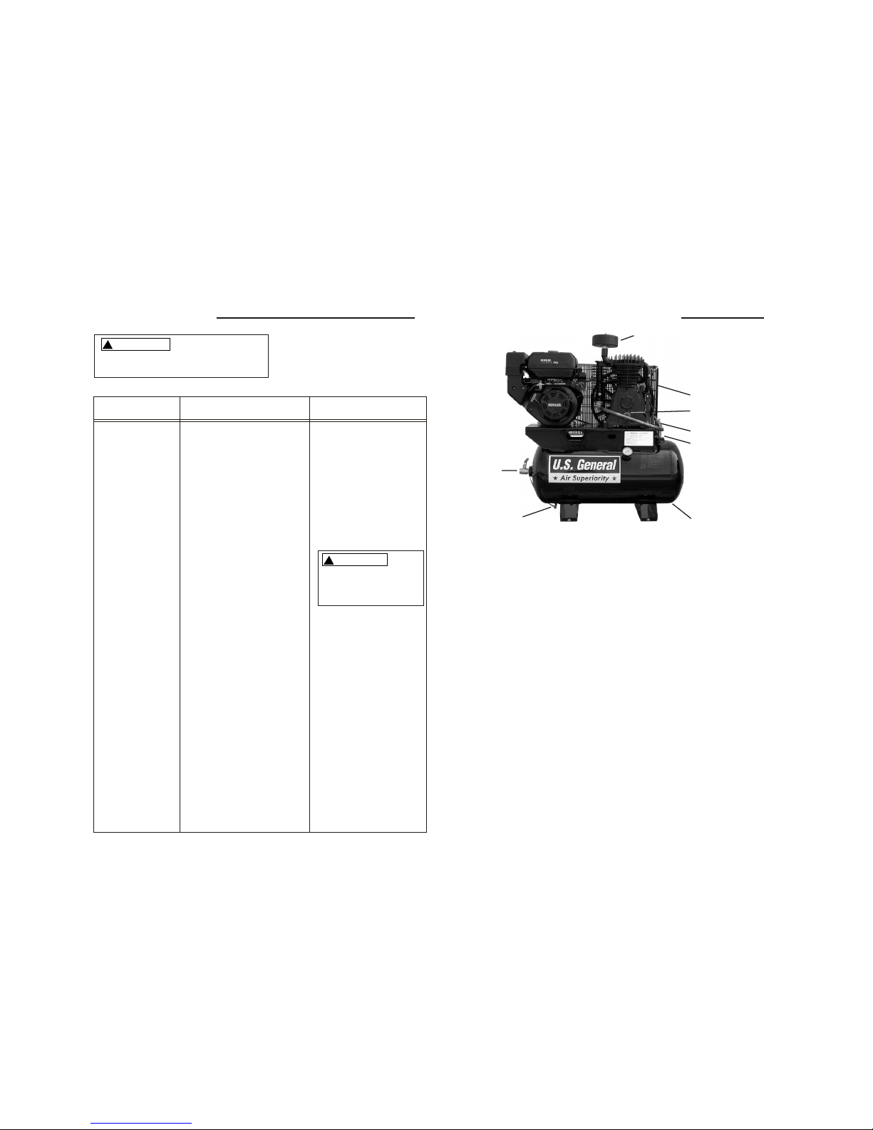
Getting to Know Your Air Compressor
Belt Guard
Pilot/Unloader Vave
Air Filter
Safety Valve
Air Storage Tank
Tank Drain
Ball Valve
Oil Sight Glass
1. Belt Guard. The belt guard encloses the
pulleys and drive belt. It protects the
user from moving parts and directs
cooling air to the compressor pump.
2. Air Filter. The air filter keeps dirt and
debris from entering the compressor
pump and reduces compressor noise.
3. Oil Sight Glass. The oil sight glass
shows proper level and cleanliness of
the oil. Oil level should show ½ full
4. Tank Drain Valve. The tank drain valve
allows moisture to be removed from the
tank.
5. Pilot/Unloader Valve. The pilot/unloader
valve controls the engine rpm. When
loaded, the engine will run at maximum
operating speed and air will enter the
tank. When compressor reaches maximum
pressure, the engine will slow to an idle
and air will vent to atmosphere.
6. ASME Safety Valve. This valve auto-
matically releases air if the tank pressure
exceeds the preset maximum.
7. Ball Valve. The ball valve allows unregulated
outlet air with pressure up to 175 psi.
8. Air Storage Tank. The tank stores air for
later use.
9. Regulator and Gauge (Not Included).
Outlet air can be regulated by adjusting
the regulator knob. Clockwise will raise
outlet pressure and counterclockwise will
lower outlet pressure. Outlet pressure will
be displayed on gauge.
10. Tank Pressure Gauge. The tank pressure
gauge will display air pressure in tank.
Page 5
Troubleshooting
!
WARNING
For your own safety do not try and
run the air compressor while troubleshooting.
TROUBLE REMEDYPROBABLE CAUSE
Low discharge pressure
1. Listen for escaping air.
Ally soap solution to all
fittings and connections.
Bubbles will appear at
points of leakage. Tighten
or replace leaking fittings
or connections
2. Remove head and inspect
for valve breakage, weak
valves, scored valve plate,
etc. Replace defective
parts and reassemble
1. Air leaks
2. Leaking valves
!
CAUTION
Be sure that the old head
gasket is replaced with a
new one each time the
head is removed
3. Clean or replace air filter
element.
4. Replace and gaskets
proven faulty on inspection
5. Loosen engine mounting
bolts and move engine in
a direction away from the
compressor, being sure
that the engine pulley is
perfectly aligned with the
flywheel. Tighten engine
mounting bolts. Proper
belt tension should not
allow more than about ½
travel with less that 5
pounds of force
3. Restricted air intake
4. Blown gaskets
5. Slipping belts
Page 8
Page 7
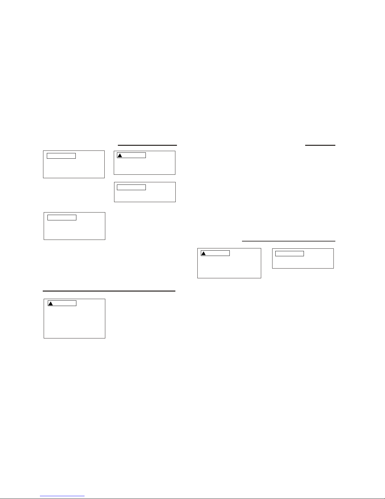
Operating Your Compressor
!
CAUTION
All lubricated compressor pumps discharge some condensed water and oil
with the compressed air. Install appropriate water/oil removal equipment and controls as necessary for the intended application.
NOTICE
Before starting the compressor,
thoroughly read all component
instruction manuals, especially the
engine manual.
NOTICE
Failure to install appropriate
water/oil removal equipment may
result in damage to machinery or
workpiece.
NOTICE
Do not attach air tools to open
end of the hose until start-up is
completed and unit checks OK.
To ensure proper operation, unit
must be on a level surface.
Moisture in compressed air will form into
droplets as it comes from an air compressor pump. When humidity is high or when
a compressor is in continuous use for an
extended period of time, this moisture will
collect in the tank. When using a paint
spray gun, this water will be carried from
the tank through the hose, and out of the
gun as droplets mixed with the spray
material.
Moisture in Compressed Air
IMPORTANT: This condensation will cause
water spots in a paint job, especially when
spraying other than water based paints.
A filter in the air line, located as near to the
gun as possible will eliminate most of this
moisture..
Start-Up
3. Connect the negative (-) battery cable
to a mounting bolt or an acceptable
engine ground connection.
4. Connect the positive (+) battery cable
to the positive (+) battery terminal.
5. Connect the negative (-) battery cable
to the negative (-) battery terminal.
IMPORTANT: Number 2 wire or larger
is recommended.
1. Locate the starter solenoid terminal.
This is the top post farthest from the
block with the small red wire..
2. Connect the positive (+) battery cable
to the starter solenoid terminal.
Battery Connection
!
CAUTION
Make sure to follow instructions
carefully to avoid a short and possible damage to the starter solenoid
and/or battery. Always connect the
positive (+) battery cable to the
starter solenoid before connecting
the negative (-) battery cable.
1. Turn the gas lever to the “On” position.
Turn the choke lever to the left.
Turn key to the “On” position, then to
the “Start” position or pull start grip to
start the engine. Once the engine is
running, turn the choke lever to the
original “right hand” position.
See Engine Manual for More Detailed Instructions
Page 6
2. This compressor is equipped with an auto matic start- relief valve. This valve allows
the unit to run (unloaded) for a few
seconds before air pressure starts to build
in the tank.
3. When maximum tank pressure is reached,
the compressor automatically unloads,
slowing the engine to idle. The engine
remains at idle until tank pressure falls
to a preset level. The engine will then
accelerate and air will once again build
pressure in the tank.
4. To turn off compressor, turn key to the
“Off” position.
Note: Turn Gas Off when not in use.
Remember to drain moisture from tank
daily.
Operating Your Compressor (continued)
Adjusting A Regulator
(Regulator must be purchased Separately)
1. To adjust the regulator, pull out on the
regulator knob. Turn regulator knob
clockwise to raise outlet pressure and
turn regulator knob counterclockwise to
decrease outlet air pressure.
2. Once desired outlet pressure is obtained,
push regulator knob in to lock setting.
Maintenance
!
WARNING
Disconnect spark plug and drain
air system completely of all air
pressure prior to performing
maintenance on compressor..
NOTICE
Consult engine manual for scheduled
maintenance instructions.
DAILY
1. Check oil level at sight glass. Check
engine oil level.
2. Drain moisture from tank.
3. Visually check for loose parts or
excessive noise or vibration.
WEEKLY
1. Inspect air filter. Replace if necessary.
2. Check safety valve by pulling ring and
releasing. Valve should seal once
released.
3. Clean excessive dirt/dust from unit..
MONTHLY
Check belt tension and alignment.
3 Months
Change Oil. A compressor grade nondetergent oil should be used.
Most automotive detergent oils cause excess
carbon build-up and should not be used.
Cold climates (Below 30°F) use 20WT
Moderate Climates (30°F-90°F) use 30WT
Hot Climates (Above 90°F) use 40WT
Page 7
Page 8

Table of Contents
Section Page
Safety Instructions
1
Safety Signal Words
Before Using the Air
Compressor
Spraying Precautions
Breathable Air Warning
Glossary of Terms 4
Unpacking and Checking
Content 4
Getting to Know Your Air
Compressor 5
Operating Your Air Compressor 6
Moisture in Compressed Air
Lubricaton
Start-up
To Start Gasoline Engine
Section Page
Maintenance
7
Maintenance Schedule
Adjusting the Regulator
Filter Removal, Inspection, and
Replacement
Drive Belt
Troubleshooting 8-9
Replacement Parts
10-12
Notes
13
1
1
3
3
6
7
6
6
7
7
7
7
Warranty Statement
14
Notes
Page 9
4
2
8
3
9
5
6
20
7
1
19
18
17
16
15
14
13
11
12
10
34
33
32
31
30
29
28
27
26
25
24
23
22
21
35
37
36
B6000
40
42
43
41
45
44
46
38
39
47
Page 10

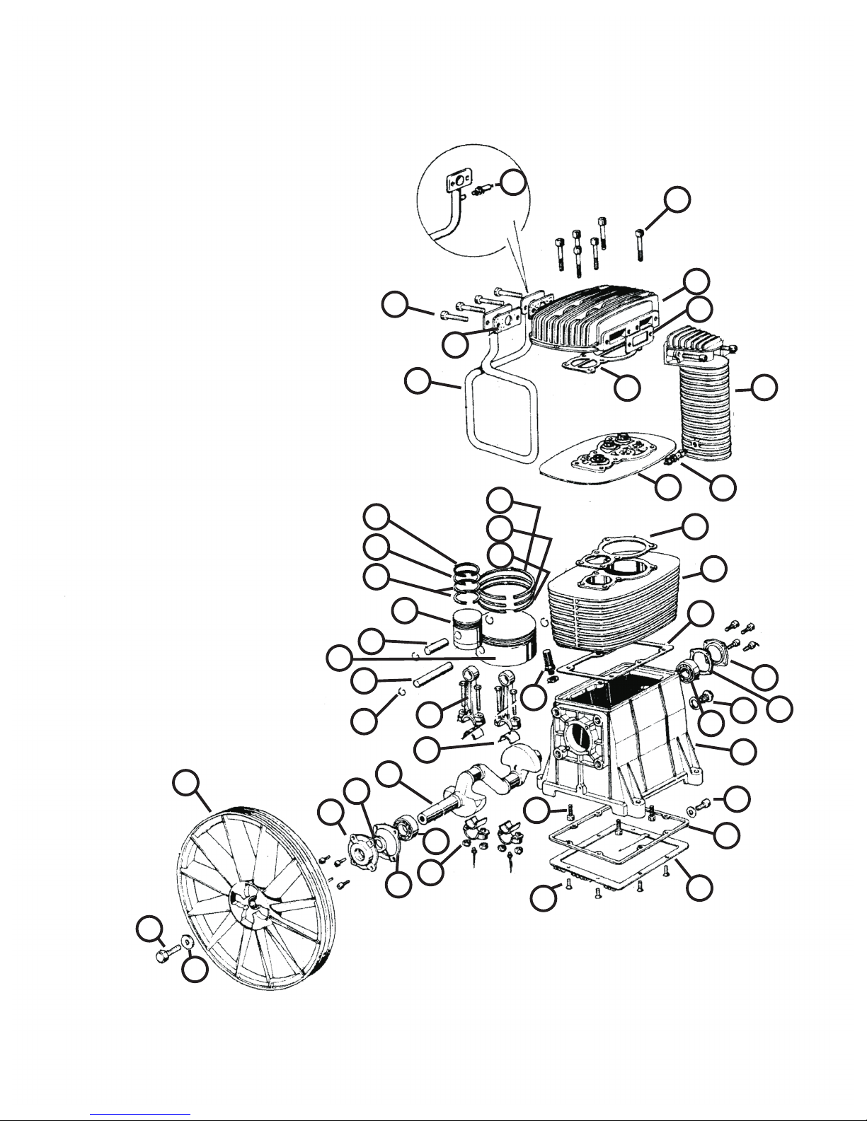
B6000
1. Crankcase 6061100
2. Cylinder 6030000
3. Head 6061401
4. Crankshaft 6061200
5. Crankcase Bottom 6061301
6. Crankcase Bottom Gasket 6050101
7. Valve Plate 6040051
8. Conrod Bearing (2 per Rod) 9013014
9. Connecting Rod 6011101
10. Conrod Nut 9128234
11. HP Piston 6021100
12. LP Piston 6022100
13. HP Wrist Pin 6021200
14. LP Wrist Pin 6022200
15. Circlip 9140060
16. HP Ring 9020011
17. HP Ring 9020041
18. HP Ring 9020073
19. LP Ring 9020016
20. LP Ring 9020046
21. LP Ring 9020076
22. Aftercooler 5070100
23. Bearing Housing (NDS) 5061690
24. Bearing Housing (DS) 6061590
25. Intercooler 5262010
26. Flywheel 5000100
27. Main Bearing 9170020
28. Main Bearing 9170090
29. Oil Sight Glass 9022003
30. Oil Fill Plug 9024006
31. Oil Seal 9163030
32. Flywheel Bolt 9110024
33 Flywheel Washer 9004009
34. Aftercooler Safety Valve SV25225
35. Intercooler Safety Valve 9049064
36. Head Bolt 9101754
37. Cooler Bolt 9101254
38. Cylinder Bolt 9101324
39. Crankcase Btm. Bolt 9114262
40. Head Gasket 6050400
41. Cylinder Gasket 6050300
42. Aftercooler Gasket 5070200
43. Intercooler Gasket 5050600
44. Bearing Housing Gasket DS 6050500
45. Bearing Housing Gasket NDS 5050500
46. Frame Gasket 6050200
47. Oil Drain Tube 9053201
Gasket Kit 6050057
Filter Assembly 6281007 or FS002
Filter Element 7081106 or FE001
Page 11
OWNER'S MANUAL
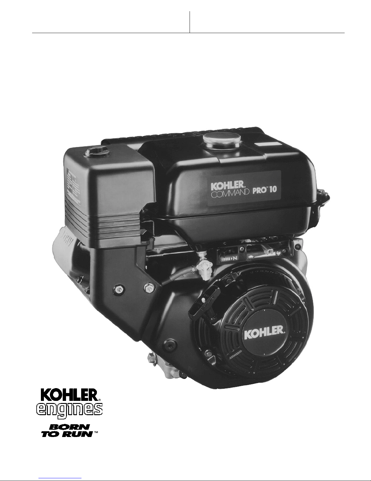
COMMAND PRO CS SERIES 4-12 HP
HORIZONTAL CRANKSHAFT
Page 12
Safety Precautions
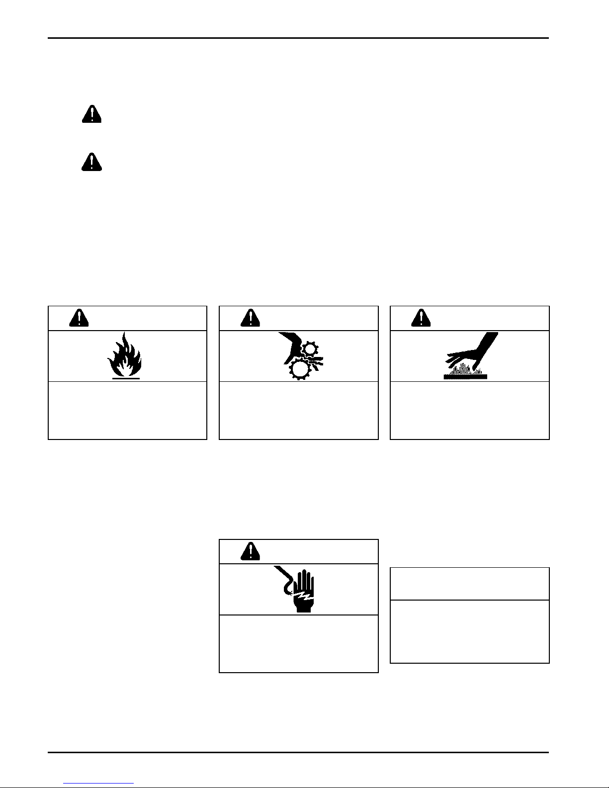
To insure safe operations please read the following statements and understand their meaning.
Also refer to your equipment owner's manual for other important safety information. This manual
contains safety precautions which are explained below. Please read carefully.
WARNING
Warning is used to indicate the presence of a hazard that can cause severe personal injury,
death, or substantial property damage if the warning is ignored.
CAUTION
Caution is used to indicate the presence of a hazard that will or can cause minor personal injury
or property damage if the caution is ignored.
NOTE
Note is used to notify people of installation, operation, or maintenance information that is
important but not hazard-related.
For Your Safety!
These precautions should be followed at all times. Failure to follow these precautions could result in
injury to yourself and others.
WARNING
Explosive Fuel can cause fires and
severe burns.
Stop engine before filling fuel tank.
Explosive Fuel!
Gasoline is extremely flammable
and its vapors can explode if
ignited. Store gasoline only in
approved containers, in well
ventilated, unoccupied buildings,
away from sparks or flames. Do not
fill the fuel tank while the engine is
hot or running, since spilled fuel
could ignite if it comes in contact
with hot parts or sparks from
ignition. Do not start the engine near
spilled fuel. Never use gasoline as a
cleaning agent.
WARNING
Rotating Parts can cause severe
injury.
Stay away while engine is in
operation.
Rotating Parts!
Keep hands, feet, hair, and clothing
away from all moving parts to
prevent injury. Never operate the
engine with covers, shrouds, or
guards removed.
CAUTION
Electrical Shock can cause injury.
Do not touch wires while engine is
running.
WARNING
Hot Parts can cause severe burns.
Do not touch engine while operating
or just after stopping.
Hot Parts!
Engine components can get
extremely hot from operation. To
prevent severe burns, do not touch
these areas while the engine is
runningor immediately after it is
turned off. Never operate the engine
with heat shields or guards
removed.
California
Proposition 65 Warning
Engine exhaust from this product
contains chemicals known to the
State of California to cause cancer,
birth defects, or other reproductive
harm.
2
Electrical Shock!
Never touch electrical wires or
components while the engine is
running. They can be sources of
electrical shock.
Page 13
Safety Precautions (Cont.)
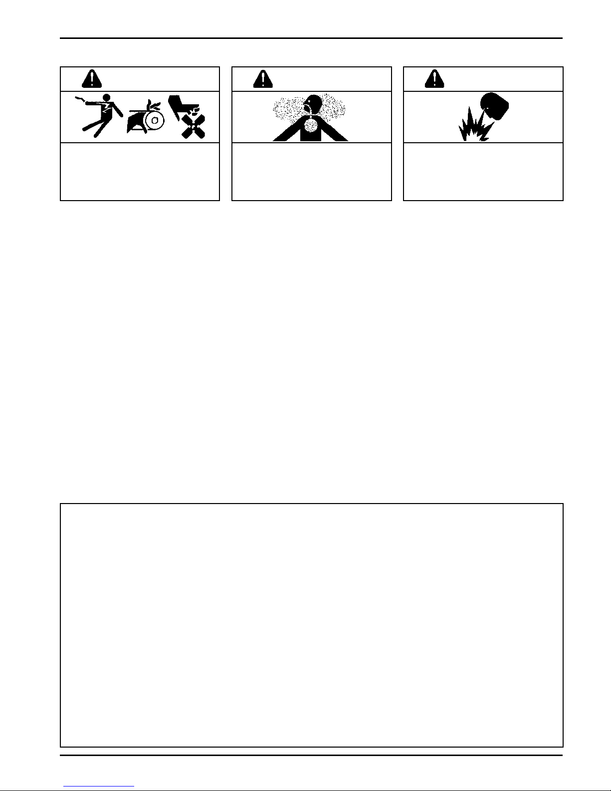
WARNING
Accidental Starts can cause severe
injury or death.
Disconnect and ground spark plug
lead before servicing.
Accidental Starts!
Disabling engine. Accidental
starting can cause severe injury
or death. Before working on the
engine or equipment, disable the
engine as follows: 1) Disconnect the
spark plug lead(s). 2) Disconnect
negative (-) battery cable from
battery.
WARNING
Carbon Monoxide can cause
severe nausea, fainting or death.
Do not operate engine in closed or
confined area.
Lethal Exhaust Gases!
Engine exhaust gases contain
poisonous carbon monoxide.
Carbon monoxide is odorless,
colorless, and can cause death if
inhaled. Avoid inhaling exhaust
fumes, and never run the engine in
a closed building or confined area.
WARNING
Explosive Gas can cause fires and
severe acid burns.
Charge battery only in a well
ventilated area. Keep sources of
ignition away.
Explosive Gas!
Batteries produce explosive
hydrogen gas while being charged.
To prevent a fire or explosion,
charge batteries only in well
ventilated areas. Keep sparks, open
flames, and other sources of ignition
away from the battery at all times.
Keep batteries out of the reach of
children. Remove all jewelry when
servicing batteries.
Before disconnecting the negative
() ground cable, make sure all
switches are OFF. If ON, a spark will
occur at the ground cable terminal
which could cause an explosion if
hydrogen gas or gasoline vapors
are present.
Congratulations You have selected a fine four-cycle, single cylinder, air-cooled engine. Kohler designs long
life strength and on-the-job durability into each enginemaking a Kohler engine dependabledependability you
can count on. Here are some reasons why:
Efficient overhead valve design and splash lubrication provide maximum power, torque, and reliability under
all operating conditions.
Dependable, maintenance free electronic ignition ensures fast, easy starts time after time.
Kohler engines are easy to service. All routine service areas (like the oil fill/check plug, air cleaner, spark plug,
and carburetor) are easily and quickly accessible.
Parts subject to the most wear and tear (like the cylinder liner, crankshaft, and camshaft) are made from
precision formulated cast iron. Because the cylinder liner can be rebored, these engines can last even longer.
Every Kohler engine is backed by a worldwide network of over 10,000 distributors and dealers. Service
support is just a phone call away. Call 1-800-544-2444 (U.S. & Canada) for Sales & Service assistance.
To keep your engine in top operating condition, follow the maintenance procedures in this manual.
3
Page 14
Air Cleaner
Cover Retaining
Knob
Fuel
Shut-Off
Choke Lever
Retractable Starter
Air Cleaner
Fuel Tank Cap
Fuel Tank
Throttle Lever
On/Off Switch
(some models)
Muffler
Oil Sentry
Light
Spark Plug
Valve Cover
Oil Fill/
Check Plug
Muffler Shield
Carburetor
Oil Drain
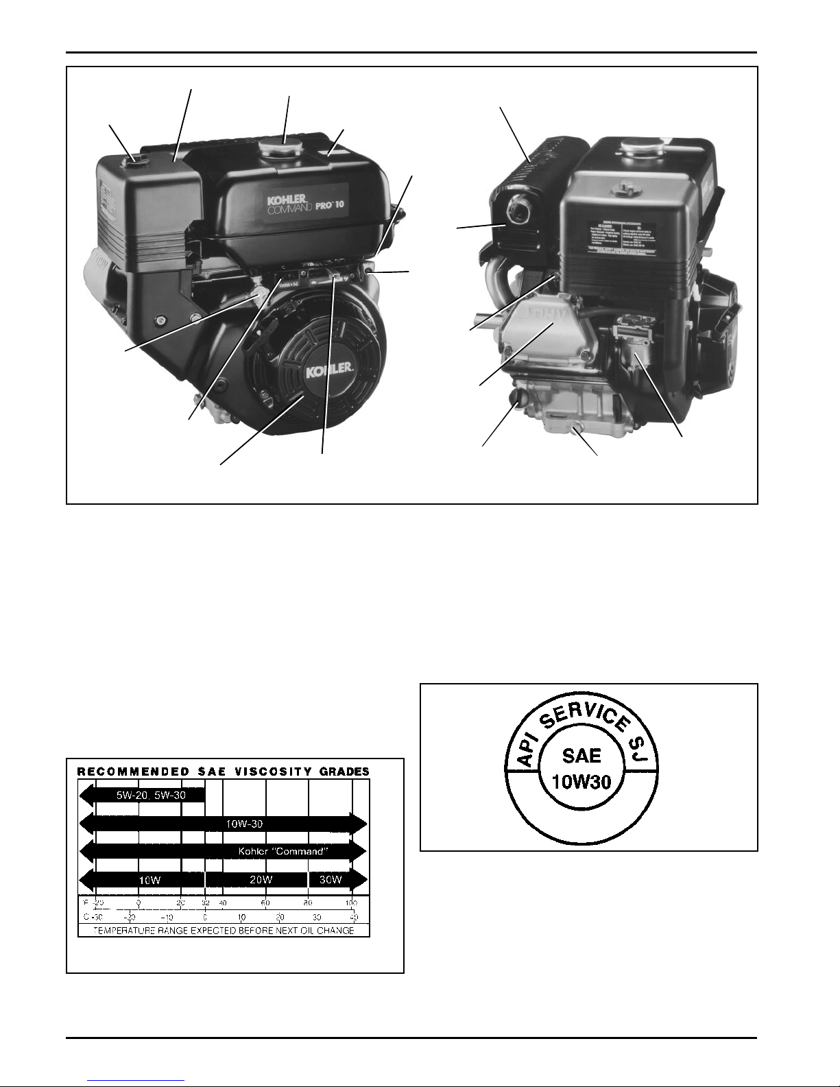
Figure 1. Location of Controls and Service Points on CS Engines.
Oil Recommendations
Using the proper type and weight of oil in the crankcase
is extremely important. So is checking oil daily and
changing oil regularly. Failure to use the correct oil, or
using dirty oil, causes premature engine wear and
failure.
Oil Type
Use high quality detergent oil of API (American
Petroleum Institute) service class SG, SH, SJ or
higher. Select the viscosity based on the air
temperature at the time of operation as shown in the
following table.
NOTE: Using other than service class SG, SH, SJ or
higher oil or extending oil change intervals
longer than recommended can cause engine
damage.
A logo or symbol on oil containers identifies the API
service class and SAE viscosity grade. See Figure 3.
Figure 3. Oil Container Logo.
Refer to Maintenance Instructions beginning on
page 8 for detailed oil check and oil change
procedures.
Synthetic oils should not be used.
Figure 2. Viscosity Grades Table.
4
Page 15
Fuel Recommendations
WARNING: Explosive Fuel!
Gasoline is extremely flammable and its vapors can
explode if ignited. Store gasoline only in approved
containers, in well ventilated, unoccupied buildings,
away from sparks or flames. Do not fill the fuel tank
while the engine is hot or running, since spilled fuel
could ignite if it comes in contact with hot parts or
sparks from ignition. Do not start the engine near spilled
fuel. Never use gasoline as a cleaning agent.
General Recommendations
Purchase gasoline in small quantities and store in
clean, approved containers. A container with a capacity
of 2 gallons or less with a pouring spout is
recommended. Such a container is easier to handle
and helps eliminate spillage during refueling.
Do not use gasoline left over from the previous season,
to minimize gum deposits in your fuel system and to
insure easy starting.
Do not add oil to the gasoline.
Engine Identification Numbers
When ordering parts, or in any communication involving
an engine, always give the Model, Specification, and
Serial Numbers of the engine.
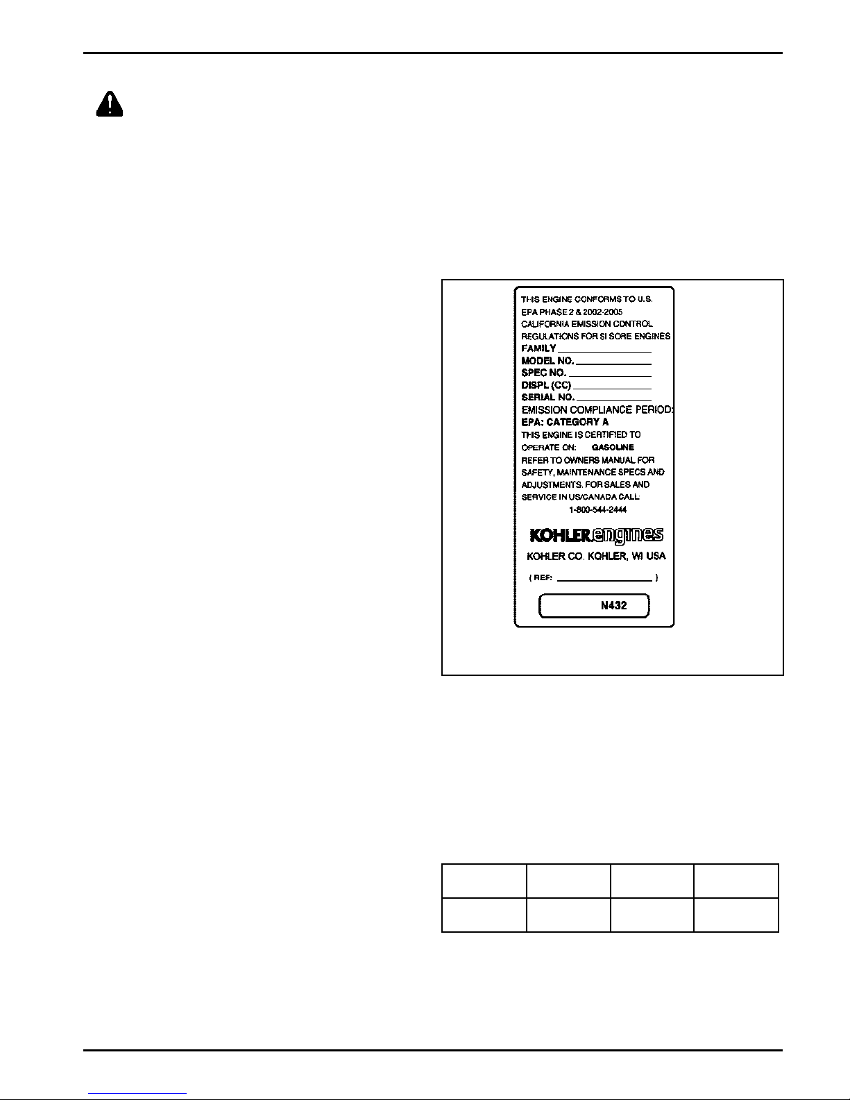
The engine identification numbers appear on a decal
(or decals) affixed to the engine shrouding. Include
letter suffixes, if there are any.
Record your engine identification numbers on the
identification label below (Figure 4) for future reference.
Do not overfill the fuel tank. Leave room for the fuel to
expand.
Fuel Type
For best results use only clean, fresh, unleaded
gasoline with a pump sticker octane rating of 87 or
higher. In countries using the Research method, it
should be 90 octane minimum.
Unleaded gasoline is recommended as it leaves less
combustion chamber deposits. Leaded gasoline may be
used in areas where unleaded is not available and
exhaust emissions are not regulated. Be aware
however, that the cylinder head will require more
frequent service.
Gasoline/Alcohol blends
Gasohol (up to 10% ethyl alcohol, 90% unleaded
gasoline by volume) is approved as a fuel for Kohler
engines. Other gasoline/alcohol blends are not
approved.
Gasoline/Ether blends
Methyl Tertiary Butyl Ether (MTBE) and unleaded
gasoline blends (up to a maximum of 15% MTBE by
volume) are approved as a fuel for Kohler engines.
Other gasoline/ether blends are not approved.
If your engine has this identification label, it is
certified to meet EPA/CARB standards.
Figure 4. Engine Identification Label.
The Emission Compliance Period referred to on the
Emission Control or Air Index label indicates the
number of operating hours for which the engine has
been shown to meet Federal and CARB emission
requirements. The following table provides the Engine
Complicance Period (in hours) associated with the
category descriptor found on the certification label.
Emission Compliance Period (Hours)
EPA
CARB
Refer to certification label for engine displacement.
Category C
250 Hours
Moderate
125 Hours
Category B
500 Hours
Intermediate
250 Hours
Category A
1000 Hours
Extended
500 Hours
Exhaust Emission Control System for models CS4-12
is EM.
5
Page 16
Operating Instructions
Also read the operating instructions of the equipment this engine powers.
Pre-Start Checklist
NOTE: This engine has been shipped without engine
oil. Fill with oil, otherwise it will not start.
Check oil level. Add oil if low. Do not overfill.
Check fuel level. Add fuel if low.
Check cooling air intake areas and external
surfaces of engine. Make sure they are clean and
unobstructed.
Check that the air cleaner components and all
shrouds, equipment covers, and guards are in
place and securely fastened.
Check that any clutches or transmissions are
disengaged or placed in neutral.
WARNING: Lethal Exhaust Gases!
Engine exhaust gases contain poisonous carbon
monoxide. Carbon monoxide is odorless, colorless,
and can cause death if inhaled. Avoid inhaling exhaust
fumes, and never run the engine in a closed building or
confined area.
Cold Weather Starting Hints
1. Be sure to use the proper oil for the temperature
expected. See Figure 2 on page 4.
2. Declutch all possible external loads.
3. Set speed control at part throttle position.
4. A warm battery has much more starting capacity
than a cold battery.
Starting
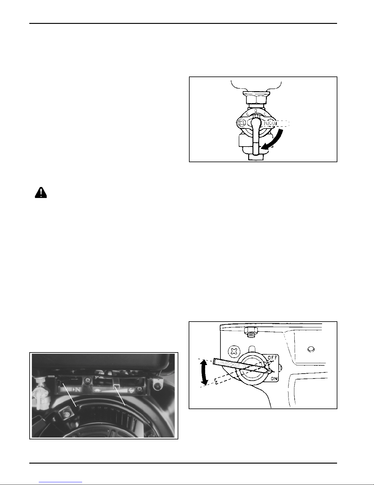
1. Turn fuel shut-off valve to on position. See
Figure 6.
Figure 6. On Position of Fuel Shut-Off Valve.
2. For a Cold Engine Place the throttle control
midway between the slow and fast positions.
See Figure 5. Place the choke control into the on
position.
For a Warm Engine (normal operating
temperatures) Place the throttle control midway
between the slow and fast positions. The
choke is not required to start a warm engine.
3. Start the engine as follows:
For Retractable Start Engine Turn engine
On/Off switch to on (see Figure 7) and SLOWLY
pull the starter handle until just past compression
STOP! Return starter handle, pull firmly with a
smooth, steady motion to start. Pull the handle
straight out to avoid excessive rope wear from the
starter rope guide.
5. Use fresh winter grade fuel. NOTE: Winter grade
gasoline has a higher volatility to improve starting.
Do not use gasoline left over from summer.
Choke
Control
Figure 5. Control Panel.
6
Throttle
Control
Figure 7. Retractable Start Engine On/Off Switch.
Extend the starting rope periodically and check its
condition. If the rope is frayed, have it replaced
immediately by your Kohler Engine Service Dealer.
Page 17
WARNING: Accidental Starts!
Disabling engine. Accidental starting can cause
severe injury or death. Before working on the engine
or equipment, disable the engine as follows: 1)
Disconnect the spark plug lead(s). 2) Disconnect
negative (-) battery cable from battery.
Stopping
1. If possible, remove the load.
2. Move the throttle control to the slow or low
idle position. Allow the engine to run at idle for
30-60 seconds.
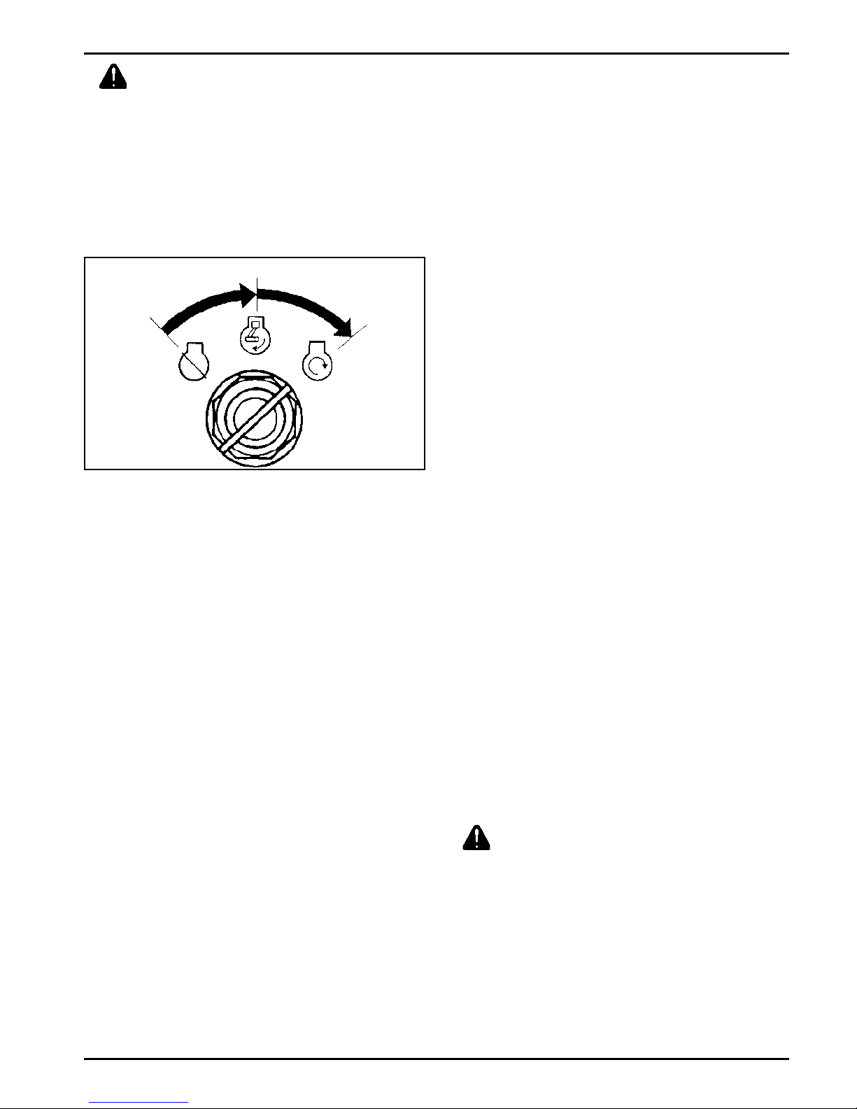
For an Electric Start Engine Activate the
starter switch. Release the switch as soon as the
engine starts.
On
Off
Figure 8. Electric Start Engine Starter Switch.
NOTE: Do not crank the engine continuously for
more than 10 seconds at a time. If the
engine does not start, allow a 60 second
cool down period between starting
attempts. Failure to follow these
guidelines can burn out the starter motor.
Start
3. Move the throttle control to the slow position.
Turn key switch or on/off switch to off position.
4. Close fuel shut-off valve.
Battery
A 12 volt battery is normally used. Refer to the
operating instructions of the equipment this engine
powers for specific battery requirements.
If the battery charge is not sufficient to crank the
engine, recharge the battery (see page 12).
Operating
Angle of Operation
This engine will operate continuously at angles up
to 20°. Check oil level to assure crankcase oil is up to
the point of overfilling the filler neck.
Refer to the operating instructions of the equipment
this engine powers. Because of equipment design or
application, there may be more stringent restrictions
regarding the angle of operation.
NOTE: If the engine develops sufficient speed to
disengage the starter but does not keep
running (a false start), the engine rotation
must be allowed to come to a complete
stop before attempting to restart the
engine. If the start is engaged while the
flywheel is rotating, the starter pinion and
flywheel ring gear may clash, resulting in
damage to the starter.
If the starter does not turn the engine over, shut off
starter immediately. Do not make further attempts to
start the engine until the condition is corrected. Do not
jump start using another battery (refer to "Battery").
See your Kohler Engine Service Dealer for trouble
analysis.
4. For a Cold Engine Gradually return the choke
control to the off position after the engine starts
and warms up.
The engine/equipment may be operated during the
warm up period, but it may be necessary to leave
the choke partially on until the engine warms up.
NOTE: Do not operate this engine continuously at
angles exceeding 20° in any direction. Engine
damage could result from insufficient
lubrication.
Cooling
NOTE: If debris builds up on the grass screen or
other cooling air intake areas, stop the engine
immediately and clean. Operating the engine
with blocked or dirty air intake and cooling
areas can cause extensive damage due to
overheating.
WARNING: Hot Parts!
Engine components can get extremely hot from
operation. To prevent severe burns, do not touch these
areas while the engine is runningor immediately after
it is turned off. Never operate the engine with heat
shields or guards removed.
Engine Speed
NOTE: Do not tamper with the governor setting to
increase the maximum engine speed.
Overspeed is hazardous and will void the
engine warranty.
7
Page 18
Maintenance Instructions
Maintenance, repair, or replacement of the emission control devices and systems, which are being done at
the customers expense, may be performed by any non-road engine repair establishment or individual.
Warranty repairs must be performed by an authorized Kohler service outlet.
WARNING: Accidental Starts!
Disabling engine. Accidental starting can cause severe injury or death. Before working on the engine or
equipment, disable the engine as follows: 1) Disconnect the spark plug lead(s). 2) Disconnect negative (-) battery
cable from battery.
Maintenance Schedule
These required maintenance procedures should be performed at the frequency stated in the table. They should
also be included as part of any seasonal tune-up.
Maintenance RequiredFrequency
Fill fuel tank.
Check oil level.
Check air cleaner for dirty, loose, or damaged parts.
Daily or Before
Starting Engine
Check air intake and cooling areas, clean as necessary.
Check fuel hose for cracks or damage. Replace if necessary.
Check exhaust system for leakage. Retighten or replace gasket if necessary.
Check choke operation.
Check retractable starter operation.
Every 25 Hours
Service precleaner element. Replace if necessary.
Change oil.
Replace air cleaner element.
1
Remove cooling shrouds and clean cooling areas.
Every 100 Hours
Check all fittings and fasteners.
Clean fuel valve shut-off filter. Replace if necessary.
Check muffler screen/spark arrestor. Clean/replace if necessary.
Check spark plug condition, adjust gap, and clean. Replace if necessary.
Check and adjust valve clearance when engine is cold.
Annually or
Every 300 Hours
Check and adjust idle speed.
Service starter motor drive, if so equipped.
Check cooling fan for damage.
Have combustion chamber decarbonized.
2
2
¹Perform these maintenance procedures more frequently under extremely dusty, dirty conditions.
²Have a Kohler Engine Service Dealer perform this service.
1
1
2
1
1
2
Check Oil Level
The importance of checking and maintaining the proper
oil level in the crankcase cannot be overemphasized.
Check oil BEFORE EACH USE as follows:
1. Make sure the engine is stopped, level, and is
cool so the oil has had time to drain into the sump.
2. To keep dirt, debris, etc., out of the engine, clean
the area around the oil fill/check plug before
removing it.
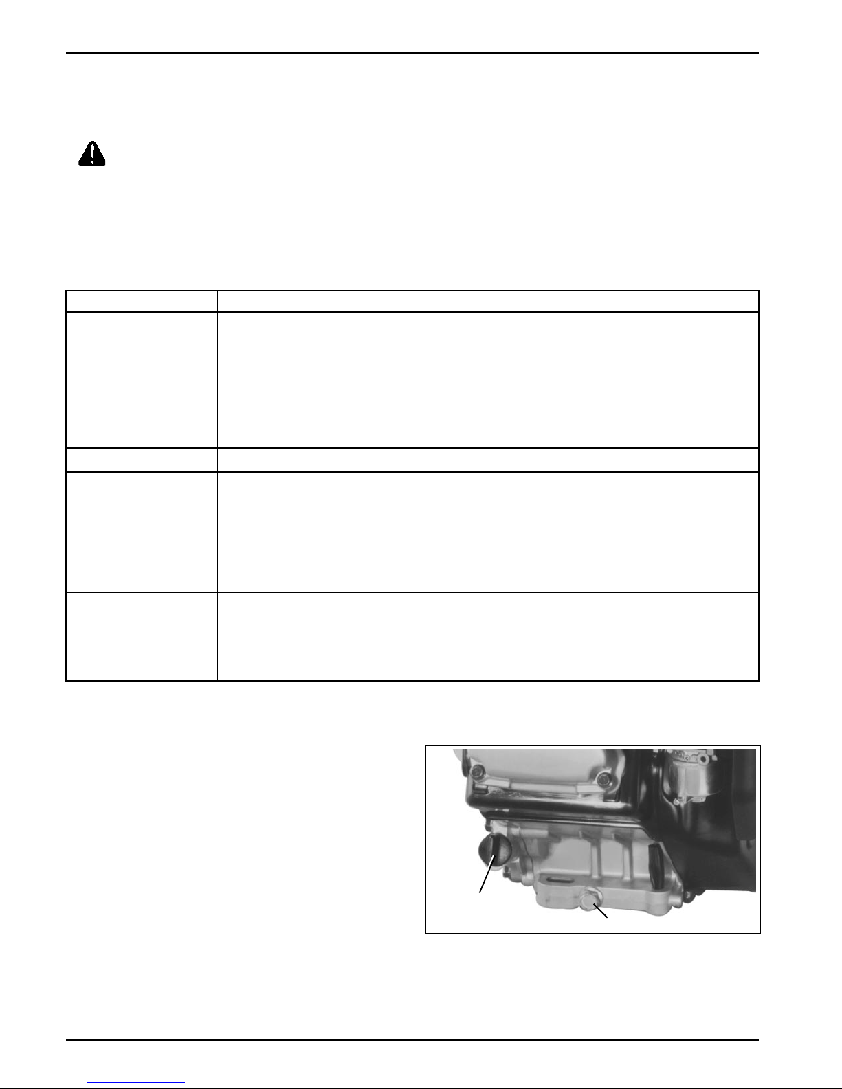
3. Unthread and remove the oil fill/check plug.
4. The level should be up to but not over, the point of
overflowing the filler neck.
8
Oil Fill/
Check Plug
Oil Drain Plug
Figure 9. Location of Oil Drain and Check Plugs.
Page 19
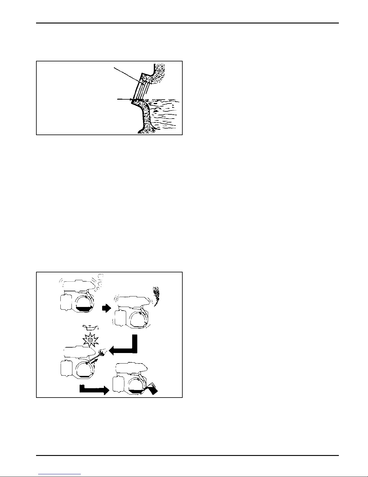
NOTE: Just because you can see oil in the crankcase
doesn't mean the level is in the safe range.
Bring the level up to the point of overflowing
the filler neck.
Filler Neck
Bring Level Up To
Point of Overflow
(Cutaway Showing
Proper Oil Level)
Figure 10. Proper Oil Level.
5. If the level is low, add oil of the proper type, up to
the point of overflowing the filler neck. (Refer to
Oil Type on page 4.) Always check the level
before adding more oil.
NOTE: To prevent extensive engine wear or
damage, always maintain the proper oil
level in the crankcase. Never operate the
engine with the oil level below the point of
overflowing the filler neck.
NOTE: If the engine stalls or does not start, turn the
engine switch to on position and then pull
the recoil starter or attempt to start engine. If
the oil warning light flickers for a few seconds,
the engine oil is insufficient. Add oil and
restart.
NOTE: Make sure the oil level is checked BEFORE
EACH USE and is maintained up to the point
of overflowing the filler neck.
Change Oil
For a new engine, change oil after the first 20 hours
of operation. Thereafter, change oil after every 100
hours of operation.
For an overhauled engine, use 10W-30 weight
service class SG, SH, SJ or higher oil for the first 20
hours of operation. Change the oil after this initial run-
in period. Refill with service class SG, SH, SJ or higher
oil as specified in the Viscosity Grades table (Figure
2) on page 4.
Change the oil while the engine is still warm. The oil will
flow freely and carry away more impurities. Make sure
the engine is level when filling, checking, or changing
the oil.
Oil Sentry
Engines are equipped with an Oil Sentry oil monitor.
When the oil level falls below the safe level, the engine
stops automatically. Unless you refill with oil, the
engine will not start again. See Figure 11.
Figure 11.
Change the oil as follows (see Figure 9):
1. To keep dirt, debris, etc., out of the engine, clean
the area around the oil fill cap/dipstick before
removing it.
2. Remove the oil drain plug and oil fill/check plug.
Be sure to allow ample time for complete
drainage.
3. Reinstall the drain plug. Make sure it is tightened
to 17.6 N·m (13 ft. lb.) torque.
4. Fill the crankcase, with new oil of the proper type,
up to the point of overflowing the filler neck. Refer
to Oil Type on page 4. Always check the level
before adding more oil.
5. Reinstall the oil fill/check plug and tighten securely.
NOTE: To prevent extensive engine wear or
damage, always maintain the proper oil
level in the crankcase. Never operate the
engine with the oil level below the point of
overflowing the filler neck.
9
Page 20
Reduction Systems
2:1 Reduction Systems
All 2:1 reduction systems are lubricated by the
crankcase oil of the engine through special openings in
the closure plate. No special maintenance or service is
necessary. Check and maintain the oil level as outlined
on pages 8 and 9.
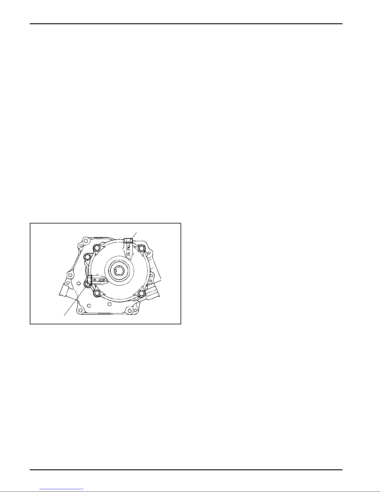
6:1 Reduction Systems
CS4 and CS6: Use an internal pinion and ring gear
system, independent of, and separated from the main
crankcase lubrication. See Figure 12. Use the same
weight oil in the reduction system that is being used in
the crankcase. Reduction System Capacity = .15
liters (5.07 fl. oz.). Change the reduction system oil
every 300 hours as follows:
1. Drain old oil out through the oil level/drain plug, tip
engine as required.
NOTE: Operating the engine with loose or damaged
air cleaner components could allow unfiltered
air into the engine causing premature wear
and failure.
Service Precleaner
Wash and reoil the precleaner every 25 hours of
operation (more often under extremely dusty or dirty
conditions).
1. Remove the outer cover of the air cleaner
assembly and access the element.
2. Remove the precleaner from the paper element.
3. Wash the precleaner in warm water with
detergent. Rinse the precleaner thoroughly until all
traces of detergent are eliminated. Squeeze out
excess water (do not wring). Allow the precleaner
to air dry.
2. Engine must be level. Fill with new oil through the
oil fill plug hole on top until the oil level is up to the
bottom of the oil level/drain plug hole. Reinstall
both plugs securely.
Oil Fill Plug
Oil Level/Drain Plug
Figure 12. CS4 and CS6 6:1 Reduction System.
CS8.5, CS10, and CS12: Use a gear reduction system
which is lubricated by the crankcase oil of the engine
through holes in the closure plate. No special
maintenance or service is necessary.
Service Precleaner and Air Cleaner Element
This engine is equipped with a replaceable, high
density paper air cleaner element. All engines are also
equipped with an oiled, foam precleaner which covers
the paper element. See Figure 13 on page 11.
Check the air cleaner daily or before starting the
engine. Check for a buildup of dirt and debris around
the air cleaner system. Keep this area clean. Also
check for loose or damaged components. Replace all
bent or damaged air cleaner components.
4. Saturate the precleaner with new engine oil and
squeeze out all excess oil.
5. Reinstall the precleaner over the paper element.
6. Reinstall and secure the air cleaner cover.
Service Paper Element
Every 100 hours of operation (more often under
extremely dusty or dirty conditions), replace the paper
element.
1. Remove the outer cover of the air cleaner
assembly and access the element/precleaner
assembly. Remove the wing nut securing the
element assembly, or pull the complete assembly
out of the cover/housing (some Heavy Duty Air
Cleaners). Separate the precleaner from the
element and service as outlined above.
2. Do not wash the paper element or use
pressurized air, as this will damage the element.
Replace a dirty, bent, or damaged element with a
genuine Kohler element. Handle new elements
carefully; do not use if the sealing surfaces are
bent or damaged.
3. When servicing the air cleaner, check the air
cleaner base. Make sure it is secured and not
bent or damaged. Check the air cleaner cover/
housing for damage or improper fit. Replace all
bent or damaged air cleaner components.
On Standard Air Cleaner Systems:
Before air cleaner is reassembled make sure
rubber seal is in position around stud. Inspect seal
and replace if its condition is questionable in any
way.
10
Page 21
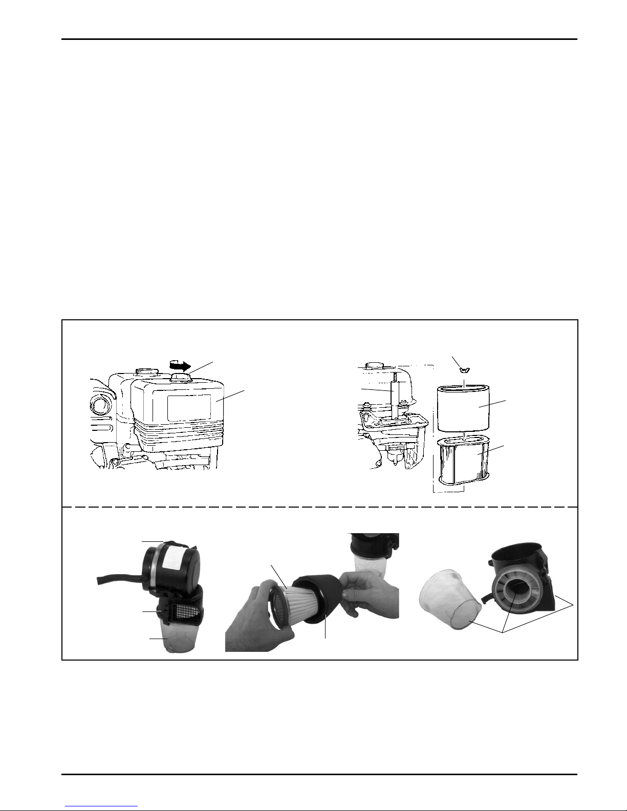
On Heavy Duty Air Cleaner Systems:
Remove and clean the lower dirt/swirl chamber.
Make sure the openings near the base of
chamber and in the air cleaner cover/housing, are
not blocked or restricted. See Figure 13.
Every 100 hours of operation (more often under
extremely dusty, dirty conditions), remove the blower
housing and other cooling shrouds. Clean the cooling
fins and external surfaces as necessary. Make sure the
cooling shrouds are reinstalled.
4. Position the paper element on base and secure
with wing nut, then install the precleaner over the
element. If element is not secured with a wing nut,
place the precleaner over the element and install it
as an assembly into the cover/housing. Narrow
end must be installed first and face away the from
base.
5. Reinstall and secure the outer cover/housing.
Clean Air Intake/Cooling Areas
To ensure proper cooling, make sure the grass screen,
cooling fins, and other external surfaces of the engine
are kept clean at all times.
Standard Dual Air Cleaner System
Knob
Air Cleaner
Cover
NOTE: Operating the engine with a blocked grass
screen, dirty or plugged cooling fins, and/or
cooling shrouds removed, will cause engine
damage due to overheating.
Ignition System
This engine is equipped with a dependable electronic
magneto ignition system. Other than periodically
checking/replacing the spark plug, no maintenance,
timing, or adjustments are necessary or possible with
this system.
In the event starting problems should occur which are
not corrected by replacing the spark plug, see your
Kohler Engine Service Dealer for trouble analysis.
Wing Nut
Seal
Precleaner
Heavy Duty Air Cleaner System
Latches
Element
Air Cleaner
Cover/
Housing
Lower Swirl/Dirt
Chamber
Figure 13. Air Cleaner System Components.
Precleaner
Air Cleaner
Element
Openings must not be
blocked or restricted
11
Page 22
Check Spark Plug
Annually or every 100 hours of operation, remove the
spark plug, check condition, and reset the gap or
replace with new plug as necessary. The original plug
is an NGK BPR4ES. The Champion® equivalent of that
NGK plug is RN14YC. The service replacement is
Champion® RC14YC (Kohler part No. 66 132 01-S).
Equivalent alternate brand plugs can also be used.
1. Before removing the spark plug, clean the area
around the base of the plug to keep dirt and debris
out of the engine.
2. Remove the plug and check its condition.
Replace the plug if worn or reuse is questionable.
NOTE: Do not clean the spark plug in a machine
using abrasive grit. Some grit could
remain in the spark plug and enter the
engine causing extensive wear and
damage.
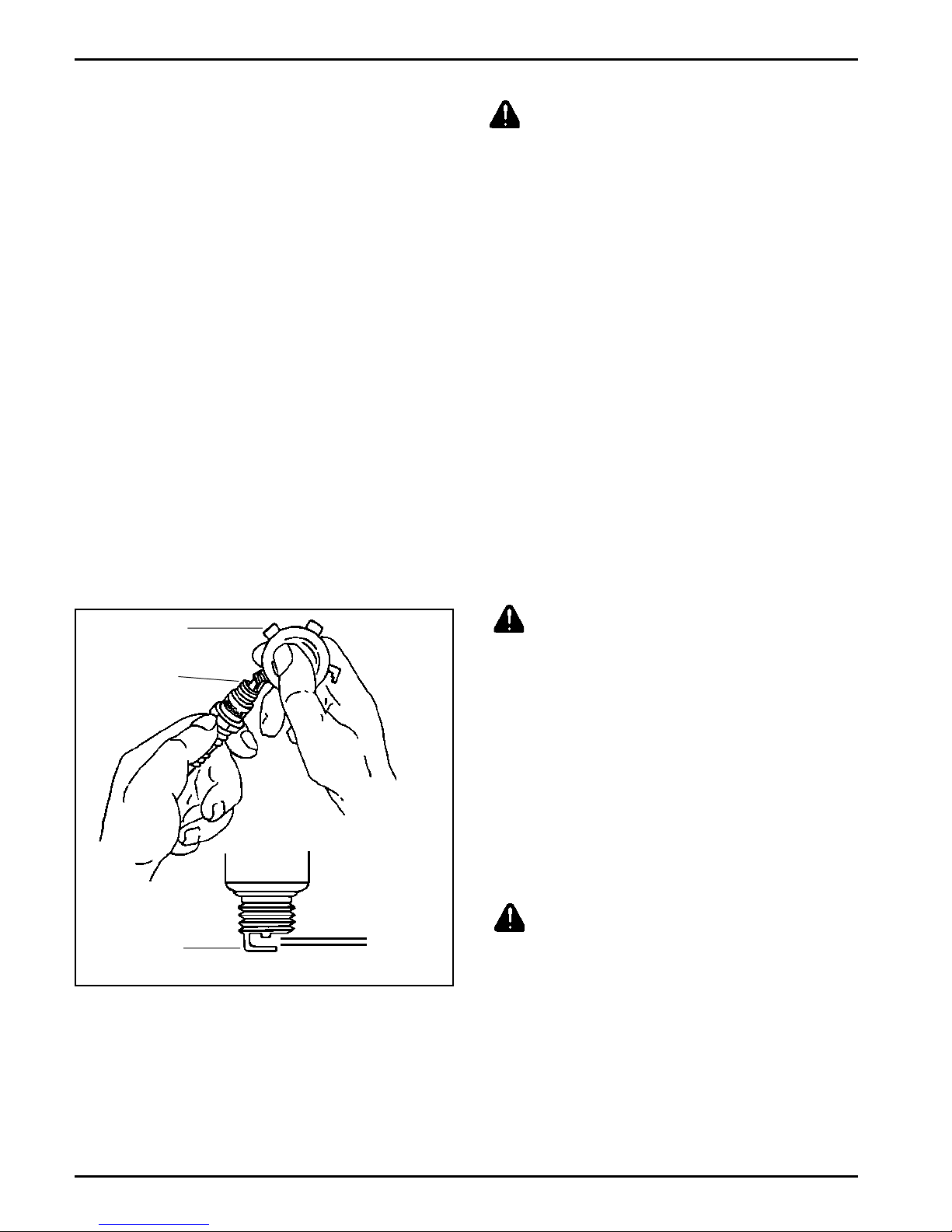
3. Check the gap using a wire feeler gauge. Adjust
the gap to 0.76 mm (0.030 in.) by carefully
bending the ground electrode. See Figure 14.
Battery Charging
WARNING: Explosive Gas!
Batteries produce explosive hydrogen gas while being
charged. To prevent a fire or explosion, charge
batteries only in well ventilated areas. Keep sparks,
open flames, and other sources of ignition away from
the battery at all times. Keep batteries out of the reach
of children. Remove all jewelry when servicing
batteries.
Before disconnecting the negative (-) ground cable,
make sure all switches are OFF. If ON, a spark will
occur at the ground cable terminal which could cause
an explosion if hydrogen gas or gasoline vapors are
present.
NOTE: Do not apply 12 volt DC to kill terminal of
ignition module.
Fuel Valve
Engines are equipped with a fuel valve and integral
screen filter located at the outlet of the fuel tank. See
Figure 15. It controls and filters fuel flow from the tank
to the carburetor.
4. Reinstall the spark plug into the cylinder head.
Torque the spark plug to 20 N·m (14 ft. lb.).
Wire Gauge
Spark Plug
Ground
Electrode
Figure 14. Servicing Spark Plug.
0.76 mm
(0.030 in.) Gap
Every 100 hours of operation clean filter screen and
cup of any accumulated debris as follows:
CAUTION!
Never use or be near fuel or solvent while smoking or
in the vicinity of an open flame.
1. Stop the engine.
2. Turn the fuel valve lever to off.
3. Remove the fuel valve cup and gasket.
4. Clean the cup with solvent and wipe it off.
5. Check the gasket, replace if damaged.
6. Reinstall the gasket and fuel valve cup.
CAUTION!
Be sure the fuel valve cup is tightened securely.
12
Page 23
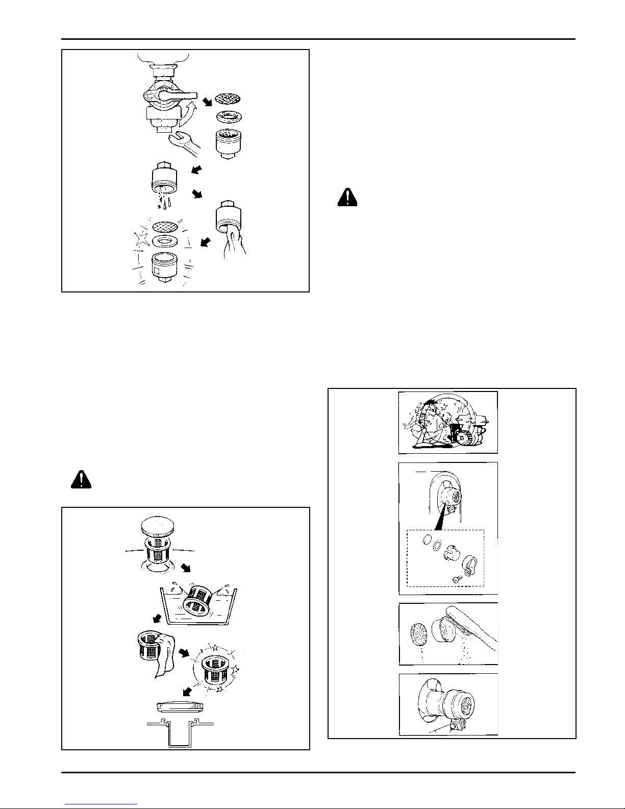
Figure 15.
Fuel Tank Filter
A serviceable fuel tank filter is located under the fuel
tank cap, in the filler neck.
Muffler Screen and Spark Arrestor
Engines are equipped with a muffler screen and spark
arrestor for operational and environmental safety. One
of two configurations will be used, determined by the
engine model involved.
Every 100 hours of operation, remove and clean or
replace the muffler screen and/or spark arrestor
following the instructions below.
Muffler Screen CS4,CS6
CAUTION!
The engine and muffler will be very hot after the engine
has been run.
Avoid touching the engine and muffler while they are
still hot, with any part of your body or clothing.
1. Remove the muffler screen.
2. Clean the carbon deposits out of the muffler
screen using a wire brush.
3. Check the muffler screen, replace if damaged.
Daily or as required clean filter of any accumulation
as follows:
1. Remove the fuel tank cap and filter.
2. Clean the filter with solvent, replace if damaged.
3. Wipe the filter and insert it.
CAUTION!
Be sure the tank cap is tightened securely.
4. Install the muffler screen.
Figure 16.
Figure 17. Muffler Screen.
13
Page 24
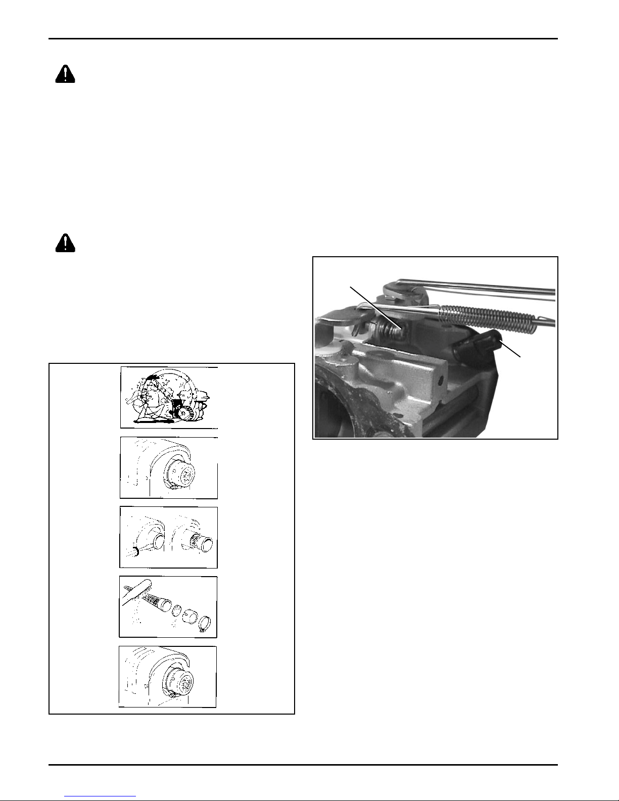
Muffler Screen and Spark Arrestor CS8.5,CS10,CS12
CAUTION!
The engine and muffler will be very hot after the engine
has been run. Avoid touching the engine and muffler
while they are still hot, with any part of your body or
clothing.
1. Remove the muffler screen.
2. Remove the spark arrestor using a flatblade
screwdriver.
3. Clean the carbon deposits out of the muffler
screen and spark arrestor using a wire brush.
CAUTION!
When cleaning, use the wire brush lightly to avoid
damaging or scratching of the muffler screen and
spark arrestor.
4. Check the muffler screen and spark arrestor,
replace if damaged.
5. Install the spark arrestor and muffler screen.
Carburetor Troubleshooting and
Adjustments
NOTE: Carburetor adjustments should be made only
after the engine has warmed up.
The carburetor is designed to deliver the correct
fuel-to-air mixture to the engine under all operating
conditions. The high idle mixture is set at the factory
and cannot be adjusted. The low idle fuel adjusting
needle is also set at the factory and has a limiting cap.
It normally does not need adjustment.
If the engine is hard to start, runs roughly, or stalls at
low idle speed, it may be necessary to adjust or
service the carburetor.
Idle Speed
Screw
Idle Fuel
Needle
Figure 19. Carburetor.
Troubleshooting
If engine troubles are experienced that appear to be
fuel system related, check the following areas before
adjusting the carburetor.
Make sure the fuel tank is filled with clean, fresh
gasoline.
Make sure the fuel tank cap vent is not blocked
and that it is operating properly.
Make sure the fuel shut-off valve is fully open.
Make sure fuel shut-off valve strainer, and in-line
fuel filter (if used) are clean and unobstructed.
Clean or replace as necessary.
Figure 18. Muffler Screen and Spark Arrestor.
14
Page 25

Make sure fuel is reaching the carburetor. This
includes checking the fuel lines and components
for restrictions or problems. Replace as
necessary.
Make sure On-Off switch is functioning properly.
Make sure the air cleaner element is clean and all
air cleaner components are fastened securely.
If, after checking the items listed above, the engine is
hard to start, runs roughly, or stalls at low idle speed, it
may be necessary to adjust or service the carburetor.
Adjust Carburetor
NOTE: Certified engines have a limiter cap on the idle
fuel adjusting needle. Adjustment can only be
performed within the limits allowed by the cap.
1. Start the engine and run at half throttle for 5 to 10
minutes to warm up. The engine must be warm
before making final settings.
2. Low Idle Fuel Needle Setting: Place the throttle
into the idle or slow position. Turn the low
idle fuel adjusting needle/cap in or out within
adjustment range, to obtain the best low speed
performance.
3. Low Idle Speed Setting: Place the throttle control
into the idle or slow position. Set the low idle
speed to 2000 RPM* (+ 150 RPM) by turning the
low idle speed adjusting screw in or out. Check
the speed using a tachometer.
*NOTE: The actual low idle speed depends on the
application refer to equipment
manufacturer's recommendations. The
recommended low isle speed for basic
engines is 2000 RPM. To ensure best
results when setting the low idle fuel
needle, the low idle speed must not
exceed 2000 RPM (+ 150 RPM).
Troubleshooting
When troubles occur, be sure to check the simple causes which, at first, may seem too obvious to be considered.
For example, a starting problem could be caused by an empty fuel tank. Some common causes of engine troubles
are listed in the following table.
Do not attempt to service or replace major engine components, or any items that require special timing or
adjustment procedures. Have your Kohler Engine Service Dealer do this work.
Possible Cause No Improper Dirt In Dirty Incorrect Engine Dirty Air Faulty
Problem Fuel Fuel Fuel Line Grass Screen Oil Level Overloaded Cleaner Spark Plug
Will Not Start
Hard Starting
Stops Suddenly
Lacks Power
Operates Erratically
Knocks or Pings
Skips or Misfires
Backfires
Overheats
High Fuel Consumption
15
Page 26

Storage
If the engine will be out of service for two months or
more, use the following storage procedure:
1. Clean the exterior surfaces of the engine.
2. Change the oil while the engine is still warm from
operation. See Change Oil on page 9.
3. The fuel system must be completely emptied, or
the gasoline must be treated with a stabilizer to
prevent deterioration. If you choose to use a
stabilizer, follow the manufacturers
recommendations, and add the correct amount for
the capacity of the fuel system. Fill the fuel tank
with clean, fresh gasoline. Run the engine for 2-3
minutes to get stabilized fuel into the carburetor.
To empty the system, run the engine until the tank
and system are empty.
4. Remove the spark plug. Add one tablespoon of
engine oil into the spark plug hole. Install the plug,
but do not connect the plug lead. Crank the engine
two or three revolutions.
5. Remove the spark plug. Cover the spark plug hole
with your thumb, and turn the engine over until the
piston is at the top of its stroke. (Pressure against
the thumb is greatest.) Reinstall the plug, but do
not connect the plug lead.
6. Store the engine in a clean, dry place.
Parts Ordering
The engine Specification, Model, and Serial Numbers
are required when ordering replacement parts from
your Kohler Engine Service Dealer. These numbers are
found on the identification plate which is affixed to the
engine shrouding. Include letter suffixes if there are
any. See Engine Identification Numbers on page 5.
Always insist on genuine Kohler parts. All genuine
Kohler parts meet strict standards for fit, reliability, and
performance.
Major Repair
Major repair information is available in Kohler Engine
Service Manuals. However, major repair generally
requires the attention of a trained mechanic and the
use of special tools and equipment. Your Kohler
Engine Service Dealer has the facilities, training, and
genuine Kohler replacement parts necessary to
perform this service. For Sales & Service assistance
call 1-800-544-2444 (U.S. & Canada) or contact your
Kohler Engine Dealer or Service Distributor, they're in
the Yellow Pages under Engines-Gasoline.
Model Designation
Model CS4T for example: C designates Command
engine, S designates slanted cylinder configuration,
and 4 designates horsepower. A suffix letter designates
a specific version as follows:
Suffix Designates
T Retractable Start
S Electric Start
G Tapered Crankshaft
P Threaded Crankshaft
R Gear Reduction (2:1 or 6:1)
16
Page 27

Specifications
Model: .......................................................................... CS4 ............. CS6 ........ CS8.5 .......... CS8.5 ........... CS10 ........... CS12
Spec. Number .......................................................... 90xxxx ......... 91xxxx ....... 95xxxx .......... 92xxxx......... 93xxxx ......... 94xxxx
Bore: .................................................. mm(in.) ..... 56(2.20) ....... 66(2.60) .....75(2.95) ....... 78(3.07) ....... 78(3.07) ...... 85(3.35)
Stroke: ................................................ mm(in.) ..... 50(1.97) ....... 50(1.97) .....57(2.44) ....... 63(2.48) .......63(2.48) ...... 63(2.48)
Displacement: ................................... cm3(in.3) ... 123(7.51) ...171(10.44) .. 251(15.3) ... 301(18.37) ...301(18.37) .. 357(21.79)
*Power (@ 3600 RPM): .................... kW(HP) ...... 2.98(4*) ....... 4.47(6*) .... 5.4(8.5*) .....6.33(8.5*) ..... 7.45(10*) ..... 8.95(12*)
Max. Torque (@ 2400 RPM): ...... N·m(ft. lbs.) .....#7.5(5.5) ...... 11.0(8.1) . 16.5(12.2) .... 19.9(14.7) .... 19.9(14.7) ... 25.0(18.4)
Compression Ratio: .................................................... 8.3:1 ............ 8.5:1 .......... 8.3:1 ............ 8.1:1 ............ 8.1:1 ............8.1:1
Weight:............................................... kg(lbs.) .. 17.5(38.6) .... 17.5(38.6) .....26(57.2) .... 31.9(70.5) ....31.9(70.5) ... 31.9(70.5)
Oil Capacity: ...................................L(U.S. qt.) ...... 0.6(0.6) ........ 0.6(0.6) .... 1.0(1.06) ....... 1.1(1.2) ........1.1(1.2) ....... 1.1(1.2)
Fuel Tank Capacity: ....................... L(U.S. qt.) ...... 3.9(4.1) ........3.9(4.1) ......6.0(6.3) ........ 6.9(7.3) ........6.9(7.3) ....... 6.9(7.3)
Exhaust Emission Control System:..................... EM
*Horsepower ratings are established in accordance with Society of Automotive Engineers Small Engine Test
Code J1349 GROSS. Kohler Co. reserves the right to change product specifications, design, and standard
equipment without notice and without incurring obligation.
#
Max. Torque obtained at engine speed of 2600 RPM.
LIMITED 2 YEAR COMMAND ENGINE WARRANTY
We warrant to the original consumer that each new COMMAND engine sold by us will be free from manufacturing defects in materials or
workmanship in normal service for a period of two (2) years from date of purchase, provided it is operated and maintained in accordance
with Kohler Co.s instructions and manuals.
Our obligation under this warranty is expressly limited, at our option, to the replacement or repair at Kohler Co., Kohler, Wisconsin 53044,
or at a service facility designated by us of such parts as inspection shall disclose to have been defective.
EXCLUSIONS:
This warranty does not apply to defects caused by casualty or unreasonable use, including faulty repairs by others and failure to provide
reasonable and necessary maintenance.
The following items are not covered by this warranty:
Engine accessories such as fuel tanks, clutches, transmissions, power-drive assemblies, and batteries, unless supplied or installed by
Kohler Co. These are subject to the warranties, if any, of their manufacturers.
WE SHALL NOT BE LIABLE FOR SPECIAL, INDIRECT, INCIDENTAL, OR CONSEQUENTIAL DAMAGES OF ANY KIND, including but
not limited to labor costs or transportation charges in connection with the repair or replacement of defective parts.
ANY IMPLIED OR STATUARY WARRANTIES, INCLUDING WARRANTY OF MERCHANTABILITY OR FITNESS FOR A PARTICULAR
PURPOSE, ARE EXPRESSLY LIMITED TO THE DURATION OF THIS WRITTEN WARRANTY. We make no other express warranty, nor
is any one authorized to make any in our behalf.
Some states do not allow limitations on how long an implied warranty lasts, or the exclusion or limitation of incidental or consequential
damages, so the above limitation or exclusion may not apply to you.
This warranty gives you specific legal rights, and you may also have other rights which vary from state to state.
TO OBTAIN WARRANTY SERVICE:
Purchaser must bring the engine to an authorized Kohler service facility. For the facility nearest you, consult your Yellow Pages or write
Kohler Co., Attn: Engine Warranty Service Dept., Kohler, Wisconsin, 53044.
ENGINE DIVISION, KOHLER CO., KOHLER, WISCONSIN 53044
17
Page 28

KOHLER CO.
FEDERAL AND CALIFORNIA EMISSION CONTROL SYSTEMS
LIMITED WARRANTY
SMALL OFF-ROAD ENGINES
The U.S. Environmental Protection Agency (EPA), the California Air Resources Board (CARB), and Kohler Co. are pleased to explain the
Federal and California Emission Control Systems Warranty on your small off-road equipment engine. For California, engines produced in 1995
and later must be designed, built and equipped to meet the states stringent anti-smog standards. In other states, 1997 and later model year
engines must be designed, built and equipped, at the time of sale, to meet the U.S. EPA regulations for small non-road engines. The engine
must be free from defects in materials and workmanship which cause it to fail to conform with U.S. EPA standards for the first two years of
engine use from the date of sale to the ultimate purchaser. Kohler Co. must warrant the emission control system on the engine for the period of
time listed above, provided there has been no abuse, neglect or improper maintenance.
The emission control system may include parts such as the carburetor or fuel injection system, the ignition system, and catalytic converter.
Also included are the hoses, belts and connectors and other emission related assemblies.
Where a warrantable condition exists, Kohler Co. will repair the engine at no cost, including diagnosis (if the diagnostic work is performed at an
authorized dealer), parts and labor.
MANUFACTURERS WARRANTY COVERAGE
Engines produced in 1995 or later are warranted for two years in California. In other states, 1997 and later model year engines are warranted for
two years. If any emission related part on the engine is defective, the part will be repaired or replaced by Kohler Co. free of charge.
OWNERS WARRANTY RESPONSIBILITIES
(a) The engine owner is responsible for the performance of the required maintenance listed in the owners manual. Kohler Co. recommends
that you retain all receipts covering maintenance on the engine, But Kohler Co. cannot deny warranty solely for the lack of receipts or for
your failure to assure that all scheduled maintenance was performed.
(b) Be aware, however, that Kohler Co. may deny warranty coverage if the engine or a part has failed due to abuse, neglect, improper
maintenance or unapproved modifications.
(c) For warranty repairs, the engine must be presented to a Kohler Co. service center as soon as a problem exists. Call 1-800-544-2444 or
access our web site at: www.kohlerengines.com, for the names of the nearest service centers. The warranty repairs should be completed
in a reasonable amount of time, not to exceed 30 days.
If you have any questions regarding warranty rights and responsibilities, you should contact Kohler Co. at 1-920-457-4441 and ask for an
Engine Service representative.
COVERAGE
Kohler Co. warrants to the ultimate purchaser and each subsequent purchaser that the engine will be designed, built and equipped, at the time
of sale, to meet all applicable regulations. Kohler Co. also warrants to the initial purchaser and each subsequent purchaser, that the engine is
free from defects in materials and workmanship which cause the engine to fail to conform with applicable regulations for a period of two years.
Engines produced in 1995 or later are warranted for two years in California. For 1997 and later model years, EPA requires manufacturers to
warrant engines for two years in all other states. These warranty periods will begin on the date the engine is purchased by the initial purchaser. If
any emission related part on the engine is defective, the part will be replaced by Kohler Co. at no cost to the owner. Kohler Co. is liable for
damages to other engine components caused by the failure of a warranted part still under warranty.
Kohler Co. shall remedy warranty defects at any authorized Kohler Co. engine dealer or warranty station. Warranty repair work done at an
authorized dealer or warranty station shall be free of charge to the owner if such work determines that a warranted part is defective.
Listed below are the parts covered by the Federal and California Emission Control Systems Warranty. Some parts listed below may require
scheduled maintenance and are warranted up to the first scheduled replacement point for that part. The warranted parts are:
Oxygen sensor (if equipped) Ignition module(s) with high tension lead
Intake manifold (if equipped) Gaseous fuel regulator (if equipped)
Exhaust manifold (if equipped) Electronic control unit (if equipped)
Catalytic muffler (if equipped) Carburetor or fuel injection system
Fuel metering valve (if equipped) Fuel lines (if equipped)
Spark advance module (if equipped) Air filter, fuel filter, and spark plugs (only
Crankcase breather to first scheduled replacement point)
Continued on next page.
18
Page 29

LIMITATIONS
This Emission Control Systems Warranty shall not cover any of the following:
(a) repair or replacement required because of misuse or neglect, improper maintenance, repairs improperly performed or replacements not
conforming to Kohler Co. specifications that adversely affect performance and/or durability and alterations or modifications not
recommended or approved in writing by Kohler Co.,
(b) replacement of parts and other services and adjustments necessary for required maintenance at and after the first scheduled replacement
point,
(c) consequential damages such as loss of time, inconvenience, loss of use of the engine or equipment, etc.,
(d) diagnosis and inspection fees that do not result in eligible warranty service being performed, and
(e) any add-on or modified part, or malfunction of authorized parts due to the use of add-on or modified parts.
MAINTENANCE AND REPAIR REQUIREMENTS
The owner is responsible for the proper use and maintenance of the engine. Kohler Co. recommends that all receipts and records covering the
performance of regular maintenance be retained in case questions arise. If the engine is resold during the warranty period, the maintenance
records should be transferred to each subsequent owner. Kohler Co. reserves the right to deny warranty coverage if the engine has not been
properly maintained; however, Kohler Co. may not deny warranty repairs solely because of the lack of repair maintenance or failure to keep
maintenance records.
Normal maintenance, replacement or repair of emission control devices and systems may be performed by any repair establishment or
individual; however, warranty repairs must be performed by a Kohler authorized service center. Any replacement part or service that is
equivalent in performance and durability may be used in non-warranty maintenance or repairs, and shall not reduce the warranty obligations of the
engine manufacturer.
19
Page 30

FOR SALES AND SERVICE INFORMATION
IN U.S. AND CANADA, CALL
ENGINE DIVISION, KOHLER CO., KOHLER, WISCONSIN 53044
1-800-544-2444
FORM NO.: TP-2494
ISSUED: 8/98
REVISED: 8/01
MAILED:
 Loading...