

Page 1
®
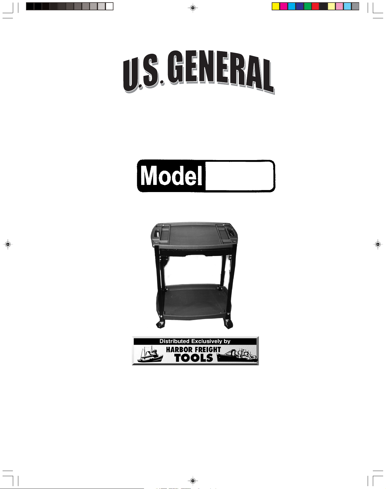
110 PIECE TOOL AND
SERVICE CART
90722
ASSEMBLY & OPERATING INSTRUCTIONS
Copyright© 2003 by Harbor Freight Tools®. All rights reserved. No portion of this manual or
any artwork contained herein may be reproduced in any shape or form without the
express written consent of Harbor Freight Tools.
For technical questions and replacement parts please call 1-800-444-3353.
90722 Tool and Service Cart.p65 9/30/03, 11:22 AM1
3491 Mission Oaks Blvd., Camarillo, CA 93011
Visit our Web Site at www.harborfreight.com
Page 2
THANK YOU for choosing a HARBOR FREIGHT TOOLS product. For future reference, please
complete the owner’s record below:
Model
______________ Serial No._____________ Purchase Date_______________
SAVE THE RECEIPT, WARRANTY AND THESE INSTRUCTIONS. It is important that you read the
entire manual to become familiar with the unit BEFORE you begin assembly.
Technical Specifications
Material: Drop forged steel
Caster Assembly: (4) Swivel Casters, 2-1/2” diameter
Top Shelf: 23-1/2” x 16-1/2” x 1-1/2”
Bottom Shelf: 23-1/2” x 16-1/2” x 2”
Tool Drawer: 18” x 14-1/2” x 2”
Maximum Weight Capacity: 100 lbs. bottom shelf; 30 lbs. top shelf (evenly distributed)
Safety Warnings and Precautions
WARNING: When using product, basic safety precautions should always be followed to reduce
the risk of personal injury and damage to equipment.
Read all instructions before using this product!
1. Keep work area clean. Cluttered areas invite injuries.
2. Observe work area conditions. Do not use machines or power tools in damp or wet locations.
Keep work area well lighted.
3. Keep children away. Children must never be allowed in the work area. Do not let them handle
machines, tools, or extension cords.
4. Store idle equipment. When not in use, tools must be stored in a dry location to inhibit rust.
Always lock up tools and keep out of reach of children.
5. Do not force product. It will do the job better and more safely at the rate for which it was
intended. Do not use inappropriate attachments in an attempt to exceed the product capacity.
6. Use the right product for the job. Do not attempt to force a small product or attachment to do
the work of a larger industrial product. There are certain applications for which this product was
designed. Do not modify this product and do not use this product for a purpose for which it was
not intended.
7. Dress properly. Do not wear loose clothing or jewelry as they can be caught in moving parts.
8. Use eye and ear protection. Always wear ANSI approved impact safety goggles when
assembling the product. Wear gloves to protect hands and avoid pinching fingers.
SKU 90722 Page 2
90722 Tool and Service Cart.p65 9/30/03, 11:22 AM2
Page 3
9. Check for damaged parts. Before using any product, any part that appears damaged should
be carefully checked to determine that it will operate properly and perform its intended function.
Check for alignment and binding of moving parts; any broken parts or mounting fixtures; and
any other condition that may affect proper operation. Any part that is damaged should be
properly repaired or replaced by a qualified technician.
10. Stay alert. Watch what you are doing, use common sense. Do not operate any tool when you
are tired.
11. Replacement parts and accessories. When servicing, use only identical replacement parts.
Use of any other parts will void the warranty. Only use accessories intended for use with this
tool. Approved accessories are available from Harbor Freight Tools.
12. Do not operate product if under the influence of alcohol or drugs. Read warning labels on
prescriptions to determine if your judgment or reflexes are impaired while taking drugs. If there
is any doubt, do not operate the product.
13. Do not allow people to sit on or ride on the Tool and Service Cart.
Warning: The warnings, cautions, and instructions discussed in this instruction manual cannot
cover all possible conditions and situations that may occur. It must be understood by
the operator that common sense and caution are factors which cannot be built into
this product, but must be
supplied by the operator.
Assembly
Your Tool and Service Cart will require complete assembly prior to use. It is important that you read
the entire manual to become familiar with the product BEFORE you assemble and use the Tool and
Service Cart. Before assembling the Tool and Service Cart be sure that you have all parts
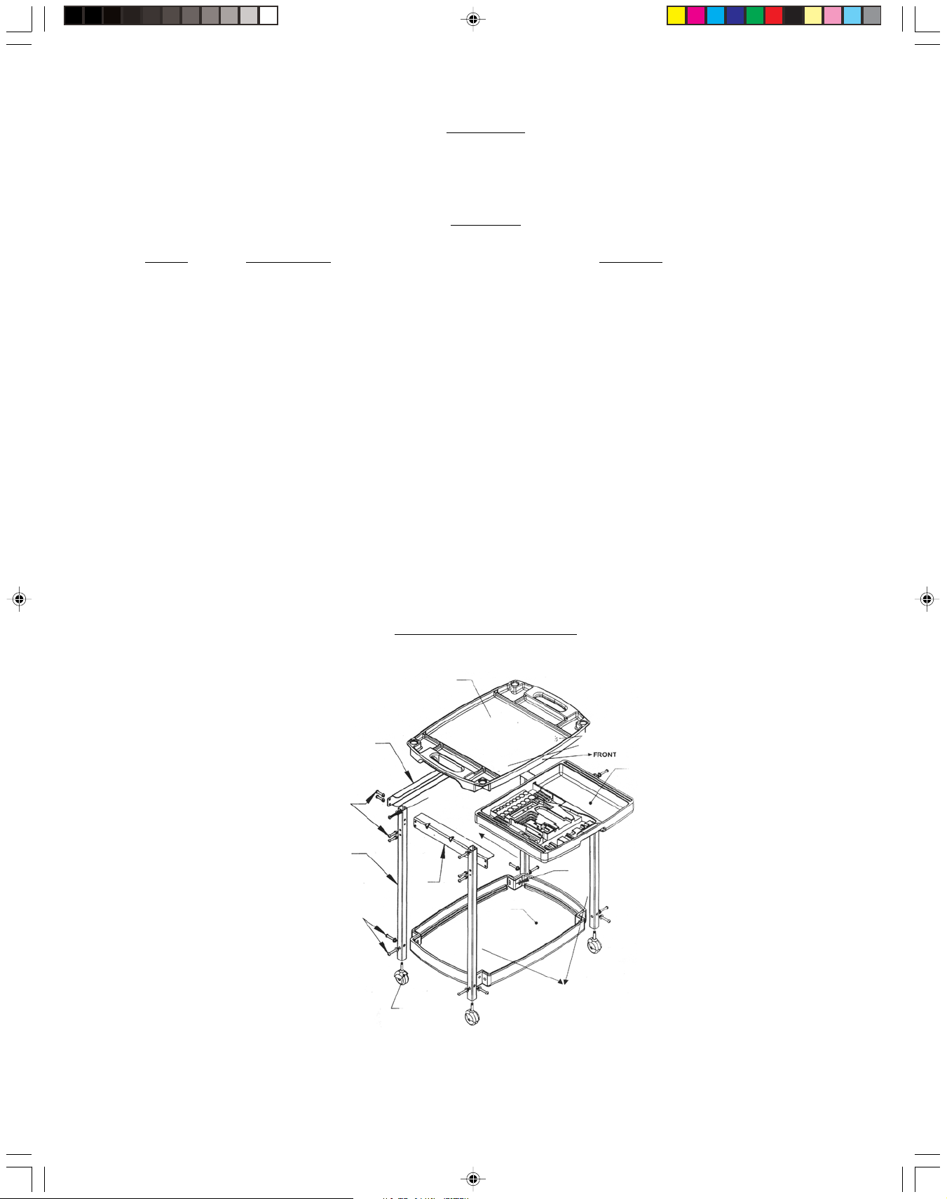
described in the Parts List and Assembly Diagram located at the end of this manual.
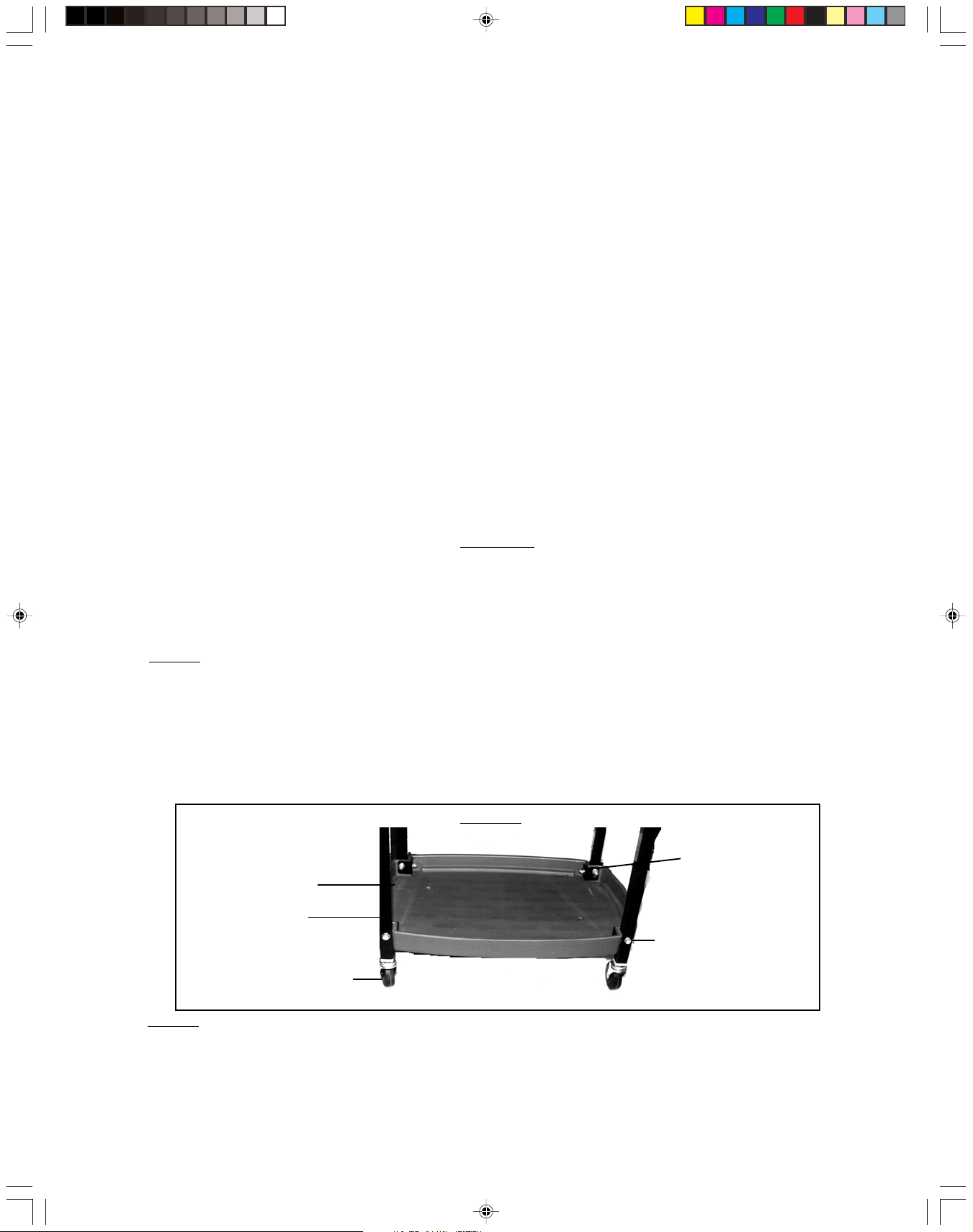
Step 1) Attach the Bottom Shelf (#4) to one of the four (4) Vertical Support Columns (#11).
Place one Vertical Support Bracket (#6) onto the inside corner of the Bottom
Shelf (#4)-see Figure 1. Set one Vertical Support Column into the corner of the
Bottom Shelf (#4). Insert one Pan Head Machine Screw (#2) through each hole in
the bottom of the Vertical Support Column (#11), through the Bottom Shelf (#4) and
into the Vertical Support Bracket (#6)-see Figure 1. Thread on Nut. Repeat for
the remaining three (3) Vertical Support Columns (#11) and Vertical Support
Brackets (#6).
Figure 1
Vertical Support
Bottom Shelf (#4)
Bracket (#6)
Vertical Support
Column (#11)
Pan Head
Machine Screw (#2)
Caster (#9)
Step 2) At the top of the Vertical Support Columns (#11), attach one (1) Side Brace (#10) to
SKU 90722 Page 3
90722 Tool and Service Cart.p65 9/30/03, 11:22 AM3
each of the two (2) sides. With the Side Brace (#10) facing inward, Insert one Pan
Head Machine Screw ( (#1) through each Vertical Support Column (#11) and through
the Side Brace (#10). Thread on Nut to secure-see assembly diagram and
Figure 2.
Page 4
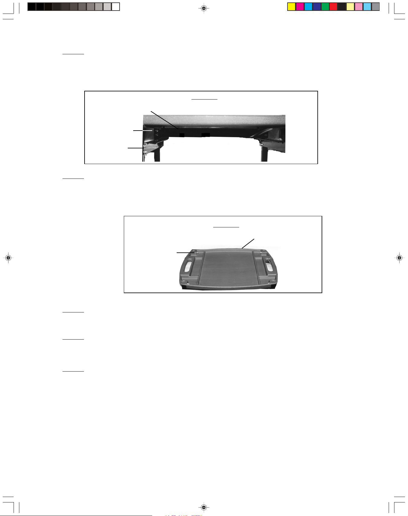
Step 3) Set the Horizontal Brace (#7) against the inside of the rear Vertical Support
Columns (#11), making certain to line up the two holes in the Horizontal Brace (#7)
with the holes in the Vertical Support Columns (#11). Insert Pan Head Machine
Screws (#1) through the Horizontal Brace (#7) and into the Vertical Support
Columns (#11). Thread on Nuts to secure in place-see Figure 2.
Figure 2
Horizontal Brace (#7)
Pan Head
Machine Screw (#1)
Side Brace (#10)
Step 4) Set the Top Shelf (#3) so that it rests on top of each of the four (4) Vertical Support
Columns (#11). Insert one Pan Head Machine Screw (#8) through the top hole in
each Vertical Support Column (#11) and into the Top Shelf (#3)-see Figure 3. Thread
on Nuts (#12) to secure in position.
Figure 3
Pan Head
Top Shelf (#3)
Machine Screw (#8)
Step 6) Each Caster (#9) has a pin on top. Insert the pin on each Caster (#9) into the bottom
of each of the four Vertical Support Columns (#11). You may need to tap the
Casters (#9) into place with a rubber mallet-see Figure 1.
Step 7) As necessary, set the tools into the Tool Drawer (#5). Slide the Tool Drawer (#5) into
place beneath the Top Shelf (#3) so that it rests on the Horizontal Brace (#11) and on
the two (2) Side Braces (#10).
Step 8) After assembly, test out the Service Cart. Roll it, making certain that the Casters roll
and swivel properly. Make sure the Tool Drawer (#5) pulls out and goes in smoothly.
Make certain that all hardware is tight. You are now ready to use the Service Cart.
CAUTION: Only use the Tool and Service Cart on a flat, level surface; never leave the cart
unattended and never use the Cart on a sloped surface.
SKU 90722
90722 Tool and Service Cart.p65 9/30/03, 11:22 AM4
Page 4
Page 5
Unpacking
When unpacking your 110 Piece Tool and Service Cart, check to make sure the following parts are
included. If any parts are missing or broken, please call HARBOR FREIGHT TOOLS at
1-800-444-3353.
Parts List
Part # Description Quantity
1 Pan Head Machine Screw-1/4” x 1-1/2” with Nut 12 sets
2 Pan Head Machine Screw-5/16” x 2” with Nut 8 sets
3 Top Shelf 1
4 Bottom Shelf 1
5 Tool Drawer 1
6 Vertical Support Bracket 4
7 Horizontal Brace 1
8 Pan Head Machine Screw- 5/16” x 1-3/4” with Nut 4 sets
9 Caster 4
10 Side Brace 2
11 Vertical Support Column 4
Note: Some parts are listed and shown for illustration purposes only and are not available
individually as replacement parts.
Assembly/Parts Diagram
3
7
5
1
8
11
6
10
2
4
SKU 90722
90722 Tool and Service Cart.p65 9/30/03, 11:22 AM5
11
9
Page 5
Page 6

TOOLS INCLUDED IN THE TOOL DRAWER
Description Quantity
Terminal 66
Drive Socket - 1/4”, carbon steel, chrome plated:
SAE 3/16”, ¼”, 5/16”, 3/8”, 7/16”
Metric: 8mm, 9mm, 10mm 8
Combination Wrench, carbon steel, polished 4
Drive Socket-3/8”, carbon steel, chrome plated 8
Extension Bar-3/8” x 3” 1
Ratchet Handle-3/8”, fully polished 1
Adapter-3/8” x ¼” 1
Nose Pliers-6”, carbon steel, polished 1
Spark Plug Socket-3/8” x 5/8” 1
Driver Plastic Disk-3/8” 1
Crimping Tool-8” with heat treated plastic handle 1
Auto Tester 1
CR-V Bit Set-1” with plastic holder 1
Hex key, carbon steel, nickel plated 4
Tire Gauge 1
Bits Driver with plastic Handle 1
Service Cart 1
THE MANUFACTURER AND/OR DISTRIBUTOR HAS PROVIDED THE PARTS DIAGRAM IN THIS MANUAL AS A REFERENCE
TOOL ONLY. NEITHER THE MANUFACTURER NOR DISTRIBUTOR MAKES ANY REPRESENTATION OR WARRANTY OF
ANY KIND TO THE BUYER THAT HE OR SHE IS QUALIFIED TO MAKE ANY REPAIRS TO THE PRODUCT OR THAT HE OR SHE
IS QUALIFIED TO REPLACE ANY PARTS OF THE PRODUCT. IN FACT, THE MANUFACTURER AND/OR DISTRIBUTOR
EXPRESSLY STATES THAT ALL REPAIRS AND PARTS REPLACEMENTS SHOULD BE UNDERTAKEN BY CERTIFIED AND
LICENSED TECHNICIANS AND NOT BY THE BUYER. THE BUYER ASSUMES ALL RISK AND LIABILITY ARISING OUT OF HIS
OR HER REPAIRS TO THE ORIGINAL PRODUCT OR REPLACEMENT PARTS THERETO, OR ARISING OUT OF HIS OR HER
INSTALLATION OF REPLACEMENT PARTS THERETO.
SKU 90722 Page 6
90722 Tool and Service Cart.p65 9/30/03, 11:22 AM6
PLEASE READ THE FOLLOWING CAREFULLY
 Loading...