

Page 1
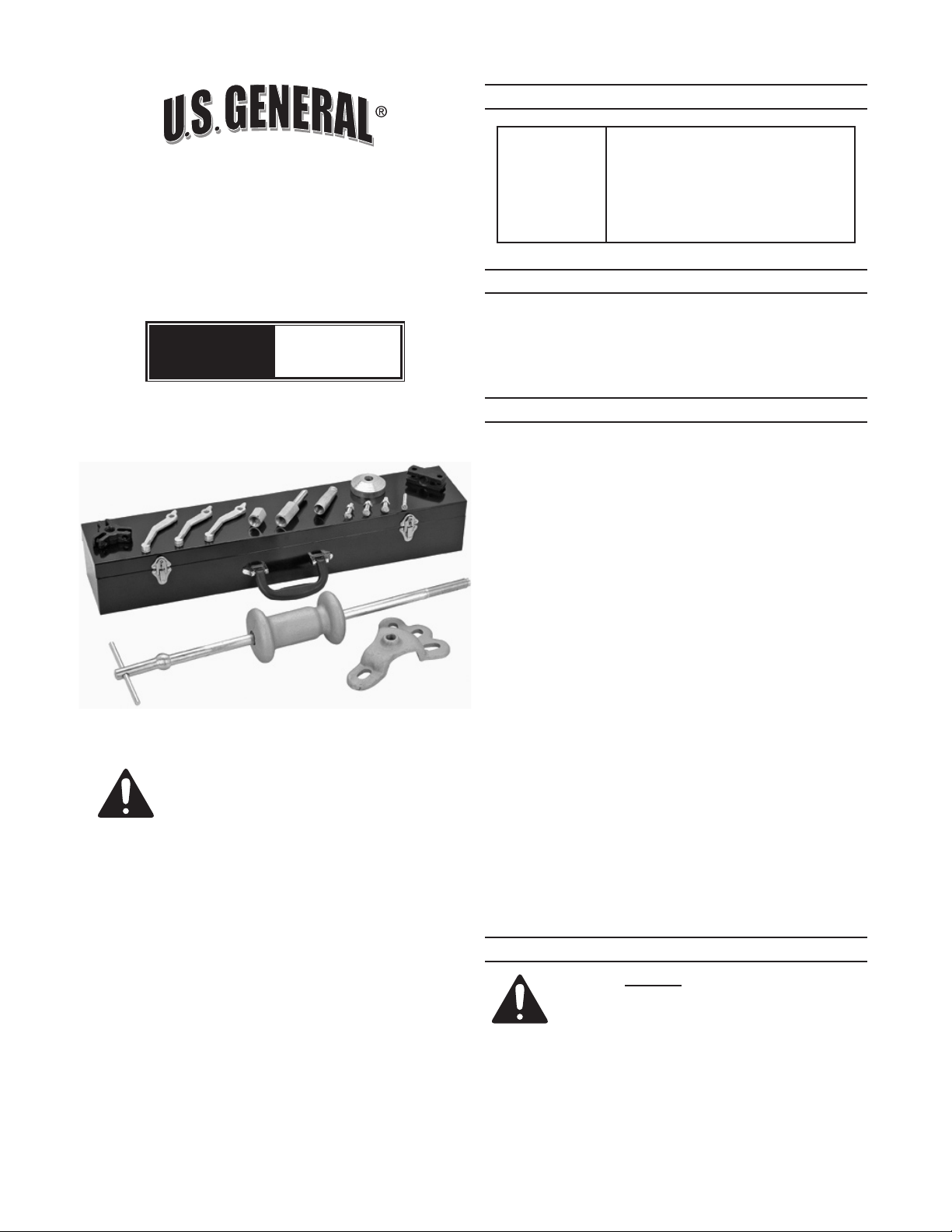
17-PIECE
HEAVY DUTY SLIDE
Functions (8):
SPECIFICATIONS
Internal or external 3-jaw puller
Internal or external 2-jaw puller
Puller hook
Rear axle puller
Dent puller
Threaded Puller/Wrench Adapter
HAMMER KIT
Model
INSTRUCTIONS AND
PRECAUTIONS
Visit our website at: http://www.harborfreight.com
SAVE THESE
INSTRUCTIONS.
READ ALL
PRECAUTIONS AND
INSTRUCTIONS.
5223
UNPACKING
When unpacking, make sure that the item is
intact and undamaged. If any parts are missing or
broken, please call Harbor Freight Tools at
1-800-444-3353 as soon as possible.
IMPORTANT SAFETY INFORMATION
Wear ANSI-approved safety goggles and heavy-1.
duty work gloves during assembly and use.
Inspect before every use; do not use if parts are 2.
damaged.
Do not use for aircraft purposes; use as intended 3.
only.
Do not modify Slide Hammer to perform a task 4.
other than what it was designed for.
Read vehicle owner’s manual and instruction 5.
manual for Jack (not included) for proper jacking
positions (where applicable) before use.
Assemble only according to instructions. 6.
Improper assembly can create hazards.
This product is not a toy. Do not allow children to 7.
play with or near this item.
Maintain product labels and nameplates. These 8.
carry important safety information. If unreadable
or missing, contact Harbor Freight Tools for a
replacement.
Harbor Freight Tools is not responsible for 9.
cosmetic damages to vehicle’s appearance due
to improper use or lack of experience for using
this type of tool.
Copyright© 2009 by Harbor Freight Tools®. All rights
reserved. No portion of this document or any artwork
contained herein may be reproduced in any shape or form
without the express written consent of Harbor Freight
Tools. Diagrams within this document may not be drawn
proportionally. Due to continuing improvements, actual
product may differ slightly from the product described herein.
Tools required for assembly and service may not be included.
For technical questions or replacement parts,
please call 1-800-444-3353.
ASSEMBLY INSTRUCTIONS
Read the ENTIRE IMPORTANT SAFETY
INFORMATION section at the beginning
of this document including all text under
subheadings therein before set up or use
of this product.
Page 2
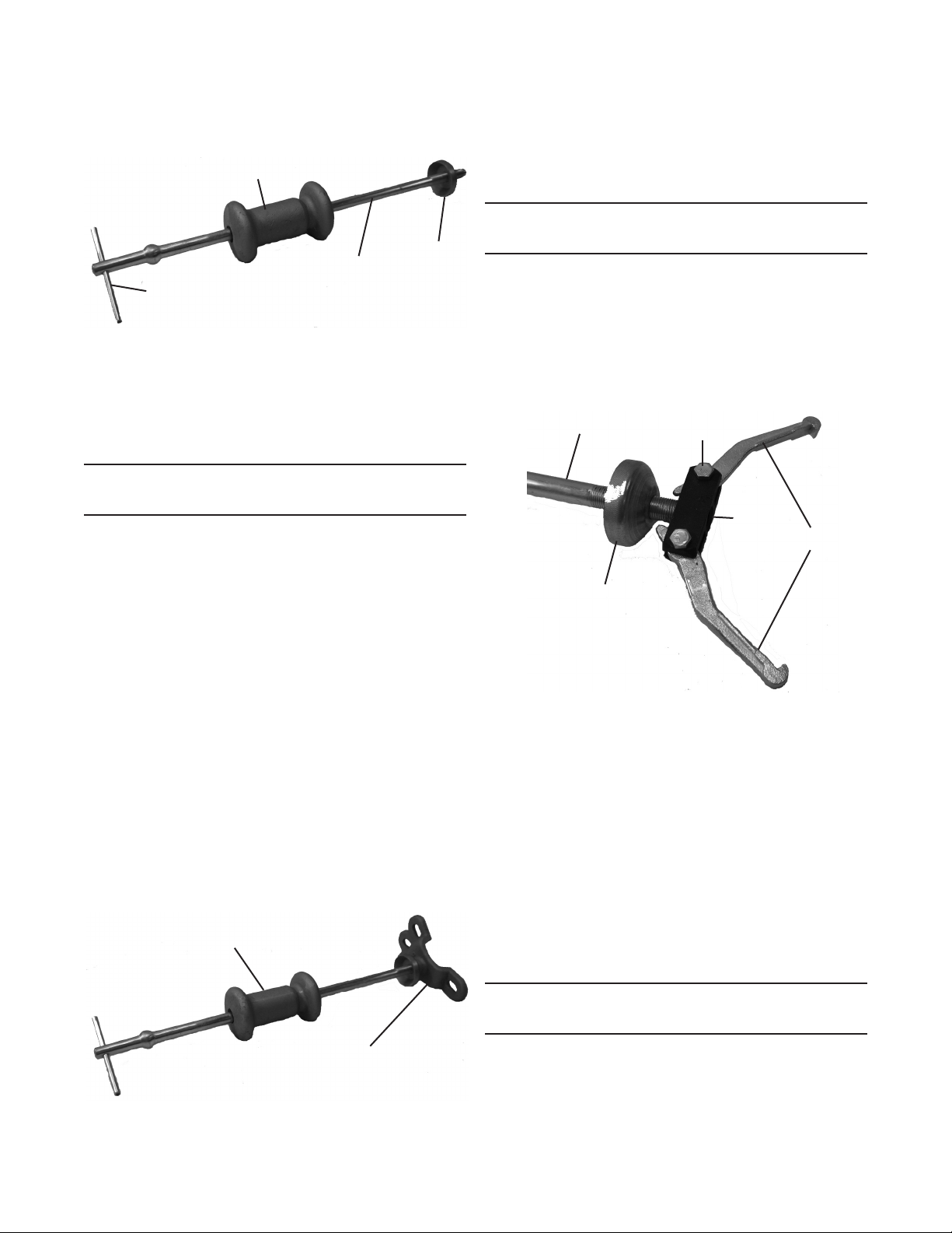
Slide the plane end of the Slide Hammer (12) 1.
onto Spindle (11). See Figure 1. Insert Cross
Bar (9) into eyelet at the end of the Spindle.
Slide Hammer (12)
Cross Bar (9)
Spindle
(11)
Lock Nut
(3)
Figure 1
Note: 2. The Lock Nut serves as a Hammer Stop
for the forward motion of the Slide Hammer (12)
and should be assembled prior to every task that
requires a pulling attachments. See Figure 1.
PULLING OPERATION
(HUB/AXLE/DRUM)
Thread hollow end of Lock Nut (3) onto Spindle.1.
Jack up the vehicle according to your vehicle’s 2.
Owner’s Manual. Make sure the car is safely
supported by Jack Stands (not included).
Remove the wheel and tire and any nuts, bolts or 3.
accessories (such a brake calipers) that may get
in the way of removing the Hub/Axle/Drum.
Bolt the Rear Axle Puller (2) onto the Hub/Axle/4.
Drum using the original lug nuts. If your vehicle
has a four-bolt Hub, match the Rear Axle Puller
to two axle bolts. If it has a ve-bolt Hub, match
to three axle bolts. Tighten the lug nuts.
Remove the Spindle (11), Handle Cross Bar (9), 5.
Lock Nut and Slide Hammer from the carrying
case. Assemble according to Figure 1.
Thread the Spindle into the Rear Axle Puller hub 6.
until its non-threaded end exits the hub. Turn
the Lock Nut (3) forward until it seats against the
Rear Axle Puller hub and hand tighten.
Slide Hammer
(12)
Rear Axle Puller (2)
Figure 2
Push the Slide Hammer towards the vehicle. 7.
Forcefully pull the Slide Hammer toward the
Handle end of the Slide Screw.
Repeat Step 6 until the Hub/Axle/Drum comes 8.
off.
JAW OPERATION OR EXTRACTION
(EXTERNAL GRIP)
Attach the hollow end of the Lock Nut (3) onto 1.
the Spindle.
Depending on the application or requirement, use 2.
the Screws and Nuts to attach the Jaws to the
2 or 3 Jaw Puller Adapters (6 or 10). Thread the
adapter onto the Spindle until non-threaded end
of the Spindle exits the Adapter.
Spindle (11)
Screw
and Nut (1)
2-Jaw
Puller
Adapter
(6)
Jaws (4)
Lock Nut
(3)
Figure 3
To grip the work piece externally, claws of the 3.
Jaws should be facing inward, as shown in
Figures 3 and 4.
Clamp the Jaws onto the object to be pulled. 4.
Turn Lock Nut (3) clockwise against the end of
the Jaws, forcing them apart, causing the claws
to be pushed inward against the work piece.
Tighten the Screws and Nuts rmly.
Push the Slide Hammer towards the work-piece, 5.
and then forcefully pull it back towards the cross
par end. Repeat as needed, and adjust the
required force based on job requirement or your
physical ability.
JAW OPERATION OR EXTRACTION
(INTERNAL GRIP)
Attach the conic end of the Lock Nut (3) onto the 1.
Spindle.
Depending on the application or requirement, use 2.
the Screws and Nuts to attach the Jaws to the
Page 2 For technical questions, please call 1-800-444-3353. SKU 5223
Page 3
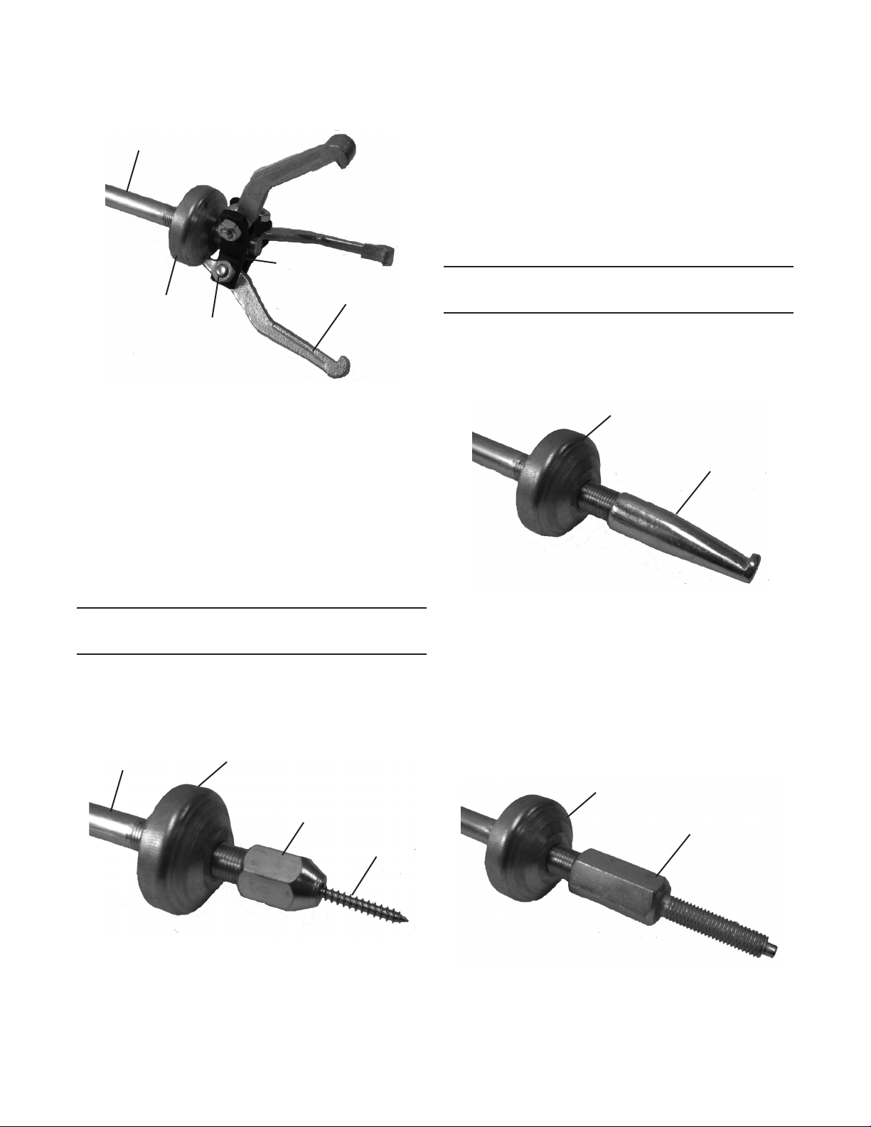
2 or 3 Jaw Puller Adapters (6 or 10). Thread the
adapter onto the Spindle until non-threaded end
of the Spindle exits the Adapter.
Spindle (11)
Lock Nut
(3)
Figure 4
Screw
and Nut (1)
3-Jaw
Puller
Adapter
(10)
Jaws (4)
To grip the work piece internally, claws of the 3.
Jaws should be facing outward.
Back-off the Lock Nut (3) to permit the jaws to 4.
be attached to the workpiece. Turn the Lock Not
forward, causing the claws to expand and grip
the work piece rmly. Tighten the fasteners.
Push the Slide Hammer towards the work-piece, 5.
and then forcefully pull it back towards the cross
par end. Repeat as needed, and adjust the
required force based on job requirement or your
physical ability.
Thread the Spindle into the Dent Puller Adapter. 5.
Thread the Lock Nut (3) against the Dent Puller
Adapter and hand tighten. See Figure 5.
Push the Slide Hammer toward the object to be 6.
pulled. Gently pull the Slide Hammer toward the
Handle Cross Bar.
CAUTION!7. Do not use excessive force when
pulling dents. Sheet metal can easily bend.
Repeat Step 5 until dent has been pulled out.8.
OPERATION
(HOOK/THREAD PULLING)
Identify the lip area you will be inserting the Pull 1.
Hook (5) into or onto.
Thread the Puller Hook onto the end of the Slide 2.
Screw. See Figure 6.
Figure 6
Lock Nut
(3)
Puller Hook (5)
OPERATION
(DENT PULLING)
Attach hollow end of the Lock Nut onto Spindle. 1.
Drill a 1/8” hole into the center of the dent.2.
Place the Self-Threading Screw (13) through the 3.
Dent Puller Adapter (7). See Figure 5.
Spindle (11)
Thread the Self-Threading Screw into the drilled 4.
hole using a #2 Phillips screwdriver.
Lock Nut
(3)
Dent Pull
Adapter (7)
Figure 5
Self-Threading
Screw (13)
Place the Puller Hook tip onto the edge of the lip 3.
of object to be pulled.
Push the Slide Hammer toward the object to be 4.
pulled. Gently pull the Slide Hammer toward the
Handle Cross Bar.
Repeat Step 4 until object has been pulled out.5.
The Screw Adapter (8) can be used for larger 6.
cross sections, heavier sheet metal, and
concentrated deep dents. See Figure 7.
Lock Nut
(3)
Screw Adapter (8)
Figure 7
Follow the Steps 1-5 until threaded object has 7.
been pulled out.
Page 3For technical questions, please call 1-800-444-3353.SKU 5223
Page 4
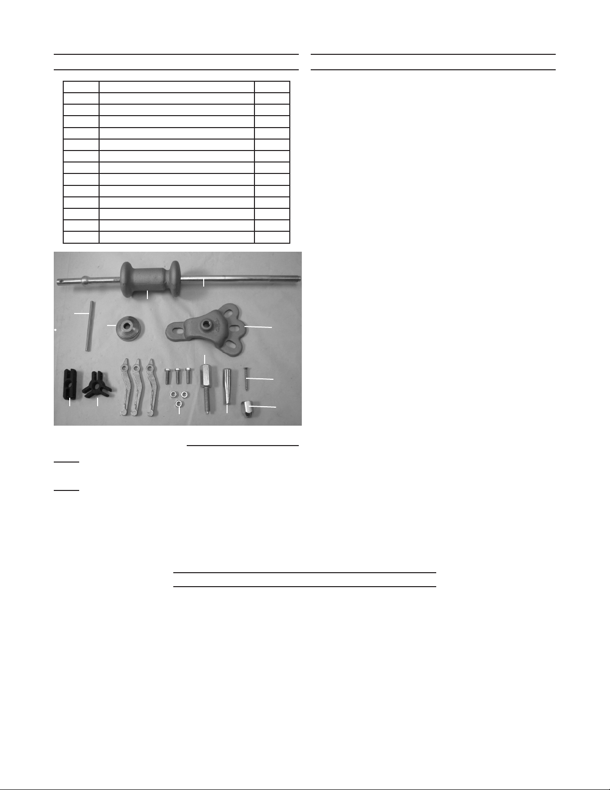
PARTS LIST & ASSEMBLY DIAGRAM
Part Description Qty.
1 Screw and Nut Set (M8 x 1.25) 3
2 Rear Axle Puller 1
3 Lock Nut 1
4 Jaw 3
5 Puller Hook 1
6 2-Jaw Puller Adapter 1
7 Dent Puller Adapter 1
8 Screw Adapter (M12 x 1.75) 1
9 Handle Cross Bar 1
10 3-Jaw Puller Adapter 1
11 Spindle 1
12 Slide Hammer 1
13 Self-Threading Screw 1
9
3
12
4
6
10
Record Serial Number Here:
Note: If product has no serial number, record month
and year of purchase instead.
Note: Some parts are listed and shown for illustration
purposes only, and are not available individually
as replacement parts.
11
2
8
13
7
1
5
LIMITED 90 DAY WARRANTY
Harbor Freight Tools Co. makes every effort to
assure that its products meet high quality and durability
standards, and warrants to the original purchaser that this
product is free from defects in materials and workmanship
for the period of 90 days from the date of purchase.
This warranty does not apply to damage due directly or
indirectly, to misuse, abuse, negligence or accidents,
repairs or alterations outside our facilities, criminal
activity, improper installation, normal wear and tear, or
to lack of maintenance. We shall in no event be liable for
death, injuries to persons or property, or for incidental,
contingent, special or consequential damages arising
from the use of our product. Some states do not allow
the exclusion or limitation of incidental or consequential
damages, so the above limitation of exclusion may
not apply to you. THIS WARRANTY IS EXPRESSLY
IN LIEU OF ALL OTHER WARRANTIES, EXPRESS
OR IMPLIED, INCLUDING THE WARRANTIES OF
MERCHANTABILITY AND FITNESS.
To take advantage of this warranty, the product or
part must be returned to us with transportation charges
prepaid. Proof of purchase date and an explanation of
the complaint must accompany the merchandise. If our
inspection veries the defect, we will either repair or
replace the product at our election or we may elect to
refund the purchase price if we cannot readily and quickly
provide you with a replacement. We will return repaired
products at our expense, but if we determine there is no
defect, or that the defect resulted from causes not within
the scope of our warranty, then you must bear the cost
of returning the product.
This warranty gives you specic legal rights and
you may also have other rights which vary from state to
state.
3491 Mission Oaks Blvd. • PO Box 6009 •
Camarillo, CA 93011 • (800) 444-3353
PLEASE READ THE FOLLOWING CAREFULLY
THE MANUFACTURER AND/OR DISTRIBUTOR HAS PROVIDED THE PARTS LIST AND ASSEMBLY DIAGRAM IN THIS DOCUMENT AS
A REFERENCE TOOL ONLY. NEITHER THE MANUFACTURER OR DISTRIBUTOR MAKES ANY REPRESENTATION OR WARRANTY
OF ANY KIND TO THE BUYER THAT HE OR SHE IS QUALIFIED TO MAKE ANY REPAIRS TO THE PRODUCT, OR THAT HE OR SHE
IS QUALIFIED TO REPLACE ANY PARTS OF THE PRODUCT. IN FACT, THE MANUFACTURER AND/OR DISTRIBUTOR EXPRESSLY
STATES THAT ALL REPAIRS AND PARTS REPLACEMENTS SHOULD BE UNDERTAKEN BY CERTIFIED AND LICENSED TECHNICIANS,
AND NOT BY THE BUYER. THE BUYER ASSUMES ALL RISK AND LIABILITY ARISING OUT OF HIS OR HER REPAIRS TO THE
ORIGINAL PRODUCT OR REPLACEMENT PARTS THERETO, OR ARISING OUT OF HIS OR HER INSTALLATION OF REPLACEMENT
PARTS THERETO.
Page 4 For technical questions, please call 1-800-444-3353. SKU 5223
 Loading...