

Page 1
PRODUCT #13535 INSTRUCTION SHEET
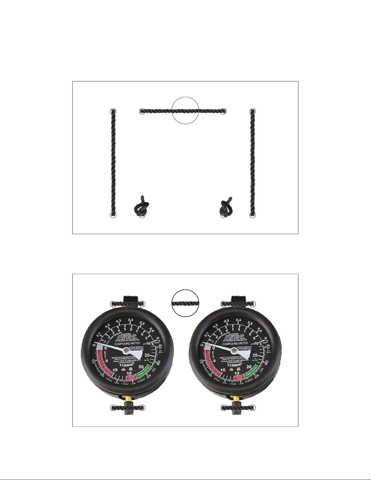
Your #13535 Carb Synchronizer Kit comes with a gauge mounting board. To mount gauges simply thread
small bungee supplied through board as shown in photo below. e knots at ends as shown.
Turn board over and li bungee to slide gauges into place. See Photo Below.
Page 2
BRP-Rotax
AE_912_0083
1
2
1
MAINTENANCE MANUAL LINE
FUEL SYSTEM
CARBURETOR SYNCHRONIZATION
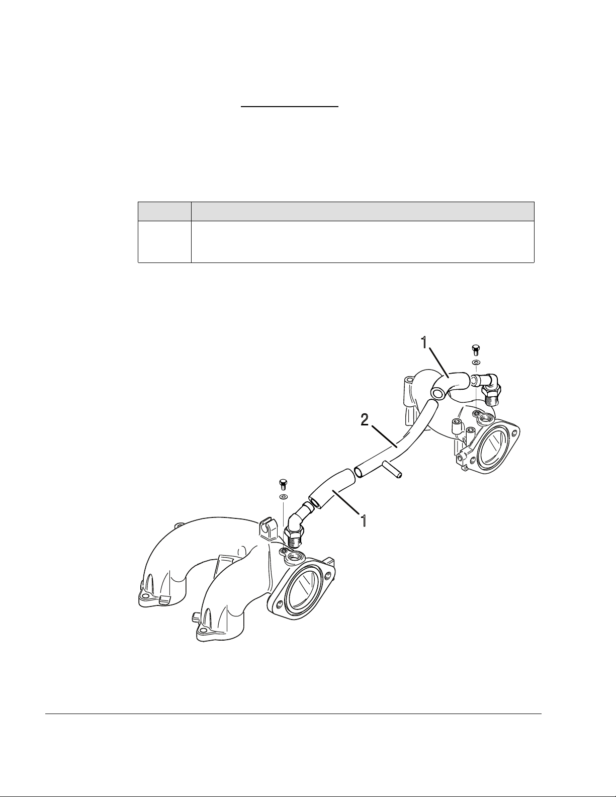
Idle speed Checking the synchronization at idle speed
For smooth idling, synchronization of the throttle valves is necessary. When synchronizing, slacken both bowden cables (throttle lever lies close on the adjustment screw).
Instruction To synchronize when idling the following steps are necessary.
Step
1 Detach the resonator hose of the compensating tube to separate the two air
NOTE
First carry out the mechanical synchronization and then the pneumatic synchronization (if required).
Procedure
intake systems. In this condition, a slight difference in the engine running
should be noticeable.
12–20–00
Page 26
Ed. 04 / July 01 2021
Figure 7.15: Synchronization at idle speed
1 Resonator hose 2
Compensating tube
Effectivity: 912 Series
Rev. 1
Page 3

MAINTENANCE MANUAL LINE
MECHANICAL SYNCHRONIZATION
General note
Non-compliance can result in serious injuries or death!
Always observe the engine from a safe place while it is running. Check that the cockpit
BRP-Rotax
m WARNING
is occupied by a competent operator.
Basic throttle
adjustment
For synchronous basic throttle adjustment proceed as follows.
Step
1 Remove cable fixation (4) on throttle lever (1).
2
3 Unscrew idle speed adjustment screw (2) until it is free of the stop.
4
5
6
7
8
Procedure
Return the throttle lever (1) to its idle stop position (3) by hand. There
should be no resistance during this procedure.
Insert a 0.1 mm (0.004 in.) feeler gauge (gap X) between the idle speed adjustment screw (2) and the carburetor idle stop (3) , then gently turn the idle
screw clockwise until contact is made with the 0.1 mm (0.004 in.) feeler
gauge.
Pull out the feeler gauge and then turn each idle speed adjustment screw
(2) 1.5 turns clockwise.
Gently turn each idle mixture screw (6) (clockwise) until it is fully inserted
and then reopen by 1.5 turns counter clockwise.
Check that the throttle valve opens fully automatically.
Adjust the two bowden cables for simultaneous opening of the throttle
valves.
Carry out the above procedure on both carburetors.
Synchronization You must at this point place the throttle lever in the cockpit to the idle stop position. It is an
advantage at this point to enlist the help of an assistant to ensure that the throttle lever remains in this position during the next steps of the synchronization process.
Step
1 As soon as the throttle lever in the cockpit remains is in the idle stop posi-
2
3
Effectivity: 912 Series
Rev. 1
Procedure
tion, check the throttle valve lever to the carburetor idle stop position.
Using the cable fixation, secure the bowden cable accordingly.
As soon as the two carburetor bowden cables are installed (throttle lever in
cockpit in idle position), you must check that the idle speed adjustment
screw rests fully on the idle stop without pressure.
12–20–00
Page 27
Ed. 04 / July 01 2021
Page 4

BRP-Rotax
MAINTENANCE MANUAL LINE
ATTENTION
An idle speed which is too low can result in gearbox wear, and if the idle speed is
too high, the engine is harder to start.
Step
4
Procedure
Start the engine and verify the idle speed. If the idle speed is too high or too
low, adjust accordingly with idle speed adjustment screw.
5
Check the true running of the engine. If necessary, adjust with the idle mixture screw.
Carry out the above procedure on both carburetors.
Figure 7.16: Mechanical synchronization
1 Throttle valve lever 2
Idle stop position
3
Return spring
5
Idle adjustment
7
PNEUMATIC SYNCHRONIZATION
General note
Non-compliance can result in serious injuries or death!
Always observe the engine from a safe place while it is running. Check that the cockpit
12–20–00
Page 28
Ed. 04 / July 01 2021
Adjustment screw
4 Cable fixation
6 Idle mixture screw
Plug screw M3.5x5
8
m WARNING
is occupied by a competent operator.
Effectivity: 912 Series
Rev. 1
Page 5
BRP-Rotax
AE_912_0085
2
4
3
5
1
4
3
5
MAINTENANCE MANUAL LINE
NOTE
Perform a mechanical synchronization before attempting a pneumatic
synchronization.
Special tool The two carburetors are adjusted to equal flow rate at idling with a suitable flow meter or
vacuum gauge(s).
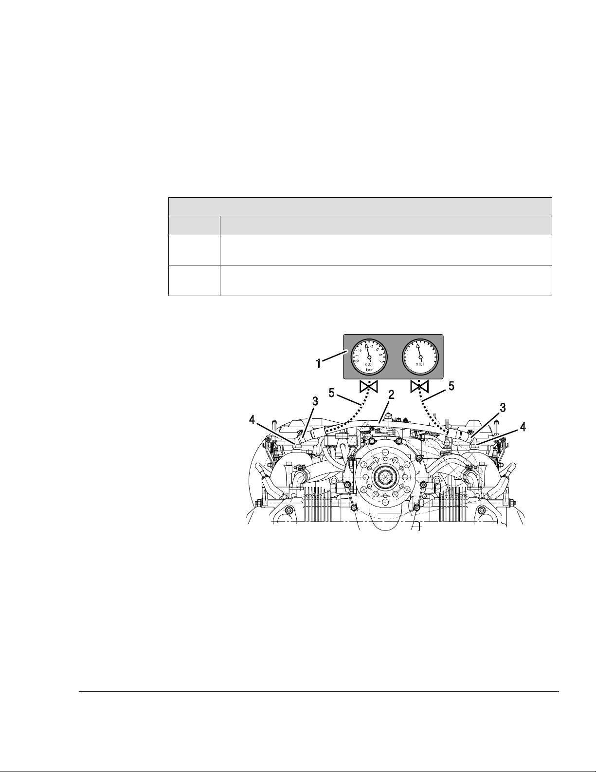
Connection Possible connection methods.
Option 1
Step
Procedure
1
2
Remove the compensating tube (2) from the push on angular tube (4) after
removing the two clamps.
Using the push on angular tube (4) and compensating tube (2) install a flexible rubber hose (5) leading to the vacuum gauge (1).
Effectivity: 912 Series
Rev. 1
Figure 7.17: Option 1
Vacuum gauge
1
Clamp
3
5 Rubber hose
Compensating tube
2
Angular tube
4
12–20–00
Page 29
Ed. 04 / July 01 2021
Page 6
BRP-Rotax
AE_912_0087
2
5
1
4
3
6
MAINTENANCE MANUAL LINE
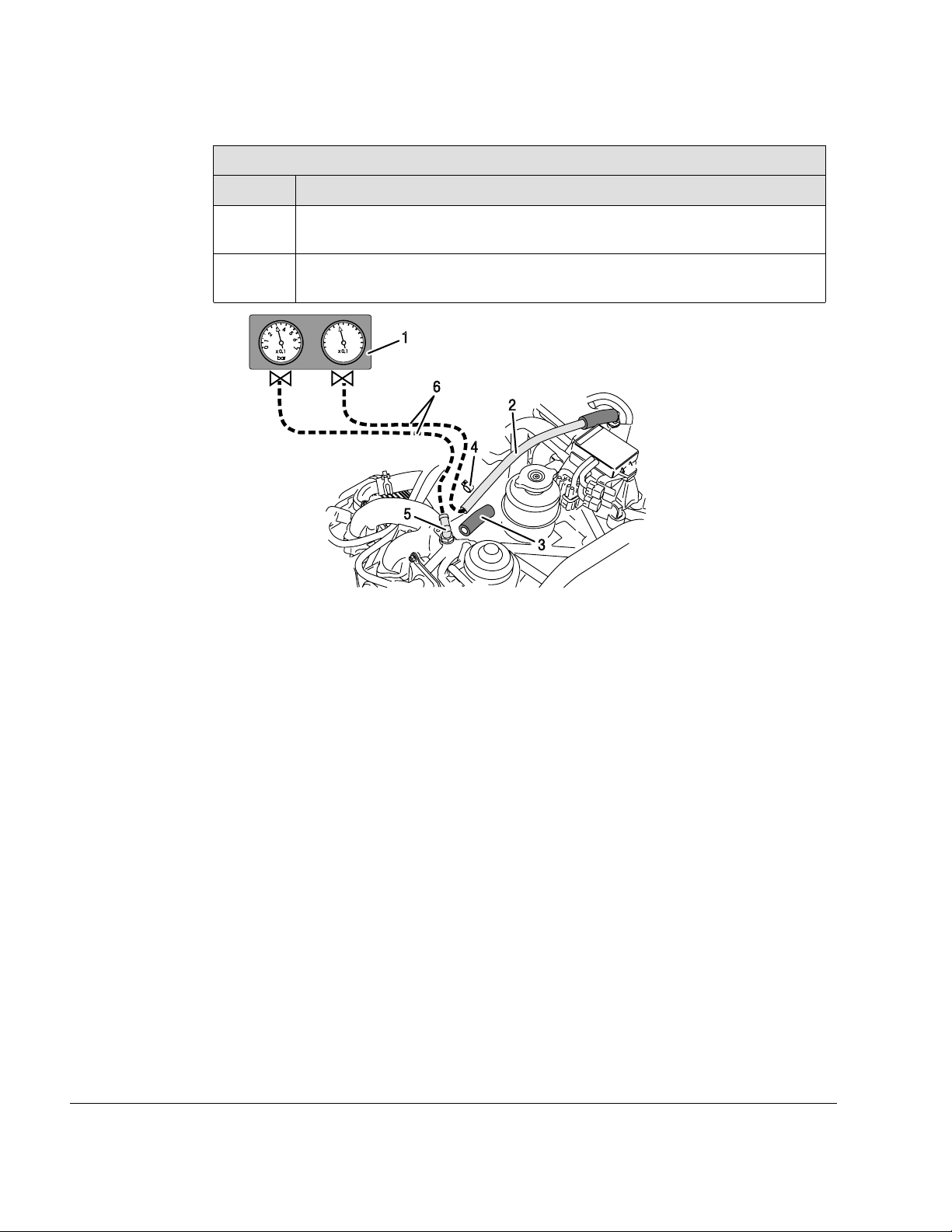
Option 2
Step
Procedure
1 Remove one end of the compensating tube (2) and tube from the push on
angular tube (5) after removing the two tension clamp (4).
2
Using the push on angular tube (5) and compensating tube (2) install a flexible rubber hose (6) leading to the vacuum gauge (1).
Figure 7.18: Option 2
12–20–00
Page 30
Ed. 04 / July 01 2021
Vacuum gauge
1
3 Tube 4
Angular tube
5
Compensating tube
2
Clamp
6 Rubber hose
Effectivity: 912 Series
Rev. 1
Page 7
BRP-Rotax
2
1
4
3
1
2
4
AE_912_0088
MAINTENANCE MANUAL LINE
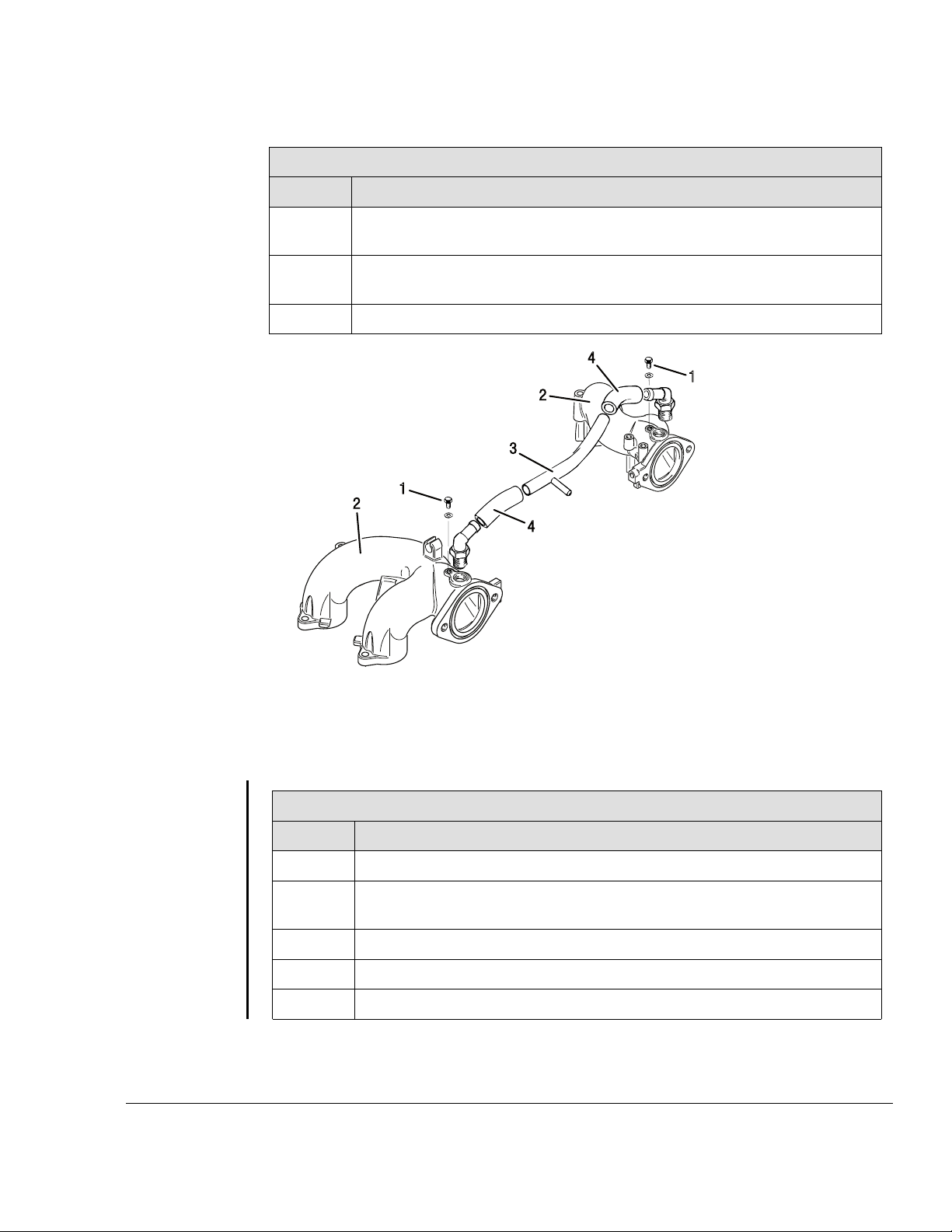
Option 3
Step
Procedure
1
2
3
Remove hex. screw M6x6 from intake manifold and connect the vacuum
gauge.
Remove the compensation hose with attached resonator hose (connection
between intake manifolds) and plug the fittings in the intake manifolds.
After synchronization, tighten the screw M6x6 with LOCTITE 243.
Figure 7.19: Option 3
1 Hex. screw M6x6 2 Intake manifold
Compensation tube
3
Option 4
Step
1 Install the vacuum gauge.
2 Clamp tube (2) with clamping pliers (1). on the cylinder 1/3 side. The com-
3
Effectivity: 912 Series
Rev. 1
4
5
Procedure
pensation tube (3) does not have to be removed.
Remove the screw (4).
Install the hose nipple M6 (5) with sealing ring (6).
After synchronization tighten the screw M6x6 with LOCTITE 243.
4 Resonator hose
12–20–00
Page 31
Ed. 04 / July 01 2021
Page 8

BRP-Rotax
MAINTENANCE MANUAL LINE
Figure 7.20: Option 4
Clamping pliers
1
Compensation tube
3
Hose nipple
5
Hose, Cylinder 1/3 side
2
4 Screw
Sealing ring
6
IDLE SPEED CHECK
General note Before proceeding, secure the aircraft on the ground using wheel chocks and ropes.
m WARNING
Non-compliance can result in serious injuries or death!
Secure the propeller region before test run watch it. Secure a safe area around propel-
ler during test run.
Start the engine and verify the idle speed. If necessary correct as per Chapter 12–20–00
section Idle speed adjustment
Setting of more than 1/2 turn
If a setting of more than 1/2 turn is required, repeat mechanical synchronization to prevent too high a load on the idle stops. If the idle speed is too high, the maximum the idle
screw can be unscrewed is complete turn.
12–20–00
Page 32
Ed. 04 / July 01 2021
Effectivity: 912 Series
Rev. 1
Page 9

BRP-Rotax
MAINTENANCE MANUAL LINE
No satisfactory
result
If an unsatisfactory result is achieved, inspect the idle jets for contamination and clean if
necessary.
ATTENTION
Also check for translucent, jelly-like contamination. Inspect for free passage.
OPERATING RANGE CHECK
General note Once the proper idling speed has been established, it is necessary to check the operating
range above the idle speed.
First establish that the engine is developing full take-off performance or take-off rpm when
selected in the cockpit. Then the setting of the operating range (idle to full throttle) can be
checked or adjusted.
Procedure To control the operating range above idling the following steps are necessary.
Step
1
Procedure
Start and warm up engine (See Operators Manual). Select full power and
check that both pressure gauges are registering the same readings. If the
same reading is not made on both gauges.
Step
Procedure
1
2 Check that carburetor actuation effects full travel and that
3
2 Once full power has been established on both carburetors, retard the throt-
tle and observe the pressure gauge settings. The pressure gauges should
show the same reading for both carburetors.
Shut down the engine.
starting carburetors (choke) are in the full off position.
If necessary, fit/modify the carburetor actuation as required to achieve full power on both carburetors.
NOTE
Discrepancies must be compensated for by adjusting the off idle
adjustment.
Step
1 Shut down the engine.
2 Loosening the locknut on the bowden cable and adjusting
3 Tightening the locknut.
4 Re-testing the engine.
Procedure
the off idle adjustment.
Effectivity: 912 Series
Rev. 1
12–20–00
Page 33
Ed. 04 / July 01 2021
Page 10

BRP-Rotax
MAINTENANCE MANUAL LINE
Step
3 Final idle speed adjustment may be required by resetting the idle speed ad-
4 Equal adjustment must be made on both carburetors.
5
Procedure
justment screws.
Any major adjustments required necessitate replaced verification of all parameters mentioned in this procedure.
12–20–00
Page 34
Ed. 04 / July 01 2021
Effectivity: 912 Series
Rev. 1
 Loading...