

Page 1
The USFT VT-X5 Install Guide
USFleetTracking
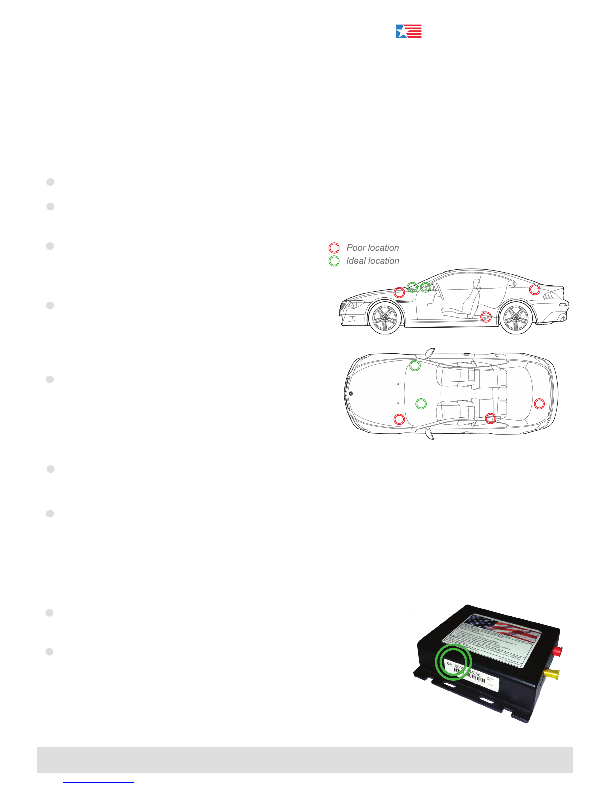
Poor location
Ideal location
Thank you for purchasing your new GPS vehicle tracking system!
Installation of your new GPS tracking device couldn’t be easier.
Just follow these simple steps.
VT-X5
Step 1 > Device Placement
Plug the two antenna cables and wiring harness into the device.
Place the antenna under the dash above the instrument cluster (reference Image A). The adhesive side of the
antenna should be facing the sky.
A good placement of the device will yield a minimum of 7
satellites. The device will not transmit data location with
less than 4 satellites in view.
Run the antenna cables along the side of the dash at
the door hinge and place the VT-X5 under the dash. For
best results, use a zip-tie to secure the device to ensure
it doesn’t fall from beneath the dash.
Our device transmits once every 30 minutes if sitting
still, or once every 5 or 10 seconds (depending on your
rate plan) when the vehicle is moving faster than 4 mph.
Driving the vehicle around the block will assist in its rst
data transmission.
The best location has a full view of the sky through the front windshield (reference Image A.) Make sure the
device is kept free from direct exposure to the elements (sun, heat, rain, moisture).
When installed inside a building, your unit may not receive a GPS signal or cellular signal. GPS signals WILL
penetrate glass, plastic, foam, berglass, and wood. GPS signals will NOT penetrate metal.
Image A
Step 2 > Wiring and Installation
Please verify that your device is activated prior to installation. When
activating a unit, refer to the SN# on the side of the device (see Image B).
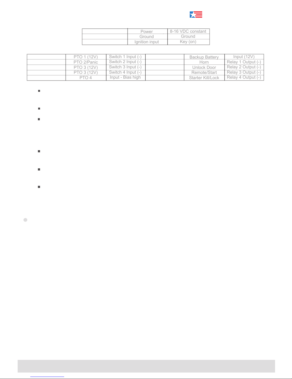
The VT-X5 requires a standard 3-wire installation to operate effectively.
Please familiarize yourself with the 3 wires required for functionality as well
as the optional wires associated with added available features. The wire
colors and functions are on the back side of this installation guide.
NOTE: Do not cut wiring harness to shorten length of cable as this will void warranty.
405.726.9900 | 2912 NW 156th Street | Edmond, Oklahoma 73013 | usft.com
Install
Image B
Page 2
The USFT VT-X5 Install Guide
USFleetTracking
Power
Ground
Ignition input
8-16 VDC constant
Ground
Key (on)
PTO 1 (12V)
PTO 2/Panic
PTO 3 (12V)
PTO 3 (12V)
PTO 4
Switch 1 Input (-)
Switch 2 Input (-)
Switch 3 Input (-)
Switch 4 Input (-)
Input - Bias high
Backup Battery
Horn
Unlock Door
Remote/Start
Starter Kill/Lock
Input (12V)
Relay 1 Output (-)
Relay 2 Output (-)
Relay 3 Output (-)
Relay 4 Output (-)
Long Red wire
*
Long Black wire
*
Long White wire
*
* Must be connected for device to work properly.
Green/Yellow wire
White wire
Blue wire
Red/White wire
Grey wire
The long red wire (power) should be directly wired to a constant 8V - 16V power source found at the
key source or fuse panel.
The long black wire (ground) should be securely fastened to a grounded screw or to chasis ground.
The long white wire (ignition) is the ignition event wire that is best installed directly to the ignition
wire. Ensure that power to the ignition wire is available ONLY when the vehicle ignition is turned on.
All makes and models of vehicles are different - we recommend you make sure that you know your
particular vehicle’s Constant and Ignition wires and their specic color(s) prior to installation.
The white, blue, red/white, grey and green/yellow wires (input) can be used to monitor many
functions such as PTO activity (Power Take Off), emergency lights, panic switch, etc.
The green, white/brown, yellow and orange wires (output) can be used to lock/unlock doors, honk
horn, remote start or disable starter, etc.
The red bundle wires are to be connected to a 12V backup battery.
Red bundle
White/Brown wire
Yellow wire
Green wire
Orange wire
Step 3 > Status LED Lights
Blinking LED lights will signal the following:
■ 1 blink - the modem is not detecting a SIM card.
■ 2 blinks - the modem is not detecting a cellular signal. Check antenna connection.
■ 3 blinks - the GPS receiver is not tracking any satellites. Check antenna connection and placement.
■ 4 blinks - the modem has no cellular signal and GPS is not tracking any satellites.
■ 5 blinks - the modem is not detecting a SIM card and GPS is not tracking any satellites.
■ 6 blinks - the modem is not responding, and the antenna may be disconnected or the device may
be incorrectly congured within the rmware.
■ 7 blinks - the modem is not responding and the antenna may be disconnected and GPS is not
tracking any satellites.
■ 8 blinks - GPS is okay, but the modem is not registered on a network. A problem with the cellular
account is possible.
■ 9 blinks - the modem is working correctly, and GPS is tracking satellites but is not making position
xes. The device or antenna may need repositioning for a good view of the sky.
If you have any questions or encounter any difculties with this system, please contact our technical support.
Monday through Friday 7 a.m. to 7 p.m. CST and Saturday 9 a.m. to 4 p.m. CST
Installation and Wiring
405.726.9900 | 2912 NW 156th Street | Edmond, Oklahoma 73013 | usft.com
VT-X5
 Loading...