

Page 1

Test Equipment Depot - 800.517.8431 - 99 Washington Street Melrose, MA 02176 - TestEquipmentDepot.com
Keysight V3500A
Handheld RF Power Meter
User’s Guide
Page 2

Page 3

Page 4

Notices
CAUTION
WARNING
© Keysight Technologies, 2010 – 2014
No p art o f this manu al may be re produce d in
any form or by any means (including electronic storage and retrieval or translation
into a foreign language) without prior agreement and written consent from Keysight
Technologies as governed by United States
and international copyright laws.
Manual Part Number
V3500-90001
Edition
Edition 7, December 12, 2014
Keysight Technologies
1400 Fountaingrove Parkway
Santa Rosa, CA 95403
Trademark Acknowledgements
Microsoft, Visual Studio, and Windows are
U.S. registered trademark of Microsoft
Corporation.
Pentium is a U.S. registered trademark of
Intel Corporation.
Warranty
The material contained in this document is provided “as is,” and is subject to being changed, without notice,
in future editions. Further, to the maximum extent permitted by applicable
law, Keysight disclaims all warranties, either express or implied, with
regard to this manual and any information contained herein, including
but not limited to the implied warranties of merchantability and fitness for
a particular purpose. Keysight shall
not be liable for errors or for incidental or consequential damages in connection with the furnishing, use, or
performance of this document or of
any information contained herein.
Should Keysight and the user have a
separate written agreement with
warranty terms covering the material
in this document that conflict with
these terms, the warranty terms in the
separate agreement shall control.
Technology Licenses
The hardware and or software described in
this document are furnished under a license
and may be used or copied only in accordance with the terms of such license.
Restricted Rights Legend
U.S. Government Restricted Rights. Software and technical data rights granted to
the federal government include only those
rights customarily provided to end user customers. Keysight provides this customary
commercial license in Software and technical data pursuant to FAR 12.211 (Technical
Data) and 12.212 (Computer Software) and,
for the Department of Defense, DFARS
252.227-7015 (Technical Data - Commercial
Items) and DFARS 227.7202-3 (Rights in
Commercial Computer Software or Computer Software Documentation).
Safety Notices
A CAUTION notice denotes a hazard. It calls attention to an operating procedure, practice, or the like
that, if not correctly performed or
adhered to, could result in damage
to the product or loss of important
data. Do not proceed beyond a
CAUTION notice until the indicated
conditions are fully understood and
met.
A WARNING notice denotes a
hazard. It calls attention to an
operating procedure, practice, or
the like that, if not correctly performed or adhered to, could result
in personal injury or death. Do not
proceed beyond a WARNING
notice until the indicated conditions are fully understood and
met.
II V3500A User’s Guide
Page 5
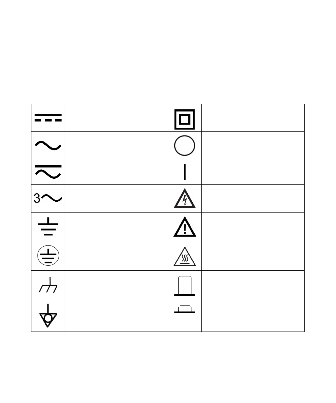
Safety Symbols
Direct current (DC)
Alternating current (AC)
The following symbols on the instrument and in the documentation
indicate precautions which must be taken to maintain safe operation of
the instrument.
Equipment protected throughout by
double insulation or reinforced
insulation
Off (supply)
Both direct and alternating current
Three-phase alternating current
Earth (ground) terminal
Protective conductor terminal
Frame or chassis terminal Out position of a bi-stable push control
Equipotentiality In position of a bi-stable push control
On (supply)
Caution, risk of electric shock
Caution, risk of danger (refer to this manual
for specific Warning or Caution information)
Caution, hot surface
V3500A User’s Guide III
Page 6

General Safety Information
WARNING
CAUTION
The following general safety precautions must be observed during all
phases of operation, service, and repair of this instrument. Failure to
comply with these precautions or with specific warnings elsewhere in this
manual violates safety standards of design, manufacture, and intended
use of the instrument. Keysight Technologies assumes no liability for the
customer’s failure to comply with these requirements.
• Observe all markings on the instrument before connecting any wiring
to the instrument.
• Do not operate the instrument in an explosive atmosphere or in the
presence of flammable gases or fumes.
• Do not service or perform adjustments alone. Under certain condition,
hazardous voltages may exist, even with the equipment switched off.
To avoid dangerous electric shock, service personnel must not
attempt internal service or adjustment unless another person,
capable of rendering resuscitation or first aid, is present.
• Do not substitute parts or modify equipment to avoid the danger of
introducing additional hazards. Return the instrument to Keysight
Sales Office for service and repair to ensure the safety features are
maintained.
• Do not operate damaged equipment as the safety protection features
built into this instrument may have been impaired, either through
physical damage, excessive moisture, or any other reason. Remove
power and do not use the instrument until safe operation can be
verified by service-trained personnel. If necessary, return the
instrument to Keysight Technologies Sales and Service Office for
service and repair to ensure the safety features are maintained.
IV V3500A User’s Guide
• Ensure proper insertion of battery in the power meter, and follow the
correct polarity.
Page 7

Environmental Conditions
CAUTION
This instrument is designed for indoor use and in an area with low
condensation with use of standard or compatible test probes. The table
below shows the general environment requirements for this instrument.
Environment conditions Requirements
Operating environment 0°C to 50°C
Operating relative humidity 80% RH for temperature up to 35 °C,
Storage environment –10 °C to 70 °C
Altitude Up to 2000 meters
Pollution degree Pollution Degree 2
• The Keysight V3500A complies with the following safety and EMC
• Degradation of some instrument specifications can occur in the presence of
non-condensing
requirements:
• IEC 61326-2-1:2005/ EN 61326-2-1:2006
• Canada: ICES-001:2004
• Australia/New Zealand: AS/NZS CISPR11: 2004
ambient electromagnetic (EM) fields and noise that are coupled to the
powerline or I/O cables of the instrument. The instrument will self-recover and
operate to all specifications when the source of ambient EM field and noise are
removed or when the instrument is protected from the ambient EM field or
when the instrument cabling is shielded from the ambient EM noise.
V3500A User’s Guide V
Page 8

Regulatory Markings
The CE mark is a registered trademark
of the European Community. This CE
mark shows that the product complies
with all the relevant European Legal
Directives.
The C-tick mark is a registered
trademark of the Spectrum
Management Agency of Australia. This
signifies compliance with
the Australia EMC Framework
regulations under the terms of the
Radio Communication Act of 1992.
ICES/NMB-001 indicates that this ISM
device complies with the Canadian
ICES-001.
Cet appareil ISM est confomre a la
norme NMB-001 du Canada.
This instrument complies with the
WEEE Directive (2002/96/EC) marking
requirement. This affixed product label
indicates that you must not discard
this electrical or electronic product in
domestic household waste.
VI V3500A User’s Guide
Page 9

Waste Electrical and Electronic Equipment (WEEE) Directive
2002/96/EC
This instrument complies with the WEEE Directive (2002/96/EC) marking
requirement. This affixed product label indicates that you must not discard
this electrical or electronic product in domestic household waste.
Product Category:
With reference to the equipment types in the WEEE directive Annex 1, this
instrument is classified as a “Monitoring and Control Instrument” product.
The affixed product label is as shown below.
Do not dispose in domestic household waste
V3500A User’s Guide VII
Page 10

In This Guide…
1Getting Started
This chapter introduces the key features of the V3500A Handheld RF
Power Meter and prepares the power meter for initial setup.
2 Knowing your Instrument
This chapter specifies the characteristics, environmental conditions, and
specifications of the V3500A Handheld RF Power Meter. This chapter
contains a brief description of the instrument outlook, front panel
operation, and front panel procedure.
3 Driver Installation and Commands
This chapter provides you the step-by-step programming driver installation
procedure, remote USB operation, and basic drive commands of the
V3500A Handheld RF Power Meter.
4RF Measurement Basics
This chapter describes the RF measurement basics of the V3500A
Handheld RF Power Meter.
5 Characteristics and Specifications
This chapter describes the instrument characteristics and specifications
of the V3500A Handheld RF Power Meter.
VIII V3500A User’s Guide
Page 11

Declaration of Conformity (DoC)
NOTE
The Declaration of Conformity (DoC) for this instrument is available on the
Web site. You can search the DoC by its instrument model or description.
If you are unable to search for the respective DoC, please contact your
local Keysight representative.
V3500A User’s Guide IX
Page 12

THIS PAGE HAS BEEN INTENTIONALLY LEFT BLANK.
X V3500A User’s Guide
Page 13

Contents
1 Getting Started 1
Introduction 2
Key features 3
Initial Inspection 3
Standard purchase items 3
Optional purchase items 4
Handling Precaution 4
Setting-up your Instrument 5
Connectivity 5
Power supply 8
2 Knowing your Instrument 9
Product at a Glance 10
Product dimensions 10
The front panel keypad 11
How to navigate the menu system 13
How to power on the V3500A 16
Front panel operations 17
Measuring power 17
Zeroing the power meter 18
Setting the input frequency 18
Setting the measurement speed 19
Enabling and disabling high-speed mode 19
Saving the instrument state 20
Recalling the instrument state 20
Setting units: dBm or watts 21
Controlling the backlight 22
Setting the backlight auto-shutoff interval 22
V3500A User’s Guide XI
Page 14

Using relative offset function 23
3 Driver Installation and Commands 25
System Requirements 26
Driver Installation 27
Installing USB driver 27
Installing USB driver (Windows 7) 34
Confirming the USB driver installation 38
Uninstalling the USB driver 41
Installing programming driver 42
Instrument Address 46
Remote USB Operation 47
Introduction 47
Bus connections 47
Remote USB commands 48
Basic driver commands 49
Basic V3500A commands 55
Averaging control commands 56
Measurement speed control commands 57
Unit of measurement commands 58
Relative Offset Commands 59
Miscellaneous commands 60
Examples 61
4 RF Measurement Basics 81
Power Definition 82
Units of Measurement 84
Watts 84
Decibels 84
RF power measurement 85
Low frequency method 85
XII V3500A User’s Guide
Page 15

High frequency method 85
Power of various types of signals 87
Measurement accuracy 89
5 Characteristics and Specifications 93
Product Characteristics 94
Product Specifications 96
SWR 98
V3500A User’s Guide XIII
Page 16

THIS PAGE HAS BEEN INTENTIONALLY LEFT BLANK.
XIV V3500A User’s Guide
Page 17

List of Figures
Figure 1-1 V3500A Handheld RF Power Meter with backlight
turned on 2
Figure 1-2 V3500A with Type-N connector nut 5
Figure 1-3 Full serial number, USB type mini-B port, and external
power connector 7
Figure 2-1 V3500A dimensions 10
Figure 2-2 V3500A front panel keypad 11
Figure 2-3 Menu map structure 13
Figure 4-1 Low frequency power measurement 85
Figure 4-2 High frequency power measurement 86
Figure 4-3 Example of pulse-modulated signals 88
Figure 4-4 Mismatch in power measurements 90
Figure 5-1 Typical SWR performance 98
V3500A User’s Guide XV
Page 18

THIS PAGE HAS BEEN INTENTIONALLY LEFT BLANK.
XVI V3500A User’s Guide
Page 19

List of Tables
Table 2-1 V3500A keypad functions 11
Table 2-2 Menu map structure description 14
Table 3-1 SETAVG command values 56
Table 5-1 SWR performance for different frequency band 98
V3500A User’s Guide XVII
Page 20

THIS PAGE HAS BEEN INTENTIONALLY LEFT BLANK.
XVIII V3500A User’s Guide
Page 21

Keysight V3500A Handheld RF Power Meter
User’s Guide
1 Getting Started
Introduction 2
Key features 3
Initial Inspection 3
Standard purchase items 3
Optional purchase items 4
Handling Precaution 4
Setting-up your Instrument 5
Connectivity 5
RF connector 5
USB port 7
Power supply 8
This chapter introduces the key features of the V3500A
Handheld RF Power Meter and prepares the power meter for
initial setup.
Page 22

1Getting Started
Introduction
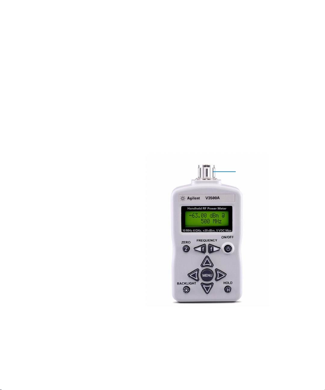
The Keysight V3500A Handheld RF Power Meter, 10 MHz to
6 GHz is a compact handheld instrument designed for
making RF power measurements in both the field as well as
research and development (R&D) laboratory environments.
In the laboratory, the V3500A can be used as an RF power
data logger by transferring data through its built- in USB
interface to a computer, allowing you to perform trend or
drift analysis. For use in the field, the compact size of the
V3500A allows it to be placed in a toolkit. You do not have
to carry both a power meter and a separate sensor module
(the V3500A has a built- in sensor) when conducting
measurement in the field.
Figure 1-1 V3500A Handheld RF Power Meter with backlight turned on
2 V3500A User’s Guide
Page 23

Key features
Initial Inspection
Getting Started 1
• Easy to use interface with LCD display
• Economical single- function instrument
• Wideband (10 MHz to 6 GHz) average RF power
measurements
• Compact size with a built- in display and sensor
• Universal Serial Bus (USB) control interface
• Flexibility of drawing operating power from an on-board
battery, an optional external power supply, or a computer
via the USB interface
When you receive your instrument, inspect the instrument
for any obvious damage such as broken terminals or cracks,
dents, and scratches on the casing that may occur during
shipment.
If any damage is found, notify the nearest Keysight Sales
Office immediately. The front of this manual contains the
warranty information.
Standard purchase items
Verify that you have received the following items with your
V3500A instrument. If anything is missing or damaged,
please contact the nearest Keysight Sales Office.
✔ USB interface cable (Standard- A to Type-B), 2.5 meter
✔ Printed Keysight V3500A Handheld RF Power Meter, 10
MHz to 6 GHz User’s Guide (English)
✔ Keysight V3500A Product Reference CD- ROM
V3500A User’s Guide 3
Page 24

1Getting Started
Optional purchase items
✔ Power supply (V3500A- PWR)
✔ Holster carrying case with shoulder strap (V3500A- SHL)
✔ USB interface cable (Standard- A to Type-B), 2.5 meter
(V3500A- CA1)
✔ Printed Keysight V3500A Handheld RF Power Meter,
10 MHz to 6 GHz User’s Guide (Japanese) (V3500A- ABJ)
✔ Printed Keysight V3500A Handheld RF Power Meter,
10 MHz to 6 GHz User’s Guide (Simplified Chinese)
(V3500A- AB2)
✔ Printed Keysight V3500A Handheld RF Power Meter, 10
MHz to 6 GHz User’s Guide (English) (V3500A- ABA)
Keep the original packaging in case the V3500A has to be
returned to Keysight in the future. Also, include a brief
description of the problem.
Handling Precaution
To maintain high- impedance isolation, ensure that the
V3500A is handled carefully to avoid contamination from
foreign materials such as body oil. Such contamination can
reduce isolation resistance.
To avoid possible contamination, do not touch connector
insulators. If the instrument becomes contaminated, it
should be thoroughly cleaned. Refer to Keysight V3500A
Handheld RF Power Meter, 10 MHz to 6 GHz Service Guide for
more information.
4 V3500A User’s Guide
Page 25
Setting-up your Instrument
Typ e -N ma le
connector nut
Connectivity
You need to set- up the RF connector and USB port
connections properly before making any measurements.
RF connector
Use the Type- N male RF connector with 50 Ω
characteristic impedance (see Figure 1-2) to make RF
signal connections.
Getting Started 1
Figure 1-2 V3500A with Type-N connector nut
V3500A User’s Guide 5
Page 26

1Getting Started
NOTE
Be sure to follow the following guidelines when making
connections.
✔ Maximum input power limitations
Do not connect or apply any power level that is
outside of the V3500A specifications. See “Product
Specifications” on page 96 for a complete list of
specifications.
✔ Connection for a power measurement
While holding the body of the power meter in one
hand, turn the Type- N male connector nut to tighten
the connection (do not turn the body of the V3500A).
Continue to do so until the connection is hand- tight.
It is important to turn the nut of the connector rather
than the body of the power meter when tightening the
connection.
When connecting the Type-N connector of the V3500A to a Type-N female
connector for a power measurement, observe proper practice for
tightening the connection.
6 V3500A User’s Guide
Page 27

Getting Started 1
NOTE
USB type
mini-B port
External power
connector
Full serial
number
USB port
The V3500A has a USB 2.0 interface with mini- B port (see
Figure 1-3). The V3500A can be remotely programmed over
this USB interface.
In addition to remote programming, the V3500A can be
powered by the USB port regardless of whether the batteries
are present or connected to the external power supply
(V3500A- PWR).
The interface is USB 2.0 compatible with an interface speed of 12 Mbps.
Figure 1-3 Full serial number, USB type mini-B port, and external
power connector
V3500A User’s Guide 7
Page 28

1Getting Started
CAUTION
Power supply
You can use either the battery power or the external power
connector to power on your V3500A.
• Battery power
The V3500A can be powered by two AA batteries. If
installed, the batteries will power the V3500A only if the
external power supply and USB are not connected.
Refer to Keysight V3500A Handheld RF Power Meter, 10
MHz to 6 GHz Service Guide for more information.
• External power connector
The external power connector provides a connection for
the optional external power supply (Model V3500A- PWR)
(see Figure 1- 3). If the external power supply is
connected, the V3500A will be powered by the external
power supply — regardless of whether the USB power or
batteries are present.
8 V3500A User’s Guide
Only connect the optional external power supply (V3500A-PWR)
recommended to this connector. Instrument damage may result if
improper power is applied.
The power supply is equipped with an AC line filter and
provides a conditioned +5 VDC, 150 mA power source for
the V3500A.
Page 29

Keysight V3500A Handheld RF Power Meter
User’s Guide
2 Knowing your Instrument
Product at a Glance 10
Product dimensions 10
The front panel keypad 11
How to navigate the menu system 13
How to power on the V3500A 16
Front panel operations 17
Measuring power 17
Zeroing the power meter 18
Setting the input frequency 18
Setting the measurement speed 19
Enabling and disabling high-speed mode 19
Saving the instrument state 20
Recalling the instrument state 20
Setting units: dBm or watts 21
Controlling the backlight 22
Setting the backlight auto-shutoff interval 22
Using relative offset function 23
This chapter specifies the characteristics, environmental
conditions, and specifications of the V3500A Handheld RF
Power Meter. This chapter contains a brief description of the
instrument outlook, front panel operation, and front panel
procedure.
Page 30

2 Knowing your Instrument
79 mm
49 mm
1134 mm
Product at a Glance
Product dimensions
Figure 2-1 V3500A dimensions
10 V3500A User’s Guide
Page 31

The front panel keypad
Figure 2-2 shows the location of the front panel keypad.
Refer to Table 2- 1 for front panel key description and usage.
Figure 2-2 V3500A front panel keypad
Knowing your Instrument 2
Tab l e 2- 1 V3500A keypad functions
Key Description
Press ZERO to measure the offset voltages in the signal path and zero the V3500A. This allows a
more accurate measurement at low power levels. The V3500A RF input may be left disconnected
when it is zeroed, or it may be connected to other hardware, but make sure that no signals are
present on the RF input as this results in inaccurate readings. For example, if the V3500A is
connected to a signal generator, turn off the signal generator's output before pressing the ZERO
keypad. When the V3500A is zeroed, the display will show "Zeroing.....”. The entire operation will
take approximately 30 seconds.
Press FREQUENCY to set the V3500A to the frequency of the input signal. There are two keypads for
adjusting the frequency. The left arrow key decrements the present frequency in 10 MHz steps.
Likewise, the right arrow key increments the present frequency in 10 MHz steps. The present
frequency is displayed on the second line of the display. Pressing and holding one of the frequency
keys down will change the frequency setting rapidly.
Press ON/OFF to turn on or turn off the V3500A.
V3500A User’s Guide 11
Page 32

2 Knowing your Instrument
Tab l e 2- 1 V3500A keypad functions (continued)
Key Description
Press MENU to enter the menu mode. The four arrow keypads are active in menu mode only. When
the V3500A is in normal mode, the four arrow keypads are inactive.
The up and down menu keypads select different menus. For example, these keypads can be used to
change from the “Averaging” menu to “Units” menu.
The left and right menu keypads allow users to adjust the settings in a given menu. For example, in
the “Averaging” menu, these keys are used to select the number of averages performed by
the V3500A.
Under normal mode, the V3500A power reading is updated continuously. In some cases, this may be
undesirable. For example, the V3500A might be connected to a signal source in a location that
makes it difficult to read the display. Press HOLD for the most recent reading to be frozen on the
display and is no longer updated. This allows the user to disconnect the V3500A from the source and
then read the display. Press HOLD again to disable the hold function and the display will once again
be updated continuously. When the hold function is enabled, the letter "H" is displayed on the upper
right-hand corner of the display.
Press MENU to access any functions that are not available to the user directly from the front panel
keypad. It also allows users to enter or exit the V3500A menus. Press MENU once causes the power
display to be replaced with the menu display. The menu can be navigated with the menu navigation
keypads. Press MENU again to exit the menu mode and the display will return to normal mode.
The V3500A display and keypads are backlit to allow visibility in dark environments.
Press BACKLIGHT to turn on and off the LCD backlight display and keypads. In order to conserve
battery power, the backlight will automatically be turned off after one minute delay (default setting).
You can change the delay setting using the V3500A menus.
12 V3500A User’s Guide
Page 33

How to navigate the menu system
NOTE
There is no “enter” keypad to activate a particular menu selection. Once
the left or right menu keypads are used to select one of the choices in a
menu, that choice is automatically activated.
Press MENU to toggle the display between normal and menu
mode. Use the four arrow keypads surrounding the MENU
keypad to navigate and make selections while in menu mode.
Use the up and down menu arrow keypads to scroll through
the available menus and make a selection.
The left and right menu arrow keypads are used to select
available choices in menu mode. All menu commands are
executed immediately when the choice is selected.
The menu map structure is shown in Figure 2- 3 and the
description is shown in Table 2- 2. The menu items in
<> brackets are the default menu values.
Knowing your Instrument 2
Figure 2-3 Menu map structure
V3500A User’s Guide 13
Page 34

2 Knowing your Instrument
Tab l e 2- 2 Menu map structure description
Menu Description Available Values Default
values
Averaging Sets the averaging value. Off, 2, 4, 8, 16, 32 Off
Units Sets the measurement unit. Refer to “Setting units:
dBm, Watts dBm
dBm or watts” on page 21.
Shutdown Sets the auto-shutoff interval. Refer to “Setting the
1m, 5m, 30m, 1hr, Never Never
backlight auto-shutoff interval” on page 22.
BacklightOff Sets the duration prior to the backlight turning off
automatically. Refer to “Controlling the backlight” on
1m, 5m, 10m, 20m, Never 1m
(1 minute)
page 22.
Contrast Sets the LCD display contrast. 0%, 10%, 20%, 30%, 40%, 50%,
50%
60%, 70%, 80%, 90%, 100%
Save State Enables or disables the save state. Refer to “Saving
No, Save No
the instrument state” on page 20.
Recall State Enables or disables the recall state. Refer to “Recalling
No, Recall No
the instrument state” on page 20.
Meas mode Selects between normal or fast mode. Refer to
Norm, Fast Norm
“Enabling and disabling high-speed mode” on page 19.
Firmware Rev Shows the firmware revision used in the instrument. – –
Serial Num
Shows the numerical serial number of the instrument
––
[1]
(without prefix).
Rel Offset Allows users to apply an offset value to the
Off, On Off
measurement. Refer to “Using relative offset
function” on page 23.
[1]
The numerical serial number displayed on the instrument is for reference only. For full serial number (with prefix), please
refer to the printed label shown in Figure 1-3 on page 7.
14 V3500A User’s Guide
Page 35

Knowing your Instrument 2
Examples on how to navigate the menu system
1 Press down arrow keypad to change the active menu from
“AVERAGING” to “UNITS” menu.
2 In the “AVERAGING” menu, the left and right menu
keypads can turn averaging “Off” or select 2, 4, 8, 16, or
32 averages. If the present selection is <2>, and the right
menu key is pressed, the active selection will be changed
to <4> immediately.
V3500A User’s Guide 15
Page 36

2 Knowing your Instrument
NOTE
NOTE
How to power on the V3500A
Use the ON/OFF keypad to turn on or turn off the V3500A.
While operating on battery power, the V3500A has a power
auto-shutoff feature to preserve battery life. This feature
automatically turns the power meter off after a certain
duration. By default, the auto-shutoff feature time
is disabled.
The “SHUTDOWN” menu allows you to change the auto-shutoff interval.
Setting the power auto-shutoff interval
1 Press MENU to enter menu mode.
2 The menu system map as shown in Figure 2-3 will be
shown.
3 Scroll using the down arrow key until “Shutdown” is
displayed.
4 Select your desired time-out interval using the left or
right menu keypads.
To disable the auto-shutoff function, select <Never> for the time-out
interval under “Shutdown” menu.
16 V3500A User’s Guide
Page 37

Front panel operations
NOTE
Measuring power
Knowing your Instrument 2
The V3500A Handheld RF Power Meter can be operated and
programmed using the front panel. All commands and
functions accessible through USB can also be accessed from
the front panel.
Use the following procedure to measure the power of a
signal with the best accuracy.
1 Set frequency reading.
Press left or right FREQUENCY keypads as needed to set an
appropriate frequency. The V3500A can be set from
10 MHz to 6000 MHz in 10 MHz increments.
The instrument returns to the default frequency value setting of 500 MHz
after the instrument is turned off.
2 Zero the V3500A.
Refer to “Zeroing the power meter” on page 18 for more
information.
3 Connect the V3500A RF input port to the signal to be
measured. Refer to “RF connector” on page 5 for more
information.
The top line of the display shows the measured power of the
signal. The measured power will be updated continuously
and displayed accordingly.
In the upper right- hand corner of the display, an “at”
symbol (@) is displayed whenever a new measurement is
completed and the results have been displayed. If this
symbol changes to the letter “H”, the V3500A will hold the
present reading (the instrument is in hold mode). Press
HOLD to return to normal mode.
V3500A User’s Guide 17
Page 38

2 Knowing your Instrument
NOTE
Zeroing the power meter
Zeroing the power meter improves the measurement
accuracy of the V3500A significantly, especially at low power
levels. After the power meter is turned on, you should
always perform zeroing prior to making any measurements.
The V3500A should be zeroed when it warms up, and
periodically when the ambient temperature changes.
1 Prior to zeroing the V3500A, make sure all the RF power
is removed from the V3500A RF input port. This can be
done by disconnecting the RF input, or by disabling the
output of any signal sources connected to V3500A.
2 Once all RF power is removed from the V3500A RF input
port, press ZERO. The V3500A will display the message
“Zeroing...” during the zeroing process. When the display
returns to normal mode, zeroing is complete and
measurements can be made.
Setting the input frequency
The instrument returns to the default frequency value setting of 500 MHz
after the instrument is turned off.
The V3500A has an internal calibration table that corrects
for frequency response variations of its circuitry. For best
accuracy, set the input signal frequency correctly.
1 Press FREQUENCY to set the input frequency. The left
arrow decreases the frequency, and the right arrow
increases the frequency value. The present frequency
setting is displayed on the second line of the display
when the display is in normal mode.
2 Holding either the left or right keypad down will cause
the frequency to decrease or increase rapidly, allowing the
user to quickly set the frequency to the desired value.
18 V3500A User’s Guide
Page 39

Setting the measurement speed
NOTE
In normal operation speed, the V3500A will complete a
power measurement in about 1 second (± 0.5 second
depending on the power level of the input signal). Lower
level signals take longer to measure than higher level signals.
This is due to the fact that more filtering is required to get
a good signal- to- noise ratio when measuring low- level
signals.
If faster measurements are required, set the V3500A to
high- speed mode. In this mode (for measurements greater
than –30 dBm) the V3500A can make approximately
23 measurements per second.
In most cases, the normal measurement speed is the best
choice. Measurement data filtering is greatly reduced in
high- speed mode, resulting in significantly higher
measurement noise than in normal mode.
Knowing your Instrument 2
Enabling and disabling high-speed mode
The instrument returns to the default “Meas mode” setting of <Norm>
when the instrument is turned off.
1 Press MENU to enter menu mode.
2 Scroll using the down menu arrow keypad until “Meas
mode” menu is displayed.
3 Press the left or right menu arrow keypad to select the
desired measurement speed mode. There are two available
options:
• <Norm>: Selects normal measurement speed mode
• <Fast>: Selects high- speed mode
V3500A User’s Guide 19
Page 40

2 Knowing your Instrument
NOTE
CAUTION
NOTE
Saving the instrument state
• The default “Save State” menu setting is <No>.
Saving the state of the instrument places all menu values in the memory of the
instrument so that it can be recalled after the cycling power. Frequency settings
are not saved or recalled.
• The “Save State” feature is only functional when the batteries are stored in the
instrument.
1 Press MENU to enter menu mode.
2 Scroll using the down menu arrow keypad until “Save
State” menu is displayed.
All menu commands are executed immediately when the choice is
selected. Therefore, the Save State command is implemented as soon
as the <Save> menu item is highlighted. There is no undo option— as
soon as the <Save> menu item is selected, the current menu setting
overwrite the previously saved settings.
20 V3500A User’s Guide
3 Use the right arrow menu keypad to select <Save>. This
will save the instrument state in the non- volatile memory
of the V3500A.
Recalling the instrument state
The default “Recall State” menu setting is <No>.
Recalling the instrument state restores all stored menu values in the
V3500A non-volatile memory. Frequency settings are not recalled.
1 Press MENU to enter menu mode.
2 Scroll using the down menu arrow keypad until “Recall
State” menu is displayed.
Page 41

CAUTION
All menu commands are executed immediately when the choice is
NOTE
selected. Therefore, the Recall State command is implemented as soon
as the <Recall> menu item is highlighted. There is no undo option —
as soon as the <Recall> menu item is selected, the saved menu setting
overwrite the present settings.
3 Use the right arrow menu keypad to select <Recall>. This
will recall the instrument state in the non- volatile
memory of the V3500A.
Setting units: dBm or watts
• When operating the V3500A in Watts mode using the front panel, it will
display nW, µW, mW, or W accordingly.
• The instrument returns to the default dBm instrument after the
instrument is turned off.
Knowing your Instrument 2
V3500A User’s Guide 21
Refer to “Units of Measurement” on page 84 for information
on dBm and watts.
1 Press MENU to enter menu mode.
2 Scroll using the down menu arrow keypad until “Units”
menu is displayed.
3 Use the left or right arrow menu keypad to select your
desired units, either <dBm> or <Watts>.
Page 42

2 Knowing your Instrument
NOTE
Controlling the backlight
Setting the backlight auto-shutoff interval
The V3500A LCD display and keypads are backlit to allow
visibility in dark environments. Press BACKLIGHT to turn on
and off the backlight LCD display and keypads. The
backlight will automatically be turned off after a certain
length of time to preserve the battery life. The default time
is one minute.
The instrument returns to the default “BacklightOff” menu setting of
<1m> when the instrument is turned off.
1 Press MENU to enter menu mode.
2 Scroll using the down menu arrow keypad until
“BacklightOff” menu is displayed.
3 Use the left or right arrow menu keypad to select your
desired time interval. Select <Never> to disable the
backlight’s auto- shutoff.
22 V3500A User’s Guide
Page 43

Using relative offset function
The relative offset function allows you to apply an offset
value to the measurement. The relative offset values range
from –99.99 dB to +99.99 dB with 0.01 dB resolution. When
the relative offset function is turned on, the displayed power
is limited to ±99.99 dBm and 999.99 W.
Turning on the relative offset function
When “Rel Offset” is enabled, a flashing letter “O” is
displayed on the upper right-hand corner of the V3500A.
1 Press MENU to enter menu mode.
2 Scroll using the down menu arrow until “Rel Offset” menu
is displayed.
3 Use the right arrow menu keypad to select the <On>
function from the submenu. Enter a relative offset value
using steps shown in Entering a relative offset value.
4 Press MENU to exit.
Knowing your Instrument 2
Entering a relative offset value
1 From the “Rel Offset” menu, use the right arrow menu
keypad to select <Edit>. Notice that the up, down, left,
and right arrow keypads are enabled.
2 Use any of the up, down, left, or right arrow keypads to
edit the individual digits of the relative offset value and
store the value.
3 Use the up and down arrow keypads to change the sign of
the relative offset positive (+) or negative (–) value.
4 Press MENU to exit and store the relative offset value
entered. The relative offset value entered will be applied
to the measurement reading on the V3500A.
When the relative offset value function is enabled and the
value is stored in the V3500A, the letter “O” will flash on
the upper right- hand corner of the display. When the
relative offset value is entered as 0.0, the “@” character
will flash on the upper right- hand corner of the display,
indicating that the relative offset function is not enabled.
V3500A User’s Guide 23
Page 44

2 Knowing your Instrument
NOTE
Powering the V3500A on or off erases any relative offset values entered.
Turning off the relative offset function
1 Press MENU to enter menu mode.
2 Scroll using the down menu arrow until “Rel Offset” menu
is displayed.
3 Use the right arrow menu keypad to select the <Off>
function.
4 Press MENU to exit. The “@” character will flash on the
upper right- hand corner of the display, indicating that the
relative offset function is turned off.
24 V3500A User’s Guide
Page 45

Keysight V3500A Handheld RF Power Meter
User’s Guide
3 Driver Installation and Commands
System Requirements 26
Driver Installation 27
Installing USB driver 27
Installing USB driver (Windows 7) 34
Confirming the USB driver installation 38
Uninstalling the USB driver 41
Installing programming driver 42
Instrument Address 46
Remote USB Operation 47
Introduction 47
Bus connections 47
Remote USB commands 48
Basic driver commands 49
Basic V3500A commands 55
Averaging control commands 56
Measurement speed control commands 57
Unit of measurement commands 58
Relative Offset Commands 59
Miscellaneous commands 60
Examples 61
This chapter provides you the step- by- step programming
driver installation procedure, remote USB operation, and
basic drive commands of the V3500A Handheld RF Power
Meter.
Page 46

3 Driver Installation and Commands
System Requirements
Prior to any installation, please ensure that your PC meets
the following minimum system requirements.
Processor 1.6 GHz Pentium® IV or higher
Operating System Any one of the following Microsoft® Windows® versions:
• Windows 2000 Professional (Service Pack 4) or later
• Windows XP Professional or Home edition (Service Pack 1) or later
• Windows Vista
• Windows 7
Browser Microsoft® Internet Explorer 5.01 or higher
Available Hard Disk Space 1 GB
Available RAM 512 MB or higher is recommended
Video Super VGA (800x600) 256 colors or higher
26 V3500A User’s Guide
Page 47

Driver Installation
NOTE
Driver Installation and Commands 3
The V3500A drivers support the following Microsoft®
operating systems:
• Windows® 7
• Windows Vista
• Windows XP
• Windows 2000
Verify that your PC meets the minimum system requirements
as stated under “System Requirements” on page 26. Follow
the steps below to install the V3500A programming drivers.
The setup.exe file will automatically check and install the Microsoft .Net
Framework if it is not installed on your PC.
Installing USB driver
USB driver installation allows you to install the low-level
drivers that set up the physical communication link
between the V3500A and the PC.
1 Download the driver from the Keysight’s Web site:
2 Execute the file name setup.exe to install the V3500A
software driver.
V3500A User’s Guide 27
Page 48

3 Driver Installation and Commands
3 If the Microsoft .Net Framework is not installed on
your PC, the setup file will prompt you to install it.
Click Install and follow the instructions as shown in the
following images.
28 V3500A User’s Guide
Page 49

Driver Installation and Commands 3
V3500A User’s Guide 29
Page 50

3 Driver Installation and Commands
4 Connect the USB cable between the V3500A instrument
and your PC. Then, connect the V3500A instrument to
the required AC power and turn the instrument on.
5 Your PC will automatically detect the connected
instrument and the Welcome to the InstallShield Wizard for
Agilent V3500A Driver window will appear.
30 V3500A User’s Guide
Page 51

Driver Installation and Commands 3
NOTE
• The V3500A should automatically be turned on when connected to
the USB port of the PC. Turn the instrument on manually if it is not
powered on.
• If the Welcome to the InstallShield Wizard for Agilent V3500A Driver
window does not appear, cycle the power of the V3500A.
• For Windows 7, the PC will not be able to automatically detect the
connected instrument. Refer to “Installing USB driver (Windows 7)” on
page 34 for more information on installing the driver in Windows 7.
Click Next and follow the instructions as shown in the
following images to complete the installation.
V3500A User’s Guide 31
Page 52

3 Driver Installation and Commands
32 V3500A User’s Guide
Page 53

Driver Installation and Commands 3
V3500A User’s Guide 33
Page 54

3 Driver Installation and Commands
NOTE
Installing USB driver (Windows 7)
The V3500A must be connected to the PC via USB before the driver can be
seen under Other devices in the Device Manager window.
1 To install the driver for the connected instrument, go to
Run (search from the Windows Start menu) and type
devmgmt.msc. Click OK.
2 The Device Manager window will appear. Select Other
devices and right- click 3500 Power Meter as shown below.
34 V3500A User’s Guide
Page 55

Driver Installation and Commands 3
3 Click Update Driver Software... and the Update Driver Software
window will appear.
4 Click Browse my computer for driver software to locate the
V3500A USB driver folder. Select the folder Agilent V3500A
Driver, and then click Next.
V3500A User’s Guide 35
Page 56

3 Driver Installation and Commands
5 A Windows Security warning message will appear. Click
Install this driver software anyway to proceed with the
installation.
6 When the installation has completed, click Close to exit
the installation.
36 V3500A User’s Guide
Page 57

Driver Installation and Commands 3
7 You should see the following callout that the installation
is successful.
8 Go to the Device Manager window. Select Other devices and
right- click USB Serial Port. Repeat step 3 to step 6 for the
driver installation.
V3500A User’s Guide 37
Page 58

3 Driver Installation and Commands
Virtual COM port driver, in this
case it occupies COM6
NOTE
Confirming the USB driver installation
1 To confirm the USB driver installation is complete, go to
Start > Run (on the Windows Start menu) and type
devmgmt.msc. Click OK.
2 The Device Manager window will appear. Scroll down to
Ports (COM & LPT) and Universal Serial Bus controllers to
confirm the drivers are installed and present.
If you are using multiple Keysight instruments, you may wish to unplug all
but one, to ascertain the COM port number used by a particular
instrument. You may also differentiate similar instruments by right-clicking
on the device, viewing the Properties and the serial number of
the instrument.
38 V3500A User’s Guide
Page 59

Driver Installation and Commands 3
3 Launch Agilent Connection Expert by clicking the IO icon
on your desktop toolbar.
Click Refresh All to refresh the list of connected
instruments. Right- click COM6 and click Add Instrument.
4 Select Auto-identify this instrument and click OK.
V3500A User’s Guide 39
Page 60

3 Driver Installation and Commands
5 Once the V3500A has been added, right- click and select
Send Commands To This Instrument.
6 Type the command pwr? and click Send & Read to confirm
that the V3500A is properly connected and ready to use.
40 V3500A User’s Guide
Page 61

Uninstalling the USB driver
1 To uninstall the USB driver, go to Start > Run (on the
Windows Start menu) and type devmgmt.msc Click OK.
2 To uninstall the USB driver for the virtual COM port,
scroll down to Ports (COM & LPT) and find the device for
your instrument.
3 Right- click on the device and select Uninstall.
Driver Installation and Commands 3
4 The Confirm Device Removal window will appear. Click OK to
remove the driver.
V3500A User’s Guide 41
Page 62

3 Driver Installation and Commands
Installing programming driver
5 To uninstall the USB driver for the Universal Serial Bus
controller, scroll down to Universal Serial Bus controllers and
find the device for your instrument.
6 Right- click on the device and select Uninstall.
7 The Confirm Device Removal window will appear. Click OK to
remove the driver.
Programming driver installation allows you to install the
high-level drivers that manage the USB interface and
facilitate programming of the V3500A.
In order for your program to be able to communicate with
the programming driver, it must be able to find the
appropriate DLL. The method used to find the
appropriate DLL is dependent on the software used to
create your programs. Refer to the relevant sections below
for further information.
• When using Microsoft Visual Studio.NET
• When using Microsoft Visual Studio 6.0
When using Microsoft Visual Studio.NET
In the installation directory, find the file name
“KeysightV3500A.dll“ and add a reference to this file in your
project. The default setup places the KeysightV3500A.dll file
in the following folder: C:\Program Files\Keysight\
Keysight V3500A Driver. Refer to Adding a reference
(Microsoft Visual Studio.NET) for more information.
42 V3500A User’s Guide
Page 63

Driver Installation and Commands 3
NOTE
An alternative method would be to place a local copy of the
KeysightV3500A.dll in your project directory and add a reference to this
copy. If this alternative method is used, and an updated driver for the
V3500A is later installed, the local copy in the project directory will not be
updated (it will remain the earlier version of the driver).
• Advantage: when updating the V3500A driver, this method removes the
risk that updating the V3500A driver that will break your software.
• Disadvantage: when updating the V3500A driver, this method requires
manual replacement of a copy of the new KeysightV3500A.dll in your
project directory and also rebuilding code to take advantage of the
new driver.
Adding a reference (Microsoft Visual Studio.NET)
The following procedure outlines how to add a reference
while using Microsoft Visual Studio.NET. Adding a
reference in other programming languages is similar.
1 In Microsoft Visual Studio.NET, select the desired
project.
2 Under View menu, select Solution Explorer (alternatively,
press Ctrl-Alt-L).
3 In the Solution Explorer, click + sign next to the project
to expand the project if necessary.
4 Right click References and click Add References to add
the Reference.
5 In the Add Reference window, use Browse to locate the
directory where the V3500A programming driver
KeysightV3500A.dll is stored.
6 Double- click the KeysightV3500A.dll component.
7 Click on OK in the Add Reference window.
KeysightV3500A should now appear under References in
the Solution Explorer window.
V3500A User’s Guide 43
Page 64

3 Driver Installation and Commands
NOTE
NOTE
When using Microsoft Visual Studio 6.0
The procedures for referencing the DLL differ for Visual
Basic 6.0 and Visual C++ 6.0.
In Microsoft Visual Studio 6.0, the KeysightV3500A.tlb file must referenced
in its install location — a reference to a local copy placed in your project
directory cannot be used.
Adding a reference (Visual Basic 6.0)
1 Select Reference menu in your Visual Basic 6.0 project
under Project menu. The References dialog box will
open.
The default setup places the KeysightV3500A.tlb file in the following
folder: C:\Program Files\Keysight\Keysight V3500A
Driver.
2 Use Browse to locate the installation directory.
3 Select “KeysightV3500A.tlb”.
4 Click Open.
5 Verify that the V3500A driver has been added (is
checked).
6 Click OK.
44 V3500A User’s Guide
Page 65

Driver Installation and Commands 3
NOTE
Adding a reference (Microsoft Visual C++ 6.0)
To add the reference in Visual C++ 6.0, make sure the
program contains the following line (no other special
steps are required to add the reference):
#import "C:\Program Files\Keysight\Keysight
V3500A Driver\KeysightV3500A.tlb"
no_namespace named_guids
The above line is correct for an installation in the default directory. If
installed in a different directory, modify the statement accordingly.
V3500A User’s Guide 45
Page 66

3 Driver Installation and Commands
Instrument Address
When performing remote programming, the V3500A serial
number is used as the unique address of the instrument. You
can find the serial number of your instrument using one of
the following methods:
1 Find the serial number on the back label of the
V3500A. Look for an integer number in the range of 1
to 99,999,999.
2 Press MENU to enter menu mode and scroll using the
down menu arrow until “Serial Num” menu is
displayed. The number shown is the serial number of
your instrument.
3 Retrieved from the firmware using the
driver command.
SerialNumber
46 V3500A User’s Guide
Page 67

Remote USB Operation
Introduction
Driver Installation and Commands 3
The V3500A is USB programmable. Commands and functions
accessible from the front panel are also available over USB,
except the following:
• On and off
• Save state
• Recall state
• Shutdown time setting
• Backlight off time setting
The driver for the V3500A is not complicated — a few
commands are necessary to initiate a connection and read
and write from the instrument. Device programming is
accomplished by sending and receiving strings over
the USB. This programming model is very similar to
GPIB programming.
Bus connections
You need to install the required drivers (See “Driver
Installation” on page 27) before using the V3500A remotely.
Then, connect the USB connector on the bottom side of the
V3500A to the USB connector of the controller (see “USB
port” on page 7).
V3500A User’s Guide 47
Page 68

3 Driver Installation and Commands
NOTE
Remote USB commands
You need to perform the following steps in order to perform
remote USB commands with the V3500A.
1 Set the serial number in the software. The numerical
serial number of the V3500A will be used as the
instrument unique address for communication and can be
found underneath the barcode on the back panel of the
V3500A or displayed using the menu button (see “How to
navigate the menu system” on page 13).
2. Initialize the V3500A.
Refer to “Basic V3500A commands” on page 55 for more information.
48 V3500A User’s Guide
Page 69

Driver Installation and Commands 3
Basic driver commands
In each driver command usage section, myPM is an instance
of a power meter class that has been created. Refer to “Basic
V3500A commands” on page 55 for language- specific sample
applications.
Command Name SerialNumber
Description SerialNumber is a property used to control which specific
V3500A instrument is accessed. SerialNumber is a 32- bit
signed integer (1 to 99,999,999).
Usage C#.NET
int SN = 10973300;
myPM.SerialNumber=SN;
Visual Basic.NET
Dim SN As Integer
SN=10973300
myPM.SerialNumber=SN
Visual C++.NET
int SN=10973300;
myPM->SerialNumber=SN;
Visual Basic 6.0
Dim SN As Long
SN=10973300
myPM.SerialNumber=SN
Visual C++ 6.0
int SN=10973300;
myPM->SerialNumber=SN;
Parameters myPM refers to the created V3500A object.
SN is the serial number (32- bit signed integer) of the V3500A
being checked.
V3500A User’s Guide 49
Page 70

3 Driver Installation and Commands
Command Name IsDeviceAvailable()
Description This int function checks the status of the device pointed to
Usage C#.NET
by SerialNumber.
int SN=10973300;
int MeterAvailable=myPM.IsDeviceAvailable(SN);
Visual Basic.NET
Dim SN As Integers
SN=10973300
Dim MeterAvailable As Integer
MeterAvailable = myPM.IsDeviceAvailable(SN)
Visual C++.NET
int SN=10973300;
int MeterAvailable=myPM->IsDeviceAvailable(SN);
Visual Basic 6.0
Dim SN As Long
SN=10973300
Dim MeterAvailable As Integer
MeterAvailable=myPM.IsDeviceAvailable(SN)
Visual C++ 6.0
int SN = 10973300;
int MeterAvailable=myPM.IsDeviceAvailable(SN);
Parameters myPM refers to the created V3500A object.
SN is the serial number (32- bit signed integer) of the V3500A
being checked.
MeterAvailable is the integer variable created containing
the device status.
Return Value Returns a 32- bit integer with one of the following values:
• 0: Unavailable — the device may have been opened by
another program.
• 1: Available.
• –1: Absent—the device was not found.
50 V3500A User’s Guide
Page 71

Driver Installation and Commands 3
Command Name Initialize()
Description This void function opens the link between the V3500A and the
PC. The SerialNumber property must be set prior
to executing.
Usage C#.NET
myPM.SerialNumber=10973300;
myPM.Initialize();
Visual Basic.NET
myPM.SerialNumber=10973300
myPM.Initialize()
Visual C++.NET
myPM->SerialNumber=10973300;
myPM->Initialize();
Visual Basic 6.0
myPM.SerialNumber=10973300
myPM.Initialize
Visual C++ 6.0
myPM.SerialNumber=10973300;
myPM->Initialize();
Parameters myPM refers to the created V3500A object.
V3500A User’s Guide 51
Page 72

3 Driver Installation and Commands
Command Name SendString
Description Use this command to send and receive string messages from
Usage C#.NET
Parameters myPM refers to the created V3500A object.
the V3500A — all communication with the V3500A is
accomplished using this command.
string Reply=myPM.SendString("*RST\n");
Visual Basic.NET
Dim Reply As String
Reply=myPM.SendString("*RST" & vbLf)
Visual C++.NET
String * Reply;
Reply=myPM->SendString("*RST\n");
Visual Basic 6.0
Dim Reply As String
Reply = myPM.SendString("*RST" & vbCrLf)
Visual C++ 6.0
BSTR Reply;
Reply=myPM->SendString("*RST\n");
52 V3500A User’s Guide
Page 73

Driver Installation and Commands 3
Command Name Close()
Description This command disconnects the program connection to the
V3500A. After the connection is disconnected, the V3500A is
available for use with other programs.
Usage C#.NET
myPM.Close();
Visual Basic.NET
myPM.Close()
Visual C++.NET
myPM->Close();
Visual Basic 6.0
myPM.Close
Visual C++ 6.0
myPM->Close();
Parameters myPM refers to the created V3500A object.
V3500A User’s Guide 53
Page 74

3 Driver Installation and Commands
Command Name FindUninitializedDevices()
Description Use this command to return a string containing a listing of
Usage C#.NET
Parameters myPM refers to the created V3500A object.
[1]
serial numbers of all uninitialized
V3500A
(comma- delimited). If no un- initialized V3500A are present,
the string is empty.
string List;
List=myPM.FindUninitializedDevices();
Visual Basic.NET
Dim List As String
List = myPM.FindUninitializedDevices()
Visual C++.NET
String * List;
List = myPM->FindUninitializedDevices();
Visual Basic 6.0
Dim List As String
List=myPM.FindUninitializedDevices()
Visual C++ 6.0
BSTR List;
List=myPM->FindUninitializedDevices();
List is the string variable containing the returned serial
number(s).
[1]
The statement “uninitialized V3500A” refers to power meters which are connected to your
computer, but have not had the Initialize() function called on them. Also, when Close()
is called on initialized devices, they return to the uninitialized state and are visible to the
FindUninitializedDevices() command.
54 V3500A User’s Guide
Page 75

Driver Installation and Commands 3
Basic V3500A commands
Command Name Reset
Description This command resets the V3500A to its factory
power- on state.
Syntax *RST<LF>
Response OK
Command Name Triggered power read
Description This is the basic measurement command for the V3500A.
Syntax *TRG<LF>
Response <Value>
Return value Returns the present V3500A reading.
Comments The present read cycle of the V3500A is interrupted, and a
new one is started. The measurement from the new cycle
is returned.
Command Name Non-triggered power read
Description This command returns the present reading of the V3500A.
Syntax PWR? <LF>
Response <Value>
Comments This is a non- triggered measurement. If the input power has
changed during the present measurement cycle, the measured
power may be unpredictable.
Command Name Zero command
Description This command zeroes the V3500A.
Syntax ZERO<LF>
Response OK
Comments This internal correction routine removes offset errors in the
measurement. This is necessary to preserve accuracy when
measuring low- level signals.
V3500A User’s Guide 55
Page 76

3 Driver Installation and Commands
Command Name Set frequency
Description This command sets the operating frequency of the V3500A.
Syntax FREQ<Value><LF>
Response OK
Comments The instrument of measurement is Megahertz (MHz).
Averaging control commands
Command Name Set averaging factor
Description This command sets how many averages are taken before
Syntax SETAVG<Value><LF>
Response OK
Comments The valid range of <Value> is 0 through 5 (see Table 3- 1).
returning a power measurement.
Tab l e 3- 1 SETAVG command values
<Value> Number of averages taken
01
12
24
38
416
532
[1]
Equivalent to averaging disabled.
[1]
56 V3500A User’s Guide
Page 77

Driver Installation and Commands 3
NOTE
Sending a value using this command results in taking averages of 2x
measurements (where x = <Value>).
For example:
1
• Sending SETAVG<1><LF> causes the average factor to take 2
or 2
measurements
2
• Sending SETAVG<2><LF> causes the average factor to take 2
or 4
measurements
3
• Sending SETAVG<3><LF> causes the average factor to take 2
or 8
measurements
When <Value> = 0, (sending SETAVG 0), the number of measurements
is set to 1, and is equivalent to averaging disabled.
Command Name Get averaging factor
Description This command reads and returns the averaging factor, which
is equal to log
Syntax AVG?<LF>
Response <Value>
Comments A value of 0 is equivalent to having averaging turned off.
(number of measurements per average).
2
Measurement speed control commands
Command Name Set normal speed mode
Description This command sets the V3500A to normal speed mode.
Syntax NMODE<LF>
Response OK
Comments Normal speed mode is the default mode of operation.
The V3500A accuracy specifications apply in normal mode.
Measurement speed is level- dependent.
V3500A User’s Guide 57
Page 78

3 Driver Installation and Commands
Command Name Set high speed mode
Description This command sets the V3500A to high speed mode.
Syntax HSMODE<LF>
Response OK
Comments High speed mode turns off all internal averaging and filtering.
Unit of measurement commands
Command Name dBm mode
Description This command sets the V3500A to dBm mode.
Syntax UDBM<LF>
Response OK
Comments Send this command to express the remote and front panel
Measurement noise is higher (especially at low signal levels),
but the measurement speed is much faster.
measurements in dBm.
Command Name watts mode
Description This command sets the V3500A to watts mode.
Syntax UMW<LF>
Response OK
Comments Send this command to express remote measurements in units
of watts, regardless of the units displayed on the front panel.
The front panel display will express measurements in units of
watts, milliwatts, or microwatts, as appropriate.
58 V3500A User’s Guide
Page 79

Driver Installation and Commands 3
Relative Offset Commands
Command Name Set relative offset
Description This command sets a relative offset value.
Syntax SETREL<Value><LF>
Command Name Check for the relative offset value
Description This command checks for and returns the set relative offset
value.
Syntax RELVAL?<LF>
Command Name Turn relative offset on
Description This command sets the relative offset to ON.
Syntax RELON<LF>
Command Name Turn relative offset off
Description This command sets the relative offset to OFF.
Syntax RELOFF<LF>
Command Name Check status of the relative offset
Description This command checks the status of the relative offset. If it is
ON, a “1” is returned, and if it is OFF, a “0” is returned. If it
is in EDIT mode, a “2” is returned.
Syntax REL?<LF>
V3500A User’s Guide 59
Page 80

3 Driver Installation and Commands
Miscellaneous commands
Command Name Backlight on
Description This command turns on the LCD display and keyboard
Syntax BLON<LF>
Response OK
Comments The backlight will remain on for the length of time specified
Command Name Backlight off
Description This command turns off the LCD display and keyboard
Syntax BLOFF<LF>
Response OK
backlight.
by the backlight timer. The timer is controllable from the front
panel using the menu button (see “How to navigate the menu
system” on page 13).
backlight.
Command Name Get serial number
Description This command returns the numeric serial number of the
instrument.
Syntax SN?<LF>
Response <Value>
Command Name Retrieve firmware revision
Description This command returns the firmware revision.
Syntax FWREV?<LF>
60 V3500A User’s Guide
Page 81

Examples
Driver Installation and Commands 3
This section provides example programs that initialize the
V3500A, make measurements, and close the V3500A.
Examples are provided using the following programming
language:
• Microsoft Visual Studio.NET
• Microsoft Visual Basic 6.0
• Microsoft Visual C++ 6.0
Microsoft Visual Studio.NET
The following examples are console applications. Follow the
steps below to run in Microsoft Visual Studio.NET.
1 Create a new.NET console application project.
2 Delete the contents of the source file.
3 Copy the desired applicable example code into the source
code file.
• “Example code using Microsoft C#.NET” on page 62
• “Example code using Microsoft Visual Basic.NET” on
page 65
• “Example code using Microsoft Visual C++.NET” on
page 68
4 Add a reference to the DLL — refer to “Adding a reference
(Microsoft Visual Studio.NET)” on page 43.
V3500A User’s Guide 61
Page 82

3 Driver Installation and Commands
Example code using Microsoft C#.NET
This sample program shows how to program the V3500A using Microsoft C#.NET 2003.
using System;
namespace ExampleV3500A
{
class Class1
{
[STAThread]
static void Main(string[] args)
{
string Reply;
double MeasuredPower;
// The namespace for the V3500A driver is KeysightV3500A_NS.
// First, create the V3500A object.
KeysightV3500A_NS.KeysightV3500A myPM =new
KeysightV3500A_NS.KeysightV3500A();
// Set the serial number and check that the meter is available
int SN=10973300; // Set this to the numerical serial number of your V3500A (without
prefix)
int MeterAvailable=myPM.IsDeviceAvailable(SN);
// A return value of 1 means the V3500A is available.
// A value of –1 means it is absent, and a value of 0 means it is unavailable (for example, it
may be in use by another program).
if (MeterAvailable != 1)
{
Console.WriteLine("PowerMeter not available;
status={0}",MeterAvailable); return;
}
Console.WriteLine("V3500A serial number {0} is available", SN);
myPM.SerialNumber=SN;
62 V3500A User’s Guide
Page 83

Driver Installation and Commands 3
// Initialize the V3500A
try
{
myPM.Initialize();
}
// If initialization fails:
catch(Exception e)
{
Console.WriteLine("Error initializing PowerMeter: "+e.Message);
return;
}
Console.WriteLine("V3500A initialized");
// Now we can communicate with the V3500A.
// Configure the V3500A for a measurement:
try
{
Reply=myPM.SendString("*RST\n"); // Reset the power meter
CheckForOK(Reply);
Reply=myPM.SendString("FREQ1000\n"); // Set the frequency to 1000 MHz
CheckForOK(Reply);
}
// If an error occurred:
catch(Exception e2)
{
Console.WriteLine("Error communicating with PowerMeter:
"+e2.Message);
return;
}
Console.WriteLine("V3500A configured");
// Take a reading:
V3500A User’s Guide 63
Page 84

3 Driver Installation and Commands
try
{
Reply=myPM.SendString("*TRG\n");
MeasuredPower=Convert.ToDouble(Reply);
}
// If an error occurred:
catch(Exception e3)
{
Console.WriteLine("Error reading power from the PowerMeter:
"+e3.Message);
return;
}
Console.WriteLine("Measured power was {0:F2} dBm",MeasuredPower);
}
static void CheckForOK(string Message)
{
if (Message.Equals("OK"))
return;
else
{
Console.WriteLine("Expected an 'OK' from the V3500A; received:
"+Message);
}
}
}
}
64 V3500A User’s Guide
Page 85

Driver Installation and Commands 3
Example code using Microsoft Visual Basic.NET
' This sample program shows how to program the Keysight V3500A PowerMeter using Microsoft Visual
Basic .NET 2003
Module Module1
Sub Main()
Dim MeasuredPower As Double
Dim Reply As String
Dim SN As Integer
Dim MeterAvailable As Integer
' The namespace for the V3500A driver is KeysightV3500_NS
' First, create the PowerMeter object
Dim myPM As KeysightV3500A_NS.KeysightV3500A
myPM = New KeysightV3500A_NS.Keysight3500A
'Set the serial number and check that the meter is available
SN = 10973300 'Set this to the numerical serial number of your V3500A (without prefix)
MeterAvailable = myPM.IsDeviceAvailable(SN)
' A return value of 1 means the PowerMeter is available.
' A value of –1 means it is absent, and a value of 0 means it is unavailable (for example, it may
be in use by another program).
If (MeterAvailable <> 1) Then
Dim Message As String
Message = "PowerMeter is not available; status=" +
MeterAvailable.ToString()
Console.WriteLine(Message)
Exit Sub
End If
Console.WriteLine("V3500A serial number {0} is available", SN)
myPM.SerialNumber = SN
V3500A User’s Guide 65
Page 86

3 Driver Installation and Commands
' Initialize the PowerMeter
Try
myPM.Initialize()
' If initialization fails:
Catch e As Exception
Console.WriteLine("Error opening V3500A: " & e.Message)
Exit Sub
End Try
Console.WriteLine("V3500A initialized")
' Now we can communicate with the PowerMeter.
' Configure the PowerMeter for a measurement:
Try
Reply = myPM.SendString("*RST" & vbLf) 'Reset the PowerMeter
CheckForOK(Reply)
Reply = myPM.SendString("FREQ1000" & vbLf) 'Set the frequency to 1000 MHz
CheckForOK(Reply)
' If an error occurred:
Catch e2 As Exception
Console.WriteLine("Error sending to V3500A: " & e2.Message)
Exit Sub
End Try
Console.WriteLine("V3500A configured")
' Take a reading:
Try
Reply = myPM.SendString("*TRG" & vbLf) ' Trigger a power measurement
MeasuredPower = Convert.ToDouble(Reply)
Catch e3 As Exception
Console.WriteLine("Error reading power from V3500A: " & e3.Message)
Exit Sub
66 V3500A User’s Guide
Page 87

Driver Installation and Commands 3
End Try
Console.WriteLine("The measured power was " & MeasuredPower.ToString())
' Now that we're done, close the V3500A, making available for other users
myPM.Close()
End Sub
Private Sub CheckForOK(ByVal Message As String)
If (Message.Equals("OK")) Then
Exit Sub
End If
Console.WriteLine("Expected an 'OK' from the V3500A, received: " & Message)
End Sub
End Module
V3500A User’s Guide 67
Page 88

3 Driver Installation and Commands
Example code using Microsoft Visual C++.NET
// This sample program shows how to program the V3500A using Microsoft Visual C++.NET 2003
#include "stdafx.h"
#using <mscorlib.dll>
using namespace System;
using namespace KeysightV3500A_NS;
int _tmain()
{
String * Reply;
double MeasuredPower;
void CheckForOK(String * Msg);
// The namespace for the V3500A driver is KeysightV3500A_NS.
// First, create the V3500A object.
KeysightV3500A_NS::KeysightV3500A *myPM =new KeysightV3500A();
// Set the serial number and check that the meter is available.
int SN=10973300; // Set this to the numerical serial number of your V3500A
(without prefix)
int MeterAvailable=myPM->IsDeviceAvailable(SN);
// A return value of 1 means the V3500A is available.
// A value of –1 means it is absent, and a value of 0 means it is unavailable (for example, it may
be in use by another program).
if (MeterAvailable != 1)
{
Console::WriteLine(S"PowerMeter not available;
status={0}",__box(MeterAvailable));
return 0;
}
Console::WriteLine("V3500A serial number {0} is available", __box(SN));
myPM->SerialNumber=SN;
// Initialize the V3500A.
68 V3500A User’s Guide
Page 89

Driver Installation and Commands 3
try
{
myPM->Initialize();
}
// If initialization fails:
catch(Exception *e)
{
Console::Write(S"Error initializing PowerMeter: ");
Console::WriteLine(e->Message);
return 0;
}
Console::WriteLine(S"V3500A initialized");
// Now we can communicate with the V3500A.
// Configure the V3500A for a measurement:
try
{
Reply=myPM->SendString("*RST\n"); // Reset the power meter
CheckForOK(Reply);
Reply=myPM->SendString("FREQ1000\n"); // Set the frequency to 1000 MHz
CheckForOK(Reply);
}
// If an error occurred:
catch(Exception *e2)
{
Console::Write(S"Error communicating with PowerMeter: ");
Console::WriteLine(e2->Message);
return 0;
}
Console::WriteLine(S"V3500A configured for power measurement");
V3500A User’s Guide 69
Page 90

3 Driver Installation and Commands
// Take a reading:
try
{
Reply=myPM->SendString("*TRG\n");
MeasuredPower=Convert::ToDouble(Reply);
}
// If an error occurred:
catch(Exception *e3)
{
Console::Write(S"Error reading power from the PowerMeter: ");
Console::WriteLine(e3->Message);
return 0;
}
Console::WriteLine(S"Measured power was {0:F2} dBm",__box(MeasuredPower));
return 1;
}
void CheckForOK(String * Message)
{
if (Message->Equals("OK"))
return;
else
{
Console::Write(S"Expected an 'OK' from the V3500A; received: ");
Console::WriteLine(Message);
}
}
70 V3500A User’s Guide
Page 91

Driver Installation and Commands 3
Microsoft Visual Basic 6.0
This example section contains a Windows Forms application.
Follow the steps below to run in Microsoft Visual Basic 6.0:
1 Create a new Windows Forms project.
2 Delete the source code of the newly created Windows
Forms project.
3 Copy the following code into the source code file.
4 Create three controls on the form:
• A button named btnReadPower
• A button named btnExit
• A text box named txtMessages
5 Add a reference to the DLL — refer to “Adding a reference
(Visual Basic 6.0)” on page 44.
Example code using Microsoft Visual Basic 6.0
This sample program shows how to program the V3500A using Microsoft Visual Basic 6.0.
Dim myPM As New KeysightV3500A.KeysightV3500A
Dim Message As String
Private Sub btnExit_Click()
myPM.Close
End
End Sub
Private Sub btnReadPower_Click()
Dim MeasuredPower As Double
Dim Reply As String
' Now we can communicate with the V3500A.
' Configure the V3500A for a measurement:
On Error GoTo Err_Failed_Setup
Reply = myPM.SendString("*RST" & vbCrLf) ' Reset the V3500A
CheckForOK(Reply)
V3500A User’s Guide 71
Page 92

3 Driver Installation and Commands
Reply = myPM.SendString("FREQ1000" & vbCrLf) ' Set the frequency to 1000 MHz
CheckForOK(Reply)
Message = Message & "V3500A configured." & vbCrLf
txtMessages.Text = Message
'Take a reading:
On Error GoTo Err_Failed_Read
Reply = myPM.SendString("*TRG" & vbCrLf)
Message = Message & "Measured power: " & Reply & " dBm." & vbCrLf
txtMessages.Text = Message
Exit Sub
Err_Failed_Setup:
Message = Message & "Error configuring V3500A for measurement: " &
Err.Description & vbCrLf
txtMessages.Text = Message
Exit Sub
Err_Failed_Read:
Message = Message & "Error reading power from V3500A: " & Err.Description &
vbCrLf
txtMessages.Text = Message
Exit Sub
Err_Failed_Send:
MsgBox("Error during send " & Err.Description)
End Sub
Private Sub CheckForOK(ByVal Msg As String)
Dim StringCompare As Integer
StringComp = StrComp(Msg, "OK")
If (StringCompare = 0) Then
Exit Sub
Else
72 V3500A User’s Guide
Page 93

Driver Installation and Commands 3
Message = Message & "Expected an 'OK' from the V3500A; received: " & Msg &
vbCrLf
txtMessages.Text = Message
End If
End Sub
Private Sub Form_Load()
Dim SN As Long
Dim MeterAvailable As Integer
Message = ""
' Attempt to register the V3500A DLL
On Error GoTo Err_DLL_Not_Registered
Message = Message & "Successfully created V3500A object." & vbCrLf
txtMessages.Text = Message
' Set the serial number and check that the meter is available
SN = 10973300 ' Set this to the numerical serial number of your V3500A (without prefix)
MeterAvailable = myPM.IsDeviceAvailable(SN)
' A return value of 1 means the V3500A is available.
' A value of –1 means it is absent, and a value of 0 means it is unavailable (for example, it may be
in use by another program).
If (MeterAvailable <> 1) Then
Message = Message & "PowerMeter is not available; status=" & MeterAvailable &
vbCrLf
txtMessages.Text = Message
Exit Sub
End If
Message = Message & "V3500A serial number " & SN & " is available." & vbCrLf
txtMessages.Text = Message
myPM.SerialNumber = SN
' Initialize the V3500A
On Error GoTo Err_Failed_Initialize
V3500A User’s Guide 73
Page 94

3 Driver Installation and Commands
myPm.Initialize
Message = Message & "V3500A successfully initialized." & vbCrLf
txtMessages.Text = Message
Exit Sub
Err_DLL_Not_Registered:
' Check to see if error 429 occurs
If Err.Number = 429 Then
Message = Message & "Failed To Register V3500A DLL" & vbCrLf
Else
Message = Message & "Error creating V3500A object: " & Err.Description &
vbCrLf
End If
txtMessages.Text = Message
Exit Sub
Err_Failed_Initialize:
Message = Message & "Error initializing V3500A: " & Err.Description & vbCrLf
txtMessages.Text = Message
Exit Sub
End Sub
74 V3500A User’s Guide
Page 95

Driver Installation and Commands 3
NOTE
Microsoft Visual C++ 6.0
This example is a console application. Follow the steps
below to run in Visual C++ 6.0:
1 Create a new Win32 Console Application.
2 Delete the source code of the newly created console
application project.
3 Copy the following code into the source code file.
Although Visual C++ 6.0 does not need any special steps to reference the
DLL, make sure the code refers to the correct installation directory — refer
to “Adding a reference (Microsoft Visual C++ 6.0)” on page 45. In the
sample code below, the specific program statement regarding the driver
file installation is in bold-face type style.
Example code using Microsoft Visual C++ 6.0
This sample program shows how to program the V3500A using Microsoft Visual C++ 6.0.
#include "stdafx.h"
#include <atlbase.h>
#include <atlconv.h>
#include <iostream.h>
#include <windows.h>
#include <stdio.h>
#pragma warning (disable: 4278)
#import "C:\Program Files\Keysight\Keysight V3500A Driver KeysightV3500A.tlb" \
no_namespace named_guids
void dump_com_error(_com_error &e);
void CheckForOK(BSTR Message);
V3500A User’s Guide 75
Page 96

3 Driver Installation and Commands
int main(int argc, char* argv[])
{
PMInterface *myPM = NULL;
BSTR Reply=NULL;
int MeterAvailable=0;
int SN;
USES_CONVERSION; // Enables use of ATL string conversion macros
CoInitialize(NULL); // Initializes the COM library on the current thread
// Create an instance of the V3500A driver:
HRESULT hr = CoCreateInstance(CLSID_KeysightV3500A,NULL, CLSCTX_INPROC_SERVER,
IID_PMInterface, reinterpret_cast<void**>(&myPM));
if (FAILED(hr))
{
printf("Couldn't create an instance of the V3500A driver!... 0x%x\n", hr);
return 0;
}
// Set the serial number and check that the meter is available
SN=10973300; // Set this to the numerical serial number of your V3500A (without prefix)
try
{
MeterAvailable=myPM->IsDeviceAvailable(SN);
}
catch (_com_error& e)
{
cout << "COM error on IsDeviceAvailable"<<endl;
dump_com_error(e);
return 0;
}
76 V3500A User’s Guide
Page 97

Driver Installation and Commands 3
// A return value of 1 from IsDeviceAvailable() means the V3500A is available.
// A value of –1 means it is absent, and a value of 0 means it is unavailable (for example, it may be
in use by another program).
if (MeterAvailable != 1)
{
cout << "V3500A PowerMeter is not available; status= "<<MeterAvailable<<endl;
return 0;
}
cout<<"V3500A serial number "<< SN << " is available"<<endl;
myPM->SerialNumber=SN;
// Initialize the V3500A
try
{
myPM->Initialize();
}
// This catches errors with COM:
catch (_com_error& e)
{
cout << "COM error initializing V3500A:"<<endl;
dump_com_error(e);
}
// This catches all other errors.
catch (...)
{
cout << "Error initializing" << endl;
return 0;
}
V3500A User’s Guide 77
Page 98

3 Driver Installation and Commands
cout << "V3500A initialized" << endl;
// Setup the V3500A for a measurement:
try
{
Reply=myPM->SendString("*RST\n"); // Reset the V3500A
CheckForOK(Reply);
Reply=myPM->SendString("FREQ1000\n"); // Set the frequency to 1000 MHz
CheckForOK(Reply);
}
// This catches errors with COM:
catch (_com_error& e)
{
cout << "COM error while programming V3500A:"<<endl;
dump_com_error(e);
}
// This catches all other errors.
catch (...)
{
cout << "Error programming V3500A" << endl;
}
cout << "V3500A configured for power measurement" << endl;
// Take a reading:
try
{
Reply=myPM->SendString("*TRG\n");
cout << "Measured power: " << W2A(Reply) << endl;
}
catch (_com_error& e)
78 V3500A User’s Guide
Page 99

Driver Installation and Commands 3
{
cout << "COM error while making a power measurement with V3500A"<<endl;
dump_com_error(e);
}
catch (...)
{
cout << "Error reading power from V3500A" << endl;
}
myPM->Release();
myPM=NULL;
CoUninitialize();
return 1;
}
void dump_com_error(_com_error &e)
{
_tprintf(_T("COM Error Information:\n"));
_tprintf(_T("Code = %08lx\n"), e.Error());
_tprintf(_T("Code meaning = %s\n"), e.ErrorMessage());
_bstr_t bstrSource(e.Source());
_bstr_t bstrDescription(e.Description());
_tprintf(_T("Source = %s\n"), (LPCTSTR) bstrSource);
_tprintf(_T("Description = %s\n"), (LPCTSTR) bstrDescription);
}
void CheckForOK(BSTR Message)
{
USES_CONVERSION; // Enables use of ATL string conversion macros
char ExpectedReturn[]="OK";
char *ActualReturn=W2A(Message);
V3500A User’s Guide 79
Page 100

3 Driver Installation and Commands
int Result=strcmp(ActualReturn,ExpectedReturn);
if (Result)
{
cout << "Expected an 'OK' from the V3500A, received " << W2A(Message) << endl;
}
}
80 V3500A User’s Guide
 Loading...