

Page 1

Test Equipment Depot - 800.517.8431 - 99 Washington Street Melrose, MA 02176 - TestEquipmentDepot.com
Keysight N2002A
Noise Source Test Set
User’s Guide
Page 2

Notices
© Keysight Technologies, Inc.
2003-2015
No part of this manual may be
reproduced in any form or by any
means (including electronic storage
and retrieval or translation into a
foreign language) without prior
agreement and written consent from
Keysight Technologies, Inc. as
governed by United States and
international copyright laws.
Trademark Acknowledgments
Manual Part Number
N2002-90003
Edition
Edition 1, March 2015
Printed in USA/Malaysia
Published By:
Keysight Technologies
1400 Fountaingrove Parkway
Santa Rosa, CA 95403
Warranty
THE MATERIAL CONTAINED IN THIS
DOCUMENT IS PROVIDED “AS IS,”
AND IS SUBJECT TO BEING
CHANGED, WITHOUT NOTICE, IN
FUTURE EDITIONS. FURTHER, TO
THE MAXIMUM EXTENT PERMITTED
BY APPLICABLE LAW, KEYSIGHT
DISCLAIMS ALL WARRANTIES,
EITHER EXPRESS OR IMPLIED WITH
REGARD TO THIS MANUAL AND
ANY INFORMATION CONTAINED
HEREIN, INCLUDING BUT NOT
LIMITED TO THE IMPLIED
WARRANTIES OF
MERCHANTABILITY AND FITNESS
FOR A PARTICULAR PURPOSE.
KEYSIGHT SHALL NOT BE LIABLE
FOR ERRORS OR FOR INCIDENTAL
OR CONSEQUENTIAL DAMAGES IN
CONNECTION WITH THE
FURNISHING, USE, OR
PERFORMANCE OF THIS
DOCUMENT OR ANY INFORMATION
CONTAINED HEREIN. SHOULD
KEYSIGHT AND THE USER HAVE A
SEPARATE WRITTEN AGREEMENT
WITH WARRANTY TERMS
COVERING THE MATERIAL IN THIS
DOCUMENT THAT CONFLICT WITH
THESE TERMS, THE WARRANTY
TERMS IN THE SEPARATE
AGREEMENT WILL CONTROL.
Technology Licenses
The hardware and/or software
described in this document are
furnished under a license and may be
used or copied only in accordance
with the terms of such license.
Restricted Rights Legend
U.S. Government Rights. The
Software is “commercial computer
software,” as defined by Federal
Acquisition Regulation (“FAR”) 2.101.
Pursuant to FAR 12.212 and
27.405-3 and Department of Defense
FAR Supplement (“DFARS”)
227.7202, the U.S. government
acquires commercial computer
software under the same terms by
which the software is customarily
provided to the public. Accordingly,
Keysight provides the Software to
U.S. government customers under its
standard commercial license
a. The license set forth in the EULA
represents the exclusive authority by
which the U.S. government may use,
modify, distribute, or disclose the
Software. The EULA and the license
set forth therein, does not require or
permit, among other things, that
Keysight: (1) Furnish technical
information related to commercial
computer software or commercial
computer software documentation
that is not customarily provided to
the public; or (2) Relinquish to, or
otherwise provide, the government
rights in excess of these rights
customarily provided to the public to
use, modify, reproduce, release,
perform, display, or disclose
commercial computer software or
commercial computer software
documentation. No additional
government requirements beyond
those set forth in the EULA shall
apply, except to the extent that those
terms, rights, or licenses are
explicitly required from all providers
of commercial computer software
pursuant to the FAR and the DFARS
and are set forth specifically in writing
elsewhere in the EULA. Keysight shall
be under no obligation to update,
revise or otherwise modify the
Software. With respect to any
technical data as defined by FAR
2.101, pursuant to FAR 12.211 and
27.404.2 and DFARS 227.7102, the
U.S. government acquires no greater
than Limited Rights as defined in
FAR 27.401 or DFAR 227.7103-5 (c),
as applicable in any technical data..
Safety Notices
CAUTION
A CAUTION notice denotes a
hazard. It calls attention to an
operating procedure, practice, or
the like that, if not correctly
performed or adhered to, could
result in damage to the product
or loss of important data. Do not
proceed beyond a CAUTION
notice until the indicated
conditions are fully understood
and met.
WARNING
A WARNING notice denotes a
hazard. It calls attention to an
operating procedure, practice, or
the like that, if not correctly
performed or adhered to, could
result in personal injury or death.
Do not proceed beyond a
WARNING notice until the
indicated conditions are fully
understood and met.
Page 3

iii
Page 4

General Safety Information
This instrument has been designed and tested in accordance with IEC Publication
61010-1+A1+A2:1992 Safety requirements for Electrical Equipment for Measurement, Control
and Laboratory Use and has been supplied in a safe condition.
The instruction documentation contains information and warnings which must be followed by the user to
ensure safe operation and to maintain the instrument in a safe condition.
WARNING No operator serviceable parts inside, refer servicing to service trained
personnel.
WARNING If this instrument is not used as specified, the protection provided by the equipment could be
impaired. This instrument must be used in a normal condition (in which all means of protection
are intact only).
CAUTION This instrument is designed for use in Installation Category I and Pollution Degree 2
as per IEC 61010 and 60664 respectively.
NOTE This product does not contain an operator replaceable fuse. Disregard the marking
referring to the '~ Line Fuse'. This is not a mains operated unit.
iv
Page 5
Safety Symbols
The following symbols on the instrument and in the manual indicate precautions which must be taken to
maintain safe operation of the instrument.
The Instruction Documentation Symbol. The product is marked with this symbol
when it is necessary for the user to refer to the instructions in the supplied
documentation.
This symbol indicates that a device, or part of a device, may be susceptible to
electrostatic discharges (ESD) which can result in damage to the product.
Observe ESD precautions given on the product, or its user documentation, when
handling equipment bearing this mark.
The CE mark shows that the product complies with all relevant European Legal
Directives
The C-Tick mark is a registered trademark of the Australian Communications
Authority. This signifies compliance with the Australian EMC Framework
Regulations under the terms of the Radiocommunications Act of 1992.
ISM Group 1 Class A
ICES/NMB-003
This is a symbol of an Industrial, Scientific, and Medical Group 1 Class A product.
This ISM device complies with Canadian ICES-003.
Cet appareil ISM est conforme a la norme NMB-003 du Canada
This equipment is Class A suitable for professional use and is for use in
electromagnetic environments outside of the home.
v
Page 6

vi
Page 7

Table of Co n tents
1. Using the N2002A
Introd
uction . . . . . . . . . . . . . . . . . . . . . . . . . . . . . . . . . . . . . . . . . . . . . . . . . . . . . . . . . . . . . . . . 9
Recommended Test Equipment. . . . . . . . . . . . . . . . . . . . . . . . . . . . . . . . . . . . . . . . . . . . . 10
Description . . . . . . . . . . . . . . . . . . . . . . . . . . . . . . . . . . . . . . . . . . . . . . . . . . . . . . . . . . . . . . . . 12
Operation . . . . . . . . . . . . . . . . . . . . . . . . . . . . . . . . . . . . . . . . . . . . . . . . . . . . . . . . . . . . . . . . . 13
Maintenance . . . . . . . . . . . . . . . . . . . . . . . . . . . . . . . . . . . . . . . . . . . . . . . . . . . . . . . . . . . . . . . 14
N2002A Verification Test . . . . . . . . . . . . . . . . . . . . . . . . . . . . . . . . . . . . . . . . . . . . . . . . . . 14
General Specifications . . . . . . . . . . . . . . . . . . . . . . . . . . . . . . . . . . . . . . . . . . . . . . . . . . . . . . . 16
Replaceable Parts. . . . . . . . . . . . . . . . . . . . . . . . . . . . . . . . . . . . . . . . . . . . . . . . . . . . . . . . . . . 17
Service . . . . . . . . . . . . . . . . . . . . . . . . . . . . . . . . . . . . . . . . . . . . . . . . . . . . . . . . . . . . . . . . . . . 19
Contacting Keysight Technologies . . . . . . . . . . . . . . . . . . . . . . . . . . . . . . . . . . . . . . . . . . 19
2. The Noise Source Calibration Process and Recommended Test Equipment
The Calibration Process . . . . . . . . . . . . . . . . . . . . . . . . . . . . . . . . . . . . . . . . . . . . . . . . . . . . . . 21
Calibration Cycle . . . . . . . . . . . . . . . . . . . . . . . . . . . . . . . . . . . . . . . . . . . . . . . . . . . . . . . . 22
Test Descriptions . . . . . . . . . . . . . . . . . . . . . . . . . . . . . . . . . . . . . . . . . . . . . . . . . . . . . . . . . . . 23
Excess Noise Ratio (ENR dB) . . . . . . . . . . . . . . . . . . . . . . . . . . . . . . . . . . . . . . . . . . . . . . . 23
Loading the Reference Standard’s ENR Data . . . . . . . . . . . . . . . . . . . . . . . . . . . . . . . . . . 23
Overview of the ENR Measurement Procedure . . . . . . . . . . . . . . . . . . . . . . . . . . . . . . . . . 24
The Test Equipment Connection Diagrams for ENR Measurements . . . . . . . . . . . . . . . . 24
ENR Specifications . . . . . . . . . . . . . . . . . . . . . . . . . . . . . . . . . . . . . . . . . . . . . . . . . . . . . . . 25
Reflection Coefficient Magnitude and Phase . . . . . . . . . . . . . . . . . . . . . . . . . . . . . . . . . . 25
Contents
Reference Standard Noise Source Selection . . . . . . . . . . . . . . . . . . . . . . . . . . . . . . . . . . . . . . 28
Recommended Test Equipment. . . . . . . . . . . . . . . . . . . . . . . . . . . . . . . . . . . . . . . . . . . . . . . . 29
3. Using the Manual Calibration Procedure
Introduction . . . . . . . . . . . . . . . . . . . . . . . . . . . . . . . . . . . . . . . . . . . . . . . . . . . . . . . . . . . . . . . 31
Before You Start . . . . . . . . . . . . . . . . . . . . . . . . . . . . . . . . . . . . . . . . . . . . . . . . . . . . . . . . . 31
Recording the Test Results . . . . . . . . . . . . . . . . . . . . . . . . . . . . . . . . . . . . . . . . . . . . . . . . 31
Failure During the Test Procedures . . . . . . . . . . . . . . . . . . . . . . . . . . . . . . . . . . . . . . . . . . 31
ENR Manual Procedure . . . . . . . . . . . . . . . . . . . . . . . . . . . . . . . . . . . . . . . . . . . . . . . . . . . . . . 32
The Equations. . . . . . . . . . . . . . . . . . . . . . . . . . . . . . . . . . . . . . . . . . . . . . . . . . . . . . . . . . . 35
System Uncertainty Values . . . . . . . . . . . . . . . . . . . . . . . . . . . . . . . . . . . . . . . . . . . . . . . . 36
Reflection Coefficient Manual Procedure. . . . . . . . . . . . . . . . . . . . . . . . . . . . . . . . . . . . . . . . . 38
Calibrating the 8753. . . . . . . . . . . . . . . . . . . . . . . . . . . . . . . . . . . . . . . . . . . . . . . . . . . . . . 38
Measuring the DUT over 1st Frequency Range. . . . . . . . . . . . . . . . . . . . . . . . . . . . . . . . . 40
Calibrating the 8722. . . . . . . . . . . . . . . . . . . . . . . . . . . . . . . . . . . . . . . . . . . . . . . . . . . . . . 42
Measuring the DUT over 1st Frequency Range. . . . . . . . . . . . . . . . . . . . . . . . . . . . . . . . . 44
Keysight N2002A User’s Guide vii
Page 8

Contents
4. Manually Programming Data into an Keysight Smart Noise Source
Introduction . . . . . . . . . . . . . . . . . . . . . . . . . . . . . . . . . . . . . . . . . . . . . . . . . . . . . . . . . . . . . . . .47
Equipment Required . . . . . . . . . . . . . . . . . . . . . . . . . . . . . . . . . . . . . . . . . . . . . . . . . . . . . . 47
Data Programming Process. . . . . . . . . . . . . . . . . . . . . . . . . . . . . . . . . . . . . . . . . . . . . . . . . . . .48
Formatting the Data . . . . . . . . . . . . . . . . . . . . . . . . . . . . . . . . . . . . . . . . . . . . . . . . . . . . . .48
Editing the Data File . . . . . . . . . . . . . . . . . . . . . . . . . . . . . . . . . . . . . . . . . . . . . . . . . . . . . .48
Programming the Data File into the SNS . . . . . . . . . . . . . . . . . . . . . . . . . . . . . . . . . . . . . .49
Example . . . . . . . . . . . . . . . . . . . . . . . . . . . . . . . . . . . . . . . . . . . . . . . . . . . . . . . . . . . . . . . . . . .51
5. Using the Keysight N2002A Noise Source Demonstration Software
Getting Started . . . . . . . . . . . . . . . . . . . . . . . . . . . . . . . . . . . . . . . . . . . . . . . . . . . . . . . . . . . . .53
Additional Software Requirements . . . . . . . . . . . . . . . . . . . . . . . . . . . . . . . . . . . . . . . . . . .53
System Requirements . . . . . . . . . . . . . . . . . . . . . . . . . . . . . . . . . . . . . . . . . . . . . . . . . . . . .53
Test Equipment . . . . . . . . . . . . . . . . . . . . . . . . . . . . . . . . . . . . . . . . . . . . . . . . . . . . . . . . . .54
Directory Structure Required . . . . . . . . . . . . . . . . . . . . . . . . . . . . . . . . . . . . . . . . . . . . . . .54
Opening the VEE Pro 6.0 (.vee) Software File. . . . . . . . . . . . . . . . . . . . . . . . . . . . . . . . . . . 55
Setting up the Address Drivers . . . . . . . . . . . . . . . . . . . . . . . . . . . . . . . . . . . . . . . . . . . . . .55
Configuring the VEE Pro 6.0 Run Time File IO . . . . . . . . . . . . . . . . . . . . . . . . . . . . . . . . . .56
Before running the Keysight N2002A Noise Source Demonstration Software . . . . . . . . .56
The ENR Measurement Procedure . . . . . . . . . . . . . . . . . . . . . . . . . . . . . . . . . . . . . . . . . . . . . .58
Running the Keysight N2002A Noise Source Demonstration Software. . . . . . . . . . . . . . . . . .60
Test Details . . . . . . . . . . . . . . . . . . . . . . . . . . . . . . . . . . . . . . . . . . . . . . . . . . . . . . . . . . . . .62
ENR Measurement. . . . . . . . . . . . . . . . . . . . . . . . . . . . . . . . . . . . . . . . . . . . . . . . . . . . . . . .63
Selecting and Measuring the Reference Standard. . . . . . . . . . . . . . . . . . . . . . . . . . . . . . . 64
Selecting the Reference Standard . . . . . . . . . . . . . . . . . . . . . . . . . . . . . . . . . . . . . . . . . . .66
Entering Reference Standard Uncertainty Data . . . . . . . . . . . . . . . . . . . . . . . . . . . . . . . . .67
Selecting Reference Standard Measurement Uncertainty Data . . . . . . . . . . . . . . . . . . . .69
Performing Reference Standard Measurement . . . . . . . . . . . . . . . . . . . . . . . . . . . . . . . . .69
Selecting the DUT to be Measured . . . . . . . . . . . . . . . . . . . . . . . . . . . . . . . . . . . . . . . . . . .71
Selecting the DUT . . . . . . . . . . . . . . . . . . . . . . . . . . . . . . . . . . . . . . . . . . . . . . . . . . . . . . . .72
Measuring a DUT. . . . . . . . . . . . . . . . . . . . . . . . . . . . . . . . . . . . . . . . . . . . . . . . . . . . . . . . .73
Copying Data to SNS . . . . . . . . . . . . . . . . . . . . . . . . . . . . . . . . . . . . . . . . . . . . . . . . . . . . .75
Making Multi Measurement on a DUT . . . . . . . . . . . . . . . . . . . . . . . . . . . . . . . . . . . . . . . .77
Selecting Other . . . . . . . . . . . . . . . . . . . . . . . . . . . . . . . . . . . . . . . . . . . . . . . . . . . . . . . . . .79
Setting SNS Bias Current . . . . . . . . . . . . . . . . . . . . . . . . . . . . . . . . . . . . . . . . . . . . . . . . . .81
A:.Test Records for the 346A
Reflection Coefficient Magnitude and Phase Test Record . . . . . . . . . . . . . . . . . . . . . . . . . . . .84
Excess Noise Ratio (ENR) Test Record . . . . . . . . . . . . . . . . . . . . . . . . . . . . . . . . . . . . . . . . . . .85
Uncertainty Test Record . . . . . . . . . . . . . . . . . . . . . . . . . . . . . . . . . . . . . . . . . . . . . . . . . . . . . .86
viii Keysight N2002A User’s Guide
Page 9

B:.Test Records for the 346B
Reflection Coefficient Magnitude and Phase Test Record . . . . . . . . . . . . . . . . . . . . . . . . . . . 88
Excess Noise Ratio (ENR) Test Record. . . . . . . . . . . . . . . . . . . . . . . . . . . . . . . . . . . . . . . . . . . 89
Uncertainty Test Record. . . . . . . . . . . . . . . . . . . . . . . . . . . . . . . . . . . . . . . . . . . . . . . . . . . . . . 90
C:.Test Records for the 346C
Reflection Coefficient Magnitude and Phase Test Record . . . . . . . . . . . . . . . . . . . . . . . . . . . 92
Excess Noise Ratio (ENR) Test Record. . . . . . . . . . . . . . . . . . . . . . . . . . . . . . . . . . . . . . . . . . . 94
Uncertainty Test Record. . . . . . . . . . . . . . . . . . . . . . . . . . . . . . . . . . . . . . . . . . . . . . . . . . . . . . 95
D:.Test Records for the N4000A
Reflection Coefficient Magnitude and Phase Test Record . . . . . . . . . . . . . . . . . . . . . . . . . . . 98
Excess Noise Ratio (ENR) Test Record. . . . . . . . . . . . . . . . . . . . . . . . . . . . . . . . . . . . . . . . . . . 99
Uncertainty Test Record. . . . . . . . . . . . . . . . . . . . . . . . . . . . . . . . . . . . . . . . . . . . . . . . . . . . . 100
E:.Test Records for the N4001A
Contents
Reflection Coefficient Magnitude and Phase Test Record . . . . . . . . . . . . . . . . . . . . . . . . . . 102
Excess Noise Ratio (ENR) Test Record. . . . . . . . . . . . . . . . . . . . . . . . . . . . . . . . . . . . . . . . . . 103
Uncertainty Test Record. . . . . . . . . . . . . . . . . . . . . . . . . . . . . . . . . . . . . . . . . . . . . . . . . . . . . 104
F:.Test Records for the N4002A
Reflection Coefficient Magnitude and Phase Test Record . . . . . . . . . . . . . . . . . . . . . . . . . . 106
Excess Noise Ratio (ENR) Test Record. . . . . . . . . . . . . . . . . . . . . . . . . . . . . . . . . . . . . . . . . . 108
Uncertainty Test Record. . . . . . . . . . . . . . . . . . . . . . . . . . . . . . . . . . . . . . . . . . . . . . . . . . . . . 109
G:.Caring for Connectors
Introduction . . . . . . . . . . . . . . . . . . . . . . . . . . . . . . . . . . . . . . . . . . . . . . . . . . . . . . . . . . . . . . 111
Connector Part Numbers . . . . . . . . . . . . . . . . . . . . . . . . . . . . . . . . . . . . . . . . . . . . . . . . . 111
Handling and Storage . . . . . . . . . . . . . . . . . . . . . . . . . . . . . . . . . . . . . . . . . . . . . . . . . . . 111
Visual Inspection. . . . . . . . . . . . . . . . . . . . . . . . . . . . . . . . . . . . . . . . . . . . . . . . . . . . . . . . . . . 112
Obvious Defects and Damage . . . . . . . . . . . . . . . . . . . . . . . . . . . . . . . . . . . . . . . . . . . . . 112
Mating Plane Surfaces . . . . . . . . . . . . . . . . . . . . . . . . . . . . . . . . . . . . . . . . . . . . . . . . . . . 112
Precision 7 mm Connectors . . . . . . . . . . . . . . . . . . . . . . . . . . . . . . . . . . . . . . . . . . . . . . . 113
Sexed Connectors . . . . . . . . . . . . . . . . . . . . . . . . . . . . . . . . . . . . . . . . . . . . . . . . . . . . . . 113
Cleaning . . . . . . . . . . . . . . . . . . . . . . . . . . . . . . . . . . . . . . . . . . . . . . . . . . . . . . . . . . . . . . . . . 115
Compressed Air . . . . . . . . . . . . . . . . . . . . . . . . . . . . . . . . . . . . . . . . . . . . . . . . . . . . . . . . 115
Cleaning Alcohol . . . . . . . . . . . . . . . . . . . . . . . . . . . . . . . . . . . . . . . . . . . . . . . . . . . . . . . 115
Precision 7 mm Connectors . . . . . . . . . . . . . . . . . . . . . . . . . . . . . . . . . . . . . . . . . . . . . . . 115
Cleaning Interior Surfaces . . . . . . . . . . . . . . . . . . . . . . . . . . . . . . . . . . . . . . . . . . . . . . . . 116
Drying Connectors . . . . . . . . . . . . . . . . . . . . . . . . . . . . . . . . . . . . . . . . . . . . . . . . . . . . . . 117
Keysight N2002A User’s Guide ix
Page 10

Contents
Mechanical Inspection: Connector Gages . . . . . . . . . . . . . . . . . . . . . . . . . . . . . . . . . . . . . . .118
Mechanical Specifications. . . . . . . . . . . . . . . . . . . . . . . . . . . . . . . . . . . . . . . . . . . . . . . . . . . .119
Precision 7mm Connectors . . . . . . . . . . . . . . . . . . . . . . . . . . . . . . . . . . . . . . . . . . . . . . . .119
Sexed Connectors . . . . . . . . . . . . . . . . . . . . . . . . . . . . . . . . . . . . . . . . . . . . . . . . . . . . . . .119
50 Ohm Type-N Connectors . . . . . . . . . . . . . . . . . . . . . . . . . . . . . . . . . . . . . . . . . . . . . . .120
75 Ohm Type-N Connectors . . . . . . . . . . . . . . . . . . . . . . . . . . . . . . . . . . . . . . . . . . . . . . .121
Using Connector Gages. . . . . . . . . . . . . . . . . . . . . . . . . . . . . . . . . . . . . . . . . . . . . . . . . . . . . .122
Inspecting and Cleaning the Gage . . . . . . . . . . . . . . . . . . . . . . . . . . . . . . . . . . . . . . . . . .122
Zeroing the Gage. . . . . . . . . . . . . . . . . . . . . . . . . . . . . . . . . . . . . . . . . . . . . . . . . . . . . . . .122
Measuring Connectors . . . . . . . . . . . . . . . . . . . . . . . . . . . . . . . . . . . . . . . . . . . . . . . . . . .123
Making Connections . . . . . . . . . . . . . . . . . . . . . . . . . . . . . . . . . . . . . . . . . . . . . . . . . . . . . . . .124
Align Connectors Carefully . . . . . . . . . . . . . . . . . . . . . . . . . . . . . . . . . . . . . . . . . . . . . . . .124
To Make a Preliminary Connection . . . . . . . . . . . . . . . . . . . . . . . . . . . . . . . . . . . . . . . . . .124
Final Connection Using a Torque Wrench . . . . . . . . . . . . . . . . . . . . . . . . . . . . . . . . . . . .125
Disconnection . . . . . . . . . . . . . . . . . . . . . . . . . . . . . . . . . . . . . . . . . . . . . . . . . . . . . . . . . .126
Adapters. . . . . . . . . . . . . . . . . . . . . . . . . . . . . . . . . . . . . . . . . . . . . . . . . . . . . . . . . . . . . . . . . .128
Principles of Microwave Connector Care . . . . . . . . . . . . . . . . . . . . . . . . . . . . . . . . . . . . . . . .130
x Keysight N2002A User’s Guide
Page 11

Keysight Technologies
Noise Source Test Set
N2002A
1 Using the N2002A
This chapter contains specifications and typicals for the Keysight N2002A noise
source test set. The distinction between specification and typicals is described
as follows.
Specifications describe the performance of parameters covered by the product
warranty. (The temperature range is 0 ⁰C to 55 ⁰C, unless otherwise noted.)
Typical performance describes additional product performance information
that is not covered by the product warranty. It is performance beyond
specification that 80% of the units exhibit with a 95% confidence level over the
temperature range 20 ⁰C to 30 ⁰C. Typical performance does not include
measurement uncertainty.
Introduction
This manual contains operating information for the Keysight N2002A Noise Source
Test Set. It is needed when making Excess Noise Ratio (ENR) tests on a noise
source. The N2002A Noise Source Test Set operates over
10.0 MHz to 26.5 GHz.
Figure 1-1 The N2002A Noise Source Test Set
The Keysight N2002A Noise Source Test Set is controlled by a 11713A
Attenuator/Switch Driver. The 11713A can be controlled using the supplied
a frequency range of
9
Page 12

Using the N2002A
Introduction
Keysight N2002A Noise Source Demonstration Software or it can be controlled
manually. These control methods are described in separate chapters.
Recommended Test Equipment
Table 2-4 on page 29 and Table 2-5 on page 30 lists the recommended test
equipment for the
coefficient magnitude and phase calibration respectively.
Limited substitution of test equipment is supported when using the Keysight
N2002A Noise Source Demonstration Software.
The noise source calibration process needs adapters and cables. The cables
and adapters are available as an option (Option 001) with the Keysight
N2002A. Keysight Technologies recommends using high quality cables and
precision adapters. You must ensure all cables and adapters are specified for
the frequency range they are operating in. You also need to ensure that they
are in good electrical and mechanical condition.
For assistance in choosing the appropriate cable/adapter, or if you are not sure
about the correct selection of cables and adapters please contact your local
Keysight sales office.
excess noise ratio (ENR) measurement and the reflection
NOTE System performance is only guaranteed if each instrument in the test
system/process is within the manufacturer’s recommended calibration
period.
CAUTION Ensure the correct torque settings are used at all times. Refer to Table G-2 on
page 126.
Before You Start
Switch the test equipment on and let it warm up for at least one hour. Allow
the Noise Sources to stabilize at the ambient room temperature. Do not use a
noise source for one hour prior to performing the tests.
Read the rest of this section before you start any of the tests.
Recording the Test Results
If you are doing the measurements manually, ensure you make a copy of the
Test Record of the model you are measuring. Test Records are provided in the
Appendices for each noise source model.
10 Keysight N2002A User’s Guide
Page 13

Using the N2002A
Introduction
Keysight Technologies recommend that you make a copy of the Test Record,
recording the test results on the copy, and keep the copy for your calibration
test record. This record could prove valuable in tracking gradual changes in
test results over long periods of time.
Failure During the Test Procedures
If the ENR tests fail and you suspect the N2002A or the DUT requires repair.
Please contact your local Keysight Customer Sales and Service Office for
replacement parts or repair service information. Refer to “Service” on page 19
for your local Sales and Service Offices.
Handling Precautions
Proper connector care is essential. See Appendix G:, “Caring for Connectors,”
on page 111 for more information.
CAUTION Do not rotate the Noise Source body when connecting it to the Noise Source
Test Set, or internal damage may result.
CAUTION Do not drop the noise source. Dropping can damage the unit.
Keysight N2002A User’s Guide 11
Page 14
Using the N2002A
Description
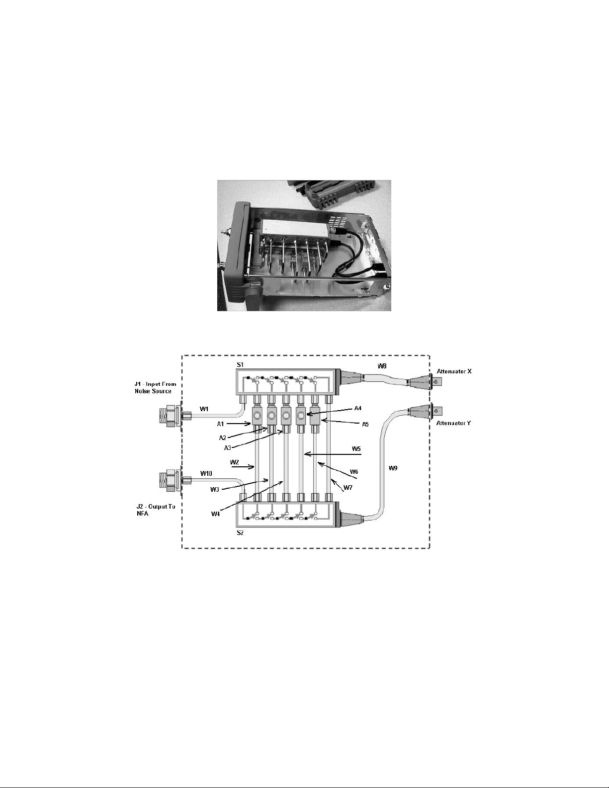
Description
Figure 1-2 shows the Noise Source Test Set with the cover removed.
Figure 1-3 shows the internal wiring and the reference designators of the parts
used in the Noise Source Test Set.
Figure 1-2 The Noise Source Test Set with Outer Cover Removed
Figure 1-3 The Noise Source Test Set Schematic Component Layout
12 Keysight N2002A User’s Guide
Page 15

Using the N2002A
Operation
Operation
This section refers to control operation of the Keysight N2002A Noise Source
Test Set. The Noise Source Test Set is controlled by a 11713A
attenuator/switch driver. The 11713A switch controlling settings are shown in
the Table 1-1. For more detailed operating instructions, refer to the Keysight
11713A Attenuator/Switch Driver Operating and Service Manual (Part number
11713-90023).
NOTE Connect the X and Y Drive cables between the rear panels of the Noise
Source Test Set and the 11713A Attenuator/Switch Driver.
Table 1-1 11713A Attenuator/Switch Driver Settings
Frequency Path (MHz) Attenuator X Attenuator Y Switches
1234567890
10 to <3000 xx
3000 to 6000 x x
<6000 to 12000 x x
>12000 to 18000 x x
>18000 to 26500 x x
Keysight N2002A User’s Guide 13
Page 16

Maintenance
N2002A Verification Test
Using the N2002A
Maintenance
Proper connector care is a vital part of the maintenance which should be
performed by the user. The life of the connector can be greatly extended by
following the general connector care practices outlined in Appendix G:,
“Caring for Connectors,” on page 111.
The verification test procedure involves confirming that the N2002A Noise
Source Test Set’s switch paths are functioning and the VSWR meets its typical
limit. Tab le 1-2 lists the typical VSWR limit and the switch positions on the
11713A.
Equipment Required
— Network analyzer frequency coverage from 10 MHZ to 26.5 GHz.
— Appropriate network analyzer calibration kits.
— Keysight 11713A Attenuator / Switch Driver.
— Viking cables for connection to 11713A.
Connections Required
Connect the Viking control cables from the rear of the 11713A
attenuator/switch driver to the rear of the N2002A Noise Source Test Set.
Connect Atten X on the 11713A to the Attenuator X on the N2002A and Atten
Y on the 11713A to Attenuator Y on the N2002A.
Table 1-2 Typical VSWR
Frequency Typical VSWR
Limit
10 MHz 1:1.05 0 On, 9 On
100 MHz 1:1.05 0 On, 9 On
1 GHz 1:1.05 0 On, 9 On
2 GHz 1:1.05 0 On, 9 On
3 GHz 1:1.05 0 On, 9 On
4 GHz 1:1.1 1 On, 5 On
5 GHz 1:1.1 1 On, 5 On
Switch
Positions
6 GHz 1:1.1 1 On, 5 On
7 GHz 1:1.15 3 On, 7 On
8 GHz 1:1.15 3 On, 7 On
14 Keysight N2002A User’s Guide
Page 17

Using the N2002A
Maintenance
Table 1-2 Typical VSWR
Frequency Typical VSWR
Limit
9 GHz 1:1.15 3 On, 7 On
10 GHz 1:1.15 3 On, 7 On
11 GHz 1:1.15 3 On, 7 On
12 GHz 1:1.15 3 On, 7 On
13 GHz 1:1.15 2 On, 6 On
14 GHz 1:1.15 2 On, 6 On
15 GHz 1:1.15 2 On, 6 On
16 GHz 1:1.15 2 On, 6 On
17 GHz 1:1.15 2 On, 6 On
18 GHz 1:1.15 2 On, 6 On
19 GHz 1:1.18 4 On, 8 On
20 GHz 1:1.18 4 On, 8 On
21 GHz 1:1.18 4 On, 8 On
Switch
Positions
22 GHz 1:1.18 4 On, 8 On
23 GHz 1:1.18 4 On, 8 On
24 GHz 1:1.18 4 On, 8 On
25 GHz 1:1.18 4 On, 8 On
26 GHz 1:1.18 4 On, 8 On
26.5 GHz 1:1.18 4 On, 8 On
Keysight N2002A User’s Guide 15
Page 18

Using the N2002A
General Specifications
General Specifications
NOTE This instrument is designed for indoor use only.
Table 1-3 Physical Dimension Specifications
Height 88.5 mm (3.5 inches)
Width 212.6 mm (8.5 inches)
Depth 348.3 mm (13.7 inches)
Weight 3.36 kg
Temperature Range
Humidity Range
Altitude Range
Operating: 0
Storage: -40
Operating: Up to 95% relative humidity to 40
Operating: To 4,600 meters
⁰C to +55 ⁰C
⁰C to +70 ⁰C
⁰C (non-condensing)
16 Keysight N2002A User’s Guide
Page 19

Using the N2002A
Replaceable Parts
Replaceable Parts
Table 1-4 and Table 1-5 lists the replaceable parts available for the Keysight
N2002A Noise Sources Test Set.
Table 1-4 Replaceable Parts
Reference Quantity Description Part Number
A1 1 18GHz - 26.5GHz Isolator N2002-80001
A2 1 12GHz - 18GHz Isolator N2002-80002
A3 1 6GHz - 12GHz Isolator N2002-80003
A4 1 3GHz - 6GHz Isolator N2002-80004
A5 1 3dB Attenuator 8493C
J1, J2 2 Bulkhead Connector 5062-1247
S1, S2 2 Multi-port Switch 8769K
W1 1 Semi rigid cable N2002-62003
W2, W3 2 Semi rigid cable N2002-62007
W4 1 Semi rigid cable N2002-62006
W5 1 Semi rigid cable N2002-62005
W6 1 Semi rigid cable N2002-62008
W7 1 Semi rigid cable N2002-62002
W8, W9 2 Viking cable N2002-62001
W10 1 Semi rigid cable N2002-62004
To order parts contact your local Keysight Technologies Sales and Service
Office. Refer to “Service” on page 19 for your local Sales and Service Offices
Table 1-5 Replaceable Parts
Description Quantity Part Number
Front Frame 1 N2002-20001
EMI Screen 1 N2002-20002
Front Panel 1 N2002-00003
Chassis 1 N2002-00005
Base Plate 1 N2002-00002
Switch Support 1 N2002-00001
Rear Panel 1 N2002-00004
Keysight N2002A User’s Guide 17
Page 20

Using the N2002A
Replaceable Parts
Table 1-5 Replaceable Parts
Description Quantity Part Number
Rear Bezel 1 E4418-20008
Cover 1 E4418-61027
Front Bumper 1 34401-86011
Rear Bumper 1 34401-86012
Handle 1 34401-45011
18 Keysight N2002A User’s Guide
Page 21
Service
Using the N2002A
Service
Contacting Keysight Technologies
When returning a Noise Source Test Set to Keysight Technologies for repair
send it to your nearest Sales and Service Office. These are listed in Table 1-6.
FAQs, instrument software updates, documentation, and other support
information can be accessed from this site.
To obtain servicing information or to order replacement parts, contact the
nearest Keysight office listed in Table 1-6. In any correspondence or telephone
conversations, refer to the instrument by its model number (N9030A) and full
serial number (ex. MY49250887). With this information, the Keysight
representative can quickly determine whether your unit is still within its
warranty period.
Table 1-6
By internet, phone, or fax, get assistance with all your test and measurement
needs.
Americas
Country Phone Number
Canada (877) 894 4414
Brazil 55 11 3351 7010
Mexico 001 800 254 2440
United States 1 800 829-4444
Asia Pacific
Country Phone Number
Australia 1 800 629 485
China 800 810 0189
Hong Kong 800 938 693
India 1 800 112 929
Japan 0120 (421) 345
Korea 080 769 0800
Keysight N2002A User’s Guide 19
Page 22
Using the N2002A
Service
Asia Pacific
Country Phone Number
Malaysia 1 800 888 848
Singapore 1 800 375 8100
Taiwan 0800 047 866
Other AP Countries (65) 6375 8100
Europe and Middle
Country Phone Number
Austria 0800 001122
Belgium 0800 58580
Finland 0800 523252
France 0805 980333
Germany 0800 6270999
Ireland 1800 832700
Israel 1 809 343051
Italy 800 599100
Luxembourg +32 800 58580
Netherlands 0800 0233200
Russia 8800 5009286
Spain 0800 000154
Sweden 0200 882255
Switzerland 0800 805353
Opt. 1 (DE)
Opt. 2 (FR)
Opt. 3 (IT)
United Kingdom 0800 0260637
20 Keysight N2002A User’s Guide
Page 23

Keysight Technologies
Noise Source Test Set
N2002A
2 The Noise Source Calibration Process and
Recommended Test Equipment
The Calibration Process
The calibration process consists of two performance verification tests:
— Excess Noise Ratio (ENR dB) test.
— Reflection Coefficient Magnitude and Phase tests.
The performance verification test procedures verify the electrical performance
to traceable standards of the following Keysight noise sources in accordance
with their published specification.
— 346A
— 346B
— 346C
— N4000A
— N4001A
— N4002A
NOTE The noise source calibration process also allows you to calibrate both
Keysight Technologies and other manufacturer’s noise sources operating
between 10.0 MHz and 26.5 GHz.
NOTE All tests are performed without access to the interior of the noise source.
21
Page 24

The Noise Source Calibration Process and Recommended Test Equipment
The Calibration Process
NOTE The noise source calibration process also allows you to calibrate additional
measurement frequency points other than the standard card inal points. The
measurement frequency points are determined by the frequency entries in the
ENR table.
The maximum measurement frequency/ENR pairs is 81.
Calibration Cycle
The noise sources require periodic verification of operational performance.
Under normal use and environmental conditions, a noise source is calibrated at
12 month intervals.
22 Keysight N2002A User’s Guide
Page 25

The Noise Source Calibration Process and Recommended Test Equipment
Test Descriptions
Test Descriptions
Excess Noise Ratio (ENR dB)
The Excess Noise Ratio (ENR) test is based on comparing the DUT test results
to a reference standard test resul ts. The reference standard is a calibrated
noise source with known ENR values. Measurements are taken on both the
reference standard and the DUT. The DUT ENR values are derived from these
resul ts.
These results verify that the noise source meets its published specification. The
specifications are provided in Table 2-1 on page 25.
The measurements are generally made at the cardinal frequencies points,
however, the NFA can allow up to 81 frequency/ENR pairs to be stored. The
suppled test records in the appendices only contain the cardinal frequency
points, therefore you need to create test record to increase this quantity.
NOTE The test should be performed within an environmental ambient temperature
of 296 ±1K (23° ±1°C).
Loading the Reference Standard’s ENR Data
Step 1. If you are using an SNS as a Reference Standard, the NFA uploads its ENR
data automatically. The NFA needs enabled to make this happen
automatically.
NOTE Further information on loading SNS ENR data, refer to the NFA User’s Guide.
Step 2. If you are using a 346x as a Reference Standard. you can use one of the
following methods:
—The A: drive.
—The C: drive.
— Create a file from the data supplied with the noise source, for example, the
certificate of calibration or the floppy disc.
— If you only want to calibrate the ENR data on a 346x noise source you can
use the ENR data on the noise source label.
Keysight N2002A User’s Guide 23
Page 26
The Noise Source Calibration Process and Recommended Test Equipment
Test Descriptions
Overview of the ENR Measurement Procedure
The process operates in the following method:
NOTE The ENR values of the reference standard (ENR1) are known.
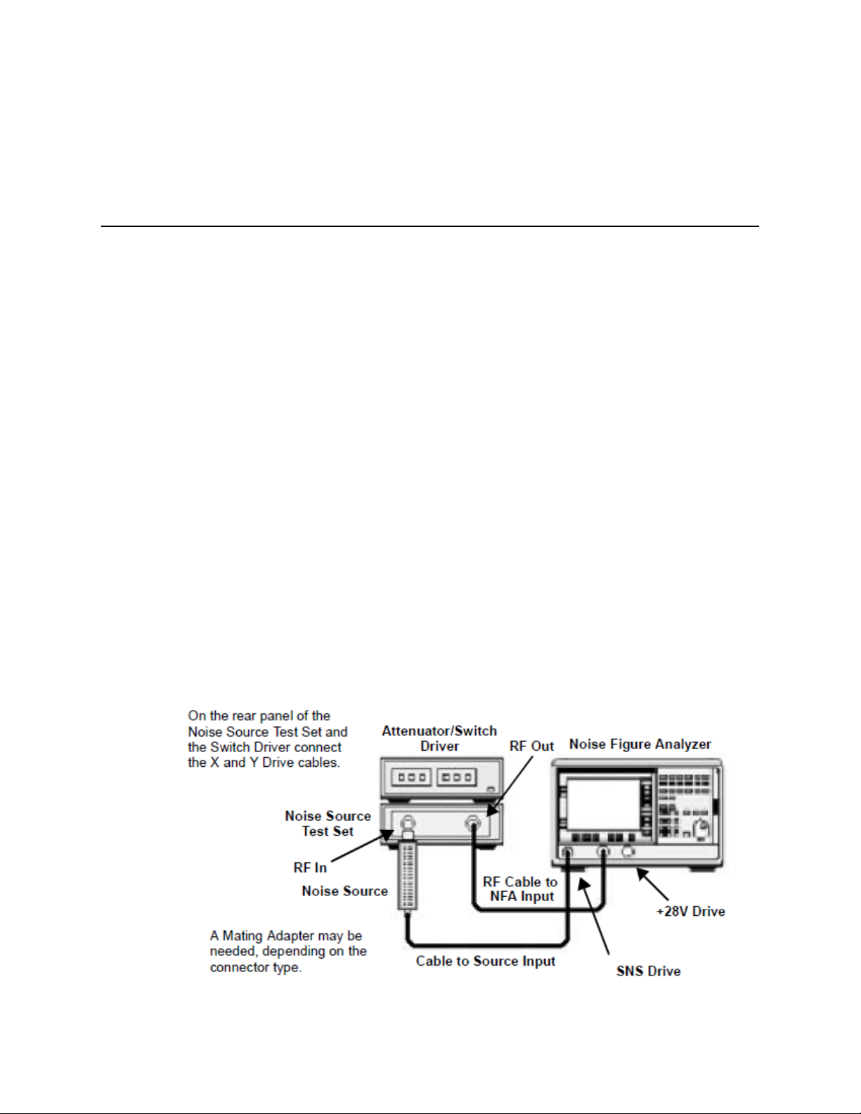
Step 1. Connect the test equipment together as shown in Figure 2-1.
Step 2. Set the test equipment to the measure the first frequency point.
Step 3. Measure a linear Y-Factor on the reference standard.
Step 4. On the Test Record note the result under the (Y
Step 5. Set the test equipment to the measure the next frequency point and repeat
the process until all the measurement points are complete.
Step 6. Remove the reference standard from the N2002A input and connect the DUT.
Step 7. Set the test equipment to the measure the first frequency point.
Step 8. Measure linear Y-Factor on the DUT.
Step 9. On the Test Record note the result under the (Y
Step 10. Repeat this process for the remaining measurement points.
Step 11. Using these measurement results, entering them in the equations, calculate
the ENR and the uncertainty values.
The Test Equipment Connection Diagrams for ENR Measurements
Figure 2-1 ENR Measurements
) column.
1
) column.
2
24 Keysight N2002A User’s Guide
Page 27

The Noise Source Calibration Process and Recommended Test Equipment
Test Descriptions
ENR Specifications
NOTE Specifications are valid at ambient temperature 23⁰ Celsius only (296 K).
Table 2-1 ENR Range for the Noise Sources
Instrument Model ENR Range
N4000A/346A 4.5 - 6.5 dB
N4001A/346B 14 - 16 dB
N4002A/346C 12 - 17 dB
Reflection Coefficient Magnitude and Phase
The Reflection Coefficient test measures the input magnitude and phase of the
noise source under test and verifies that it meets its published specification.
The specifications are provided in Table 2-2 on page 27 and Table 2-3 on
page 27. The tests are measured in the Source ON and OFF states.
The specified frequency ranges are swept for the maximum magnitude and
phase and the resultant maximum value is displayed on the VNA. The test also
measures the magnitude and phase at cardinal (pre-determined) frequency
points. These cardinal frequency points depend on the model and option being
tested.
The test equipment is connected together as shown in Figure 2-2 on page 26.
Overview of the Reflection Coefficient Magnitude and Phase
Measurement Procedure
NOTE The procedure requires network analyzer frequency range coverage from 10.0
MHz to 26.5 GHz. This procedures uses two VNAs, the 8753 is used to cover
the range 10.0 MHz to 3.0 GHz, and the 8722 is used to cover the range 3.0
GHz to 26.5 GHz.
The procedure operates in the following method:
Step 1. Calibrate the 8753 over the specified range, for example, 10.0 MHz to
1.5 GHz.
Step 2. Measure the DUT’s reflection coefficient, in an OFF and ON state, over the
specified range, for example, 10.0 MHz to 1.5 GHz.
Step 3. Note these resultant values on the Test Record.
Keysight N2002A User’s Guide 25
Page 28

The Noise Source Calibration Process and Recommended Test Equipment
Test Descriptions
Step 4. Measure the DUT’s reflection coefficient, in an OFF and ON state, at the
cardinal frequency points in the specified range.
Step 5. Note these resultant values on the Test Record.
Step 6. Repeat the Calibration and Measurement process using the 8753 over the
specified range, for example, 1.5 GHz to 3.0 GHz.
Step 7. Calibrate the 8722 over the specified range, for example, from 3.0 GHz to 7.0
GHz.
Step 8. Measure the DUT’s reflection coefficient, in an OFF and ON state, over the
specified range, for example, 3.0 GHz to 7.0 GHz.
Step 9. Note these resultant value on the Test Record.
Step 10. Measure the DUT’s reflection coefficient, in an OFF and ON state, at the
cardinal frequency points in the specified range.
Step 11. Note these resultant values on the Test Record.
Step 12. Repeat the Calibration and Measurement process using 8722 over the
specified range, for example, 3.0 GHz to 7.0 GHz
The Test Equipment Connection Diagrams for Reflection and Phase
Measurements
Figure 2-2 Reflection and Phase Measurements
26 Keysight N2002A User’s Guide
Page 29

The Noise Source Calibration Process and Recommended Test Equipment
Test Descriptions
Reflection and Phase Specifications
Table 2-2 Reflection Coefficient for 346x Noise Source
Frequency Range Model
346A 346B 346C
10.0 MHz to 30.0 MHz 0.13 0.13 0.11
30.0 MHz to 5.0 GHz 0.07 0.07 0.11
5.0 GHz to 18.0 GHz 0.11 0.11 0.11
18.0 GHz to 26.5 GHz ---------------- ---------------- 0.15
Table 2-3 Reflection Coefficient for the N400xA SNS
Frequency Range Model
N4000A N4001A N4002A
10.0 MHz to 1.5 GHz 0.02 0.07 0.10
1.5 GHz to 3.0 GHz 0.02 0.07 0.10
3.0 GHz to 7.0 GHz 0.06 0.09 0.10
7.0 GHz to 18.0 GHz 0.10 0.11 0.11
18.0 GHz to 26.5 GHz ---------------- ---------------- 0.15
Keysight N2002A User’s Guide 27
Page 30

The Noise Source Calibration Process and Recommended Test Equipment
Reference Standard Noise Source Selection
Reference Standard Noise Source Selection
The reference standard selection defines the measurement frequencies of both
the reference standard and the DUT. Both the reference standard and the DUT
must be measured at the same frequency points.
The accuracy of the DUT’s ENR measurement results is dependent on the
calibration accuracy of the reference standard. Also, a proportion of the DUT’s
measurement uncertainty is based on the reference standard’s measurement
uncertainty. Therefore, to maximize the measurement accuracy and minimize
the measurement uncertainty, a reference standard that has been calibrated by
a national standards laboratory is recommended.
NOTE
NOTE A Reference Standard’s ENR values are valid at calibration temperature only.
A Reference Standard’s uncertainty values are only valid at ambient
temperature 23°C ±1°C (296K).
More than one reference standard may be required for more accurate results.
Keysight Technologies recommend using the same type of reference standard
as the noise source being measured.
The ENR measurement process requires various adapters and cables. For more
accurate results Keysight Technologies recommend using high quality cables
and precision adapters. Care should be taken to ensure all cables and adapters
are specified for the frequency range in which they are used and that they are
in good electrical and mechanical condition.
Keysight Technologies noise sources can be used at non-standard (not
cardinal) frequency points by creating an ENR table containing the wanted
measurement frequency points. However, the ENR values and the ENR
uncertainty values of the reference standard must be manually interpolated
from the supplied data.
28 Keysight N2002A User’s Guide
Page 31

The Noise Source Calibration Process and Recommended Test Equipment
Recommended Test Equipment
Recommended Test Equipment
Table 2-4 Recommended Test Equipment for ENR Measurements
Equipment Description Critical Specifications for Equipment
Substitution
Noise Figure Analyzer No substitute available for SNS N8975A
Noise Source Test Set No substitute available N2002A
Attenuator/Switch Driver Compatible with 8768K multi-port switch 11713A
Attenuator/Switch Driver
Interconnect Cables (x2)
Standard Noise Source
(Dependant on DUT)
RF Cable 10MHz to 26.5GHz 3.5mm (M) to 3.5mm (M),
Adapter (NFA and Noise
Source Test Set)
Adapter (Dependant on DUT) DUT Connector Type: Adapter Type:
Compatible with 11713A Viking terminals 11764A
See “Reference Standard Noise Source Selection” on page 28
61 cm (24 in)
3.5mm Precision (F) to 3.5mm (F) 1250-1749
Type N (Male)
3.5mm (F) to Type N (F)
Type N (Female) 3.5mm (F) to Type N (M) 1250-1744
Recommended Model
11500E
1250-1745
APC 7
3.5mm (F) to APC 7
3.5mm (Male)
3.5mm (F) to 3.5mm (F)
BNC Lead Length 122cm (48”), Frequency 10MHz 10503A
SNS Interconnect Cable No substitute available 11730A
1250-1747
1250-1749
Keysight N2002A User’s Guide 29
Page 32

The Noise Source Calibration Process and Recommended Test Equipment
Recommended Test Equipment
Table 2-5 Recommended Test Equipment for ENR Measurements
Equipment Description Critical Specifications for
Equipment Substitution
Noise Figure Analyzer No substitute available for SNS N8975A
Vector Network Analyzer 1 10MHz to 3GHz 8753ES or 8753ET, opt 004
Vector Network Analyzer 2 3GHz to 18GHz or 26.5GHz 8722ES or 8722ET, opt 004
Calibration Kit 1 Connector: Type N
Impedance: 50 Ohm
Bandwid th: 10MHz to 3GHz
Calibration Kit 2 Connector: 3.5mm
Impedance: 50 Ohm
Bandwid th: 10MHz to 3GHz
Calibration Kit 3 Connector: 7 mm
Impedance: 50 Ohm
Bandwid th: 10MHz to 3GHz
Calibration Kit 4 Connector: Type N
Impedance: 50 Ohm
Bandwid th: 10.0 MHz to 18.0 GHz
Calibration Kit 5 Connector: 3.5 mm
Impedance: 50 Ohm
Bandwid th: 10.0 MHz to 18.0 GHz
Recommended Model
85032E
85033D
85031B
85054D
85052D
Calibration Kit 6 Connector: 7 mm
Impedance: 50 Ohm
Bandwid th: 10.0 MHz to 18.0 GHz
BNC Lead Length 122cm (48") 10503A
SNS Interconnect Cable No substitute available 11730A
85050D
30 Keysight N2002A User’s Guide
Page 33

Keysight Technologies
Noise Source Test Set
N2002A
3 Using the Manual Calibration Procedure
Introduction
Before You Start
Switch the test equipment on and let it warm up for at least one hour. Allow
the Noise Sources to stabilize at the ambient room temperature. Do not use a
noise source for one hour prior to performing the tests.
Read the rest of this section before you start any of the tests. Make a copy of
the Test Record of the models you are measuring.
Recording the Test Results
Test Records are provided in the Appendices for each Keysight noise source
model.
Keysight Technologies recommend that you make a copy of the Test Record,
recording the test results on the copy, and keep the copy for your calibration
test record. This record could prove valuable in tracking gradual changes in
test results over long periods of time.
Failure During the Test Procedures
If any of the tests fail and you suspect the unit requires repair. Please contact
your local Keysight Customer Sales and Service Office for replacement parts or
repair service information. Refer to
Service Offices.
“Service” on page 19 for your local Sales and
31
Page 34

Using the Manual Calibration Procedure
ENR Manual Procedure
ENR Manual Procedure
This procedure must be performed using the Test Records.
Before you start, enter the reference standard’s ENR values in the Standard
ENR1 column in the ENR Test Record and the reference standard’s uncertainty
values in the Standard ENR1 Uncertainty column in the Uncertainty Test
Record. These values are needed when calculating the DUT’s values using the
equations.
NOTE Refer to “Reference Standard Noise Source Selection” on page 28 for
information on this selection criteria.
CAUTION Ensure the correct torque settings are used at all times. Refer to Appendix G’s
Table 2 on page 126.
Step 1. Connect the equipment as shown in Figure 2-1. Depending on the reference
standard noise source selected, connect the equipment using either the SNS
interconnect cable or the BNC lead. Ensure the reference standard noise
source RF connector is the same type as the DUT and connect using the
preferred adapters listed in Table 2-4 on page 23.
Step 2. Ensure the Noise Figure Analyzer preset is set to factory settings.
a. Press the System key.
b. Press the More 1 of 3 menu key.
c. Press the Power On/Preset menu key.
d. Set the Power On to Power On (Preset) and Preset to Preset (Factory).
Step 3. Press Preset and wait for the preset routine to finish.
Step 4. Load the reference standard noise source ENR data.
Refer to Chapter 2’s “Loading the Reference Standard’s ENR Data” on
page 23 for information on this.
NOTE Do not calibrate the NFA. Ensure the NFA displays Uncorr.
Step 5. Select the display to meter mode.
a. Press the Format key.
b. Press the Format menu key.
c. Press the Meter menu key.
32 Keysight N2002A User’s Guide
Page 35

Using the Manual Calibration Procedure
ENR Manual Procedure
Step 6. Set the measured result to Y-Factor.
a. Press the Result key.
b. Press the Y-Factor menu key.
Step 7. Set the Y-Factor scale to linear units.
a. Press the Scale key.
b. Set the Units to Units (Linear).
Step 8. Set sweep to single.
a. Press the Sweep key.
b. Set the Sweep to Sweep Mode (Single).
Step 9. Set the frequency mode to fixed.
a. Press the Frequency/Points key.
b. Press the Freq Mode menu key.
c. Press the Fixed menu key.
Step 10. Set the averaging to 128 (or greater).
a. Press the Averaging/Bandwid th key.
b. Set the Averaging to Averaging (On).
c. Set the Average Mode to Average Mode (Sweep).
d. Press the Averages menu key and on the numeric key pad press 1, 2, 8,
followed by the Enter key.
Step 11. Alignment point.
Step 12. Set the frequency to 10.0 MHz.
a. Press the Frequency/Points key.
b. Press the Fixed Freq menu key and on the numeric key pad press 1, 0,
followed by the MHz menu key.
NOTE 10.0 MHz is the first frequency listed in the test record.
Step 13. Set the Attenuator/Switch Driver as follows:
a. Ensure LOCAL LED is on.
b. Set the switch to the required frequency path, for example, switches 9 and
0 are on, when measuring between 10.0 MHz and 3.0 GHz.
Keysight N2002A User’s Guide 33
Page 36

Using the Manual Calibration Procedure
ENR Manual Procedure
NOTE Refer to Table 1-1 on page 13 for Attenuator/Switch Driver settings for other
frequency ranges.
Step 14. On the NFA, press the Restart key, this restarts the NFA’s sweep.
Step 15. When the measurement is finished, in the Test Record, enter the Y-factor
reading next to the frequency point measured in the Standard Y
(Lin)
1
column.
Step 16. Repeat the steps for the remaining frequencies listed in the test record.
NOTE Set the Attenuator/Switch to the appropriate frequency path when changing
between frequency ranges.
Step 17. Connect the DUT as shown in Figure 2-1 on page 24. Depending on the DUT,
either use the SNS interconnect cable or the BNC cable.
Step 18. Set the frequency to 10.0 MHz
a. Press the Frequency/Points key.
b. Press the Fixed Freq menu key and on the numeric key pad press 1, 0,
followed by the MHz menu key.
NOTE 0.0 MHz is the first frequency listed in the test record.
Step 19. Set the Attenuator/Switch Driver as follows:
a. Ensure LOCAL LED is on.
b. Set the switch to the required frequency path, for example, switches 9 and
0 are on, when measuring between 10.0 MHz and 3.0 GHz.
Step 20. On the NFA, press the Restart key, this restarts the NFA’s sweep.
Step 21. When the measurement is finished, in the Test Record enter the Y-factor
reading next to the frequency point measured in the DUT Y
Step 22. Repeat the steps for the remaining frequencies listed in the test record.
(Lin) column.
2
NOTE Set the Attenuator/Switch to the appropriate frequency path when changing
between frequency ranges.
34 Keysight N2002A User’s Guide
Page 37

Using the Manual Calibration Procedure
ENR
2
10
Y21–()T
0
10
ENR
1
10
--------------
Y11–()
----------------------
×
×
T
0
------------------------------------------------------------------
log×=
UcENR
2
UcENR
1
()2UcSys()+
2
=
ENR Manual Procedure
Step 23. Using the Equation 3-1 and the results in the ENR Test Record, calculate the
value of each fixed frequency point for the DUT. Enter the ENR2
ENR
2
calculated values in the DUT ENR
Step 24. Complete the ENR Test Record results for the DUT and ensure the measured
values are within the published specification.
Step 25. Using the Equation 3-2 and the results in the Uncertainty Test Record,
calculate the ENR
DUT. Enter the U
Step 26. Complete the Uncertainty Test Record results for the DUT.
Step 27. If using an SNS series, transfer the data to the SNS using the procedure in the
section “Data Programming Process” on page 48.
The Equations
Equation 3-1 ENR Equation
(dB) column.
2
uncertainty value of each fixed frequency point for the
2
ENR2 calculated value in DUT ENR2 Uncertainty column.
c
The overall expanded uncertainty is calculated using the following equation for
each ENR
Noise Ratio (ENR dB) Test Records.
Equation 3-2 Uncertainty Equation
Keysight N2002A User’s Guide 35
value at each frequency point. See also the Appendixes for Excess
2
Page 38

Using the Manual Calibration Procedure
ENR Manual Procedure
Table 3-1 Terms Used in the Equations
Term Description
TO 290 Kelvin
DUT Device under test
ENR
ENR
Y
1
Y
2
U
C
1
2
ENR
1
Primary Standard Excess Noise Ratio value at each fixed frequency point
DUT calculated Excess Noise Ratio value at each fixed frequency point
Primary Standard measured linear Y-Factor at each fixed frequency point
DUT measured linear Y-Factor at each fixed frequency point
Primary Standard expanded uncertainty for each ENR value at each fixed
frequency point
ENR
U
C
2
DUT calculated expanded uncertainty for each ENR value at each fixed
frequency point
Sys Overall Test system uncertainty at each fixed frequency point
U
C
System Uncertainty Values
Table 3-2 is a summary of the uncertainty analysis calculations.
Table 3-2 Uncertainty Analysis Calculation Resul ts
Frequency (GHz) UcSys (± dB)
0.01 0.0785
0.10 0.0785
1.00 0.0905
2.00 0.0905
3.00 0.0726
4.00 0.0726
5.00 0.0726
6.00 0.0726
7.00 0.0800
8.00 0.0800
9.00 0.1076
10.00 0.1076
11.00 0.1076
36 Keysight N2002A User’s Guide
Page 39

Using the Manual Calibration Procedure
ENR Manual Procedure
Table 3-2 Uncertainty Analysis Calculation Resul ts
Frequency (GHz) UcSys (± dB)
12.00 0.1076
13.00 0.1211
14.00 0.1211
15.00 0.1211
16.00 0.1211
17.00 0.1211
18.00 0.1211
19.00 0.1491
20.00 0.1491
21.00 0.1491
22.00 0.1491
23.00 0.1491
24.00 0.1491
25.00 0.1491
26.00 0.1491
26.50 0.1491
Keysight N2002A User’s Guide 37
Page 40

Using the Manual Calibration Procedure
Reflection Coefficient Manual Procedure
Reflection Coefficient Manual Procedure
This test measures the Reflection Coefficient Magnitude and Phase of a noise
source from 10.0 MHz to 26.5 GHz. It may need two Vector Network Analyzers
(VNAs) to achieve the frequency range required.
Some noise sources have a break point which transgress the frequency range
of the Vector Network Analyzers. These have been identified in the Test
Records and you need to calibrate and test in these ranges.
NOTE The procedures refer to the key presses on an 8753ET. Other network
analyzers, for example, the 8753D may have different key labeling. Please
refer to the appropriate user’s guide for the relevant menu maps.
Calibrating the 8753
Use the following procedure to calibrate the 8753.
NOTE Ensure the noise source’s RF connector is the same type as the VNA and
connected using the preferred adapters listed in Table 2-5 on page 30.
NOTE The following example measures an N4000A. This model needs reflection and
phase measured over two frequency ranges, 10.0 MHz to 1.5 GHz and 1.5
GHz to 3.0 GHz. The model you are measuring may need different frequency
ranges measured, hence you need to confirm this by using your model’s
specifications and adjust the procedure accordingly.
Step 1. Factory Preset the Vector Network Analyzer.
a. Press the Preset key.
Step 2. Set the Active Channel to 1.
a. Press the Chan 1 key.
Step 3. Set the measurement mode to S11.
a. Press the Meas key.
b. Press the Reflection menu key.
Step 4. Set the 10.0 MHz start and 1.5 GHz stop frequencies.
a. Press the Start key.
b. Press the 1, 0, M/m keys.
38 Keysight N2002A User’s Guide
Page 41

Using the Manual Calibration Procedure
Reflection Coefficient Manual Procedure
c. Press the Stop key.
d. Press the 1, ., 5 , G/n keys.
Step 5. Set the measurement format to Polar.
a. Press Format key.
b. Press the Polar menu key.
Step 6. Set the number of measurement points to 401 points.
a. Press the Sweep Setup key.
b. Press the NUMBER of POINTS menu key.
c. Press the 4, 0, 1, x1 keys.
Step 7. Set the power level to –30dBm.
a. Press the Power key.
b. Press the -, 3, 0, x1 keys.
Step 8. If required, connect an adapter to connect the noise source under test to port
1 of the VNA.
NOTE The connector type (male/female) applies to the test port or adapter if fitted,
not the DUT’s connector.
Step 9. Select the appropriate calibration kit being used.
a. Press the Cal key
b. Press the CAL KIT menu key.
c. Press the SELECT CAL KIT menu key.
d. Select the calibration kit being used, for example, press the 85032B/E
menu key.
NOTE The calibration kit selection is dependent on the noise source under test.
e. Press the Return menu key.
Step 10. Select a S11 port calibration.
a. Press the Cal key.
b. Press the Calibrate Menu menu key.
c. Press the Reflection 1-Port menu key.
Keysight N2002A User’s Guide 39
Page 42

Using the Manual Calibration Procedure
Reflection Coefficient Manual Procedure
Step 11. Connect the Open to the test port (or, if fitted, the adapter) and perform the
open calibration.
a. Press the Opens menu key.
b. Select either Open (M) or Open (F) menu key.
c. When complete, press the Done Opens menu key.
Step 12. Connect the Short to the test port (or, if fitted, the adapter) and perform the
short calibration.
a. Press the Shorts menu key.
b. Select either Short (M) or Short (F) menu key.
c. When complete, press the Done Shorts menu key.
Step 13. Connect the Load to the test port (or, if fitted, the adapter) and perform the
load calibration.
a. Press the Loads menu key.
b. When complete, press Done 1-port CAL.
Step 14. Save the calibration.
a. Press the Save/Recall menu key.
b. Press the Save State menu key.
c. Note the Register the calibration data is saved in.
Measuring the DUT over 1st Frequency Range
Use the following procedure to measure the DUT.
NOTE The following example measures an N4000A. This model needs reflection and
phase measured over two frequency ranges, 10.0 MHz to 1.5 GHz and 1.5
GHz to 3.0 GHz using the 8753. The model you are measuring may need
different frequency ranges measured, hence you need to confirm this by
using your model’s specifications and adjust the procedure accordingly.
Step 1. Connect the equipment as shown in Figure 2-2 on page 26.
NOTE Ensure the VNA’s RF connector is the same type as the DUT and connected
using the preferred adapters listed in Table 2-5 on page 30.
Step 2. Ensure the VNA display format is set to Polar.
a. Press the Meas key. (This returns the format to Polar.)
40 Keysight N2002A User’s Guide
Page 43

Using the Manual Calibration Procedure
Reflection Coefficient Manual Procedure
Step 3. On the VNA, set the averaging to 16.
a. Press the Avg key.
b. Press the Averaging to Averaging (On).
c. Press the Averaging Factor menu key.
d. Press the 1, 6, x1 keys.
Step 4. Ensure the Noise Figure Analyzer preset is set to factory settings.
a. Press the System key.
b. Press the More 1 of 3 menu key.
c. Press the Power On/Preset menu key.
d. Set the Power On to Power On (Preset) and Preset to Preset (Factory).
Step 5. On the NFA, press Preset and wait for the routine to finish.
Step 6. On the NFA, set the sweep to single and wait for the sweep to finish.
a. Press the Sweep key.
b. Set the Sweep to Sweep Mode (Single).
Step 7. On the NFA, set the noise source to off.
a. Press the Sweep key.
b. Press the Manual Meas menu key.
c. Press the Manual State (On) menu key.
d. Press the Noise Source Off menu key.
Step 8. n the VNA, press the Marker Search key.
Step 9. On the VNA, press the Search: Max menu key.
Step 10. Record the Source OFF maximum displayed reflection magnitude and phase
values on the Test Record.
Step 11. On the NFA, press the Noise Source On menu key.
Step 12. On the VNA, press the Marker Search key.
Step 13. On the VNA, press the Search: Max menu key.
Step 14. Record the Source ON maximum displayed reflection magnitude and phase
values on the Test Record.
Step 15. On the VNA, set the marker to 10.0 MHz.
ess the Marker key.
a. Pr
ess the 1, 0, M/m keys.
b. Pr
Keysight N2002A User’s Guide 41
Page 44

Using the Manual Calibration Procedure
Reflection Coefficient Manual Procedure
Step 16. Record the Source ON maximum displayed reflection magnitude and phase
values on the Test Record to 10.0 MHz.
Step 17. Repeat the steps for the 100.0 MHz and 1.0 GHz cardinal frequency points
listed in the Test Record and note their values on the test record.
Step 18. On the NFA, press the Noise Source Off menu key.
Step 19. Recording the Source OFF maximum displayed reflection magnitude and
phase values on the test record at 1.0 GHz.
Step 20. Repeat the step for the 100.0 MHz and 10.0 MHz cardinal frequency points
listed in the Test Record and note their values on the Test Record.
Step 21. Ensure all the measured values are within the published specification.
NOTE Repeat the calibration and measurement procedure for the other frequency
ranges as applicable.
Calibrating the 8722
Use the following procedure to calibrate the 8722.
NOTE The following example measures an N4000A. This model needs reflection and
phase measured over two frequency ranges, 3.0 GHz to 7.0 GHz and 7.0 MHz
to 18.0 GHz using the 8722. The model you are measuring may need different
frequency ranges measured, hence you need to confirm this by using your
model’s Test Records and adjust the procedure accordingly.
NOTE Ensure the noise source’s RF connector is the same type as the DUT and
connected using the preferred adapters listed in Table 2-5 on page 30.
Step 1. Factory Preset the Vector Network Analyzer.
a. Press the Preset key.
Step 2. Set the Active Channel to 1.
a. Press the Chan 1 key.
Step 3. Set the measurement mode to S11.
a. Press the Meas key.
b. Press the Reflection menu key.
Step 4. Set the 3.0 GHz start and 7.0 GHz stop frequencies.
42 Keysight N2002A User’s Guide
Page 45

Using the Manual Calibration Procedure
Reflection Coefficient Manual Procedure
a. Press the Start key.
b. Press the 3, ., 0, G/n keys.
c. Press the Stop key.
d. Press the 7, ., 0 , G/n keys.
Step 5. Set the measurement format to Polar.
a. Press Format key.
b. Press the Polar menu key.
Step 6. Set the number of measurement points to 401 points.
a. Press the Sweep Setup key.
b. Press the NUMBER of POINTS menu key.
c. Press the 4, 0, 1, x1 keys.
Step 7. Set the power level to –30dBm.
a. Press the Power key.
b. Press the -, 3, 0, x1 keys.
Step 8. If required, connect an adapter to connect the noise source under test to port
1 of the VNA.
NOTE The connector type (male/female) applies to the test port or adapter if fitted,
not the DUT’s connector.
Step 9. Select the appropriate calibration kit being used.
a. Press the Cal key
b. Press the CAL KIT menu key.
c. Press the SELECT CAL KIT menu key.
d. Select the calibration kit being used, for example, press the 85032B/E
menu key.
NOTE The calibration kit selection is dependent on the noise source under test.
e. Press the Return menu key.
Step 10. Select a S11 port calibration.
a. Press the Cal key.
Keysight N2002A User’s Guide 43
Page 46

Using the Manual Calibration Procedure
Reflection Coefficient Manual Procedure
b. Press the Calibrate Menu menu key.
c. Press the Reflection 1-Port menu key.
Step 11. Connect the Open to the test port (or, if fitted, the adapter) and perform the
open calibration.
a. Press the Opens menu key.
b. Select either Open (M) or Open (F) menu key.
c. When complete, press the Done Opens menu key.
Step 12. Connect the Short to the test port (or, if fitted, the adapter) and perform the
short calibration.
a. Press the Shorts menu key.
b. Select either Short (M) or Short (F) menu key.
c. When complete, press the Done Shorts menu key.
Step 13. Connect the Load to the test port (or, if fitted, the adapter) and perform the
load calibration.
a. Press the Loads menu key.
b. When complete, press Done 1-port CAL.
Step 14. Save the calibration.
a. Press the Save/Recall menu key.
b. Press the Save State menu key.
c. Note the Register the calibration data is saved in.‘
Measuring the DUT over 1st Frequency Range
Use the following procedure to measure the DUT.
NOTE The following example measures an N4000A. This model needs reflection and
phase measured over two frequency ranges, 3.0 GHz to 7.0 GHz and 7.0 MHz
to 18.0 GHz using the 8722. The model you are measuring may need different
frequency ranges measured, hence you need to confirm this by using your
model’s Test Records and adjust the procedure accordingly.
NOTE Ensure the noise source’s RF connector is the same type as the DUT and
connected using the preferred adapters listed in Table 2-5 on page 30.
Step 1. Connect the equipment as shown in Figure 2-2 on page 26.
44 Keysight N2002A User’s Guide
Page 47

Using the Manual Calibration Procedure
Reflection Coefficient Manual Procedure
Step 2. Ensure the VNA display format is set to Polar.
a. Press the Meas key. (This returns the format to Polar.)
Step 3. On the VNA, set the averaging to 16.
a. Press the Avg key.
b. Press the Averaging to Averaging (On).
c. Press the Averaging Factor menu key.
d. Press the 1, 6, x1 keys.
Step 4. Ensure the Noise Figure Analyzer preset is set to factory settings.
a. Press the System key.
b. Press the More 1 of 3 menu key.
c. Press the Power On/Preset menu key.
d. Set the Power On to Power On (Preset) and Preset to Preset (Factory).
Step 5. On the NFA, press Preset and wait for the routine to finish.
Step 6. On the NFA, set the sweep to single and wait for the sweep to finish.
a. Press the Sweep key.
b. Set the Sweep to Sweep Mode (Single).
Step 7. On the NFA, set the noise source to off.
a. Press the Sweep key.
b. Press the Manual Meas menu key.
c. Press the Manual State (On) menu key.
d. Press the Noise Source Off menu key.
Step 8. On the VNA, press the Marker Search key.
Step 9. On the VNA, press the Search: Max menu key.
Step 10. Record the Source OFF maximum displayed reflection magnitude and phase
values on the Test Record.
Step 11. On the NFA, press the Noise Source On menu key.
Step 12. On the VNA, press the Marker Search key.
Step 13. On the VNA, press the Search: Max menu key.
Step 14. Recor
d the Sour
ce ON maximum displayed reflection magnitude and phase
values on the Test Record.
Step 15. On the VNA, set the marker to 3.0 GHz.
Keysight N2002A User’s Guide 45
Page 48

Using the Manual Calibration Procedure
Reflection Coefficient Manual Procedure
a. Press the Marker key.
b. Press the 3, ., 0, G/n keys.
Step 16. Record the Source ON maximum displayed reflection magnitude and phase
values on the Test Record at 3.0 GHz.
Step 17. Repeat the steps for the 4.0 GHz, 5.0 GHz, 6.0 GHz, and 7.0 GHz cardinal
frequency points listed in the Test Record and note their values on the Test
Record.
Step 18. On the NFA, press the Noise Source Off menu key.
Step 19. Recording the Source OFF maximum displayed reflection magnitude and
phase values on the test record at 7.0 GHz.
Step 20. Repeat the step 13 for the 4.0 GHz, 5.0 GHz, 6.0 GHz, and 7.0 GHz cardinal
frequency points listed in the Test Record and note their values on the Test
Record.
Step 21. Ensure all the measured values are within the published specification.
NOTE Repeat the calibration and measurement procedure for the other frequency
ranges as applicable.
46 Keysight N2002A User’s Guide
Page 49

Keysight Technologies
Noise Source Test Set
N2002A
4 Manually Programming Data into an Keysight Smart
Noise Source
Introduction
This section describes the procedure used to program data into an Keysight
N400xA Series Smart Noise Sources.
WARNING This procedure is performed at the your own risk. Failure to correctly
follow this procedure may render the noise source inoperative.
Equipment Required
The following equipment is required to program data into an Keysight N400xA
smart noise source series:
— An Keysight NFA Series Noise Figure Analyzer.
— An 11730A Noise Source cable to connect the noise source to the NFA.
— A 3.5 inch formatted floppy disk.
—A personal computer.
47
Page 50

Manually Programming Data into an Keysight Smart Noise Source
Data Programming Process
Data Programming Process
The new calibration data to be programmed into the smart noise source must
be in the correct format. Formatting the data can only be performed on a PC.
When the data is in the correct format it is copied to the NFA, and then
programmed into the smart noise source
Formatting the Data
An example data file is shown in page 51 and shows the cardinal frequency
points of an 18.0 GHz SNS. This example file can be used as a template for
formatting the data to be programmed into the smart noise source.
Alternatively, the data currently contained into the SNS can be copied to a PC
and used as a template, using the following procedure.
Step 1. Connect the smart noise source to the NFA.
Step 2. Confirm the Source Preference is set to SNS. To do this follow Step 3 through
to Step 5.
Step 3. Press the ENR key.
Step 4. Press the SNS Setup menu key.
Step 5. Ensure Preference is set to Preference (SNS).
Step 6. Save the data from the smart noise source by pressing File key.
Step 7. Press the Save menu key.
Step 8. Press the ENR menu key.
Step 9. Press the SNS menu key.
Step 10. Using the Alpha Editor, name the file, for example, template.enr.
Step 11. Transfer this template file to your PC from the floppy disk.
Step 12. Save a copy of this file in your PC.
The file can be edited in an ASCII text editor, for example, Notepad.
Editing the Data File
There are only certain fields in the data file which you should edit. The example
data file shown in page 51, shows the following information:
— The NFA model.
— The NFA serial number.
— The NFA firmware revision.
— The date that the data file was created.
— The serial number of the smart noise source.
48 Keysight N2002A User’s Guide
Page 51

Manually Programming Data into an Keysight Smart Noise Source
Data Programming Process
— The model number of the smart noise source.
— The calibration date.
— The temperature the calibration was carried out under.
— The humidity the calibration was carried out under.
The fields that are edited in the data file are:
— [Caldate 20010227] - Calibration Date (yyyymmdd)
— [Temperature 23.000000] - Temperature the calibration was performed at.
— [Humidity 30.000000] - Humidity the calibration was performed at.
NOTE Do not change the value shown in the field marked [Current xxxx], as this
affects the smart noise source’s performance.
The other fields in the data file contain the frequency points, ENR (dB) values,
ENR uncertainties, and Reflection and Phase values. The frequency points can
be added or removed as required. The maximum number of points is 81.
NOTE Each field must have a data entry, for this process to work correctly.
Programming the Data File into the SNS
Program the data file into the SNS use the following procedure.
Step 1. Save the new data file as ‘writesns.enr’ to a floppy disk.
Step 2. Insert the floppy disk in the NFA’s floppy drive.
Step 3. Press the System key.
Step 4. Press the More 1 of 3 menu key.
Step 5. Press the More 2 of 3 menu key.
Step 6. Press the Service menu key.
Step 7. Enter the password by pressing -, 2, 0,1, 0 on the numeric key pad.
Step 8. Press the Enter key.
Step 9. Press the Service menu key.
Step 10. Press the More 1 of 2 menu key.
Step 11. Press the Write to SNS menu key and follow the instructions on the display.
Keysight N2002A User’s Guide 49
Page 52

Manually Programming Data into an Keysight Smart Noise Source
Data Programming Process
Verifying the SNS was Programmed
To check if the SNS was programmed successfully, do the following:
Step 1. Press the ENR key.
Step 2. Press the ENR Table menu key.
Step 3. Press the Fill Table From SNS menu key.
The ENR Table should show the correct data.
50 Keysight N2002A User’s Guide
Page 53

Manually Programming Data into an Keysight Smart Noise Source
Example
Example
This example is an SNS ENR file saved to a diskette:
NOTE The values shown in the example are representative of their position in the
file.
# ENR Data File
# Created by N8975A NFA Series Noise Figure Analyzer
# Serial Number GB40390135 Firmware Revision A.01.01
# 13:37:07 Mar 28, 2002
# Format is: Frequency (Hz), ENR (dB), ENR Unc (dB), # On Refl.Mag
(lin),
# On Refl.Phase (deg), Off Refl.Mag (lin), # Off Refl.Phase (deg),
On Refl.Mag Unc (lin),
# On Refl.Phase Unc (deg), Off Refl.Mag Unc (lin), # Off Refl.Phase
Unc (deg)
[Filetype ENR]
[Version 1.1]
[Serialnumber US411130226][Model N4001A]
[Caldate 20000727]
[Trackingnum 10]
[Temperature 23.000000]
[Humidity 63.000000]
[Current 2688]
10000000,15.281,0.193,0.0450,-136.0,0.0450,-136.0,0.0030, -6.0,
0.0070, +6.0
100000000, 15.291, 0.190, 0.0358, +168.0, 0.0358, +168.0, 0.0040,
+4.6, 0.0050, -4.6
1000000000, 15.118, 0.151, 0.0398, +39.6, 0.0398, +39.6, 0.0100,
+4.5, 0.0067, +1.5
2000000000, 14.999, 0.168, 0.0377, 0.168, 0.0377, -85.7, 0.0056,
+0.9, 0.0086, +1.9
3000000000, 14.879, 0.172, 0.0267, +150.6, 0.0267, +150.6, 0.0080,
-9.2, 0.0090, -1.2
4000000000, 14.795, 0.173, 0.0130, -18.1, 0.0130, -18.1, 0.0013,
+16.0, 0.0063, +10.0
5000000000, 14.818, 0.179, 0.0359, +169.5, 0.0359, +169.5, 0.0024,
-9.3, 0.0035, -0.3
6000000000, 14.846, 0.181, 0.0556, +63.7, 0.0556, +63.7, 0.0041,
+10.3, 0.0067, -4.3
7000000000, 14.895, 0.180, 0.0430, -37.0, 0.0430, -27.0, 0.0079,
Keysight N2002A User’s Guide 51
Page 54

Manually Programming Data into an Keysight Smart Noise Source
Example
-2.3, 0.0049, -2.3
8000000000, 15.016, 0.198, 0.0232, -160.3, 0.0232, -160.3, 0.0091,
-3.8, 0.0053, -1.8
9000000000, 15.134, 0.201, 0.0122, +71.4,0.0122, +71.4, 0.0037,
+17.3, 0.0057, +7.3
10000000000, 15.253, 0.194, 0.0080, +116.2, 0.0080, +116.2, 0.0048,
-1.4, 0.0056, -5.4
11000000000, 15.249, 0.243, 0.0241, +65.7, 0.0241, +65.7, 0.0059,
+1.5, 0.0049, +44.5
12000000000, 15.349, 0.240, 0.0196, +8.8, 0.0196, +8.8, 0.0057,
+3.2, 0.0077, +2.2
13000000000, 15.383, 0.188, 0.0217, -5.4, 0.0217, -5.4, 0.0062,
-6.9, 0.0045, -1.9
14000000000, 15.355, 0.178, 0.0228, -66.6, 0.0228, -66.6, 0.0075,
+11.2, 0.0065, +1.2
15000000000, 15.367, 0.187, 0.0141, +141.6, 0.0141, +141.6, 0.0036,
-3.2, 0.0029, -1.2
16000000000, 15.421, 0.182, 0.0251, +6.4, 0.0251, +6.4, 0.0030,
+7.2, 0.0042, -1.21
52 Keysight N2002A User’s Guide
Page 55

Keysight Technologies
Noise Source Test Set
N2002A
5 Using the Keysight N2002A Noise Source
Demonstration Software
This chapter describes how to setup and configure the Keysight N2002A Noise
Source Demonstration Software.
Getting Started
This section describes the software requirements, the system requirements,
and the required directory structure to setup and configure the Keysight
N2002A Noise Source Demonstration Software.
The Keysight N2002A Noise Source Demonstration Software is written in
Keysight VEE Pro Version 6.0 and is supplied as an VEE Pro Version 6.0 file
(.vee) and as an VEE Run Time executable file (.vxe). The Keysight VEE Run
Time executable file (.vxe) can not be modified. The Keysight VEE file need to
have VEE Pro 6.0 installed before it can run. The file can be modified. The
Keysight VEE Run Time Executable file requires VEE Pro 6.0 Run Time
environment. The Keysight VEE Run Time executable file can not be modified.
NOTE The Keysight N2002A Noise Source Demonstration Software is supplied ‘as
is’. Keysight Technologies offers no support or warranty in the event of user
modification and any problems arising as a result of user modification.
Additional Software Requirements
The IO libraries must be installed to allow instrument control.
System Requirements
The system requirements to run the Keysight N2002A Noise Source
Demonstration Software are:
— PC with 120 MHz Pentium processor (266 MHz Pentium II or higher
recommended)
— Microsoft Windows 2000 or Windows XP
53
Page 56
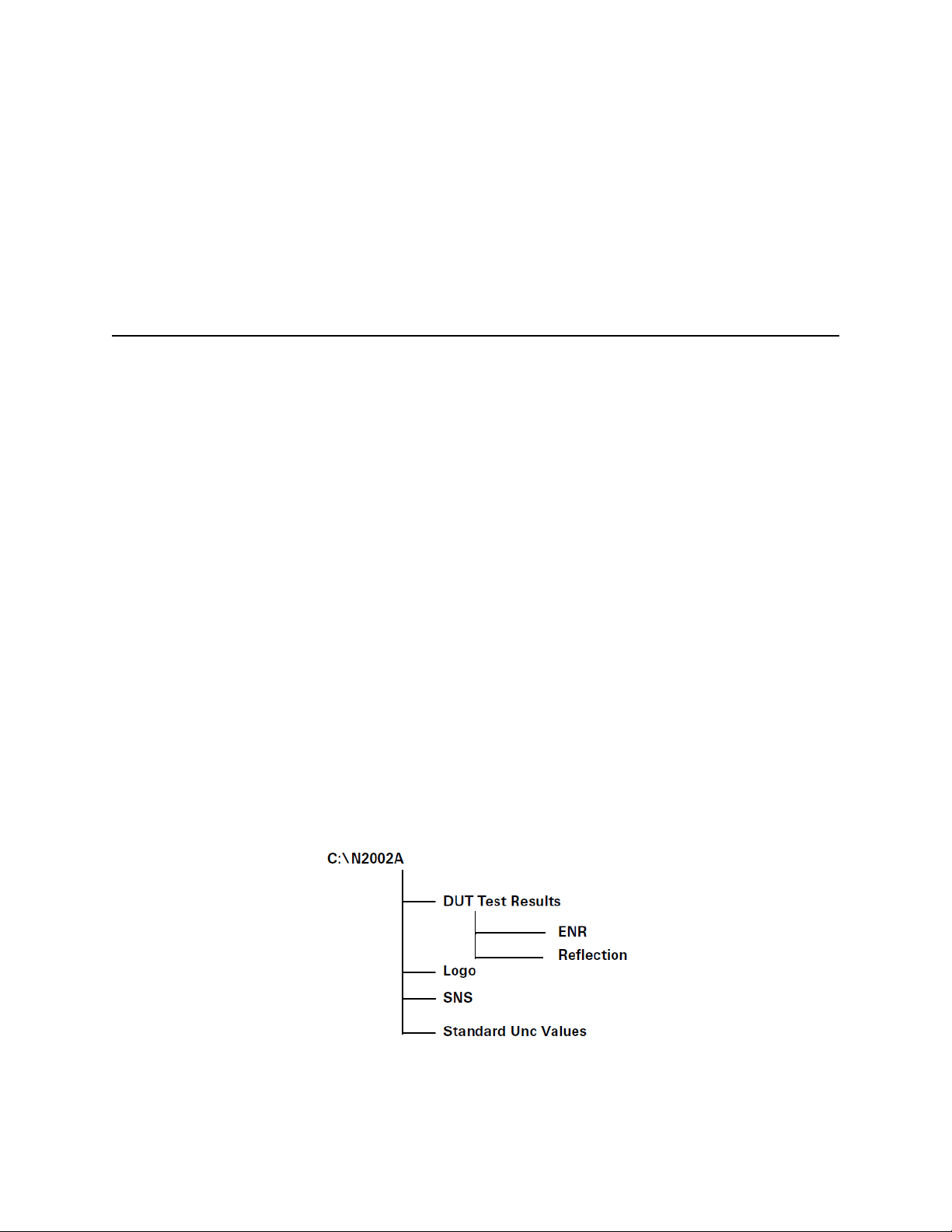
Using the Keysight N2002A Noise Source Demonstration Software
Getting Started
— 64 MB RAM with Windows 2000/XP
— GPIB interface card (Keysight 82350A) or Keysight 82357A USB/GPIB
interface.
—IO Libraries
NOTE Keysight Technologies recommends that the System standby feature on your
Windows OS is disabled. This option is found under the power options in the
Control Panel.
Test Equipment
In Chapter 2, “The Noise Source Calibration Process and Recommended Test
Equipment” there are tables listing the recommended equipment.
Limited substitution is supported when using the Keysight N2002A Noise
Source Demonstration Software.
The Keysight N2002A Noise Source Demonstration Software was written
specifically for the following Keysight test equipment:
ENR
Measurement:
— N8975A Noise Figure Analyzer
— N2002A Noise Source Test Set
— 11713A Attenuator/Switch Driver
Directory Structure Required
Figure 5-1 shows the required directory structure you must create on the C:
drive of the computer. This allows you use to run the Keysight N2002A Noise
Source Demonstration Software. This is required for both the versions of the
software.
Figure 5-1 Directory Structure
54 Keysight N2002A User’s Guide
Page 57
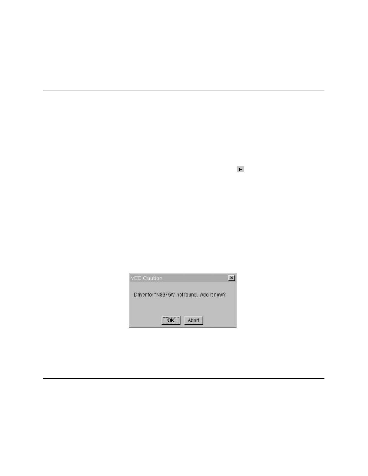
Using the Keysight N2002A Noise Source Demonstration Software
Getting Started
NOTE Copy the files named agilent.gif and spark.gif from the logo directory
on the N2002A CD to the logo directory on the computer used to run the
Keysight N2002A Noise Source Demonstration Software.
Opening the VEE Pro 6.0 (.vee) Software File
To start the Keysight N2002A Noise Source Demonstration Software you need
to open the Keysight VEE Pro 6.0 program. To do this do the following:
Step 1. Open the file by clicking File Open from the CD.
Step 2. Select the file name (or use the default).
Step 3. Select the Debug/Run or the Play button icon ( ) or Cntl-G.
Figure 5-5 on page 61 shows the Main Start Up window.
Setting up the Address Drivers
On initial opening of the Keysight N2002A Noise Source Demonstration
Software the GPIB controlled test equipment needs configured with their
address drivers. This is explained in the following procedure:
Step 1. The initial time the program is ran a Caution, as shown in Figure 5-2, is
displayed informing you that a driver for the N8975A can not be found.
Figure 5-2 A VEE Driver Caution
NOTE If you do not have the required equipment connected when the Caution is
displayed, either enter a GPIB address for the equipment, or allow the
address to remain set at 0.
Step 2. To add a driver, click OK to display the Instrument Properties box. You need to
enter the address of the N8975A.
This is the only data you need to enter.
Keysight N2002A User’s Guide 55
Page 58

Using the Keysight N2002A Noise Source Demonstration Software
Getting Started
Step 3. The address can be a three or four digit number and consists of the logical
unit of the GPIB card plus the address of the N8975A. Table 5-1 provides a list
of default instrument address settings.
Step 4. Click OK when the correct address has been entered in the Instrument
Properties box.
Table 5-1 Default Addresses
Instrument GPIB Address GPIB Card Address
N8975A 08 708
Switch 11713A 28 728
8722 24 724
8753 16 716
Step 5. Another Caution is displayed informing you that a driver for the 11713A can
not be found. Enter the correct GPIB address.
Step 6. Save the file using the Save in VEE window when the file loading in complete.
Configuring the VEE Pro 6.0 Run Time File IO
Use the procedure to configure the IO.
Step 1. Select the Keysight VEE Pro 6.0 Run Time Config program.
Step 2. Select IO Configuration.
Step 3. Use Instrument.
Step 4. Add to create an entry for each piece of equipment. Use the instrument
names shown in Tab le 5-1 and enter the appropriate GPIB address.
Before running the Keysight N2002A Noise Source Demonstration Software
Before you run the Keysight N2002A Noise Source Demonstration Software
ensure the test equipment is correctly connected. If a GPIB connection fails to
establish a warning appears on the display, Figure 5-3 shows a typical
warning. The equipment connections are shown in Figure 2-1 on page 24 for
ENR Measurement. To perform an ENR Measurement the only equipment
needed is the N8975A, 11713A, and N2002A.
56 Keysight N2002A User’s Guide
Page 59
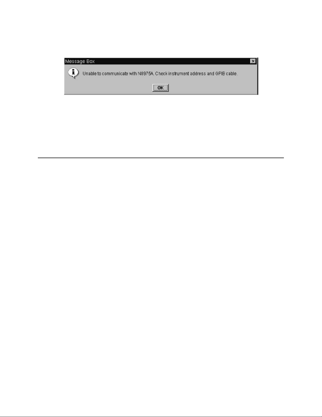
Using the Keysight N2002A Noise Source Demonstration Software
Getting Started
Figure 5-3 Communication Warning!
NOTE Ensure the reference standard’s ENR table is loaded into the N8975A before
running the software. See Chapter 2’s “Loading the Reference Standard’s
ENR Data” on page 23 for more information on doing this.
If the reference standard is changed while you are running the software,
ensure that the correct reference standard’s ENR table is loaded into the NFA.
Keysight N2002A User’s Guide 57
Page 60

Using the Keysight N2002A Noise Source Demonstration Software
The ENR Measurement Procedure
The ENR Measurement Procedure
The following procedure explains how to make an ENR measurement. Each
step in the procedure is explained in greater detail in the referenced section. In
the pdf file of this manual, each of the referenced sections has a link to return
you to this procedure.
To start the procedure you must have the Main Start Up Window displayed,
this is shown is Figure 5-5 on page 61.
Step 1. Enter the Test Details. The entered details are shown on the Measurement
displays.
The section, “Test Details” on page 62 explains this in detail.
Step 2. Select ENR Measurement on the Main Start Up Window.
The section, “ENR Measurement” on page 63 explains this in detail.
Step 3. Select a Measurement Reference Standard.
The section, “Selecting and Measuring the Reference Standard” on page 64
explains this in detail.
Step 4. Select the Reference Standard Type.
The section, “Selecting the Reference Standard” on page 66 explains this in
detail.
Step 5. Enter ENR data for the selected Reference Standard.
Chapter 2’s section, “Loading the Reference Standard’s ENR Data” on
page 23 explains this in detail.
Step 6. Enter Uncertainty data of selected Reference Standard.
The section, “Selecting Reference Standard Measurement Uncertainty Data”
on page 69 explains this in detail.
Step 7. Measure the Reference Standard.
The section, “Performing Reference Standard Measurement” on page 69
explains this in detail.
Step 8. On the display are both items green?
If Yes, proceed to the next step. If No, repeat the steps again.
Step 9. Select the type of DUT to be measured.
The section, “Selecting the DUT to be Measured” on page 71 explains this in
detail.
Step 10. Measure the DUT.
The section, “Measuring a DUT” on page 73 or “Making Multi Measurement
on a DUT” on page 77 explains this in detail.
58 Keysight N2002A User’s Guide
Page 61

Using the Keysight N2002A Noise Source Demonstration Software
The ENR Measurement Procedure
Step 11. Save the results.
Step 12. Copy data to SNS. The section, “Copying Data to SNS” on page 75 explains
this in detail.
Keysight N2002A User’s Guide 59
Page 62
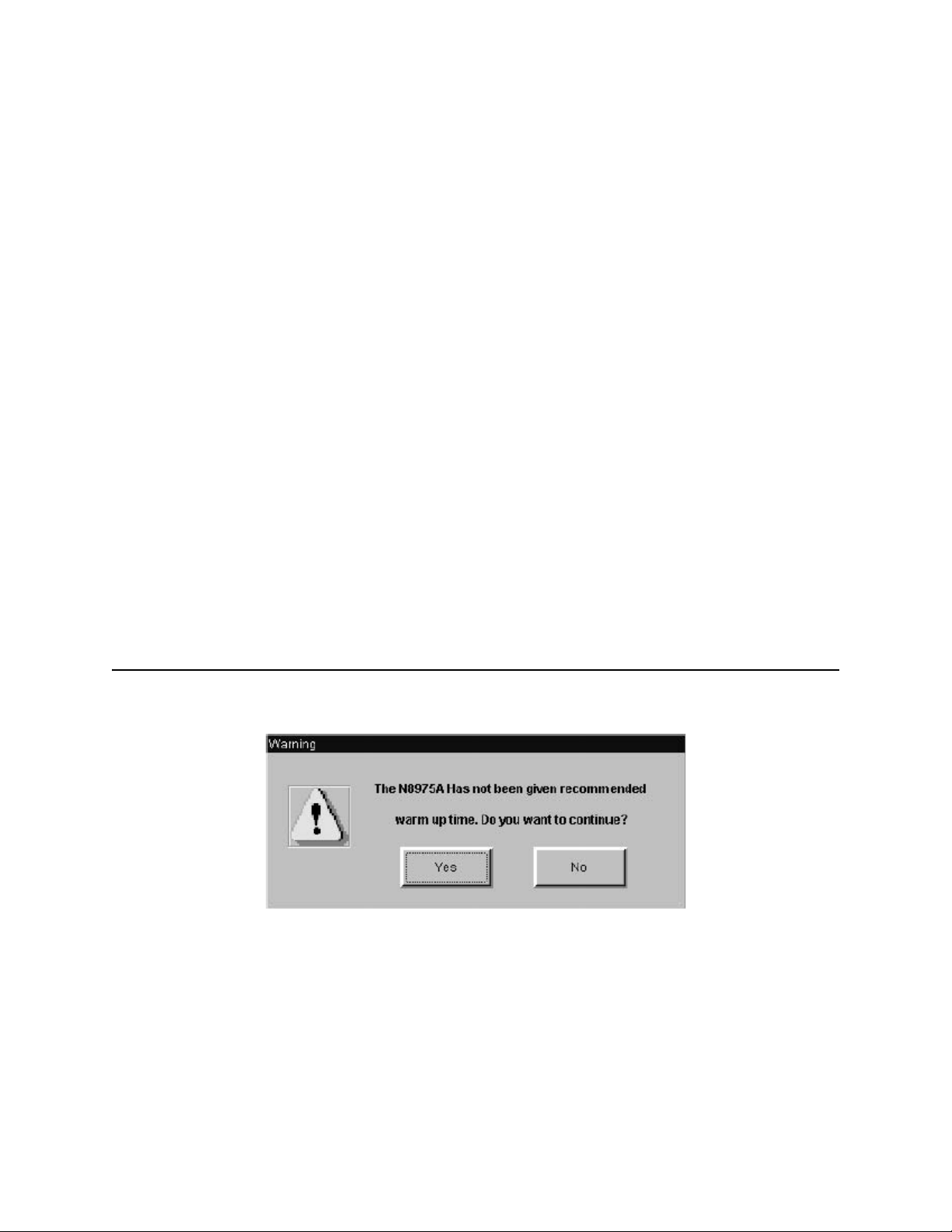
Using the Keysight N2002A Noise Source Demonstration Software
Running the Keysight N2002A Noise Source Demonstration Software
Running the Keysight N2002A Noise Source Demonstration Software
To start the Keysight VEE Pro 6.0 file use the Run or Start from within VEE Pro
6.0.
The Keysight VEE Pro 6.0 run time file is started using windows explorer.
When the Keysight N2002A Noise Source Demonstration Software is running
the main window shown Figure 5-5 on page 61 is visible.
Ensure all the test equipment is powered up and allow to warm up for one
hour. You also need to run the N8975A YTF Alignment routine before
performing a measurements. The procedure to run the YTF alignment is as
follows:
Step 1. Press the System key.
Step 2. Press the Alignment menu key.
Step 3. Press the Align YTF menu key. This menu key needs pressed a second time,
this is to avoid accidental damage.
Step 4. Press the Save YTF Alignment menu key when Alignment routine is complete.
NOTE Figure 5-4 is an example of the warning displayed if a N8975A has been
powered up for less than one hour. It is recommended that no measurements
are made if this warning is shown.
Figure 5-4 A Warm Up Warning
60 Keysight N2002A User’s Guide
Page 63
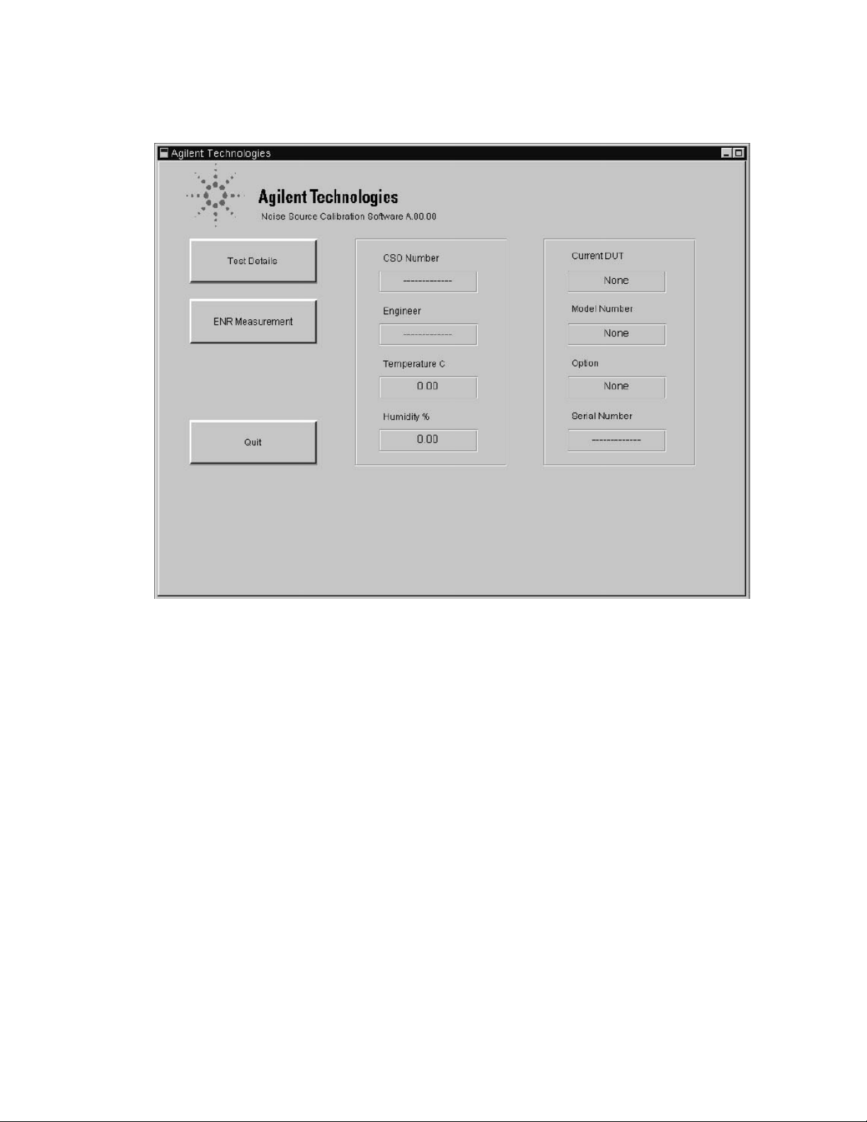
Using the Keysight N2002A Noise Source Demonstration Software
Running the Keysight N2002A Noise Source Demonstration Software
Figure 5-5 The Main Start Up Window Display
The options available to choose from are:
Test Details This allows to enter the details described in “Test Details” on page 65. After
these details are entered they are shown on the Measurement displays. The
details are saved along with the measurement results. Entering these details is
not required for correct operation.
ENR Measurement This selects the ENR display and allows you to configure and perform ENR
Measurements.
Quit Stops the software.
The other information displayed on the Main Start Up Window.
The central display is any information entered in the Test Detail. This includes
the job number and the name of the engineer performing the measurement.
The environmental conditions the measurement is performed under are also
displayed.
The right hand portion of the display is information relating to the noise source
under test (DUT). This includes the noise source manufacturer, the type of
noise source, any options, and the noise source serial number.
Keysight N2002A User’s Guide 61
Page 64
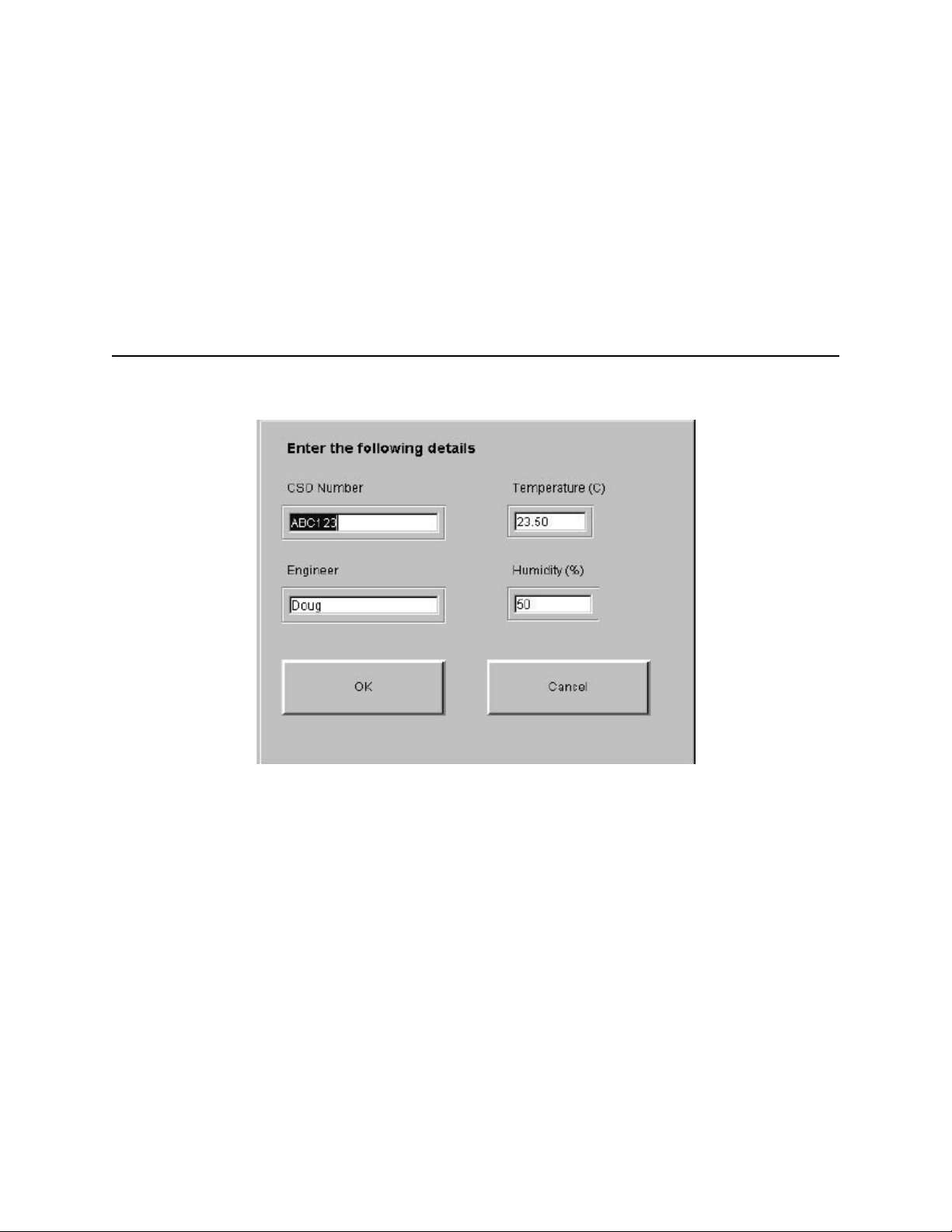
Using the Keysight N2002A Noise Source Demonstration Software
Running the Keysight N2002A Noise Source Demonstration Software
To return to “The ENR Measurement Procedure” on page 58, click the pdf
hot-link.
Test Details
The test details are entered into the fields and are displayed on the
Measurement displays. The Test Details display is shown in Figure 5-6. The
test details are saved with the measurement results.
NOTE Entering these details is not required for correct operation.
Figure 5-6 Test Detail Display
The Test Detail fields are:
CSO Number This allows you to have traceability of the Job Number.
Engineer This allows you to have traceability of the Engineer.
Temperature This allows to enter the ambient temperature where the calibration is made.
The default value is 23.5 ⁰C.
Humidity This allows to enter the ambient humidity where the calibration is made. The
default value is 50.0%.
Clicking the OK button accepts the data entered in the display and returns to
the Measurement display.
Clicking the Cancel button returns to the Measurement display without
accepting the data. No data is shown on the Measurement displays.
62 Keysight N2002A User’s Guide
Page 65
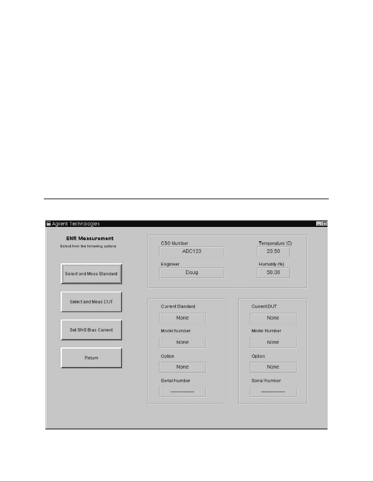
Using the Keysight N2002A Noise Source Demonstration Software
Running the Keysight N2002A Noise Source Demonstration Software
To return to “The ENR Measurement Procedure” on page 58, click the pdf
hot-link.
ENR Measurement
The ENR measurement process is based on making a measurement using a
noise source with known ENR values (The Reference Standard), then making
another measurement on a noise source with unknown ENR values (the Device
Under Test (DUT)). The DUT’s ENR values are now calculated on completion of
the measurement.
The first step to make an ENR measurement is to select ENR Measurement
from the Main Start Up Window. Figure 5-7 shows the ENR Measurement
display.
NOTE Figure 5-4 on page 60 is an example of the warning displayed if a N8975A has
been powered up for less than one hour. It is recommended that no
measurements are made if this warning is shown.
Figure 5-7 The ENR Measurement Display
Keysight N2002A User’s Guide 63
Page 66

Using the Keysight N2002A Noise Source Demonstration Software
Running the Keysight N2002A Noise Source Demonstration Software
The options available to choose from are:
Select and Meas
Standard
Select and Meas
DUT
Set SNS Bias
This selects another display where you can configure and measure a reference
standard.
This selects another display where you can configure and measure a device
under test. The device under test (DUT) is the noise source you are measuring.
This selects a new display where a new SNS bias current can be entered.
Current
Return Returns you to the previous display.
The upper display is the information entered in the Test Details. This includes
the job number and the name of the engineer performing the measurement.
The environmental conditions the measurement is performed under are also
displayed.
The two lower displays shows information relating to the noise source used as
the reference standard and the noise source (DUT) being measured. This
includes the noise source manufacturer, the type of noise source, any options,
and the noise source serial number.
To return to “The ENR Measurement Procedure” on page 58, click the pdf
hot-link.
Selecting and Measuring the Reference Standard
Clicking the Select and Meas Standard button on the ENR Measurement
display, produces a display similar to Figure 5-8 on page 65.
This process step must be followed before a DUT can be measured.
1. A reference standard must be selected and a measurement performed on
it.
2. The ENR measurement uncertainty data must be entered for the reference
standard.
64 Keysight N2002A User’s Guide
Page 67
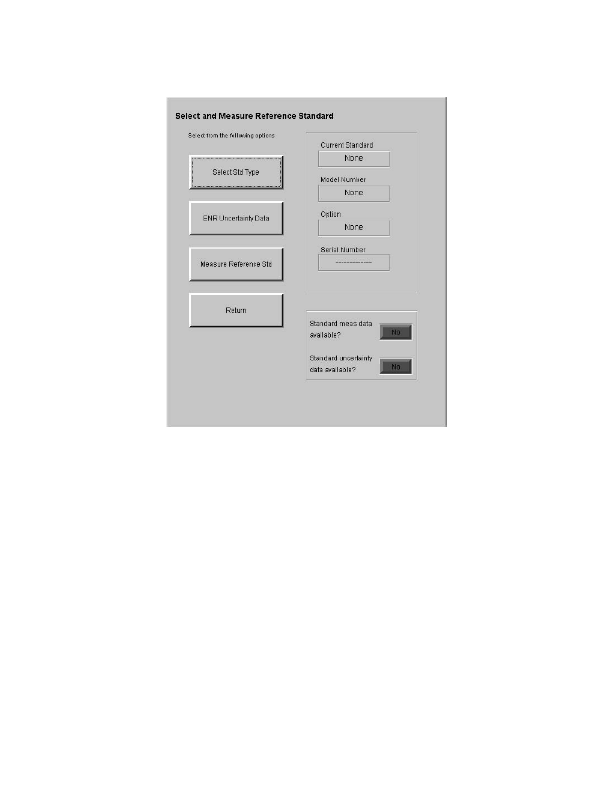
Using the Keysight N2002A Noise Source Demonstration Software
Running the Keysight N2002A Noise Source Demonstration Software
Figure 5-8 Select and Measure Reference Standard
The options available to choose from are:
Select Std Type This selects another display allowing you to enter the reference standard’s
details.
ENR Uncertainty
Data
Measure
Reference
This allows access to other displays allowing you to enter and manipulate the
reference standard’s ENR measurement uncertainty data.
This initiates measurement of the reference standard. A reference standard
must be selected before a measurement can be made.
Standard
Return Returns you to the previous display.
The upper display shows information relating to the reference standard. This
includes the noise source manufacturer, the type of noise source, any options,
and the noise source serial number.
The lower display shows the current status of data relating to the reference
standard.
Keysight N2002A User’s Guide 65
Page 68
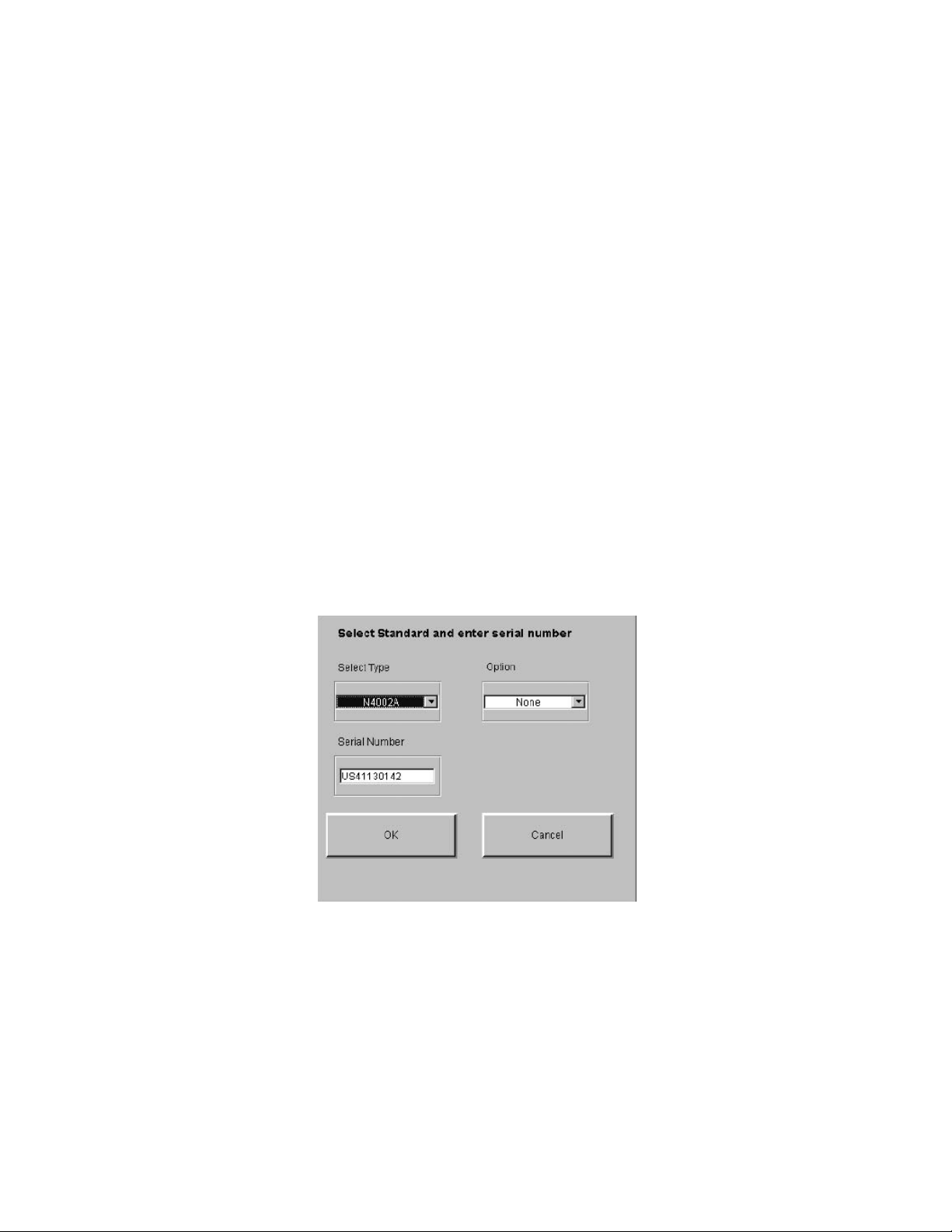
Using the Keysight N2002A Noise Source Demonstration Software
Running the Keysight N2002A Noise Source Demonstration Software
Standard Meas
Data Available?
Standard
Uncertainty Data
Available?
Selecting the Reference Standard
A DUT measurement is not possible until the reference standard’s uncertainty
date has been entered and the measurement has been made on the reference
standard. This indicator is red until the measurements have been made. When
these measurements are complete the indicator is green. The indicator returns
to red when a new reference standard is selected.
A DUT measurement is not possible until the ENR measurement uncertainty
values for the reference standard are available. This indicator is red until the
measurement uncertainty values are available. When these measurements
uncertainty values are available the indicator is green. The indicator returns to
red when a new reference standard is selected.
To return to “The ENR Measurement Procedure” on page 58, click the pdf
hot-link.
A reference standard must be selected before proceed ing. See “Reference
Standard Noise Source Selection” on page 28 for more information on
selecting the reference standard.
Clicking the Select Std Type from the Select and Measure Reference
Standard window shows a display similar to Figure 5-9.
Figure 5-9 Select Reference Standard Type and Serial Number
The options available to choose from are:
Select Type This allows you to select the type of reference standard. The options to choose
from are 346A, 346B, 346C, N4000A, N4001A, N4002A, and Other. The Other
option covers all other manufacturer’s noise sources or Keysight noise sources
operating at frequencies other than the standard cardinal values. See
“Selecting Other” on page 79 for a further explanation.
Option A list of Options available are shown. The available options depend on the type
of reference standard selected.
66 Keysight N2002A User’s Guide
Page 69
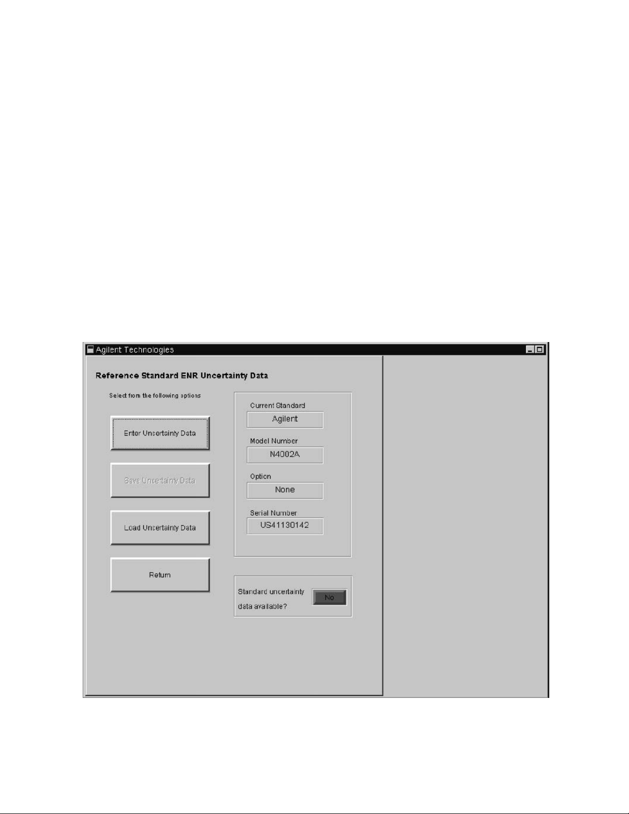
Using the Keysight N2002A Noise Source Demonstration Software
Running the Keysight N2002A Noise Source Demonstration Software
Serial Number The Serial Number of the reference standard is entered in this field.
Clicking the OK button accepts the entered data and returns you to the
previous display.
Clicking the Cancel button ignores any changes and returns you to the
previous display.
To return to “The ENR Measurement Procedure” on page 58, click the pdf
hot-link.
Entering Reference Standard Uncertainty Data
A DUT measurement is not possible until the reference standard’s ENR
measurement uncertainty data is available. This indicator is red until the
measurement uncertainty data is available. When the measurement
uncertainty data is available the indicator is green. The indicator returns to red
when a new reference standard is selected. Figure 5-10 shows a typical display
before uncertainty date has been entered.
Figure 5-10 Reference Standard ENR Uncertainty Data
The options available to choose from are:
Keysight N2002A User’s Guide 67
Page 70

Using the Keysight N2002A Noise Source Demonstration Software
Running the Keysight N2002A Noise Source Demonstration Software
Enter Uncertainty
Values
Selecting this produces a display of the number of frequency points in the
reference standard selected. There are three possible displays:
1. Covering the Keysight 346A, 346B, N4000A, and N4001A noise sources
(10.0 MHz to 18.0 GHz). This display type is shown in Figure 5-11.
2. Covering the Keysight 346C and N4002A noise sources (10.0 MHz to 26.5
GHz).
3. Covering Other noise source types and frequency points. See “Selecting
Other” on page 79 for an explanation of this.
Save Uncertainty
Data
Select this to save the reference standard’s measurement uncertainty data to a
file. This key is unavailable until Uncertainty data has been entered. The file is
saved to
C:\N2002A\Standard\Uncertainty Values\.
The measurement uncertainty data is saved with the model number and serial
number of the reference standard.
Load Uncertainty
Data
NOTE Ensure the reference standard’s model number and serial number match the
Select this if the reference standard’s uncertainty data is available on file
(C:\N2002A\Standard\Uncertainty Values\).
values in the saved data.
Return Returns you to the Select and Measure Standard display.
The upper display shows the current reference standard’s data. The data is the
manufacturer, noise source model, option, and serial number.
The lower display indicates if the uncertainty data is valid for the selected
reference standard. The indicator is green when the data is valid.
A DUT measurement is not possible until the ENR measurement uncertainty
values for the reference standard are available. The indicator is red until
measurement uncertainty values are available. When ENR measurement
uncertainty data is available for the reference standard, and the indicator on
the Standard uncertainty data available? display is green. The indicator returns
to red when a new reference standard is selected.
NOTE Measurement uncertainty data need not be entered before performing a
measurement on the reference standard. However, measurement uncertainty
data for the reference standard has to be available before a DUT
measurement can be made.
To return to “The ENR Measurement Procedure” on page 58, click the pdf
hot-link.
68 Keysight N2002A User’s Guide
Page 71
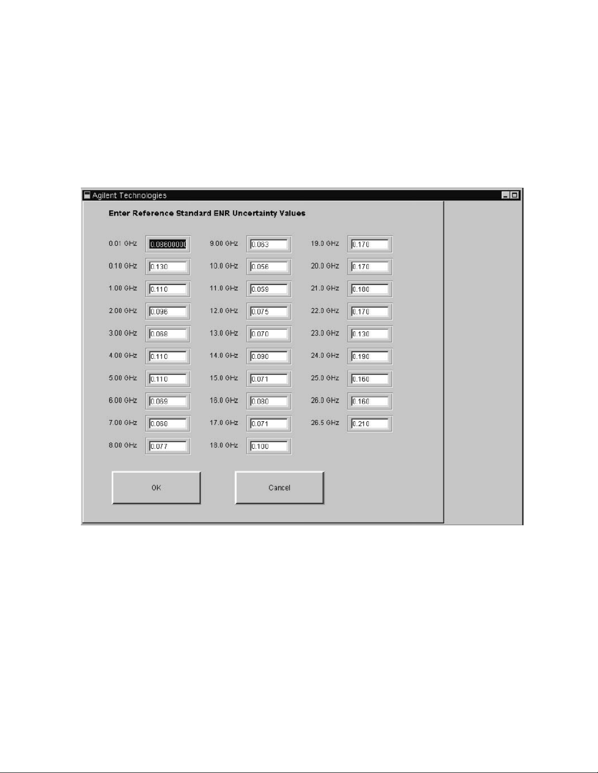
Using the Keysight N2002A Noise Source Demonstration Software
Running the Keysight N2002A Noise Source Demonstration Software
Selecting Reference Standard Measurement Uncertainty Data
Clicking Enter Uncertainty Values on the Reference Stand ard ENR
Uncertainty Data displays a table of fields similar to Figure 5-11. Data must be
entered in the fields or measurements cannot be made. After the uncertainty
data has been entered, click OK. This returns you to the previous display and
the Standard uncertainty data available? indicator is now green.
Figure 5-11 Typical Reference Standard ENR Uncertainty Data
To return to “The ENR Measurement Procedure” on page 58, click the pdf
hot-link.
Performing Reference Standard Measurement
When a reference standard has been selected with its ENR table data and
Uncertainty Data entered, a measurement can be made. The measurement
process is started by clicking the Measure Reference Standard button. This
button is on the Select and Measure Standard display. The measurement
results are not displayed during this process. However, a Measuring frequency
point counter, shown in Figure 5-12 on page 70, is displayed indicating a
Keysight N2002A User’s Guide 69
Page 72
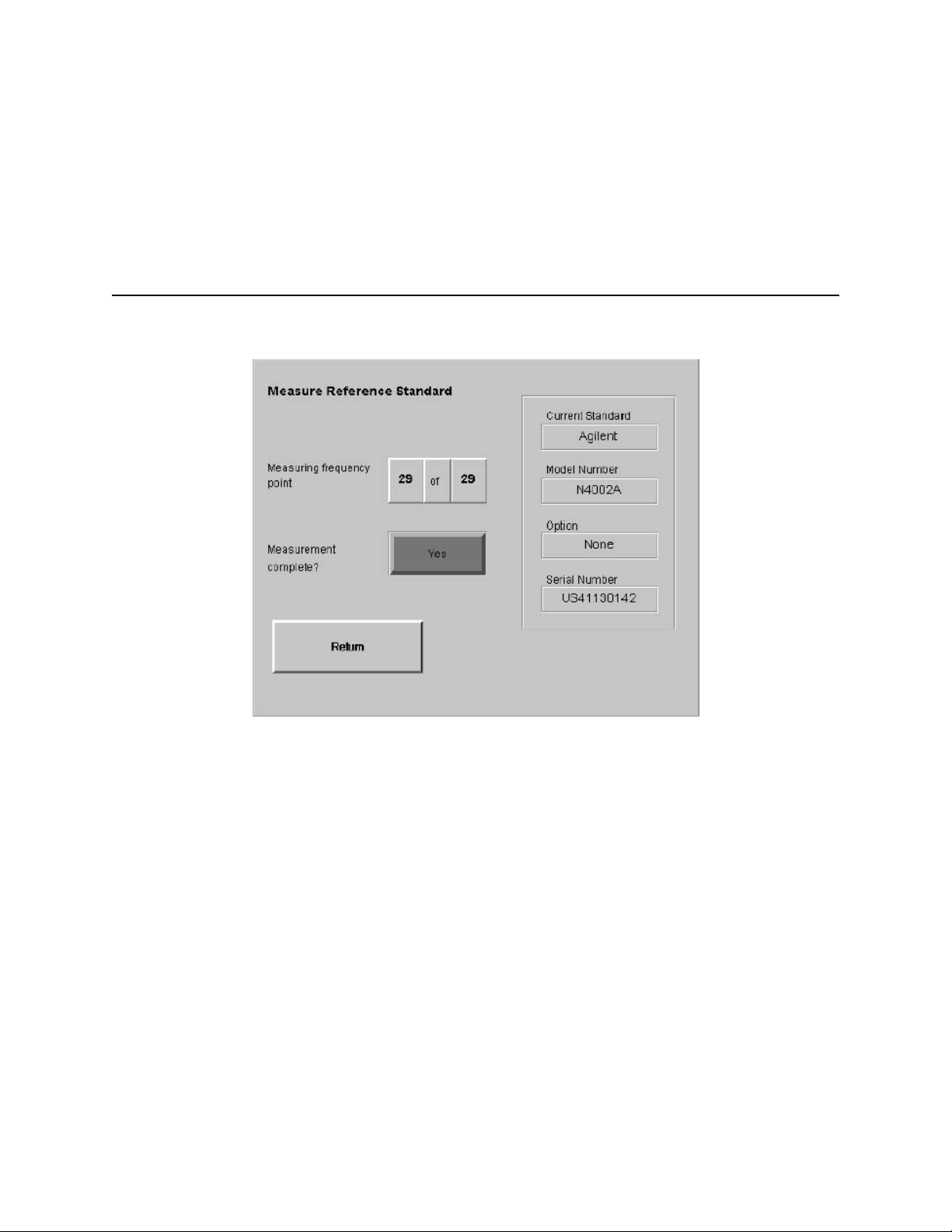
Using the Keysight N2002A Noise Source Demonstration Software
Running the Keysight N2002A Noise Source Demonstration Software
measurement is being performed. When testing is complete the Measurement
Complete? indicator changes from red to green. Click Return to return to the
Select and Measure Reference Standard display.
NOTE A Reference Standard’s measurement need not be repeated before every DUT
measurement. However, Keysight Technologies recommend for best result a
Reference Standard’s has been performed regularly.
Figure 5-12 Measure Reference Standard Display
To return to “The ENR Measurement Procedure” on page 58, click the pdf
hot-link.
70 Keysight N2002A User’s Guide
Page 73
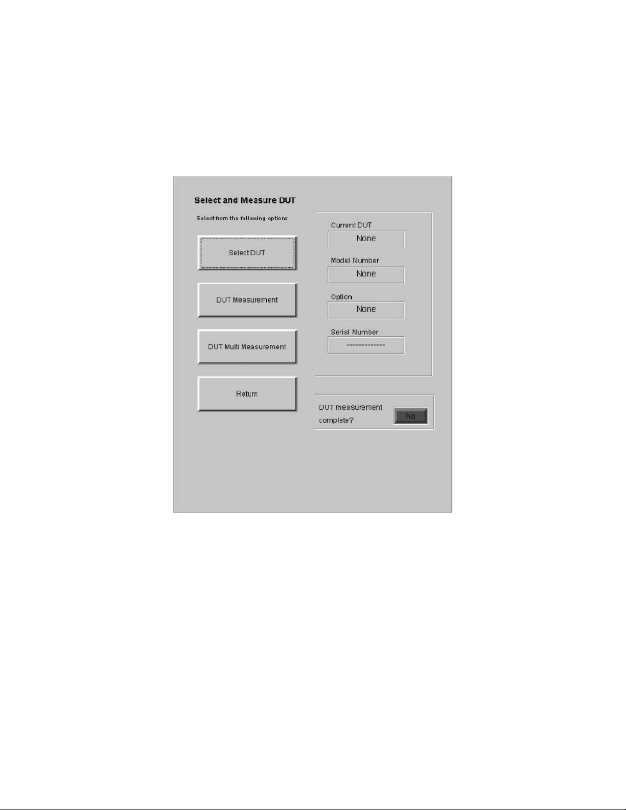
Using the Keysight N2002A Noise Source Demonstration Software
Running the Keysight N2002A Noise Source Demonstration Software
Selecting the DUT to be Measured
When the reference standard measurement is complete, the DUT can be
measured. Clicking Select and Meas DUT on the ENR Measurement display
shows a similar display to Figure 5-13 on page 71.
Figure 5-13 Select and Measure DUT
The options available to choose from are:
Select DUT This selects another display where you can enter information about the device
under test (DUT).
DUT Measurement Starts a single DUT measurement. The DUT is measured only on one occasion,
at all the designated frequency points.
DUT Multi
Measurement
Keysight N2002A User’s Guide 71
Starts a multiple DUT measurement. The DUT can be repeatedly measured, up
to a maximum of twelve repeats, at all the designated frequency points.
Page 74
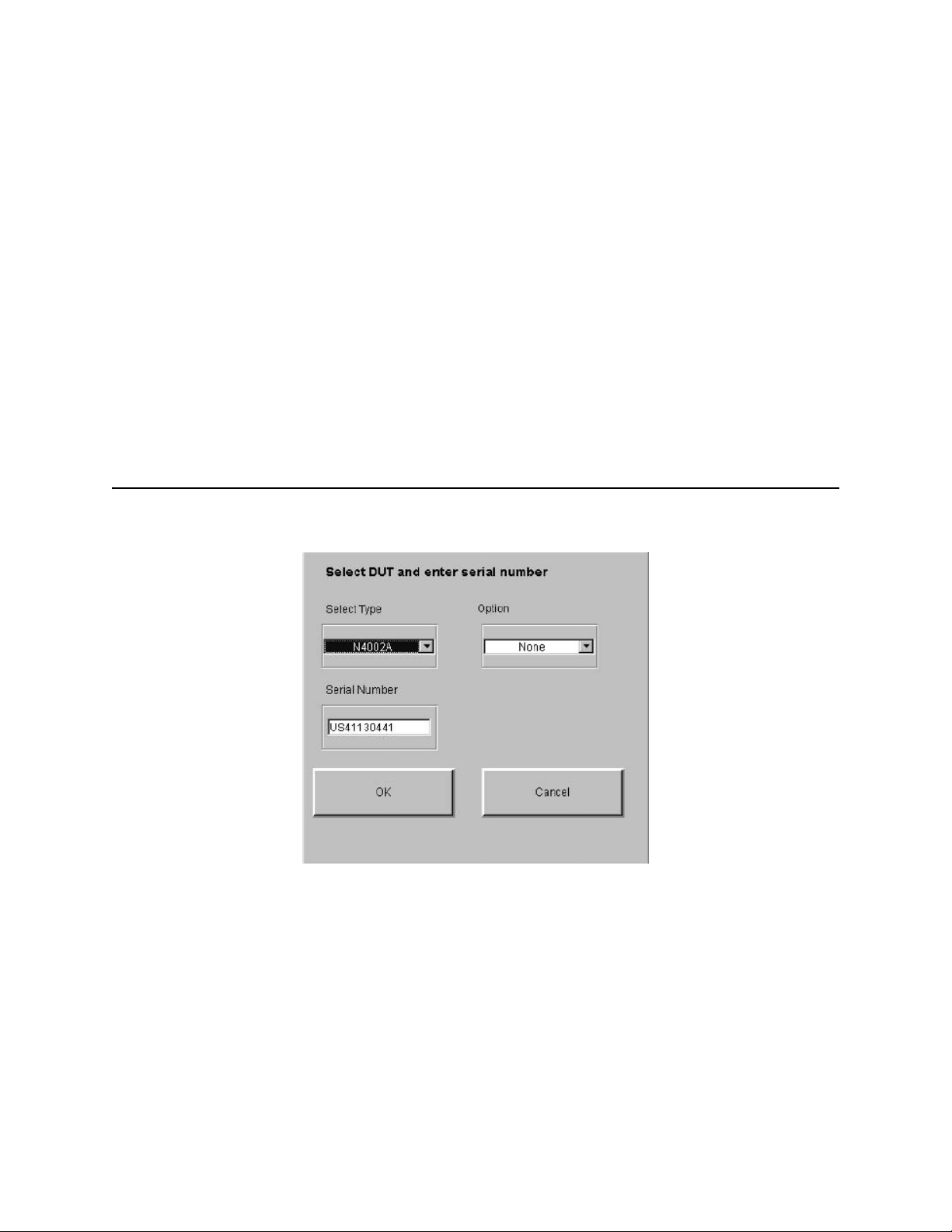
Using the Keysight N2002A Noise Source Demonstration Software
Running the Keysight N2002A Noise Source Demonstration Software
Return Returns you to the previous display.
The upper display is any information entered in the Test Details. This includes
the job number and the name of the engineer performing the measurement.
The environmental conditions the measurement is performed under are also
displayed.
To return to ““The ENR Measurement Procedure” on page 58, click the pdf
hot-link.
Selecting the DUT
NOTE Any noise source can be selected as a reference standard. However, a
warning is displayed if you measure a DUT with a different frequency range.
For example, if you use a 346B as a reference standard and attempt to
measure a 346C a caution is displayed stating that the measurements are
limited to 18.0 GHz.
Figure 5-14 Select DUT Type and Serial Number
The options available to choose from are similar to the “Selecting and
Measuring the Reference Standard” on page 64.
Select Type This allows you to choose the DUT type being measured. The choices are 346A,
346B, 346C, N4000A, N4001A, N4002A, and Other.
Other allows you to test other manufacturer’s noise sources or Keysight noise
sources using at non-standard frequency values. See “Selecting Other” on
page 79 for an explanation of this.
Option A list of available options are shown. The options available depend on the type
of DUT selected.
72 Keysight N2002A User’s Guide
Page 75

Using the Keysight N2002A Noise Source Demonstration Software
Running the Keysight N2002A Noise Source Demonstration Software
Serial Number The Serial Number of the DUT is entered in this field.
Clicking the OK button accepts the data that has been entered and returns you
to the Select and Measure DUT display. This data is displayed in the window.
Clicking the Cancel button ignores the changes and returns you to the Select
and Measure DUT display.
To return to “The ENR Measurement Procedure” on page 58, click the pdf
hot-link.
Measuring a DUT
Selecting the DUT Measurement button starts a single DUT measurement and
displays the results as they are completed. A measurement is made on the DUT
at the first measurement frequency point. The DUT’s ENR and ENR
measurement uncertainty results are calculated for the DUT at this frequency
point. The results are displayed with the frequency point the measurement was
made at. The process is repeated for all the measurement frequency points.
The display is updated with results, one frequency point at a time. When the
final result is obtained a display similar to Figure 5-15 is presented.
If a DUT measurement is not possible a warning message is displayed. The
warning message indicates the reason the DUT measurement is not possible.
Keysight N2002A User’s Guide 73
Page 76
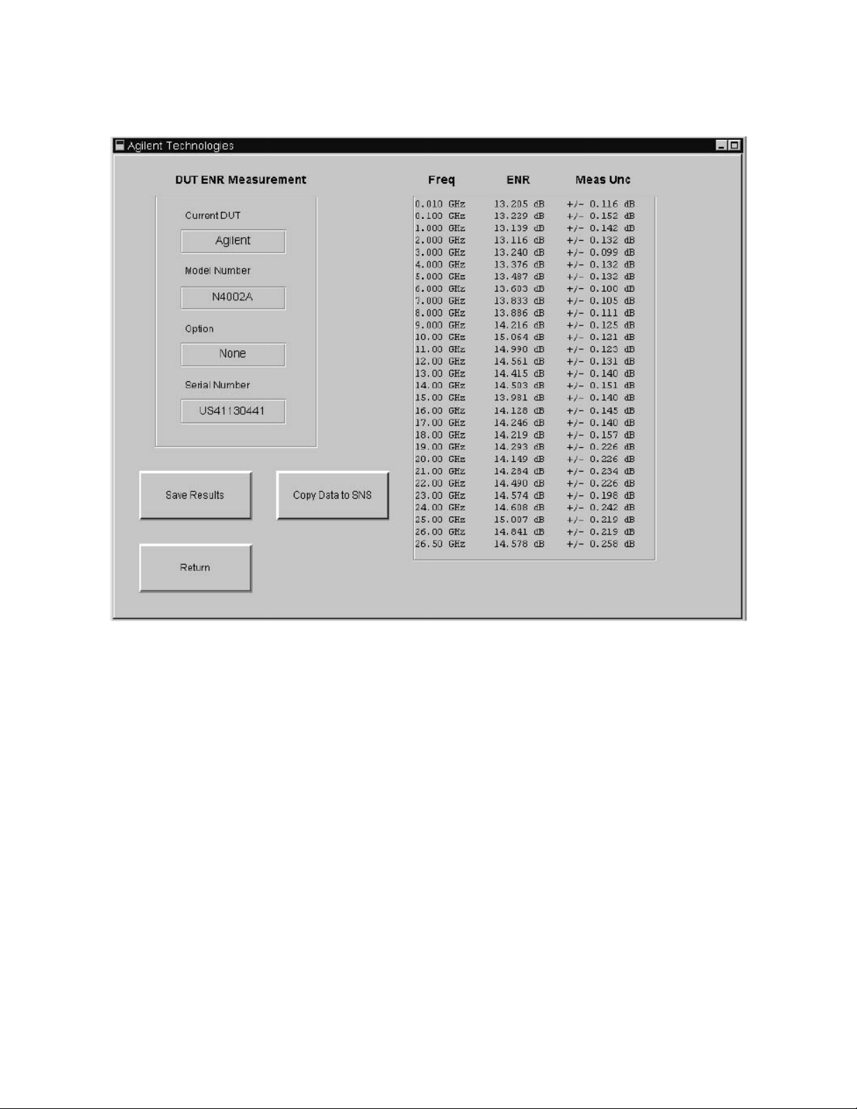
Using the Keysight N2002A Noise Source Demonstration Software
Running the Keysight N2002A Noise Source Demonstration Software
Figure 5-15 An Example of Result Data
The options available to choose from are:
Save Results This option is not available until the DUT measurement is completed. The ENR
values and measurement uncertainty values are saved with the measurement
frequency points. Also, saved are the DUT’s identification details, the reference
standard’s details, the job details, the environmental conditions the test was
performed in, the date of the test, and the software revision. An example of a
test result file is shown in Figure 5-16.
Test results are saved as a text files to:
C:\N2002A\DUT Test Results\ENR\
The results are saved under an automatically generated filename. The filename
is made up from the DUT model number, the DUT serial number, and the date
the test results were made, for example,
N4002A_US4110000_yyyymmdd_hh_mm_ss.txt.
74 Keysight N2002A User’s Guide
Page 77
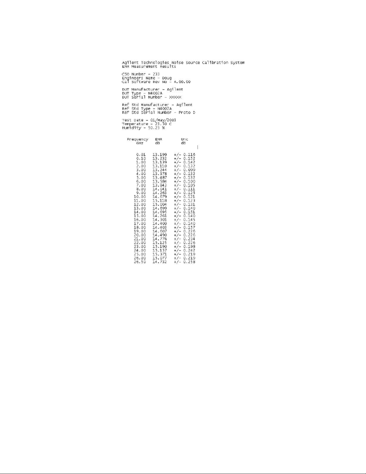
Using the Keysight N2002A Noise Source Demonstration Software
Running the Keysight N2002A Noise Source Demonstration Software
Figure 5-16 Example of a Single ENR Measurement Result Data
Copy Data to SNS This option is only available if the DUT is an Keysight N400xA series noise
source and the DUT measurement is complete. The process is explained in
“Copying Data to SNS” on page 75.
Return Returns you to the ENR Measurement display.
To return to “The ENR Measurement Procedure” on page 58, click the pdf
hot-link.
Copying Data to SNS
Figure 5-17 shows a warning message displayed after clicking Copy Data to
SNS, click OK if you want to continue.
Keysight N2002A User’s Guide 75
Page 78
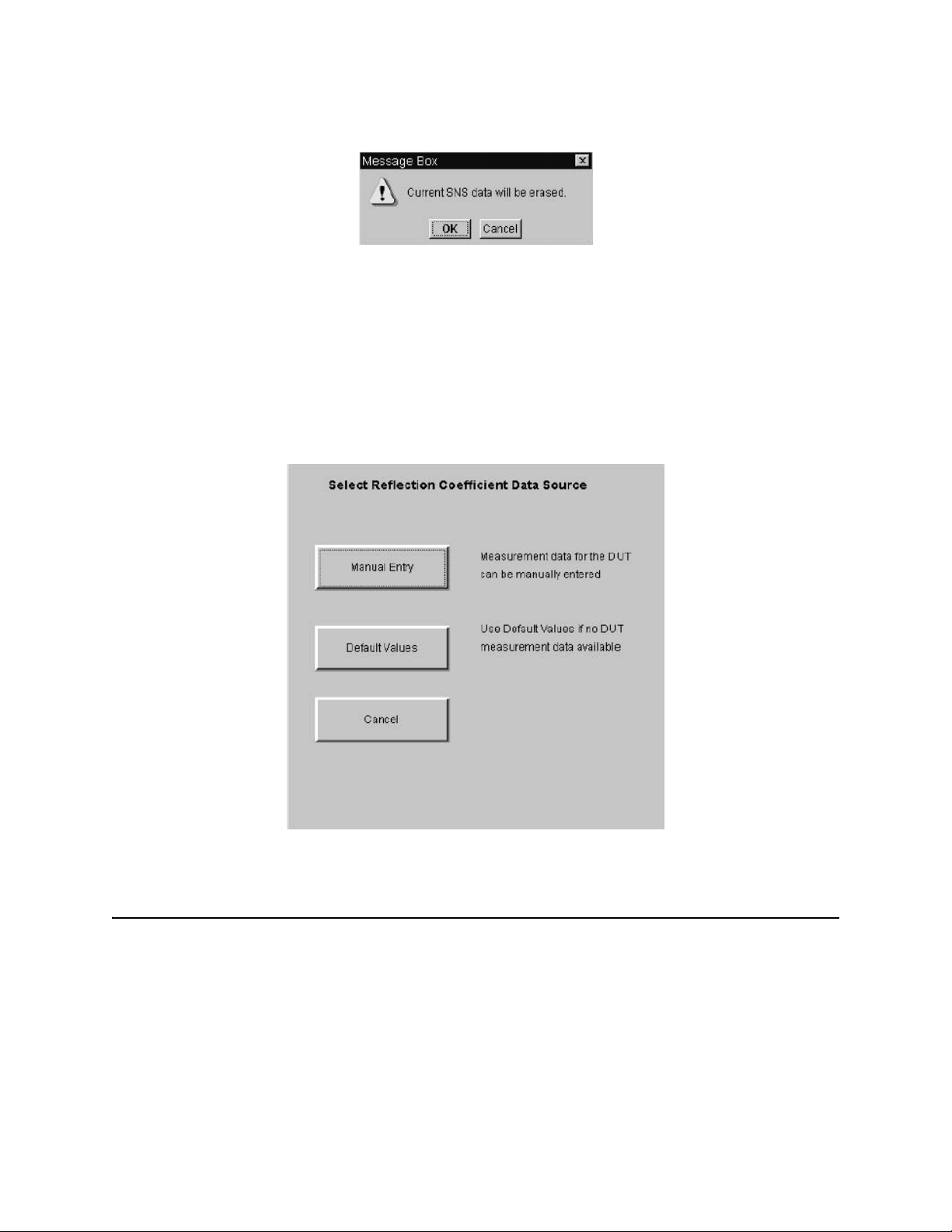
Using the Keysight N2002A Noise Source Demonstration Software
Running the Keysight N2002A Noise Source Demonstration Software
Figure 5-17 Warning Message for SNS Erased Data
The Keysight N400xA SNS’s have ENR and reflection coefficient data values
stored in their EEPROM. New data can be written to the SNS when an ENR
measurement has been completed. The data written to the SNS consists of the
ENR result, the ENR measurement uncertainty result and the reflection
coefficient measurement result data.
There are two options for the reflection coefficient measurement result data.
The Copy Data to SNS function shows the Figure 5-18 display.
Figure 5-18 Saving SNS Result Data
NOTE On an SNS, Reflection Coefficient data must be entered.
The options available to choose from are:
Manual Entry The results for reflection coefficient magnitude and phase must be entered
manually. Figure 5-19 shows a typical window allowing you to enter the
Reflection Magnitude Values for the DUT Off condition. You are presented with
three other windows, namely Reflection Magnitude Values for the DUT On,
Reflection Phase Values for the DUT Off, and Reflection Phase Values for the
DUT On.
76 Keysight N2002A User’s Guide
Page 79
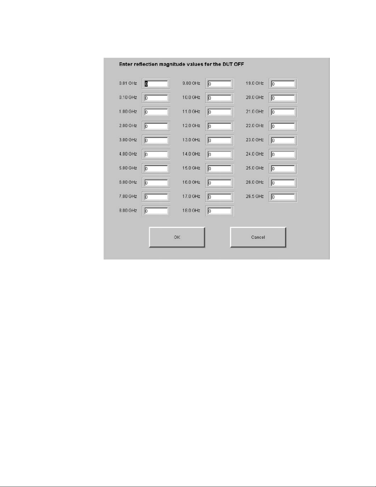
Using the Keysight N2002A Noise Source Demonstration Software
Running the Keysight N2002A Noise Source Demonstration Software
Figure 5-19 Manual VSWR Entry Window
Default Values If no reflection coefficient measurement data is available for the DUT, default
values are used. This option uses the ENR measurement results but all
reflection coefficient measurement data is set to zero.
Cancel Returns you to the DUT ENR Measurement display.
To return to “The ENR Measurement Procedure” on page 58, click the pdf
hot-link
Making Multi Measurement on a DUT
DUT Multi Measurement is similar to DUT Measurement, but the measurement
can be repeated up to a maximum of twelve times. This allows you, for
example, to look for any repeatability effects. Clicking the DUT Multi
Measurement button on the Select and Measure DUT window starts the
measurement process. When the final result is obtained a display similar to
Figure 5-20 is presented.
The number of required measurement repeats are entered at the start of the
measurement, up to a maximum of twelve. A measurement is made on the DUT
at the first measurement frequency point. The DUT’s ENR results are calculated
for the DUT at this frequency point. The ENR measurement result is the only
Keysight N2002A User’s Guide 77
Page 80
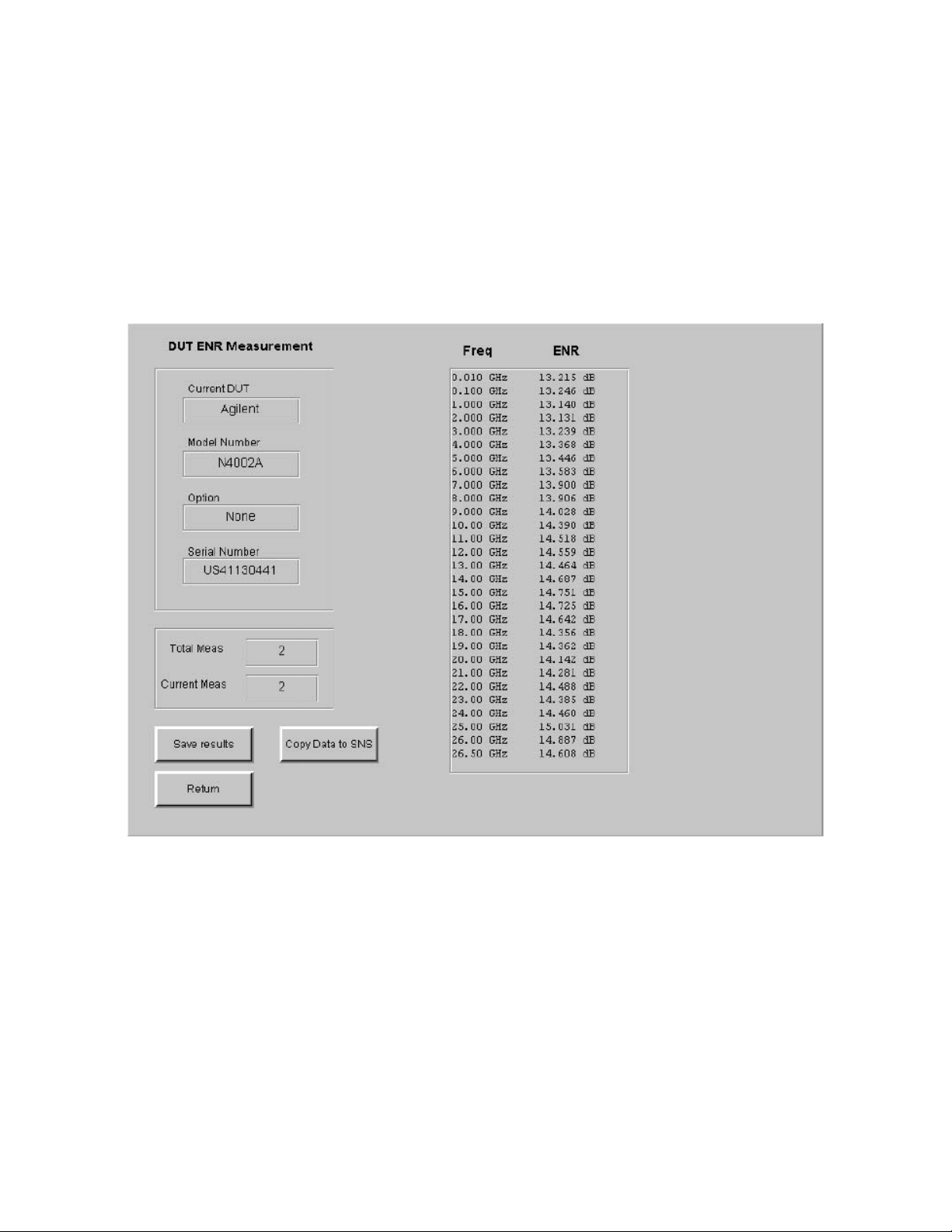
Using the Keysight N2002A Noise Source Demonstration Software
Running the Keysight N2002A Noise Source Demonstration Software
value calculated and the result is displayed with the frequency point the
measurement was made at. When the measurement is completed, you are
prompted to continue with the next measurement. The previous measurement
results are cleared from the display and DUT measurement starts at the first
measurement frequency point.
The process is repeated for all measurement frequency points. The display is
updated with the DUT’s ENR results for one frequency point at a time.
Figure 5-20 ENR Multi Measurement Result Data
The options available to choose from are:
Save Results Measurement results can be saved as a comma separated values file (.csv)
which can then be imported into Microsoft Excel for analysis.
Figure 5-21 on page 79 is an example of the measurement results data
displayed on a spreadsheet.
78 Keysight N2002A User’s Guide
Page 81
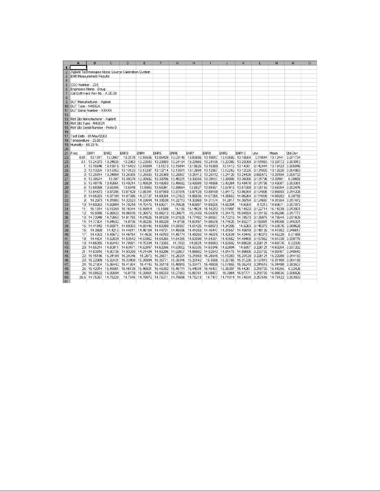
Using the Keysight N2002A Noise Source Demonstration Software
Running the Keysight N2002A Noise Source Demonstration Software
Figure 5-21 Example of ENR Multi Measurement Result Data as CSVs
Copy data to SNS Data can be copied to an SNS DUT, but it must be entered manually.
Return Returns you to the ENR Measurement display.
To return to “The ENR Measurement Procedure” on page 58, click the pdf
hot-link.
Selecting Other
The Other option covers all other manufacturer’s noise sources or Keysight
noise sources operating at frequencies other than the standard cardinal values.
The number of data points is controlled by the number of Frequency/ENR pairs
in the NFA. Before performing a measurement using reference standard of type
Other, an ENR table containing the measurement frequencies and ENR values
to be used must be created in the NFA.
The display contains one field for each measurement frequency. The ENR
measurement uncertainty for the reference standard must be entered manually
for each frequency point. The interpolated values are also calculated manually.
Keysight N2002A User’s Guide 79
Page 82
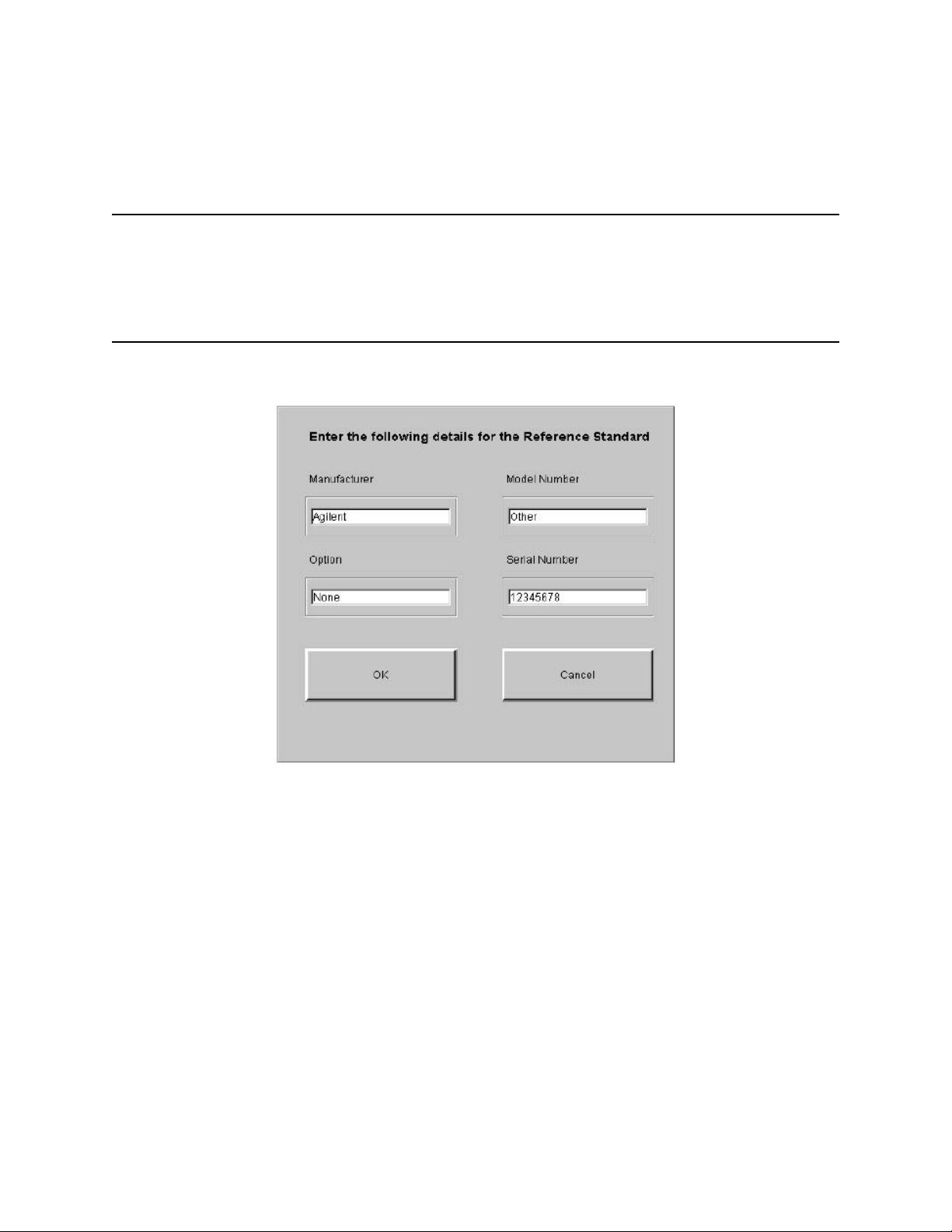
Using the Keysight N2002A Noise Source Demonstration Software
Running the Keysight N2002A Noise Source Demonstration Software
Selecting Other as the DUT type produces the display similar to Figure 5-22.
NOTE The NFA can only store a maximum of 81 Frequency/ENR pairs.
NOTE Any DUT can be measured using any reference standard. However,
measurement is limited to 18.0 GHz if the reference standard, or DUT, is an
Keysight 346A, 346B, N4000A, or N4001A.
Figure 5-22 Typical Other Display
The data is entered manually in these fields. The data required is:
Manufacturer The DUT manufacturer.
Model Number The DUT model number.
Option Any DUT options.
Serial Number The DUT serial number.
Clicking the OK button accepts the data that has been entered. Clicking the
Cancel button ignores the changes and returns you to the ENR Measurement
display.
Figure 5-23 is a typical display of the Reference Standard’s ENR Uncertainty
Values.
80 Keysight N2002A User’s Guide
Page 83
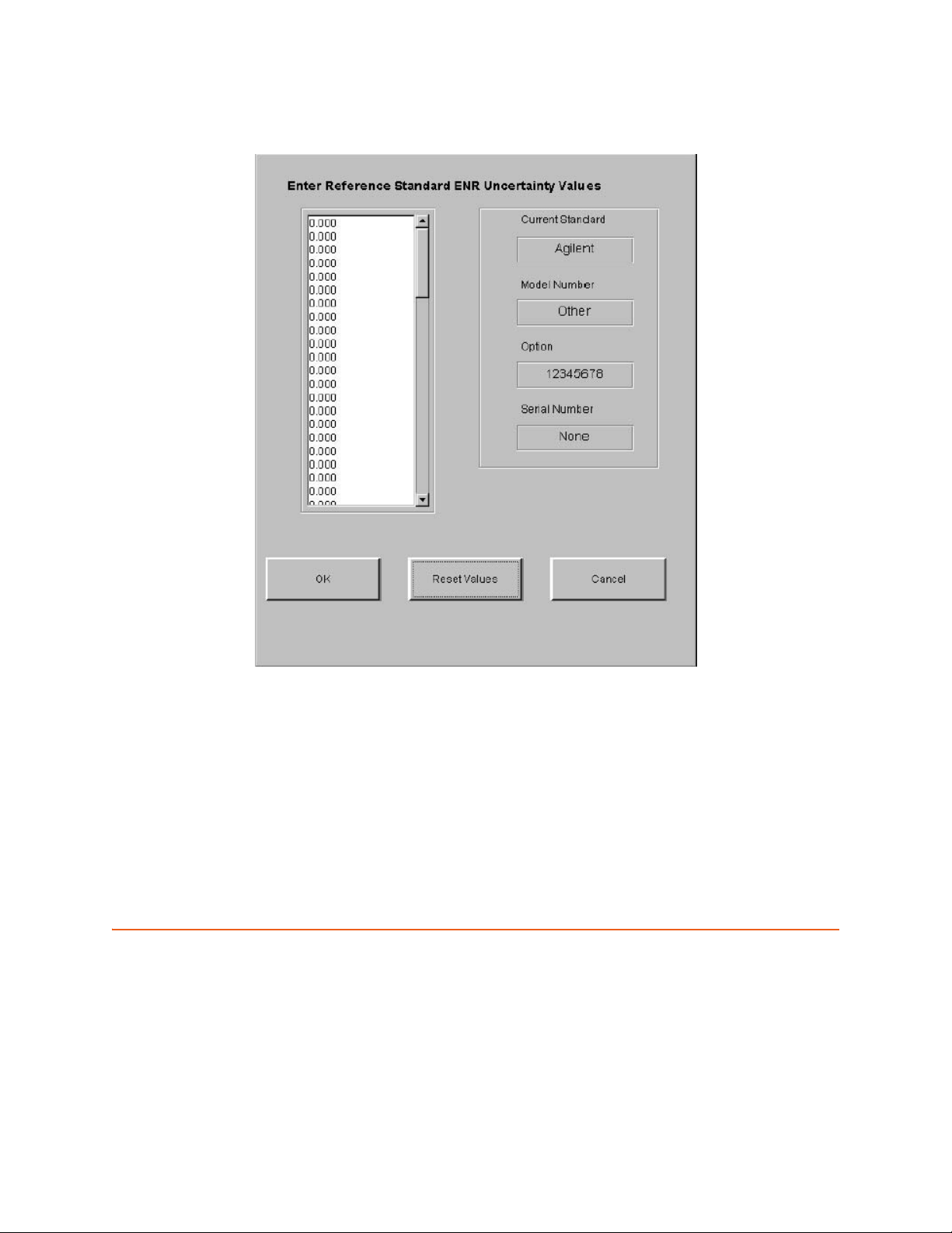
Using the Keysight N2002A Noise Source Demonstration Software
Running the Keysight N2002A Noise Source Demonstration Software
Figure 5-23 Enter Uncertainly Values for Other
Setting SNS Bias Current
When repairing an SNS, certain replacement parts are suppled with a value of
bias current. This information should be programmed to make the SNS work
correctly.
CAUTION Performing a SNS Bias Current setting wrongly can make your SNS
inoperatable. Keysight Technologies recommend this is only performed by
trained operators. If you attempt to do this a warning is displayed similar to
Figure 5-24 on page 82.
Keysight N2002A User’s Guide 81
Page 84
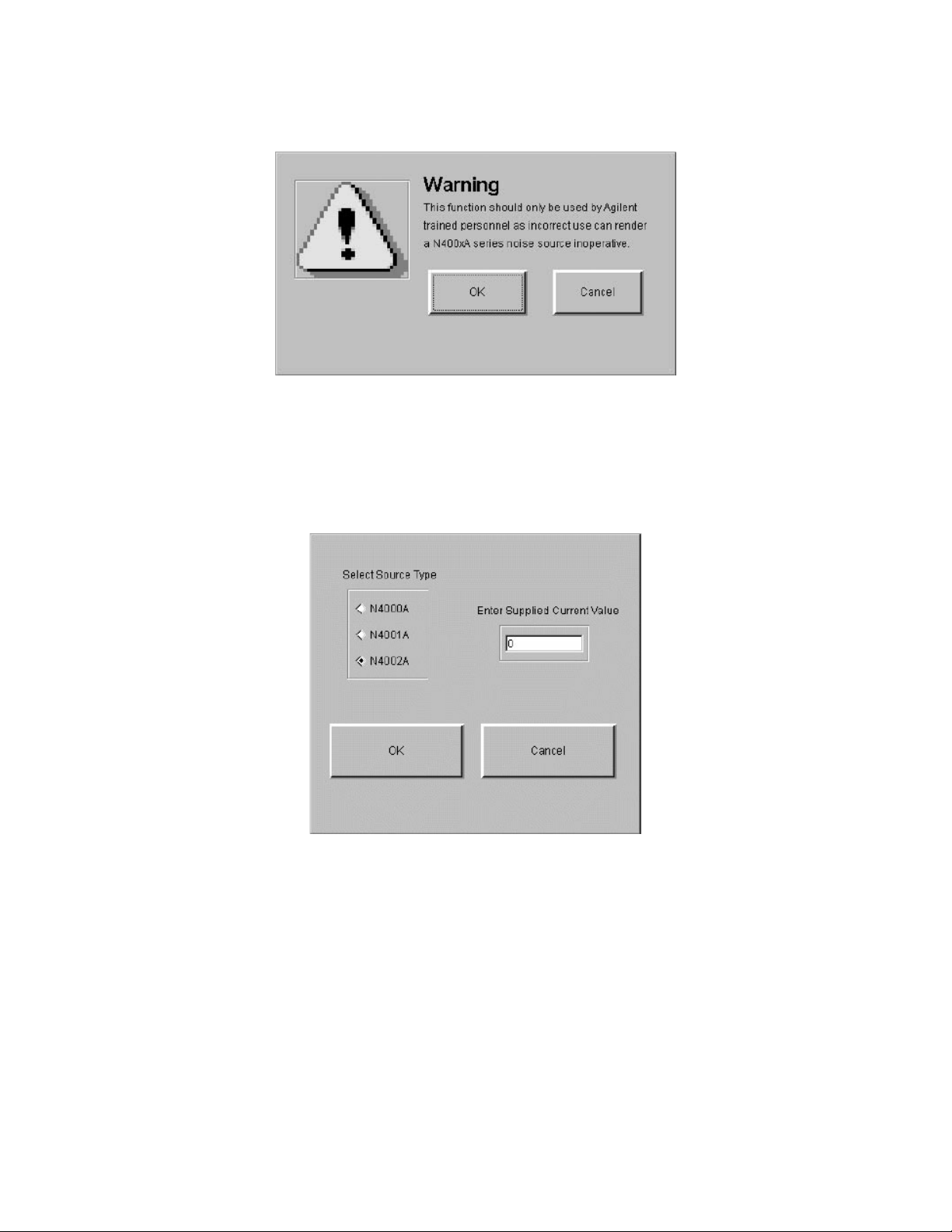
Using the Keysight N2002A Noise Source Demonstration Software
Running the Keysight N2002A Noise Source Demonstration Software
Figure 5-24 SNS Bias Current Warning
Selecting OK displays a window similar to Figure 5-25 on page 82.
Select the SNS type you want to set the bias current on and enter the value of
bias current supplied with the new assembly in the Enter Supplied Current
Value field.
Figure 5-25 SNS Bias Current Source Selection
After the SNS Bias Current setting is complete, you need to measure the SNS
to confirm the ENR values are within the published specifications.
82 Keysight N2002A User’s Guide
Page 85

Keysight Technologies
Noise Source Test Set
N2002A
A: Test Records for the 346A
This appendix provides test records for you to photocopy and use when
performing each calibration and verification test. As the reflection coefficient
and phase test use two VNAs, the test records are provided with a convenient
break point at 3.0 GHz.
83
Page 86

Test Records for the 346A
Reflection Coefficient Magnitude and Phase Test Record
Reflection Coefficient Magnitude and Phase Test Record
Frequency
Range (MHz)
10.0 to 30.0 ≤0.13
30.0 to
3000.0
3000.0 to
5000.0
5000.0 to
18000.0
Freq. (MHz) Source OFF Reflection
Coefficient
Magnitude Phase Magnitude Phase
10.0 ≤0.13
100.0 ≤0.07
1000.0 ≤0.07
2000.0 ≤0.07
3000.0 ≤0.07
4000.0 ≤0.07
Source ON Reflection
Coefficient
Spec. Pass/
≤0.07
≤0.07
≤0.11
Fail
5000.0 ≤0.07
6000.0 ≤0.11
7000.0 ≤0.11
8000.0 ≤0.11
9000.0 ≤0.11
10000.0 ≤0.11
11000.0 ≤0.11
12000.0 ≤0.11
13000.0 ≤0.11
14000.0 ≤0.11
15000.0 ≤0.11
16000.0 ≤0.11
17000.0 ≤0.11
18000.0 ≤0.11
84 Appendix A
Page 87

Test Records for the 346A
Excess Noise Ratio (ENR) Test Record
Excess Noise Ratio (ENR) Test Record
Frequency (MHz) Standard ENR1 (dB) Stand ard Y1 (Lin) DUT Y2 (Lin) DUT ENR2 (dB)
10.0
100.0
1000.0
2000.0
3000.0
4000.0
5000.0
6000.0
7000.0
8000.0
9000.0
10000.0
11000.0
12000.0
13000.0
14000.0
15000.0
16000.0
17000.0
18000.0
Appendix A 85
Page 88

Test Records for the 346A
Uncertainty Test Record
Uncertainty Test Record
Frequency (MHz) (UcENR1)
Standard ENR
10.0 0.0785
100.0 0.0785
1000.0 0.0905
2000.0 0.0905
3000.0 0.0726
4000.0 0.0726
5000.0 0.0726
6000.0 0.0726
7000.0 0.0800
8000.0 0.0800
9000.0 0.1076
10000.0 0.1076
11000.0 0.1076
Uncertainty (dB)
1
(UcSys)
System Uncertainty (dB)
(UcENR2)
DUT ENR
Uncertainty (dB)
2
12000.0 0.1076
13000.0 0.1211
14000.0 0.1211
15000.0 0.1211
16000.0 0.1211
17000.0 0.1211
18000.0 0.1211
86 Appendix A
Page 89

Keysight Technologies
Noise Source Test Set
N2002A
B: Test Records for the 346B
This appendix provides test records for you to photocopy and use when
performing each calibration and verification test. As the reflection coefficient
and phase test use two VNAs, the test records are provided with a convenient
break point at 3.0 GHz.
87
Page 90

Test Records for the 346B
Reflection Coefficient Magnitude and Phase Test Record
Reflection Coefficient Magnitude and Phase Test Record
Frequency
Range (MHz)
10.0 to 30.0 ≤0.13
30.0 to
3000.0
3000.0 to
5000.0
5000.0 to
18000.0
Freq. (MHz) Source OFF Reflection
Coefficient
Magnitude Phase Magnitude Phase
10.0 ≤0.13
100.0 ≤0.07
1000.0 ≤0.07
2000.0 ≤0.07
3000.0 ≤0.07
4000.0 ≤0.07
Source ON Reflection
Coefficient
Spec. Pass/
≤0.07
≤0.07
≤0.11
Fail
5000.0 ≤0.07
6000.0 ≤0.11
7000.0 ≤0.11
8000.0 ≤0.11
9000.0 ≤0.11
10000.0 ≤0.11
11000.0 ≤0.11
12000.0 ≤0.11
13000.0 ≤0.11
14000.0 ≤0.11
15000.0 ≤0.11
16000.0 ≤0.11
17000.0 ≤0.11
18000.0 ≤0.11
88 Appendix B
Page 91

Test Records for the 346B
Excess Noise Ratio (ENR) Test Record
Excess Noise Ratio (ENR) Test Record
Frequency (MHz) Standard ENR1 (dB) Stand ard Y1 (Lin) DUT Y2 (Lin) DUT ENR2 (dB)
10.0
100.0
1000.0
2000.0
3000.0
4000.0
5000.0
6000.0
7000.0
8000.0
9000.0
10000.0
11000.0
12000.0
13000.0
14000.0
15000.0
16000.0
17000.0
18000.0
Appendix B 89
Page 92

Test Records for the 346B
Uncertainty Test Record
Uncertainty Test Record
Frequency (MHz) (UcENR1)
Standard ENR
10.0 0.0785
100.0 0.0785
1000.0 0.0905
2000.0 0.0905
3000.0 0.0726
4000.0 0.0726
5000.0 0.0726
6000.0 0.0726
7000.0 0.0800
8000.0 0.0800
9000.0 0.1076
10000.0 0.1076
11000.0 0.1076
Uncertainty (dB)
1
(UcSys)
System Uncertainty (dB)
(UcENR2)
DUT ENR
Uncertainty (dB)
2
12000.0 0.1076
13000.0 0.1211
14000.0 0.1211
15000.0 0.1211
16000.0 0.1211
17000.0 0.1211
18000.0 0.1211
90 Appendix B
Page 93

Keysight Technologies
Noise Source Test Set
N2002A
C: Test Records for the 346C
This appendix provides test records for you to photocopy and use when
performing each calibration and verification test. As the reflection coefficient
and phase test use two VNAs, the test records are provided with a convenient
break point at 3.0 GHz.
91
Page 94

Test Records for the 346C
Reflection Coefficient Magnitude and Phase Test Record
Reflection Coefficient Magnitude and Phase Test Record
Frequency
Range (MHz)
10.0 to
3000.0
3000.0 to
18000.0
18000.0 to
26500.0
Freq. (MHz) Source OFF Reflection
Coefficient
Magnitude Phase Magnitude Phase
10.0 ≤0.11
100.0 ≤0.11
1000.0 ≤0.11
2000.0 ≤0.11
3000.0 ≤0.11
4000.0 ≤0.11
5000.0 ≤0.11
Source ON Reflection
Coefficient
Spec. Pass/
≤0.11
≤0.11
≤0.15
Fail
6000.0 ≤0.11
7000.0 ≤0.11
8000.0 ≤0.11
9000.0 ≤0.11
10000.0 ≤0.11
11000.0 ≤0.11
12000.0 ≤0.11
13000.0 ≤0.11
14000.0 ≤0.11
15000.0 ≤0.11
16000.0 ≤0.11
17000.0 ≤0.11
18000.0 ≤0.11
19000.0 ≤0.15
20000.0 ≤0.15
92 Appendix C
Page 95
Test Records for the 346C
Reflection Coefficient Magnitude and Phase Test Record
Frequency
Range (MHz)
Freq. (MHz) Source OFF Reflection
Coefficient
21000.0 ≤0.15
22000.0 ≤0.15
23000.0 ≤0.15
24000.0 ≤0.15
25000.0 ≤0.15
26000.0 ≤0.15
26500.0 ≤0.15
Source ON Reflection
Coefficient
Spec. Pass/
Fail
Appendix C 93
Page 96

Test Records for the 346C
Excess Noise Ratio (ENR) Test Record
Excess Noise Ratio (ENR) Test Record
Frequency (MHz) Standard ENR1 (dB) Stand ard Y1 (Lin) DUT Y2 (Lin) DUT ENR2 (dB)
10.0
100.0
1000.0
2000.0
3000.0
4000.0
5000.0
6000.0
7000.0
8000.0
9000.0
10000.0
11000.0
12000.0
13000.0
14000.0
15000.0
16000.0
17000.0
18000.0
19000.0
20000.0
21000.0
22000.0
23000.0
24000.0
25000.0
26000.0
26500.0
94 Appendix C
Page 97

Test Records for the 346C
Uncertainty Test Record
Uncertainty Test Record
Frequency (MHz) (UcENR1)
Standard ENR
10.0 0.0785
100.0 0.0785
1000.0 0.0905
2000.0 0.0905
3000.0 0.0726
4000.0 0.0726
5000.0 0.0726
6000.0 0.0726
7000.0 0.0800
8000.0 0.0800
9000.0 0.1076
10000.0 0.1076
11000.0 0.1076
12000.0 0.1076
Uncertainty (dB)
1
(UcSys)
System Uncertainty (dB)
(UcENR2)
DUT ENR
Uncertainty (dB)
2
13000.0 0.1211
14000.0 0.1211
15000.0 0.1211
16000.0 0.1211
17000.0 0.1211
18000.0 0.1211
19000.0
20000.0
21000.0
22000.0
23000.0
24000.0
25000.0
26000.0
0.1491
0.1491
0.1491
0.1491
0.1491
0.1491
0.1491
0.1491
26500.0 0.1491
Appendix C 95
Page 98

Test Records for the 346C
Uncertainty Test Record
96 Appendix C
Page 99

Keysight Technologies
Noise Source Test Set
N2002A
D: Test Records for the N4000A
This appendix provides test records for you to photocopy and use when
performing each calibration and verification test. As the reflection coefficient
and phase test use two VNAs, the test records are provided with a convenient
break point at 3.0 GHz.
97
Page 100

Test Records for the N4000A
Reflection Coefficient Magnitude and Phase Test Record
Reflection Coefficient Magnitude and Phase Test Record
Frequency
Range (MHz)
10.0 to
1500.0
1500.0 to
3000.0
3000.0 to
7000.0
7000.0 to
18000.0
Freq. (MHz) Source OFF Reflection
Coefficient
Magnitude Phase Magnitude Phase
10.0 ≤0.02
100.0 ≤0.02
1000.0 ≤0.02
2000.0 ≤0.02
3000.0 ≤0.02
4000.0 ≤0.06
Source ON Reflection
Coefficient
Spec. Pass/
≤0.02
≤0.02
≤0.06
≤0.10
Fail
5000.0 ≤0.06
6000.0 ≤0.06
7000.0 ≤0.06
8000.0 ≤0.10
9000.0 ≤0.10
10000.0 ≤0.10
11000.0 ≤0.10
12000.0 ≤0.10
13000.0 ≤0.10
14000.0 ≤0.10
15000.0 ≤0.10
16000.0 ≤0.10
17000.0 ≤0.10
18000.0 ≤0.10
98 Appendix D
 Loading...