

Page 1
Test Equipment Depot - 800.517.8431 - 99 Washington Street Melrose, MA 02176 - TestEquipmentDepot.com
Operating and
Service Guide
E36100B Series
Programmable
DC Power Supplies
Page 2

Notices 6
Copyright Notice 6
Manual Part Number 6
Edition 6
Published by 6
Warranty 6
Technology Licenses 6
U.S. Government Rights 7
Waste Electrical and Electronic Equipment (WEEE) 7
Declarations of Conformity 7
Safety Information 8
Safety and Regulatory Information 9
Safety Considerations 9
Safety Symbols 10
Regulatory Markings 11
South Korean Class A EMC declaration: 11
Safety and EMC Requirements
Environmental Conditions 12
1 Getting Started 13
Introduction 14
Front panel 14
Rear panel 15
Display 16
Dimension diagram 17
Setup the instrument 17
Options and Fuse Information 18
Ensure the correct AC input voltage and fuse settings 18
Programming Ranges 20
Table of programming and readback resolutions 20
Extending the Voltage Range and Current Range 21
Series connections 21
Parallel connections 21
Front Panel Operation 22
Configure the LAN interface 22
Set voltage and current 23
Specify 2- or 4-wire measurement
Configure Overcurrent Protection (OCP) and Overvoltage Protection (OVP) 24
Clear an OCP or OVP event 24
Clear an overtemperature protection (OTP) event 25
Lock and unlock the front panel 25
Save or recall the instrument's state 26
Configure the Power-on State 26
Read error codes 26
Remote Control 27
Keysight IOLibraries Suite 27
E36100B Series Web interface
Technical connection details 29
Rack Mounting the Instrument 30
Rack mounting a single instrument 30
Rack mounting multiple instruments side-by-side 30
11
23
27
Keysight E36100B Series Operating and Service Guide 2
Page 3

2 SCPI Programming 32
Introduction to the SCPI Language 33
Command format used in this manual 34
Command separators 35
Using the MIN and MAX parameters 35
Querying parameter settings 35
SCPI command terminators 36
IEEE-488.2 common commands 36
SCPI parameter types 36
Error Messages 38
Error codes 38
SCPI Status Registers 42
What is an event register? 42
What is an enable register? 42
Standard Event Status Enable Register 43
Operation Status Register 43
Questionable Register 43
APPLy Subsystem
APPLy <voltage>| DEFault | MINimum | MAXimum[,<current>| DEFault | MINimum | MAXimum]APPLy? 45
CALibration Subsystem 46
CALibration:COUNt? 46
CALibration:CURRent[:DATA][:HIGH] <value> 46
CALibration:CURRent[:DATA]:LOW <value> 46
CALibration:CURRent:LEVel[:HIGH] MINimum|MAXimum 46
CALibration:CURRent:LEVel:LOW MINimum|MAXimum 46
CALibration:STATe <state>,<code>CALibration:STATe? 46
CALibration:STRing "<string>"CALibration:STRing? 47
CALibration:VOLTage[:DATA] <value> 47
CALibration:VOLTage:LEVel MINimum|MAXimum 47
CURRent Subsystem 48
[SOURce:]CURRent[:LEVel][:IMMediate][:AMPLitude] <current> | MINimum | MAXimum |UP | DOWN
[SOURce:]CURRent[:LEVel][:IMMediate][:AMPLitude]? [MINimum | MAXimum] 48
[SOURce:]CURRent[:LEVel][:IMMediate]:STEP[:INCRement] <current> | DEFault[SOURce:]CURRent[:LEVel]
[:IMMediate]:STEP[:INCRement]? [DEFault] 48
[SOURce:]CURRent[:LEVel]:TRIGgered[:AMPLitude] <current> | MINimum | MAXimum[SOURce:]CURRent
[:LEVel]:TRIGgered[:AMPLitude]? [MINimum | MAXimum] 48
[SOURce:]CURRent:PROTection:CLEar
[SOURce:]CURRent:PROTection:DELay[:TIME] <time> | MINimum |MAXimum[SOURce:]CURRent:PROTection:DELay[:TIME]? [MINimum |MAXimum] 48
[SOURce:]CURRent:PROTection:STATe ON|1|OFF|0[SOURce:]CURRent:PROTection:STATe? 48
[SOURce:]CURRent:PROTection:TRIPped? 48
DISPlay Subsystem 49
DISPlay[:WINDow]:TEXT:CLEar 49
DISPlay[:WINDow]:TEXT[:DATA] "<string>"DISPlay[:WINDow]:TEXT[:DATA] 49
DISPlay[:WINDow][:STATe] ON | 1 | OFF | 0DISPlay[:WINDow][:STATe]? 49
IEEE-488 Subsystem 50
*CLS
*ESE <enable value>*ESE? 50
*ESR? 50
*IDN? 50
*OPC*OPC? 51
45
48
50
3
Keysight E36100B Series Operating and Service Guide
Page 4

*OPT? 51
*PSC 0|1*PSC? 51
*RST 51
*RCL <state>*SAV <state> 51
*SRE <enable value>*SRE? 52
*STB? 52
*TRG 52
*TST? 52
*WAI 52
MEASure Subsystem 53
MEASure:CURRent[:DC]? 53
MEASure[:VOLTage][:DC]? 53
OUTPut Subsystem 54
OUTPut[:STATe] ON |1 | OFF |0OUTPut[:STATe]? 54
OUTPut:PROTection:CLEar 54
OUTPut:PON:STATe RST|RCL0|RCL1|RCL2|RCL3|RCL4|RCL5|RCL6|RCL7|RCL8|RCL9|OUTPut:PON:STATe? 54
STATus Subsystem 55
STATus:OPERation:[EVENT]?
STATus:OPERation:CONDition? 55
STATus:OPERation:ENABle <value> 55
STATus:PRESet 55
STATus:QUEStionable:CONDition? 55
STATus:QUEStionable:ENABle <enable value>STATus:QUEStionable:ENABle? 56
STATus:QUEStionable[:EVENt]? 56
SYSTem Subsystem 57
SYSTem:ERRor[:NEXT]? 57
SYSTem:LOCal 57
SYSTem:REMote 57
SYSTem:RWLock 58
SYSTem:SECurity:IMMediate 58
SYSTem:VERSion? 58
Triggering Commands 59
ABORt 59
INITiate[:IMMediate] 59
INITiate:CONTinuous ON | 1 | OFF | 0INITiate:CONTinuous? 59
*TRG 59
TRIGger[:SEQuence]:DELay <seconds> MINimum | MAXimumTRIGger[:SEQuence]:DELay? [MINimum |
MAXimum]
TRIGger[:SEQuence]:SOURce BUS | IMMediateTRIGger[:SEQuence]:SOURce? 59
VOLTage Subsystem 60
[SOURce:]VOLTage[:LEVel][:IMMediate][:AMPLitude] <voltage>|MINimum|MAXimum|DEFault
[SOURce:]VOLTage[:LEVel][:IMMediate][:AMPLitude]? [MINimum | MAXimum] 60
[SOURce:]VOLTage[:LEVel][:IMMediate]:STEP[:INCRement] <numeric value>|DEFault[SOURce:]VOLTage
[:LEVel][:IMMediate]:STEP[:INCRement]? [DEFault] 60
[SOURce:]VOLTage[:LEVel]:TRIGgered[:AMPLitude] <voltage>|MIN|MAX[SOURce:]VOLTage[:LEVel]:TRIGgered
[:AMPLitude]? [MIN|MAX] 60
[SOURce:]VOLTage:PROTection:CLEar 60
[SOURce:]VOLTage:PROTection:STATe ON|1|OFF|0[SOURce:]VOLTage:PROTection:STATe?
[SOURce:]VOLTage:PROTection:TRIPped? 60
[SOURce:]VOLTage:PROTection[:LEVel] <voltage>|MINimum | MAXimum[SOURce:]VOLTage:PROTection
[:LEVel]? [MINimum|MAXimum] 60
[SOURce:]VOLTage:SENSe[:SOURce] INTernal | EXTernal 61
55
59
60
Keysight E36100B Series Operating and Service Guide 4
Page 5

3 Service and Support 62
Service and Repair 63
Types of service available 63
Cleaning and handling 63
Troubleshooting 64
Self-test procedures 65
To replace the power-line fuse 65
User replaceable parts 65
Performance Verification 66
Recommended test equipment 66
Test considerations 66
Measurement techniques 67
Setup for most tests 67
Constant Voltage (CV) verification 68
Constant Current (CC) verification 75
Test Record Forms 78
Test Record Form - Keysight E36102B 78
Test Record Form - Keysight E36103B
Test Record Form - Keysight E36104B 82
Test Record Form - Keysight E36105B 84
Test Record Form - Keysight E36106B 86
Calibration Adjustment Procedures 88
Closed–case electronic calibration 88
Calibration interval 88
Calibration adjustment process 88
Calibration security 89
Calibration count 90
Calibration message 90
Saving calibration data 90
Calibration auto save 90
Calibration procedure 90
Save the calibration data 92
Specifications and Typical Characteristics 92
80
5
Keysight E36100B Series Operating and Service Guide
Page 6

Notices
Copyright Notice
© Keysight Technologies, 2017-2018
No part of this manual may be reproduced in any form or by any means (including electronic storage and retrieval or
translation into a foreign language) without prior agreement and written consent from Keysight Technologies as
governed by United States and international copyright laws.
Manual Part Number
E36100-90002
Edition
Edition 3, July 2018
Published by
Keysight Technologies
Bayan Lepas Free Industrial Zone
11900 Penang
Malaysia
Warranty
THE MATERIAL CONTAINED IN THIS DOCUMENT IS PROVIDED “AS IS,” AND IS SUBJECT TO BEING CHANGED,
WITHOUT NOTICE, IN FUTURE EDITIONS. FURTHER, TO THE MAXIMUM EXTENT PERMITTED BY APPLICABLE
LAW, KEYSIGHT DISCLAIMS ALL WARRANTIES, EITHER EXPRESS OR IMPLIED, WITH REGARD TO THIS MANUAL
AND ANY INFORMATION CONTAINED HEREIN, INCLUDING BUT NOT LIMITED TO THE IMPLIED WARRANTIES OF
MERCHANTABILITY AND FITNESS FOR A PARTICULAR PURPOSE. KEYSIGHT SHALL NOT BE LIABLE FOR ERRORS
OR FOR INCIDENTAL OR CONSEQUENTIAL DAMAGES IN CONNECTION WITH THE FURNISHING, USE, OR
PERFORMANCE OF THIS DOCUMENT OR OF ANY INFORMATION CONTAINED HEREIN. SHOULD KEYSIGHT AND
THE USER HAVE A SEPARATE WRITTEN AGREEMENT WITH WARRANTY TERMS COVERING THE MATERIAL IN THIS
DOCUMENT THAT CONFLICT WITH THESE TERMS, THE WARRANTY TERMS IN THE SEPARATE AGREEMENT
SHALL CONTROL.
Technology Licenses
The hardware and/or software described in this document are furnished under a license and may be used or copied
only in accordance with the terms of such license.
Keysight E36100B Series Operating and Service Guide 6
Page 7

U.S. Government Rights
The Software is “commercial computer software,” as defined by Federal Acquisition Regulation (“FAR”) 2.101.
Pursuant to FAR 12.212 and 27.405-3 and Department of Defense FAR Supplement (“DFARS”) 227.7202, the U.S.
government acquires commercial computer software under the same terms by which the software is customarily
provided to the public. Accordingly, Keysight provides the Software to U.S. government customers under its
standard commercial license, which is embodied in its End User License Agreement (EULA). The license set forth in
the EULA represents the exclusive authority by which the U.S. government may use, modify, distribute, or disclose
the Software. The EULA and the license set forth therein, does not require or permit, among other things, that
Keysight: (1) Furnish technical information related to commercial computer software or commercial computer
software documentation that is not customarily provided to the public; or (2) Relinquish to, or otherwise provide, the
government rights in excess of these rights customarily provided to the public to use, modify, reproduce, release,
perform, display, or disclose commercial computer software or commercial computer software documentation. No
additional government requirements beyond those set forth in the EULA shall apply, except to the extent that those
terms, rights, or licenses are explicitly required from all providers of commercial computer software pursuant to the
FAR and the DFARS and are set forth specifically in writing elsewhere in the EULA. Keysight shall be under no
obligation to update, revise or otherwise modify the Software.
2.101, pursuant to FAR 12.211 and 27.404.2 and DFARS 227.7102, the U.S. government acquires no greater than
Limited Rights as defined in FAR 27.401 or DFAR 227.7103-5 (c), as applicable in any technical data.
With respect to any technical data as defined by FAR
Waste Electrical and Electronic Equipment (WEEE)
This product complies with the WEEE Directive) marketing requirement. The affixed product label (see below)
indicates that you must not discard this electrical/electronic product in domestic household waste.
Product Category: With reference to the equipment types in the WEEE directive Annex 1, this product is classified as
“Monitoring and Control instrumentation” product. Do not dispose in domestic household waste.
To return unwanted products, contact your local Keysight office, or see
Declarations of Conformity
Declarations of Conformity for this product and for other Keysight products may be downloaded from the Web.
7
Keysight E36100B Series Operating and Service Guide
Page 8

Safety Information
A CAUTION notice denotes a hazard. It calls attention to an operating procedure, practice, or the like that, if not correctly performed
or adhered to, could result in damage to the product or loss of important data. Do not proceed beyond a CAUTION notice until the
indicated conditions are fully understood and met.
A WARNING notice denotes a hazard. It calls attention to an operating procedure, practice, or the like that, if not correctly performed or adhered to, could result in personal injury or death. Do not proceed beyond a WARNING notice until the indicated conditions are fully understood and met.
Keysight E36100B Series Operating and Service Guide 8
Page 9

Safety and Regulatory Information
Safety Considerations
The following general safety precautions must be observed during allphases of operation, service, and repair of this
instrument. Failure to comply with these precautions or with specific warnings elsewhere in this manual violates
safety standards of design, manufacture, and intended use of the instrument. Keysight Technologies assumes no
liability for the customer's failure to comply with these requirements.
BEFORE APPLYING POWER
– Verify that the product is set to match the available line voltage and that the correct fuse is installed. Use the label
on the bottom of the instrument to configure the power. See Options and Fuse Information for additional
details.
GROUND THE INSTRUMENT
This product is a Safety Class I instrument (provided with a protective earth terminal). To minimize shock hazard, the
instrument chassis and cabinet must be connected to an electrical ground. The instrument must be connected to
the AC power supply mains through a three-conductor power cable, with the third wire firmly connected to an electrical ground (safety ground) at the power outlet. Any interruption of the protective(grounding) conductor or disconnection of the protective earth terminal will cause a potential shock hazard that could result in personal injury. If
the instrument is to be energized via an external autotransformer for voltage reduction, be certain that the autotransformer common terminal is connected to the neutral (earthed pole) of the AC power lines (supply mains).
DO NOT OPERATE IN AN EXPLOSIVE ATMOSPHERE OR WET ENVIRONMENTS
Do not operate the device around flammable gases or fumes, vapor, or wet environments.
DO NOT OPERATE DAMAGED OR DEFECTIVE INSTRUMENTS
Instruments that appear damaged or defective should be made inoperative and secured against unintended operation until they can be repaired by qualified service personnel.
DO NOT SUBSTITUTE PARTS OR MODIFY INSTRUMENT
Because of the danger of introducing additional hazards, do
modification to the instrument.
BE CAUTIOUS WHEN DEALING WITH OUTPUTS ABOVE 60 VDC
Always be cautious when dealing with output voltage above 60 VDC. Such voltage poses electrical shock hazard.
USE THE POWER CORD PROVIDED
Use the device with the power cord provided with the shipment.
USE THE DEVICE AS SPECIFIED
If the device is used in a manner not specified by manufacturer, the device protection may be impaired.
not install substitute parts or perform any unauthorized
DO NOT BLOCK VENTILATION HOLES
Do not block any of the ventilation holes of the device.
9
Keysight E36100B Series Operating and Service Guide
Page 10

OBSERVE ALL DEVICE MARKINGS BEFORE CONNECTING TO DEVICE
Observe all markings on the device before connecting any wiring to the device.
TURN DEVICE OFF BEFORE CONNECTING TO OUTPUT TERMINALS
Turn off the device power before connecting to the output terminals.
ENSURE COVER IS SECURED IN PLACE
Do not operate the device with the cover removed or loosened.
CLEAN WITH SLIGHTLY DAMPENED CLOTH
Clean the outside of the instrument with a soft, lint-free, slightly dampened cloth. Do not use detergent, volatile
liquids, or chemical solvents.
Safety Symbols
Symbol Meaning
Caution, risk of danger (refer to the manual for specific Warning or Caution information).
Protective earth (ground) terminal.
Frame or chassis (ground) terminal.
In position of bi-stable push control.
Out position of bi-stable push control.
Alternating current (AC).
Direct current (DC).
Plus, positive polarity.
Minus, negative polarity.
The WARNING sign denotes a hazard. It calls attention to a procedure, practice, or the like, which, if not correctly performed
or adhered to, could result in personal injury. Do not proceed beyond a WARNING sign until the indicated conditions are fully
understood and met.
The CAUTION sign denotes a hazard. It calls attention to an operating procedure, or the like, which, if not correctly
performed or adhered to, could result in damage to or destruction of part or all of the product. Do not proceed beyond
CAUTION sign until the indicated conditions are fully understood and met.
The NOTE sign denotes important information. It calls attention to a procedure, practice, condition or the like, which is
essential to highlight.
Keysight E36100B Series Operating and Service Guide 10
Page 11

Regulatory Markings
Symbol Description
The RCM mark is a registered trademark of the Australian Communications and Media Authority.
The CE mark is a registered trademark of the European Community. This CE mark shows that the product complies with all the relevant European Legal Directives.
ICES/NMB-001 indicates that this ISM device complies with the Canadian ICES-001.
Cet appareil ISM est conforme a la norme NMB-001 du Canada.
ISM GRP.1 Class A indicates that this is an Industrial Scientific and Medical Group 1 Class A product.
This symbol indicates the time period during which no hazardous or toxic substance elements are expected to
leak or deteriorate during normal use. Forty years is the expected useful life of the product.
This symbol is a South Korean Class A EMC Declaration. This is a Class A instrument suitable for professional
use and in electromagnetic environment outside of the home.
The CSA mark is a registered trademark of the Canadian Standards Association.
South Korean Class A EMC declaration:
Information to the user:
This equipment has been conformity assessed for use in business environments. In a residential environment this
equipment may cause radio interference.
– This EMCstatement applies to the equipment only for use in business environment.
사 용 자 안 내 문
이 기기는 업무용 환경에서 사용할 목적으로 적합성평가를 받은 기기로서 가
정용 환경에서 사용하는 경우 전파간섭의 우려가 있습니다.
– 사용자 안내문은 “업무용 방송통신기자재”에만 적용한다.
Safety and EMC Requirements
This power supply is designed to comply with the following safety and EMC (Electromagnetic Compatibility)
requirements:
– Low Voltage Directive (2014/35/EU)
– EMC Directive (2014/30/EU)
– IEC61010-1:2010/EN61010-1:2010
– IEC61326-1:2012/EN61326-1:2013
11
Keysight E36100B Series Operating and Service Guide
Page 12

Environmental Conditions
The E36100B Series is designed for indoor use and in an area with low condensation. The table below shows the
general environmental requirements for this instrument.
Environmental condition Requirement
Temperature Operating condition: 0 °C to 40 °C
Storage condition: –20 °C to 70 °C
Humidity Operating condition: Up to 80% RH at 40 °C (non-condensing)
Storage condition: Up to 90% RH at 65 °C (non-condensing)
Altitude Up to 2000 m
Pollution degree 2
Installation category (AC input) Category II
12
Keysight E36100B Series Operating and Service Guide
Page 13

1 Getting Started
Introduction
Options and Fuse Information
Programming Ranges
Extending the Voltage Range and Current Range
Front-panel Operation
Remote Control
Rack Mounting the Instrument
This chapter describes the general operating information for the
E36100B Series programmable DC power supplies.
13
Keysight E36100B Series Operating and Service Guide
Page 14

Introduction
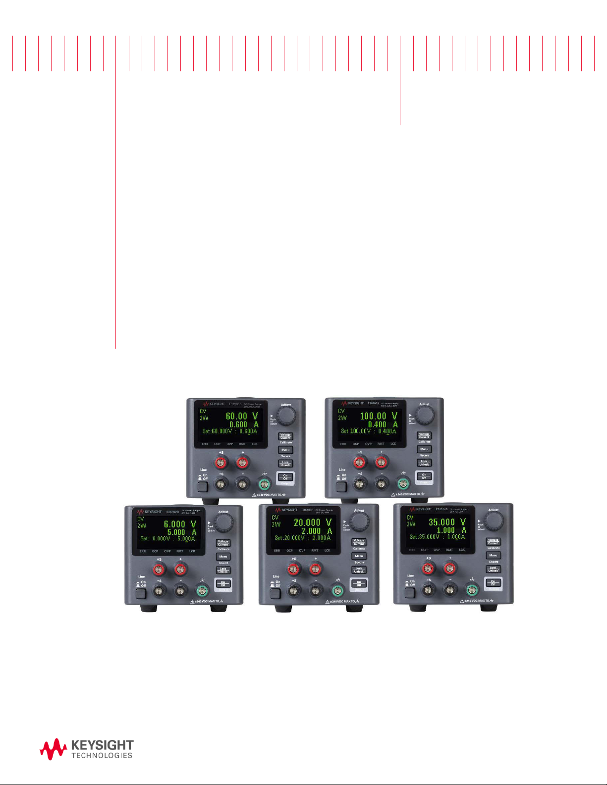
The Keysight E36100B Series is a series of DC bench and system power supplies with the following features and
characteristics:
– Single output up to 100 V or 5 A
– Small size: two rack-units (2U), 1/4-rack form factor
– Remote sense capability
– Intuitive front panel
– High visibility organic light emitting diode (OLED)display
– High performance functionality: accuracy, transient response, and rise/fall time
– LAN (LXICore) and USB interfaces for remote programming with SCPIS
Front panel
Item Description
A Tough carrying handle
B Information-packed, high-contrast OLED display; easily viewable even from sharp angles
C Rotary knob for quick and easy configuration
D Fast voltage/current setting and front-panel electronic calibration
E Menu key opens intuitive user interface
F Front-panel lock prevents accidental changes during tests
G Output enable/disable switch to protect your DUT quickly
H Dual-position power switch
I Sense terminals
J Output terminals
K Earth ground reference point
Keysight E36100B Series Operating and Service Guide 14
Page 15

Rear panel
The rear panel includes the power input, standard LAN and USB ports, and a security slot. Always use the power
cord that arrived with the instrument or one with equivalent ratings.
15
Keysight E36100B Series Operating and Service Guide
Page 16
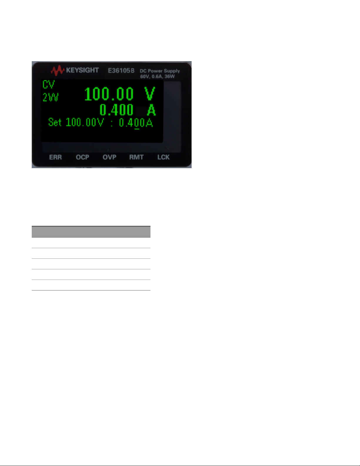
Display
The power supply's front panel features a high-visibility OLED display.
The upper left corner of the display shows either CV or CC to indicate that the instrument is in constant voltage or
constant current mode. Below that is either 2W or 4W, to indicate whether 2-wire (normal) or 4-wire (remote
sensing) measurement is in use. The right side of the display shows the output voltage and current (when the output
is enabled), and the voltage and current settings are shown near the bottom of the screen.
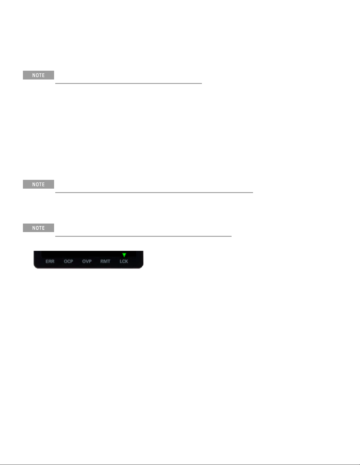
The very bottom of the screen can show arrows, each of which represents a different annunciator.
Label Meaning
ERR An error has occurred.
OCP An overcurrent protection event has occurred.
OVP An overvoltage protection event has occurred.
RMT The instrument is being programmed remotely.
LCK The front panel is locked.
Keysight E36100B Series Operating and Service Guide 16
Page 17
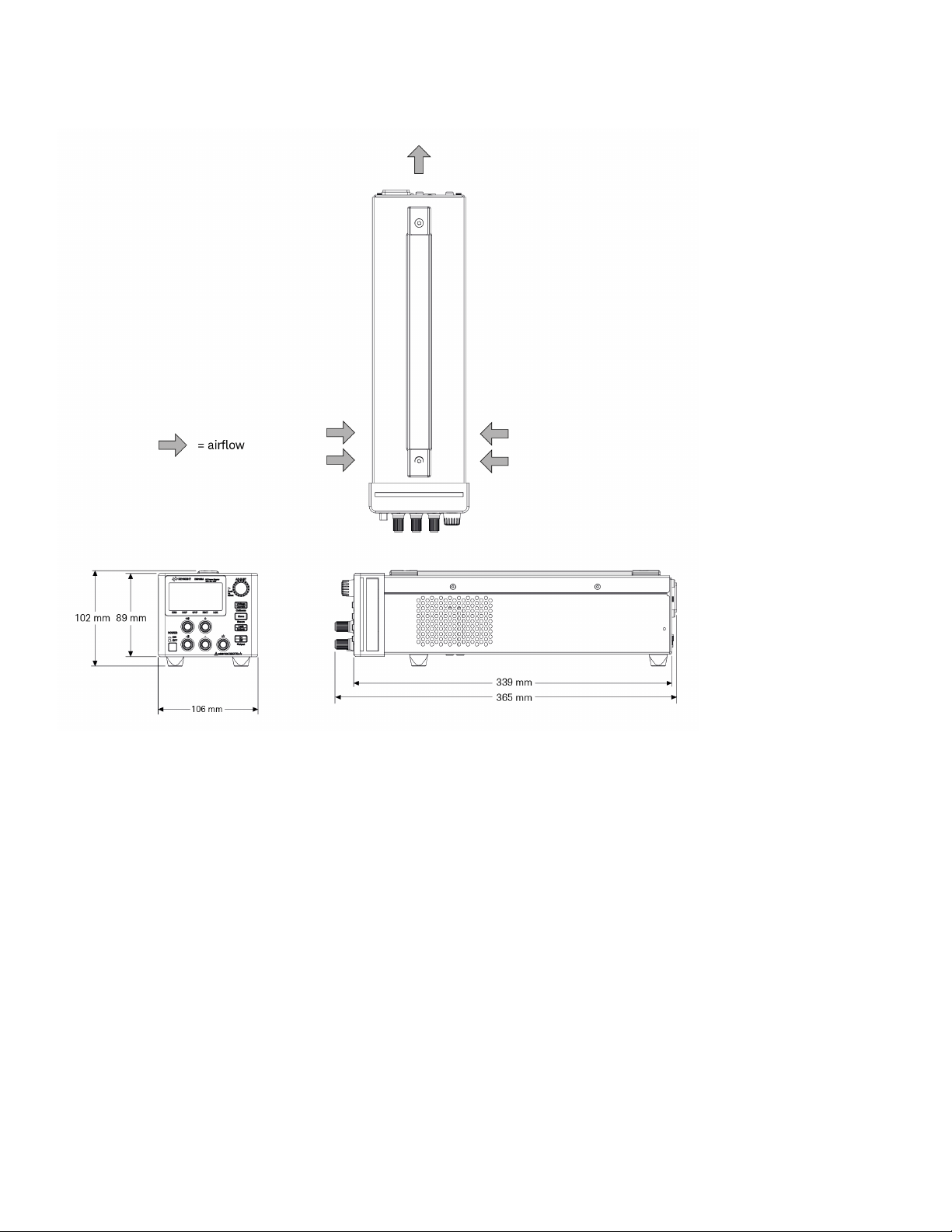
Dimension diagram
Setup the instrument
Place the instrument's feet on a flat, smooth horizontal surface. Connect output and sense leads to the front panel,
being careful not to short the leads together. Attach the power cable to the rear panel, then plug it into main power.
Connect LAN or USB cables as desired, and you may also secure the instrument with a security lock cable.
Before disconnecting cables and cords from the instrument, turn the instrument off using the front-panel power
switch and disconnect from the supply source by unplugging the detachable power cord.
17
Keysight E36100B Series Operating and Service Guide
Page 18

Options and Fuse Information
Ensure you order the proper instrument option for the mains power that will be used for the instrument.
Options 0EM, 0E3, and 0E9 determine which power-line voltage is selected at the factory. The default is configured
for 230 VAC ± 10%, 47-63 Hz input voltage (option 0E3).
Option Description
0EM 115 VAC ± 10%, 47-63 Hz input voltage
0E3 230 VAC ± 10%, 47-63 Hz input voltage
0E9 100 VAC ± 10%, 47-63 Hz input voltage
Input power for E36102B, E36103B, E36104B, E36105B, and E36106B is 200 VA maximum.
Ensure the correct AC input voltage and fuse settings
Use the proper switch settings
To change the input AC voltage selector on the power supply, use the two AC selector switches on the underside of
the power supply as shown.
For example, to select 230 V, slide the left switch to the left and the right switch to the right, as illustrated in the
diagram below the switches.
To select 115 V, slide both switches to the right, and to select 100 V, slide the two switches towards each other.
Keysight E36100B Series Operating and Service Guide 18
Page 19
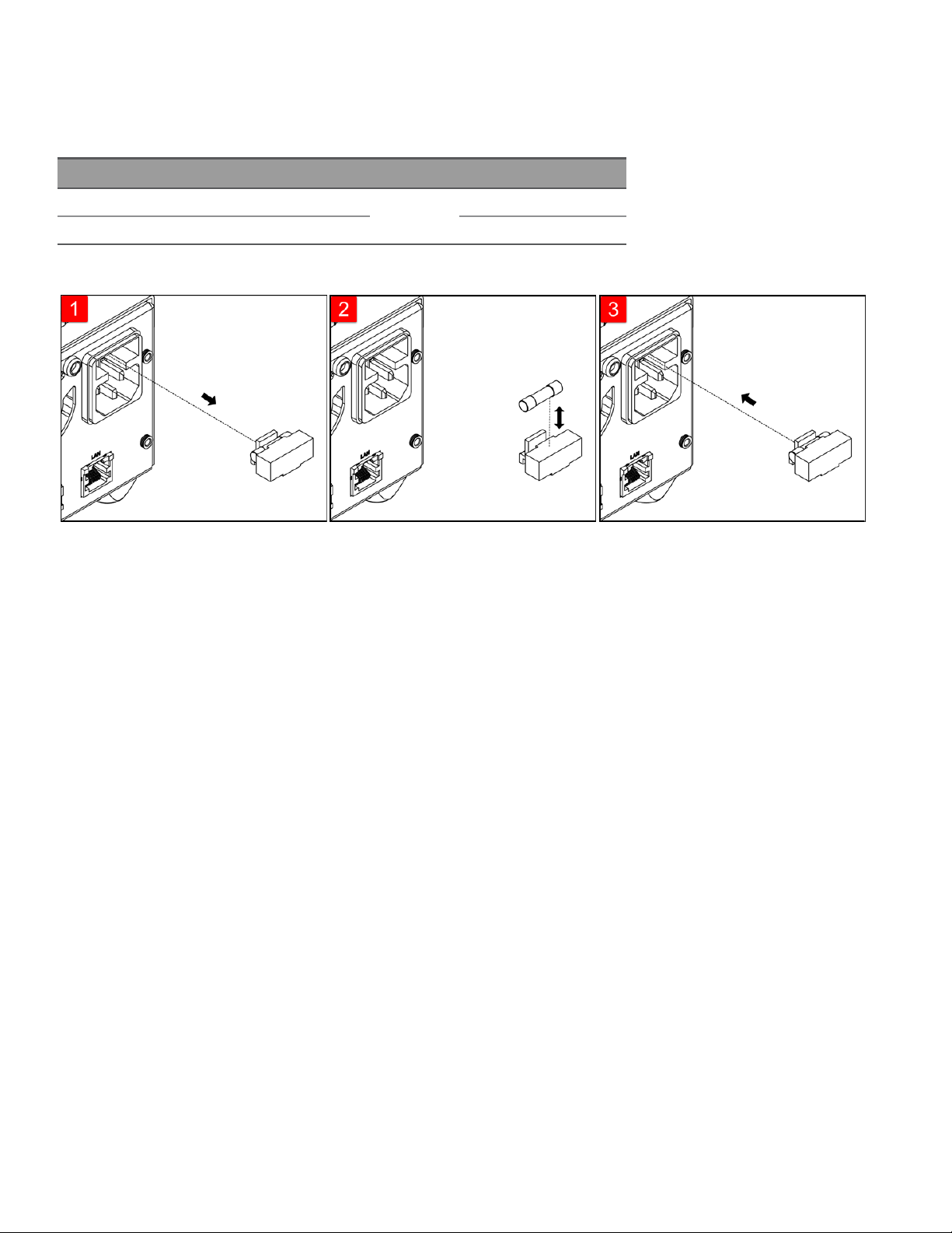
Use the correct fuse
You must use a time delay 2-A fuse for 100- and 115-VAC inputs, and a time delay1-A fuse for 230-VAC inputs:
Part Number Description Manufacturer Application
2110-1639 Fuse 1 A, 250 V Time-delay Littelfuse 230-V line voltage
2110-1640 Fuse 2 A, 250 V Time-delay 100- and 115-V line voltage
To configure the correct fuse, follow the three steps shown below:
Pull the fuse holder out of the
power supply.
Remove and insert the proper
fuse into the fuse holder.
Re-insert the fuse holder into the
power supply.
19
Keysight E36100B Series Operating and Service Guide
Page 20

Programming Ranges
The following table shows the maximum voltage, current, and power that can be programmed for each model. The
DEFault voltage is always 0 V.
Model Max voltage (V) Max current (A) Max power(W)
E36102B 6 5.0 30
E36103B 20 2.0 40
E36104B 35 1.0 35
E36105B 60 0.6 36
E36106B 100 0.4 40
Note that the actual programmable values are 3% above these nominal values, but instrument specifications are
only guaranteed up to the values shown in this table.
Table of programming and readback resolutions
Model Voltage programming Voltage readback Current programming Current readback Small current readback
E36102B 0.001 V 0.001 V 0.001 A 0.001 A 0.001 mA
E36103B 0.001 V 0.001 V 0.001 A 0.001 A 0.001 mA
E36104B 0.001 V 0.001 V 0.001 A 0.001 A 0.001 mA
E36105B 0.001 V 0.01 V 0.001 A 0.0001 A 0.001 mA
E36106B 0.001 V 0.01 V 0.001 A 0.0001 A 0.001 mA
Keysight E36100B Series Operating and Service Guide 20
Page 21

Extending the Voltage Range and Current Range
The power supply may be able to provide voltages and currents greater than its rated maximum outputs if the
power- line voltage is at or above its nominal value.
Operation can be extended up to 3% over the rated output without damage to the power supply, but performance
cannot be guaranteed to meet specifications in this region. If the power- line voltage is maintained in the upper end
of the input voltage range, the power supply willprobably operate within its specifications. The power supply is more
likely to stay within specifications if only one of the voltage or current outputs is exceeded.
Series connections
You can connect up to four E36100B Series power supplies up to the output isolation rating of any one supply to
obtain a higher voltage than a single power supply can produce. Series-connected power supplies can be operated
with one load across both power supplies or with a separate load for each power supply. The power supply has a
reverse polarity diode connected across the output terminals so that if operated in series with other power supplies,
damage will not occur if the load is short-circuited or if one power supply is turned on separately from its series
partners.
When the series connection is used, the output voltage is the sum of the voltages of the individual power supplies.
The current is the current of any one power supply. Each of the individual power supplies must be adjusted in order
to obtain the total output voltage.
Parallel connections
You can connect up to four E36100B Series power supplies in parallelto obtain a total output current greater than
a single power supply can produce. The total output current is the sum of the output currents of the individual
power supplies. The output of each power supply can be set separately. The output voltage controls of one power
supply should be set to the desired output voltage; the other power supply should be set for a slightly higher output
voltage. The supply with the higher output voltage setting will deliver its constant current output, and drop its
output voltage until it equals the output of the other supply, and the other supply will remain in the constant voltage
operation and only deliver that fraction of its rated output current which is necessary to fulfill the total load demand.
21
Keysight E36100B Series Operating and Service Guide
Page 22

Front Panel Operation
This section describes how to perform the following operations from the instrument's front panel.
Configure the LAN interface
Set voltage and current
Specify 2- or 4-wire measurement
Configure Overcurrent Protection (OCP) and Overvoltage Protection (OVP)
Clear an OCP or OVP event
Clear an overtemperature protection (OTP) event
Lock and unlock the front panel
Save or recall the instrument's state
Configure the Power-on State
Read error codes
Configure the LAN interface
You should generally be able to connect to the LAN by simply connecting the LAN cable and turning the instrument
on. However, you can use the procedure below if you want to specify connections other than the default values or if
you need to see what a given value is. This section provides procedures for viewing and changing LANsettings.
1. Press [Menu].
2. Turn the knob to I/O Config and press the knob.
3. Turn the knob to LAN and press the knob.
4.
Turn the knob to the desired IP Address to a value of the form xxx.xxx.xxx.xxx, where each xxx represents a base
10 number from 0 to 255. Press [Voltage/Current] to move between numbers, then press the knob to finish.
5.
The instrument will briefly display CHANGE SAVED to indicate success.
6.
Turn the knob to the desired Subnet address using the same method with which you set the IP Address. Then
press the knob to select.
7.
The instrument will briefly display CHANGE SAVED to indicate success.
8.
Turn the knob to the desired Gateway address. Then press the knob to select.
9.
The instrument will briefly display CHANGE SAVED to indicate success.
10. Press [Menu] to exit the menu system.
Keysight E36100B Series Operating and Service Guide 22
Page 23

Set voltage and current
If you are in a menu, you must exit the menu before setting the voltage and current.
1. Press [Voltage / Current].
2.
Turn the knob to the desired voltage value, pushing the knob to move between digits.
3. Press [Voltage / Current].
4.
Turn the knob to the desired current value, pushing the knob to move between digits.
5. Press [Voltage / Current].
6. If the display currently shows OFF, press [Output On / Off] to enable the output. Press this key again to turn the
output off.
Constant voltage and constant current
If the output load resistance exceeds the voltage setting divided by the current setting, the instrument will operate
in constant voltage mode. The current will equal the voltage divided by the load resistance.
If the output load resistance is less than the voltage setting divided by the current setting, the instrument will
operate in constant current mode. The voltage will equal the current multiplied by the load resistance.
Specify 2- or 4-wire measurement
You have the option to use the remote sense terminals on the front panel to measure the voltage at the device
under test (DUT). To specify whether you want to use this option:
1. Press [Menu].
2. Turn the knob to Sense Setting and press the knob.
3. Turn the knob to Internal or External and press the knob.
The internal setting sets a relaywithin the power supply to connect the output and sensing connector. This means
that only two wires are used; and remote sensing is disabled. The external setting sets a relay within the power
supply to disconnect the output and remote sensing inputs. This means that four wires are used; and remote
sensing is enabled.
23
Keysight E36100B Series Operating and Service Guide
Page 24

Configure Overcurrent Protection (OCP) and Overvoltage Protection (OVP)
1. Press [Menu].
2. Turn the knob to OCP Set or OVP Set and press the knob.
3.
Press the knob again to choose OCP Delay or OVP Level.
4.
Turn the knob to the desired OCP or OVPlimit value. Then press the knob.
5. Turn the knob to OCP On, OCP Off, OVPOn, or OVP Off and press the knob to enable or disable OCP or OVP.
6. Turn the knob to Exit Menu and press the knob.
If OCP or OVP is enabled, the instrument will display a triangle above the OCP or OVP annunciator.
Clear an OCP or OVP event
The instrument prominently displays an OCPTRIPPED or OVPTRIPPEDmessage to indicate an overcurrent or
overvoltage event. The triangle above OCP or OVP flashes continuously until the event is cleared.
The output will be automatically turned OFF when OCP/OVP occurs.
1.
To begin, correct the condition that caused the OCP or OVP event. There are three ways to do this:
a.
Turn off OCP or OVP as described above.
b.
Set the current or voltage level to be less than the OCP or OVP level. You may be able to do this by adjusting
the voltage setting, the current setting, or the resistance of the load.
c.
Set the OCP or OVP limit value to be above the current or voltage level.
2. Press [Menu].
3. Turn the knob to OCP Set or OVP Set and press the knob.
4.
Turn the knob to the desired OCP or OVP limit value (if it needs to be changed). Then press the knob.
5. Turn the knob to OCP Clear or OVP Clear and press the knob.
Keysight E36100B Series Operating and Service Guide 24
Page 25
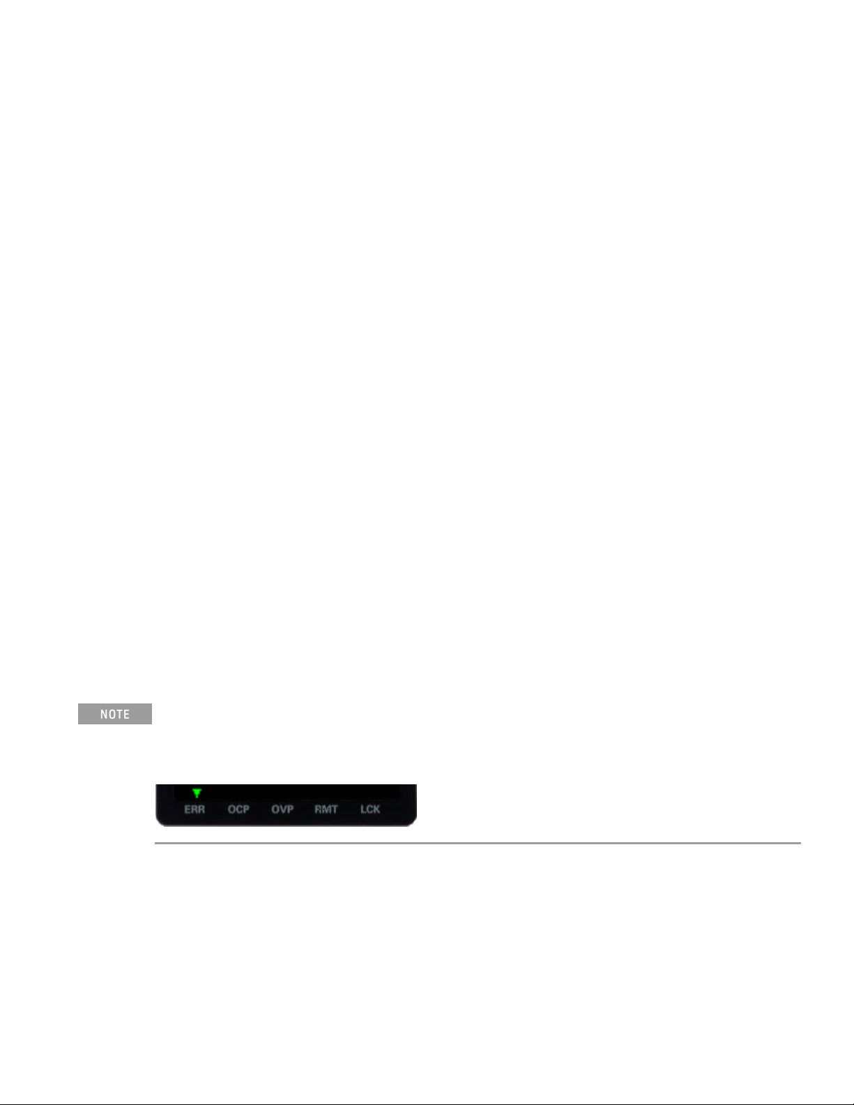
Clear an overtemperature protection (OTP) event
The instrument prominently displays an OTPTRIPPED message to indicate an OTP event. In addition, the triangle
above ERR will flash continuously until the error event is cleared.
The output will be automatically turned OFF when OTP occurs.
The overtemperature event willbe logged in the Error list, and you must clear the OTP event before the output can
be turned ON again.
1.
To begin, correct the condition that caused the OTP event and allow the instrument to cool.
2. Press [Menu].
3. Turn the knob to Error and press the knob. The instrument will briefly display a message like 3 ERRORS (the
number will vary) to indicate how many errors are in the queue.
4.
Turn the knob to cycle through the error codes, recording them as you go. Press the knob to view the error
description. Press [Menu] to exit and clear the error list.
An OTP event will occur again after it is cleared if the instrument remains overheated.
Lock and unlock the front panel
If you are in a menu, you must exit the menu before locking the front panel.
1. Press [Lock / Unlock] to lock the front panel. This produces an LCK annunciator triangle, as shown below.
2.
If you press a key after the front panel is locked, the display will read HOLDKEY. That message indicates that
you must press and hold the [Lock / Unlock] key to unlock the front panel and clear the LCK triangle.
25
Keysight E36100B Series Operating and Service Guide
Page 26
Save or recall the instrument's state
The instrument allows you to save and recall the instrument state in one of 10 memory locations, labeled
0through9. This allows you to quickly configure the instrument for commonly used applications.
An instrument state includes the instrument's output enable status, voltage and current settings, and OCP and OCV
settings. It does not include error codes or LAN configuration information.
To save or recall the instrument state
1. Press [Menu].
2. Turn the knob to Store (or Recall) and press the knob.
3. Turn the knob to an option from Store 0 to Store 9 (or Recall 0 to Recall 9) and press the knob to store or
recall the present state of the instrument in the specified memory location.
4.
The instrument will briefly display DONE.
Configure the Power-on State
The instrument allows you to recallthe power-on state as either the default (*RST) state or the state stored in one of
10 memory locations (0through9). To configure the power-on state:
1. Press [Menu].
2. Turn the knob to Power-on and press the knob.
3.
Turn the knob to Default, or a state from Recall 0 to Recall 9 and press the knob to make your selection.
4.
The instrument will briefly display CHANGED SAVED if the recall state is different from the previous state, and
NOCHANGE if the same state was selected.
Read error codes
You only need to do this if there is a triangle over
sure to follow the procedure below carefully, and record each error code in order. Once you exit this menu, there is
no way to retrieve the error codes again.
1. Press [Menu].
2. Turn the knob to Error and press the knob. The instrument will briefly display a message like 3 ERRORS (the
number will vary) to indicate how many errors are in the queue.
in the lower left corner of the screen, as shown below. Be
ERR
3.
Turn the knob to cycle through the error codes, recording them as you go.
Keysight E36100B Series Operating and Service Guide 26
Page 27
Remote Control
You can control the instrument remotely in two ways. To program the instrument via SCPI, use Keysight IO
Libraries. To control the instrument via a simulated front panel, use the instrument's Web interface.
Keysight IOLibraries Suite
Keysight IOLibraries Suite is a collection free instrument control software that automatically discovers instruments
and allows you to control instruments over the LAN, USB, GPIB, RS-232, and other interfaces.
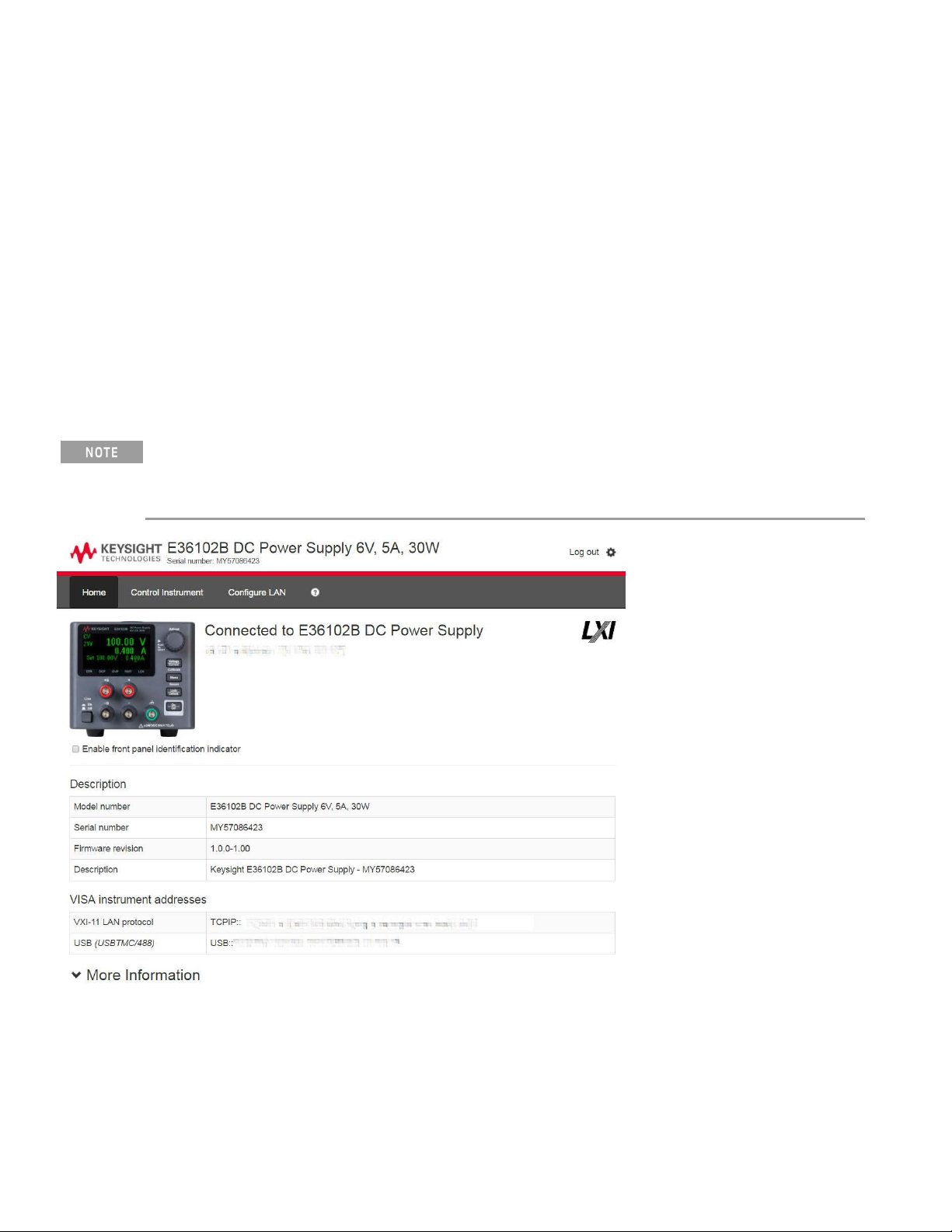
E36100B Series Web interface
You can monitor control the instrument from a Web browser by using the instrument's Web interface. To connect,
simply enter the instrument's IP address or hostname in your browser's address bar and hit Enter.
If you see an error indicating 400: Bad Request, that is related to an issue with "cookies" in your Web browser. To
avoid this issue, either start the Web interface by using the IPaddress (not host name) in the address bar), or clear
cookies from your browser immediately before starting the Web interface.
Check the checkbox below the picture of the instrument to enable an indicator on the instrument's front panel. This
is helpful if you have severalE36100B Series instruments and you wish to identify the one to which you are
connected.
The Configure LANtab on the top allows you to change the instrument's LAN parameters; exercise caution when
doing so, as you may interrupt your ability to communicate with the instrument.
27
Keysight E36100B Series Operating and Service Guide
Page 28
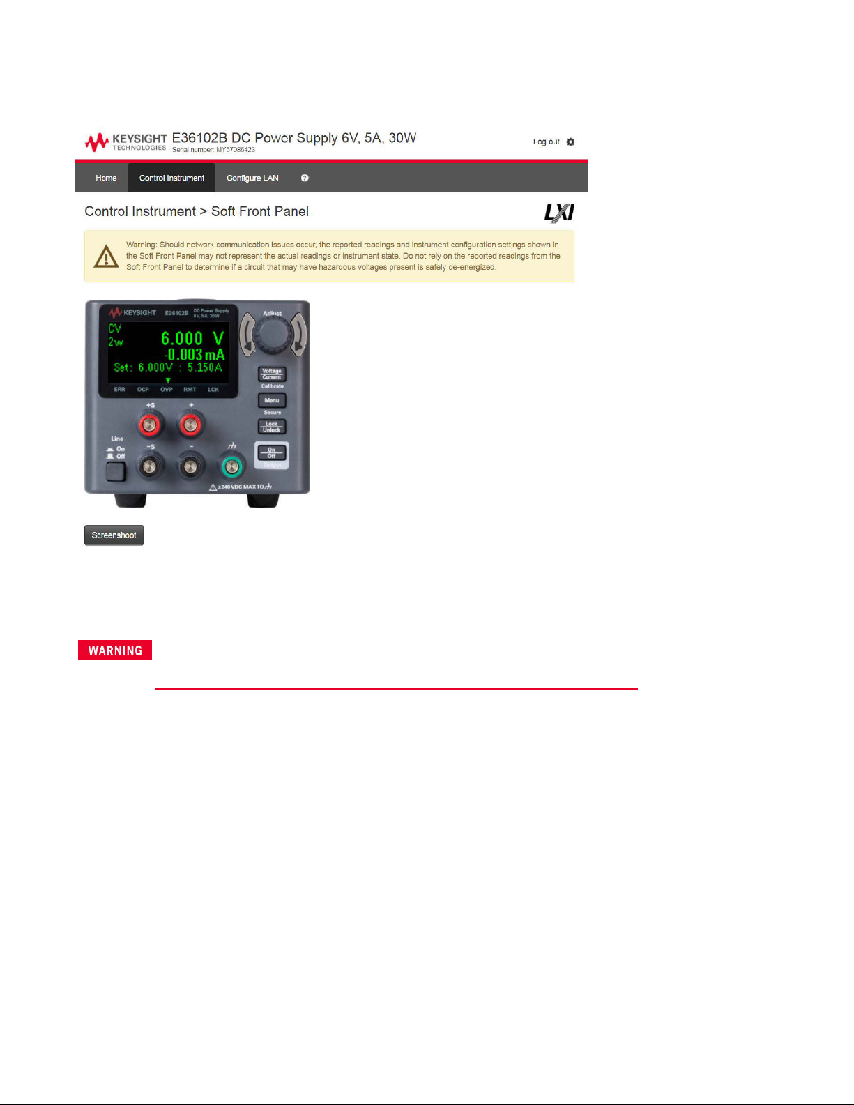
When you click the Control Instrument tab, the instrument will ask you for a password (default is keysight, all lower
case), and then it will open a new page, shown below.
This interface allows you to use the instrument just as you would from the front panel. Note the curved arrow keys
that allow you to "turn" the knob. You can click the knob to "push" it, just as you would push any of the other keys
on the front panel.
Read warning
Be sure to read and understand the warning at the top of the Control Instrument page.
Keysight E36100B Series Operating and Service Guide 28
Page 29

Technical connection details
In most cases, you can easily connect to the instrument with the IO Libraries Suite or Web interface. In certain
circumstances, it may be helpful to know the following information.
Interface Details
VXI-11
LAN
Web UI Port number 80, URL http://<IP address>/
VISA String: TCPIP0::<IP Address>::inst0::INSTR
Example: TCPIP0::192.168.10.2::inst0::INSTR
USB0::0x2A8D::<Prod ID>::<Serial Number>::0::INSTR
Example: USB0::0x2A8D::0x0902::MY55160003::0::INSTR
The vendor ID: 0x2A8D, the product ID is 0x0902, and the instrument serial number is MY55160003.
The product ID varies by model: 0x0602 (E36102B), 0x0702 (E36103B), 0x0802 (E36104B), 0x0902 (E36105B), 0x0A02 (E36106B).
Using sockets
Power supplies allow data socket to be made.
Keysight instruments have standardized on using port 5025 for SCPI socket services. A data socket on this port can
be used to send and receive ASCII/SCPI commands, queries, and query responses. All commands must be
terminated with a newline for the message to be parsed. All query responses will also be terminated with a newline.
29
Keysight E36100B Series Operating and Service Guide
Page 30

Rack Mounting the Instrument
Use the Rack Mount kit as stated below to rack mount the instrument. Installation instructions are provided with the
rack mount kit.
Be sure to use the support rails in the rack cabinet.
To prevent overheating, do not block airflow to or from the instrument. Allow enough clearance at the rear, sides,
and bottom of the instrument to permit adequate internal air flow.
The power supply can be mounted in a standard 19-inch rack cabinet. They are designed to fit in two rack-units
(2U) of space.
Remove the feet before rack mounting the unit. Do not block the air intake and exhaust at the sides and rear of the
unit.
Rack mounting a single instrument
To rack mount a single instrument, order E36102-66502.
Rack mounting multiple instruments side-by-side
Rack mount kit with flange for 2 units (E36102-66503)
Rack mount kit with flange for 4 units (E36102-66505)
Rack mount kit with flange for 3 units (E36102-66504)
Rack mount kit with flange and handles for 4 units
(E36102-66506)
30
Keysight E36100B Series Operating and Service Guide
Page 31

31
Keysight E36100B Series Operating and Service Guide
Page 32

2 SCPI Programming
Introduction to the SCPI Language
Error Messages
SCPI Status Registers
APPLy Subsystem
CALibration Subsystem
CURRent Subsystem
DISPlay Subsystem
IEEE-488 Subsystem
MEASure Subsystem
OUTPut Subsystem
STATus Subsystem
SYSTem Subsystem
Triggering Commands
VOLTage Subsystem
This chapter describes the programming information for the E36100B
Series programmable DC power supplies.
Keysight E36100B Series Operating and Service Guide 32
Page 33

Introduction to the SCPI Language
Standard Commands for Programmable Instruments (SCPI) is an ASCII- based instrument command language
designed for test and measurement instruments. Refer to Simplified Programming Overview for basic techniques for
programming the power supply over the remote interface.
SCPI commands are based on a hierarchical structure, also known as a tree system. In this system, associated
commands are grouped together under a common node or root, thus forming subsystems. A portion of the
SOURce subsystem is shown below to illustrate the tree system.
[SOURce:]
CURRent {<current>|MIN|MAX|UP|DOWN} CURRent? [MIN|MAX]
CURRent:
TRIGgered {<current>|MIN|MAX} TRIGgered? {MIN|MAX}
VOLTage {<voltage>|MIN|MAX|UP|DOWN} VOLTage? [MIN|MAX]
VOLTage:
TRIGgered {<voltage>|MIN|MAX} TRIGgered? {MIN|MAX}
SOURce is the root keyword of the command, CURRent and VOLTage are second-level keywords, and TRIGgered is
the third- level keyword. A colon (:) separates a command keyword from a lower- levelkeyword.
33
Keysight E36100B Series Operating and Service Guide
Page 34

Command format used in this manual
The format used to show commands in this manual is shown below:
CURRent {<current>|MINimum|MAXimum|UP|DOWN}
The command syntax shows most commands (and some parameters) as a mixture of upper- case and lower- case
letters. The upper- case letters indicate the abbreviated spelling for the command. For shorter program lines, send
the abbreviated form. For better program readability, send the long form.
For example, in the above syntax statement, CURR and CURRENT are both acceptable forms. You can use uppercase or lower- case letters. Therefore, CURRENT, curr, and Curr are allacceptable. Other forms, such as CUR and
CURREN, will generate an error.
Braces ({}) enclose the parameter choices for a given command string. The braces are not sent with the command
string.
A vertical bar (|) separates multiple parameter choices for a given command string.
Triangle brackets (<>) indicate that you must specify a value for the enclosed parameter. For example, the above
syntax statement shows the current parameter enclosed in triangle brackets. The brackets are not sent with the
command string. You must specify a value for the parameter (such as CURR 0.1).
Some parameters are enclosed in square brackets ([]). The brackets indicate that the parameter is optional and can
be omitted. The brackets are not sent with the command string. If you do not specify a value for an optional
parameter, the power supply chooses a default value.
A colon (:) separates a command keyword from a lower-levelkeyword. You must insert a blank space to separate a
parameter from a command keyword. If a command requires more than one parameter, you must separate
adjacent parameters using a comma as shown below:
SOURce:CURRent:TRIGgered
APPLy 3.5,1.5
Keysight E36100B Series Operating and Service Guide 34
Page 35

Command separators
A colon (:) separates a command keyword from a lower- levelkeyword as shown below:
SOURce:CURRent:TRIGgered
A semicolon (;) is used to separate two commands within the same subsystem, and can also minimize typing. For
example, sending the following command string,
SOUR:VOLT MIN;CURR MAX
is the same as sending the following two commands:
SOUR:VOLT MIN
SOUR:CURR MAX
Use a colon and a semicolon to link commands from different subsystems. For example, in the following command
string, an error is generated if you do not use the colon and semicolon:
DISP:TEXT:CLE;:SOUR:CURR MIN
Using the MIN and MAX parameters
You can substitute MINimum or MAXimum in place of a parameter for many commands. For example, consider the
following command:
CURRent {<current>|MIN|MAX}
Instead of selecting a specific current, you can substitute MINimum to set the current to its minimum value or
MAXimum to set the current to its maximum value.
Querying parameter settings
You can query the value of most parameters by adding a question mark (?) to the command. For example, the
following command sets the output current to 5 A:
CURR 5
You can query the value by executing:
CURR?
You can also query the maximum or minimum value allowed with the present function as follows:
CURR? MAX CURR? MIN
If you send two query commands without reading the response from the first, and then attempt to read the second
response, you may receive some data from the first response followed by the complete second response. To avoid
this, do not send a query command without reading the response. When you cannot avoid this situation, send a
device clear before sending the second query command.
35
Keysight E36100B Series Operating and Service Guide
Page 36

SCPI command terminators
A command string sent to the power supply must terminate with a <new line> character. The IEEE- 488 EOI (endor-identify) message is interpreted as a <new line> character and can be used to terminate a command string in
place of a <new line> character. A <carriage return> followed by a <new line> is also accepted. Command string
termination will always reset the current SCPI command path to the root level. The <new line> character has the
ASCII decimal code of 10.
IEEE-488.2 common commands
The IEEE- 488.2 standard defines a set of common commands that perform functions like reset, self- test, and
status operations. Common commands always begin with an asterisk (*), are four to five characters in length, and
may include one or more parameters. The command keyword is separated from the first parameter by a blank space.
Use a semicolon (;) to separate multiple commands as shown below:
*RST; *CLS; *ESE 32; *OPC?
SCPI parameter types
The SCPI language defines several different data formats to be used in program messages and response messages.
Numeric parameters
Commands that require numeric parameters will accept all commonly used decimal representations of numbers
including optional signs, decimal points, and scientific notation. Special values for numeric parameters like
MINimum, MAXimum, and DEFault are also accepted.
You can also send engineering unit suffixes (V, A, or SEC) with numeric parameters. If only specific numeric values
are accepted, the power supply will automaticallyround the input numeric parameters. The following command
uses a numeric parameter:
CURR {<current>|MIN|MAX|UP|DOWN}
Discrete parameters
Discrete parameters are used to program settings that have a limited number of values such as BUS and IMM. Query
responses will always return the short form in all upper- case letters. The following command uses discrete
parameters:
TRIG:SOUR {BUS|IMM}
Boolean parameters
Boolean parameters represent a single binary condition that is either true or false. For a false condition, the power
supply will accept OFF or 0. For a true condition, the power supply will accept ON or 1. When you query a boolean
setting, the power supply will always return 0 or 1. The following command uses a boolean parameter:
DISP {OFF|ON}
Keysight E36100B Series Operating and Service Guide 36
Page 37

String parameters
String parameters can contain virtually any set of ASCII characters. A string must begin and end with matching
quotes; either with a single quote or with a double quote. You can include the quote delimiter as part of the string
by typing it twice without any characters in between. The following command uses a string parameter:
DISP:TEXT <quoted string>
37
Keysight E36100B Series Operating and Service Guide
Page 38

Error Messages
The instrument returns error messages in accordance with the SCPI standard.
—
Up to 20 errors can be stored in the instrument's error queue, and the triangle annunciator above ERR turns on
when one or more errors are in the error queue.
— Error retrieval is first-in-first-out (FIFO), and errors are cleared as you read them. When you have read all errors
from the error queue, the ERR annunciator turns off.
— If more than 20 errors have occurred, the last error stored in the queue (the most recent error) is replaced with -
350,"Queue overflow". No additional errors are stored until you remove errors from the queue. If no errors have
occurred when you read the error queue, the instrument responds with +0,"No error".
— Send SYSTem:ERRor? to read the most recent error. Each error is in the format: -104,"Data type error".
—
To read the error queue from the front panel, press [Menu], then turn the knob to Error and press the knob to
select it. Then rotate the knob to view the error codes. Be sure to record the error messages, because they will be
cleared when you exit the error list.
— The error queue is cleared by power cycles and *CLS., but not *RST.
Error codes
The instrument's error codes are listed below:
-440,"Query UNTERMINATED after indefinite response"
-430,"Query DEADLOCKED"
-420,"Query UNTERMINATED"
-410,"Query INTERRUPTED"
-400,"Query error"
-363,"Input buffer overrun"
-350,"Queue overflow"
-330,"Self-test failed"
-310,"System error"
-277,"Macro redefinition not allowed"
-276,"Macro recursion error"
-273,"Illegal macro label"
-272,"Macro execution error"
-270,"Macro error"
-241,"Hardware missing"
-230,"Data corrupt or stale"
Keysight E36100B Series Operating and Service Guide 38
Page 39

-225,"Out of memory"
-224,"Illegal parameter value"
-223,"Too much data"
-222,"Data out of range"
-221,"Settings conflict"
-213,"Init ignored"
-211,"Trigger ignored"
-200,"Execution error"
-183,"Invalid inside macro definition"
-181,"Invalid outside macro definition"
-178,"Expression data not allowed"
-171,"Invalid expression"
-170,"Expression error"
-168,"Block data not allowed"
-161,"Invalid block data"
-158,"String data not allowed"
-151,"Invalid string data"
-150,"String data error"
-148,"Character data not allowed"
-141,"Invalid character data"
-138,"Suffix not allowed"
-134,"Suffix too long"
-131,"Invalid suffix"
-128,"Numeric data not allowed"
-124,"Too many digits"
-123,"Exponent too large"
-121,"Invalid character in number"
-114,"Header suffix out of range"
-113,"Undefined header"
-112,"Program mnemonic too long"
39
Keysight E36100B Series Operating and Service Guide
Page 40

-109,"Missing parameter"
-108,"Parameter not allowed"
-105,"GET not allowed"
-104,"Data type error"
-103,"Invalid separator"
-102,"Syntax error"
-101,"Invalid character"
-100,"Command error"
514,"LAN config error"
561,"Analog board - failed to save to EEPROM"
564,"Analog board - failed to load from EEPROM"
565,"Analog board - over temperature"
566,"Analog board - command timed out"
601,"Front panel does not respond"
609,"System ADC test failed"
610,"I/O board not plugged in"
611,"Unsupported I/O board"
612,"Analog board does not respond"
613,"Analog bias output ±15V test failed"
614,"EEPROM test failed"
615,"EEPROM save failed"
616,"Model no mismatched"
630,"Fan test failed"
631,"System DAC test failed"
701,"Cal security disabled by jumper"
702,"Invalid state. Cal secured"
703,"Invalid secure code"
704,"Secure code too long"
708,"Cal output disabled"
717,"Cal OVP or OCP status enabled"
Keysight E36100B Series Operating and Service Guide 40
Page 41

721,"Failed to calibrate voltage DAC"
722,"Failed to calibrate voltage ADC"
723,"Failed to calibrate OVP"
724,"Failed to calibrate current DAC"
725,"Failed to calibrate current ADC"
726,"Failed to calibrate OCP"
727,"Invalid Calibration sequence"
728,"Calibration failed"
41
Keysight E36100B Series Operating and Service Guide
Page 42

SCPI Status Registers
All SCPI instruments implement status registers in the same way. The status system records various instrument
conditions in three register groups: the Status Byte register, the Standard Event register, and the Questionable
Status register groups. The Status Byte register records high-level summary information reported in the other
register groups.
What is an event register?
An event register is a read-only register that reports defined conditions within the instrument. Bits in an event
register are latched. Once an event bit is set, subsequent state changes are ignored. Bits in an event register are
automaticallycleared by a query of that register (such as *ESR? or STAT:QUES:EVEN?) or by sending the *CLS (clear
status) command. A reset (*RST) or device clear will not clear bits in event registers. Querying an event register
returns a decimal value corresponding to the binary-weighted sum of all bits set in the register.
What is an enable register?
An enable register defines which bits in the corresponding event register are logically ORed together to form a single
summary bit. Enable registers are both readable and writable. Querying an enable register will not clear it. The *CLS
(clear status) command does not clear enable registers but it does clear the bits in the event registers. To enable bits
in an enable register, you must write a decimal value which corresponds to the binary- weighted sum of the bits you
wish to enable in the register.
Keysight E36100B Series Operating and Service Guide 42
Page 43

Standard Event Status Enable Register
Bit Value Name Description
0 1 OPC Operation complete
1 2 (unused) (reserved for future use)
2 4 QYE Query error
3 8 DDE Device dependent error
4 16 EXE Execution error
5 32 CME Command error
6 64 (unused) (reserved for future use)
7 128 PON Power-on
Operation Status Register
Bit Value Name Description
0 1 CAL The output is computing new calibration constants
1-4 2-16 (unused) (reserved for future use)
5 32 WTG The output is waiting for a trigger.
6-7 64-128 (unused) (reserved for future use)
8 256 CV The output is in constant voltage mode.
9 512 (unused) (reserved for future use)
10 1024 CC The output is in constant current mode.
Questionable Register
Bit Value Name Description
0 1 OV Output disabled by overvoltage protection
1 2 OC Output disabled by overcurrent protection
2-3 4-8 (unused) (reserved for future use)
4 16 OT Output disabled by overtemperature protection
5-9 32-512 (unused) (reserved for future use)
10 1024 UNR Output is unregulated
43
Keysight E36100B Series Operating and Service Guide
Page 44

Keysight E36100B Series Operating and Service Guide 44
Page 45

APPLy Subsystem
APPLy <voltage>| DEFault | MINimum | MAXimum[,<current>| DEFault | MINimum | MAXimum]
APPLy?
Specifies and changes the output voltage and current in one command.
– The DEFault, MINimum, and MAXimum values for each mode are shown in Programming Ranges.
– The query returns a quoted string with the voltage setting before the current setting.
– Both values returned by the query have five decimal points: "25.00000,0.75000"
45
Keysight E36100B Series Operating and Service Guide
Page 46

CALibration Subsystem
For a detailed discussion on the calibration procedures, see Calibration Adjustment Procedures.
CALibration:COUNt?
Returns the number of times the instrument has saved calibration data as a signed whole number, for example +21.
Your instrument was calibrated at the factory; read and record the initial count when you receive the instrument.
CALibration:CURRent[:DATA][:HIGH] <value>
Enters an output current value (in amps) that you obtained by reading a DMM. You must first select a calibration
level (CAL:CURR:LEV) for the value being entered. This command can only be used when calibration is unsecured
and output is ON.
CALibration:CURRent[:DATA]:LOW <value>
Enters an output current value (in amps) that you obtained by reading a DMM. This is similar to
CALibration:CURRent[:DATA][:HIGH], but it is only used for small current calibration. This command can only be
used when calibration is unsecured and output is ON.
CALibration:CURRent:LEVel[:HIGH] MINimum|MAXimum
Initiates calibration for a specific current level. The MINimumcalibration must be performed before the MAXimum,
and you must unsecure this instrument to use this command.
CALibration:CURRent:LEVel:LOW MINimum|MAXimum
Initiates small current calibration for a specific current level. The MINimumcalibration must be performed before the
MAXimum, and you must unsecure this instrument to use this command.
CALibration:STATe <state>,<code> CALibration:STATe?
Unsecures or secures the power supply with the calibration security code Of up to nine digits. The query returns 1
(ON - unsecured for calibration) or 0 (OFF - secured against calibration).
– The query only returns the state; it does not return the passcode.
– The security code is nonvolatile, and does is not changed by power cycling or *RST.
– The front panel limits the user to entering codes of up to six digits.
– The default passcodes are 36102, 36103, 36104, 36105, and 36106.
– Example: Unlock the instrument to enable calibration: CAL:STATe 1,36102
Keysight E36100B Series Operating and Service Guide 46
Page 47

CALibration:STRing "<string>"
CALibration:STRing?
Record or read up to 40 characters of instrument calibration information.
– You can store any information related to calibration, such as date or contact information.
– The power supply must be unsecured before sending a calibration message.
– You can read the string regardless of whether the supply is secured.
CALibration:VOLTage[:DATA] <value>
Enters an output voltage value (in volts) that you obtained by reading a DMM.
– You must first select a calibration level (CAL:CURR:LEV) for the value being entered.
– This command can only be used when calibration is unsecured and output is ON.
CALibration:VOLTage:LEVel MINimum|MAXimum
Initiates calibration for a specific voltage level. You must do the MINimum calibration before the MAXimum, and this
command can only be used when calibration is unsecured.
47
Keysight E36100B Series Operating and Service Guide
Page 48

CURRent Subsystem
[SOURce:]CURRent[:LEVel][:IMMediate][:AMPLitude] <current> | MINimum | MAXimum |UP | DOWN
[SOURce:]CURRent[:LEVel][:IMMediate][:AMPLitude]? [MINimum | MAXimum]
Programs the immediate current level of the instrument's output. See Programming Ranges for details.
This command changes the output immediately. The UP and DOWN parameters increase or decrease the
immediate current by the amount specified by CURRent:STEP. A setting that exceeds the maximum or minimum
rated current will cause error -222 (Data out of range).
[SOURce:]CURRent[:LEVel][:IMMediate]:STEP[:INCRement] <current> | DEFault
[SOURce:]CURRent[:LEVel][:IMMediate]:STEP[:INCRement]? [DEFault]
Sets the step size for current programming with the CURRent UP and CURRent DOWN commands. The query
returns a number of the form +#.########E+##.
[SOURce:]CURRent[:LEVel]:TRIGgered[:AMPLitude] <current> | MINimum | MAXimum
[SOURce:]CURRent[:LEVel]:TRIGgered[:AMPLitude]? [MINimum | MAXimum]
Sets the triggered current level in amps. The query returns a number of the form +#.########E+##.
[SOURce:]CURRent:PROTection:CLEar
Clears an overcurrent protection event.
[SOURce:]CURRent:PROTection:DELay[:TIME] <time> | MINimum |MAXimum
[SOURce:]CURRent:PROTection:DELay[:TIME]? [MINimum |MAXimum]
Sets the time (in milliseconds) that the overcurrent protection is temporarily disabled after a current levelchange.
The query returns a number of the form +#.########E+##.
[SOURce:]CURRent:PROTection:STATe ON|1|OFF|0 [SOURce:]CURRent:PROTection:STATe?
Enables or disables overcurrent protection, which causes the instrument to go into a protected state when the
power supply status is in constant current mode. The query returns 1 (ON)or 0 (OFF).
[SOURce:]CURRent:PROTection:TRIPped?
Indicates whether an overcurrent protection occurred (1) or not (0). This is reset to 0 by
CURRent:PROTection:CLEar.
Keysight E36100B Series Operating and Service Guide 48
Page 49

DISPlay Subsystem
DISPlay[:WINDow]:TEXT:CLEar
Clears the message displayed on the front panel.
DISPlay[:WINDow]:TEXT[:DATA] "<string>"
DISPlay[:WINDow]:TEXT[:DATA]
Displays a message of up to 12 characters on the front panel. Additional characters are truncated.
DISPlay[:WINDow][:STATe] ON | 1 | OFF | 0 DISPlay[:WINDow][:STATe]?
Turns the display off or on. When the displayis turned off, outputs are not sent to the display and all annunciators
except ERROR are disabled. The display state is automatically turned on when you return to the local mode. Press
and hold [Lock/Unlock] for a few seconds to return to the local mode.
49
Keysight E36100B Series Operating and Service Guide
Page 50

IEEE-488 Subsystem
*CLS
Clears all event registers, the Status Byte register, and the error queue.
*ESE <enable value> *ESE?
Enables bits in the Standard Event Enable register. The selected bits are then reported to the Status Byte. The query
returns a decimal value corresponding to the binary-weighted sum of all bits in the register. All of the enabled events
of the Standard Event Status Event Register are logically ORed to cause the Event Summary Bit (ESB) of the Status
Byte Register to be set.
Standard Event Status Enable Register
Bit Value Name Description
0 1 OPC Operation complete
1 2 0 (reserved for future use)
2 4 QYE Query error
3 8 DDE Device-dependent error
4 16 EXE Execution error
5 32 CME Command error
6 64 0 (reserved for future use)
7 128 PON Power-on has occurred
*ESR?
Returns a decimal value corresponding to the binary-weighted sum of all bits in the Standard Event register and
clears the register to 0. The bit configuration is the same as the Standard Event Status Enable register (see *ESE).
*IDN?
Returns the power supply’s identification string in the form shown below.
Keysight Technologies,E36102B,MY87654321,0.3.2-0.32
The four comma-separated fields are the manufacturer name, instrument model number, instrument serial number,
and revision code.
Keysight E36100B Series Operating and Service Guide 50
Page 51

*OPC *OPC?
Sets the “Operation Complete” bit (bit 0) of the Standard Event register after the command is executed. The query
returns 1 to the output buffer after the command is executed.
*OPT?
Returns the option number of the instrument.
*PSC 0|1 *PSC?
(Power- on status clear) Enables (1)or disables (0) the clearing of the Status Byte and the Standard Event register
enable masks when power is turned on.
*RST
Resets the instrument to its default state, but does not clear any of the status registers or the error queue. It also
does not affect any interface error conditions.
Parameter Default value
OCP delay 50 ms
OVP level Maximum (varies by model)
Voltage 0
Current Maximum (varies by model)
OCP state Off
OVP state Off
Output state Off
Relay sense Internal
*RCL <state> *SAV <state>
Saves (*SAV) the current instrument state or recalls (*RCL) a previously saved state file. Allstate storage locations
(0through9) are nonvolatile.
– The parameters stored in a state file are the same parameters affected by *RST.
– States are not affected by the *RSTcommand.
– Saving a state overwrites the previous state (if any) stored in that location.
– When shipped from the factory, storage locations 0through9 are empty.
51
Keysight E36100B Series Operating and Service Guide
Page 52

*SRE <enable value> *SRE?
Enables bits in the Status Byte enable register. The query returns the decimal value corresponding to the binaryweighted sum of all bits set in the register.
*STB?
Queries the Status Byte summary register. This is similar to a serialpoll but it is processed like any other instrument
command. The *STB? command returns the same result as a serial poll but the “Request Service” bit (bit 6) is not
cleared if a serial poll has occurred.
*TRG
Generates an event trigger to the trigger system when the trigger system has a BUS (software) trigger as its trigger
source (TRIG:SOUR BUS). If the trigger system is not initiated, the *TRG command is simply ignored.
*TST?
Performs a complete self-test of the power supply and returns “0” (pass) or a non-zero value (fail). If the self-test
fails, an error message is also generated with additional information on why the test failed.
The bits added together to produce a non-zero value in the case of a failing self-test are shown below.
Bit Value Name Description
0 1 EEPROMstatus
1 2 Voltage monitor for +15 V
2 4 Model number detection failure
3 8 (unused) (reserved for future use)
4 16 (unused) (reserved for future use)
5 32 ADC failure
6 64 DAC failure
7 128 (unused) (reserved for future use)
*WAI
Waits for all pending operations to complete before executing any additional remote interface commands. This
command is used only in the triggered mode to wait for a pending delayed trigger.
Keysight E36100B Series Operating and Service Guide 52
Page 53

MEASure Subsystem
MEASure:CURRent[:DC]?
Returns the sensed DCoutput current in amps in the format 1.23456789E+00.
MEASure[:VOLTage][:DC]?
Returns the sensed DCoutput voltage in volts in the format 1.23456789E+00. Use the [SOURce:]VOLTage:SENSe
[:SOURce] command to specify whether the voltage uses internal or external (remote) sensing.
53
Keysight E36100B Series Operating and Service Guide
Page 54

OUTPut Subsystem
OUTPut[:STATe] ON |1 | OFF |0
OUTPut[:STATe]?
Enables or disables the instrument's output.The query returns 0 (OFF) or 1 (ON). At *RST, the output state is off.
OUTPut:PROTection:CLEar
Clears the latch that disables the output due to an overvoltage or overcurrent condition. You must clear the
conditions that cause the fault before executing this command. You can then restore the output to the state that
existed before the fault condition occurred.
OUTPut:PON:STATe RST|RCL0|RCL1|RCL2|RCL3|RCL4|RCL5|RCL6|RCL7|RCL8|RCL9|
OUTPut:PON:STATe?
Specifies whether the instrument's power-on state is the *RST state (default) or the state stored in one of ten
memory locations.
Keysight E36100B Series Operating and Service Guide 54
Page 55

STATus Subsystem
STATus:OPERation:[EVENT]?
Returns a decimal value corresponding to the binary-weighted sum of the bits in the event register of the Operation
Status group. This read-only register stores (latches) all events that are passed by the Operation NTR and/or PTR
filter.
– Reading the Operation Status Event register clears it.
– *RST has no effect on this register.
STATus:OPERation:CONDition?
Returns a decimal value corresponding to the binary-weighted sum of the bits in the condition register of the
Operation Status group. This read-only register holds the live (unlatched) operational status of the instrument.
– Reading the Operation Status Condition register does not clear it.
– *RST clears this register, other than those bits where the condition still exists after *RST.
STATus:OPERation:ENABle <value>
Sets the value of the enable register for the Operation Status group. The enable register is a mask for enabling
specific bits from the Operation Event register to set the OPER (operation summary) bit of the Status Byte register.
– STATus:PRESet clears all bits in the enable register.
– *CLS does not clear the enable register, but does clear the event register.
STATus:PRESet
Sets the all registers to their power-on values.
STATus:QUEStionable:CONDition?
Returns a decimal value corresponding to the binary-weighted sum of the bits in the Questionable Status condition
register.
– This register is a read-only register, which holds the instrument's live (unlatched) operational status.
– Reading the Questionable Status Condition register does not clear it.
– *RST clears this register, other than those bits where the condition still exists after *RST
55
Keysight E36100B Series Operating and Service Guide
Page 56

STATus:QUEStionable:ENABle <enable value> STATus:QUEStionable:ENABle?
Enables bits in the Questionable Status enable register, which is a mask for enabling specific bits from the Operation
Event register to set the QUES (questionable summary) bit of the Status Byte register. The selected bits are then
reported to the Status Byte.
– STATus:PRESet clears all bits in the enable register.
– *CLS does not clear the enable register, but does clear the event register .
STATus:QUEStionable[:EVENt]?
Returns a decimal value corresponding to the binary-weighted sum of all bits in the Questionable Status event
register.
– These bits are latched.
– Reading the event register clears it, but *RST has no effect on this register.
Keysight E36100B Series Operating and Service Guide 56
Page 57

SYSTem Subsystem
SYSTem:COMMunicate:RLSTate LOCal |REMote | RWLock
SYSTem:COMMunicate:RLSTate?
Places the instrument in remote or local mode. The LOCal parameter is the same as SYSTem:LOCal, the REMote
parameter is the same as SYSTem:REMote, and the RWLock parameter is the same as SYSTemRWLock. The query
returns LOC, REM, or RWL.
SYSTem:ERRor[:NEXT]?
Queries the power supply's error queue. When the front-panel ERR annunciator turns on, one or more errors have
been detected. Up to 20 errors can be stored in the error queue. See Error Messages.
— Errors are retrieved in first-in-first-out (FIFO) order. The ERR annunciator turns off after the last error is read.
— If more than 20 errors have occurred, the last error stored in the queue (the most recent error) is replaced with -
350, “Queue overflow”. No additional errors are stored until you remove errors from the queue. If no errors have
occurred when you read the error queue, the power supply responds with +0, “No error”.
— The error queue is cleared when power has been off or after a *CLS (clear status) command has been executed.
The *RST (reset) command does not clear the error queue.
SYSTem:LOCal
Places the power supply in the local mode. All keys on the front panel are fullyfunctional.
SYSTem:REMote
Places the power supply into remote mode for remote operation. When the unit is being controlled remotely, the
power supply will go to remote mode automatically. You can switch the instrument to local mode using
SYSTem:LOCal or by pressing any key on the front panel.
57
Keysight E36100B Series Operating and Service Guide
Page 58

SYSTem:RWLock
Places the power supply in the remote mode. This command is the same as SYSTem:REMote, except that all frontpanel keys, excluding the [Lock/Unlock] key are disabled. You can unlock the front panel by holding the
[Lock/Unlock] key. This switches the instrument to local mode at the same time. The front panel willbe unlocked
when the instrument is switched to remote or local mode.
SYSTem:SECurity:IMMediate
Clears and sanitizes all user memory (states, LAN information, and so on), usuallyto prepare the instrument for
removal from a secure area. Instrument identification data (instrument firmware, model number, serial number,
MAC address and calibration data) is not erased. This procedure is not recommended for routine use because of the
possibility of unintended data loss.
SYSTem:VERSion?
Returns the SCPI version on which the instrument's command set is based, which is 2005.0.
Keysight E36100B Series Operating and Service Guide 58
Page 59

Triggering Commands
ABORt
Clears any pending delayed trigger and returns the trigger system to idle. If INIT:CONT is enabled, the trigger system
is continuously initiated.
INITiate[:IMMediate]
Cause the trigger system to initiate. When the trigger system is initiated, an event on the specified trigger source
causes the corresponding trigger action on the power supply output. This command completes one full trigger
cycle when the trigger source is IMMediate or initiates the trigger subsystem when the trigger source is BUS.
INITiate:CONTinuous ON | 1 | OFF | 0 INITiate:CONTinuous?
Enables or disables continuous initiation of the trigger system. If this is disabled, an INIT initiates the trigger system
for only one trigger action. If this is enabled, the trigger system is continuously initiated and INIT is redundant. The
query returns 1 (ON) or 0 (OFF).
*TRG
Generates an event trigger to the trigger system when the trigger system has a BUS (software) trigger as its trigger
source (TRIG:SOUR BUS). If the trigger system is not initiated, the *TRG command is simply ignored.
TRIGger[:SEQuence]:DELay <seconds> MINimum | MAXimum
TRIGger[:SEQuence]:DELay? [MINimum | MAXimum]
Sets the time delay (in seconds, from 0 to 32.767)from the detection of a bus trigger to the start of any
corresponding trigger action on the power supply output. The default is 0, and the query returns a number of the
form +#.########E+##.
TRIGger[:SEQuence]:SOURce BUS | IMMediate TRIGger[:SEQuence]:SOURce?
Specifies the source from which the instrument will accept a trigger, either a bus (software) trigger or an internal
immediate trigger. At *RST, the bus trigger source is selected. To ensure synchronization when the bus source is
selected, send the *WAI (wait) command. You can also use the *OPC? (operation complete) query or the *OPC
command to indicate when the operation has completed. The query returns BUS (wait for trigger command) or
IMM (continuous triggering).
59
Keysight E36100B Series Operating and Service Guide
Page 60

VOLTage Subsystem
[SOURce:]VOLTage[:LEVel][:IMMediate][:AMPLitude] <voltage>|MINimum|MAXimum|DEFault
[SOURce:]VOLTage[:LEVel][:IMMediate][:AMPLitude]? [MINimum | MAXimum]
Sets the output voltage in volts.The query returns a number of the form +#.########E+##.
[SOURce:]VOLTage[:LEVel][:IMMediate]:STEP[:INCRement] <numeric value>|DEFault
[SOURce:]VOLTage[:LEVel][:IMMediate]:STEP[:INCRement]? [DEFault]
Sets the step size for voltage programming with the VOLTage UP and VOLTage DOWN commands. The query
returns a number of the form +#.########E+##.
[SOURce:]VOLTage[:LEVel]:TRIGgered[:AMPLitude] <voltage>|MIN|MAX
[SOURce:]VOLTage[:LEVel]:TRIGgered[:AMPLitude]? [MIN|MAX]
Sets the triggered voltage level in amps. The query returns a number of the form +#.########E+##.
[SOURce:]VOLTage:PROTection:CLEar
Clears an overvoltage protection event.
[SOURce:]VOLTage:PROTection:STATe ON|1|OFF|0 [SOURce:]VOLTage:PROTection:STATe?
Enables or disables overvoltage protection, which causes the instrument to go into a protected state when the
power supply goes above the protection level specified by the VOLTage:PROTection[:LEVel]. The query returns 1
(ON)or 0 (OFF).
[SOURce:]VOLTage:PROTection:TRIPped?
Indicates whether an overvoltage protection occurred (1) or not (0). This is reset to 0 by
VOLTage:PROTection:CLEar.
[SOURce:]VOLTage:PROTection[:LEVel] <voltage>|MINimum | MAXimum[SOURce:]VOLTage:PROTection[:LEVel]? [MINimum|MAXimum]
Sets the level at which overvoltage protection trips, in volts. The query returns a number of the form
+#.########E+##.
Keysight E36100B Series Operating and Service Guide 60
Page 61

[SOURce:]VOLTage:SENSe[:SOURce] INTernal | EXTernal
Specifies whether the instrument uses remote or local sensing. The query returns 0 (INT)or 1 (EXT).
The internal setting sets a relaywithin the power supply to connect the output and sensing connector. This means
that only two wires are used; and remote sensing is disabled. The external setting sets a relay within the power
supply to disconnect the output and remote sensing inputs. This means that four wires are used; and remote
sensing is enabled. The Internal setting displays 2W in the upper left corner of the display, and the External setting
shows 4W in the upper left corner.
61
Keysight E36100B Series Operating and Service Guide
Page 62

3 Service and Support
Service and Repair
Performance Verification
Test Record Forms
Calibration Adjustment Procedures
Specifications and Typical Characteristics
This chapter describes the service information for the E36100B Series
programmable DC power supplies.
62
Keysight E36100B Series Operating and Service Guide
Page 63

Service and Repair
Types of service available
If your instrument fails during the warranty period, Keysight Technologies will repair or replace it under the terms of
your warranty. After your warranty expires, Keysight offers repair services at competitive prices. You also have the
option to purchase a service contract that extends the coverage after the standard warranty expires.
Obtaining repair service (worldwide)
To obtain service for your instrument, contact your nearest Keysight Technologies Service Center. They will arrange
to have your unit repaired or replaced, and can provide warranty or repair–cost information where applicable. Ask
the Keysight Technologies Service Center for shipping instructions, including what components to ship. Keysight
recommends that you retain the original shipping carton for return shipments.
Repackaging for shipment
Ensure the following to ship the unit to Keysight for service or repair:
– Attach a tag to the unit identifying the owner and indicating the required service or repair. Include the model
number and full serial number.
– Place the unit in its original container with appropriate packaging material.
– Secure the container with strong tape or metal bands.
– If the original shipping container is unavailable, use a container that will ensure at least 10 cm (4 in.) of
compressible packaging material around the entire instrument. Use static-free packaging materials.
Keysight suggests that you always insure your shipments.
Cleaning and handling
Cleaning
To prevent electrical shock, disconnect the instrument from AC mains power and disconnect all test leads before
cleaning. Clean the outside of the instrument using a soft, lint-free, cloth slightly dampened with water.
– Do not use detergent or solvents.
– Do not attempt to clean internally.
If required, contact a Keysight Technologies Sales and Service office to arrange for proper cleaning to ensure that
safety features and performance are maintained.
Keysight E36100B Series Operating and Service Guide 63
Page 64

Electrostatic Discharge (ESD) precautions
Almost all electrical components can be damaged by electrostatic discharge (ESD) during handling. Component
damage can occur at electrostatic discharge voltages as low as 50 V.
The following guidelines will help prevent ESD damage during service operations:
– Disassemble instruments only in a static-free work area.
– Use a conductive work area to reduce static charges.
– Use a conductive wrist strap to reduce static charge accumulation.
– Minimize handling.
– Keep replacement parts in original static-free packaging.
– Remove all plastic, foam, vinyl, paper, and other static-generating materials from the immediate work area.
Troubleshooting
Before troubleshooting or repairing the instrument, make sure the failure is in the instrument rather than any
external connections. Also make sure that the instrument was accurately calibrated within the last year (see
Calibration Adjustment Procedures > Calibration Interval for details).
Perform the following verifications if the unit is inoperative:
– Verify that the ac power cord is connected to the power supply.
– Verify that the front-panel power switch is depressed.
– Verify that the power-line fuse is installed:
– Use the 2.0 AT, 250 V fuse for 100 or 115 Vac operation.
– Use the 1.0 AT, 250 V fuse for 230 Vac operation.
– Verify the power-line voltage setting.
– See Getting Started > Options and Fuse Information for details.
64
Keysight E36100B Series Operating and Service Guide
Page 65

Self-test procedures
A power-on self-test occurs automaticallywhen you turn on the power supply. This limited test assures you that the
power supply is operational.
The complete self-test of the power supply is enabled by pressing the Recall key or any front panel keys except the
Error key and the power-line switch simultaneously . Then continue to press the Recall key for 5 seconds. It will take
another 2 seconds for the complete self-test to end.
You can also perform a complete self-test from the remote interface see SCPI Programming for details.
– If the self-test is successful, "PASS" is displayed on the front panel.
– If the self-test fails, "FAIL" is displayed and the ERROR annunciator turns on. Record the error code and message
and contact Keysight support if necessary.
– If the self-test is successful, this indicates a high chance that the power supply is operational.
To replace the power-line fuse
The power-line fuse is located within the power supply's fuse-holder assemblyon the rear panel see Getting Started
> Options and Fuse Information for details. For 100 or 115 Vac operation, you must use a 2.0 AT time-delay fuse.
For 230 Vac operation, you must use a 1.0 AT time-delay fuse.
Keysight E36100B Series Operating and Service Guide 65
Page 66

Performance Verification
Performance verification ensures that the instrument performs within the specifications stated in the data sheet.
Some specifications are included in this document and were accurate at the time of publication, but the latest data
sheet from the Keysight website should be referred to see if there are any changes since this document was
published.
Recommended test equipment
The test equipments recommended for the performance verification and adjustment procedures are listed below. If
the exact instrument is not available, use the accuracy requirements shown to select substitute calibration
standards.
Type Specification Recommended model
Digital Multimeter Readout: 6 1/2 digits Basic DC Accuracy: 0.0035% Keysight 34401A or equivalent
Current Monitor 15 A (0.1 Ω), TC = 4 ppm/°C Guildline 9230A-15R
Electronic Load 150 V, 5 A minimum, with transient capability and a slew rate of
833 kA/s or better.
LAN / USB Controller PC with Keysight Connection Expert
Oscilloscope Sensitivity: 1 mV; Bandwidth Limit: 20 MHz Probe: 1:1 with RF
tip
RMS Voltmeter True RMS; Bandwidth: 20 MHz Sensitivity: 100 μV Rhode and Schwartz Model URE3 or
Differential Amplifier Bandwidth: 20 MHz LeCroy 1855A or equivalent
Terminations 1 – 50 Ω BNC termination
2 – 50 Ω, 1/8 W termination resistors
Variable voltage transformer or
AC source
Calibration resistors for small
current
Adjustable to highest rated input voltage range. Power: 500 VA Keysight 6813B or equivalent
300 Ω (E36102B) 1/8 W minimum
2.5 kΩ (E36103B) 1/8 W minimum
9 kΩ (E36104B) 1/8 W minimum
20 kΩ (E36105B) 1/8 W minimum
51 kΩ (E36106B) 1/8 W minimum
Keysight N3300A mainframe, with
N330xA modules
loaded
Keysight Infiniium/6054A or equivalent
equivalent
Test considerations
– Ensure that the calibration ambient temperature is stable and between 20 °C and 30 °C.
– Ensure ambient relative humidity is less than 80%.
– Allow a 1-hour warm-up period before verification or calibration.
– Keep cables as short as possible, consistent with the impedance requirements.
66
Keysight E36100B Series Operating and Service Guide
Page 67

The tests should be performed by qualified personnel. During performance verification tests, hazardous voltages
may be present at the outputs of the power supply.
Measurement techniques
Voltmeter
To ensure that the values read by the voltmeter during both the verification procedure and the calibration procedure
are not affected by the instantaneous measurement of the AC peaks of the output current ripple, make several DC
measurements and average them.
Current-monitoring resistor
The 4-terminal current shunt is used to eliminate output current measurement error caused by voltage drops in the
load leads and connections. It has special current-monitoring terminals inside the load connection terminals.
Connect the voltmeter directly to these current-monitoring terminals.
Electronic load
Many of the test procedures require the use of a variable load capable of dissipating the required power. If a variable
resistor is used, switches should be used to connect, disconnect, or short the load resistor. For most tests, an
electronic load can be used. The electronic load is considerably easier to use than load resistors, but it may not be
fast enough to test transient recovery time and may be too noisy for the noise (PARD) tests.
Fixed load resistors may be used in place of a variable load, with minor changes to the test procedures. Also, if
computer controlled test setups are used, the relativelyslow (compared to computers and system voltmeters)
settling times and slew rates of the power system may have to be taken into account. "Wait" statements can be used
in the test program if the test system is faster than the power system.
Setup for most tests
Keysight E36100B Series Operating and Service Guide 67
Page 68

This setup is used for most tests and it requires the DMM, electronic load, and power supply being verified. Some
wire is also required for connection between instruments. A LAN or USB cable is needed for readback data. The
DMM measures the power supply output, and the electronic load draws current from the power supply. The
accuracy of the current monitoring resistor must be 0.01% or better, which should include any self-heating effects.
Constant Voltage (CV) verification
Voltage programming and readback accuracy
These tests verify that the voltage programming and the LAN or USB readback functions are within specifications.
Note that the readback values over the remote interface should be identical to those displayed on the front panel,
but with maximum resolution.
1.
Turn off the power supply using the AC line switch.
2.
Connect a DMM between the (+) and (–) terminals of the output.
3.
If you are using a computer to control the power supply, connect a LAN or USB cable from the power supply to
the PC.
4.
Turn on the power supply using the AC line switch.
Voltage programming accuracy
Step Front panel SCPI
5. Set the instrument settings as described in the test record form under the Voltage
Programming and Readback
6. Enable the output by pressing the Output ON key. OUTP ON
. See
Test Record Forms
for details.
VOLT 6; CURR 5 (for example for
the E36102B, 6 V, 5 A output)
7. The output status should be CV and the output current should be close to zero.
8.
Record the voltage measured by the DMM and verify whether it is within the limits calculated.
Voltage readback accuracy
Step Front panel SCPI
9. MEAS:VOLT? (for example for the
E36102B, 6 V, 5 A output)
10.
Record the voltage returned by the SCPI command query via Keysight Connection Expert, and verify whether it
is within the limits calculated.
68
Keysight E36100B Series Operating and Service Guide
Page 69

CV load and line regulation
These tests verify that the voltage variation due to load or line variation are within specifications.
CV load regulation
This test measures the change in output voltage resulting from a change in output current from full load to no load.
1.
Turn off the power supply using the AC line switch.
2.
Connect the power supply output with a DMM and an electronic load.
3.
If you are using a PC to control the power supply, connect a LAN or USB cable from the power supply to the PC.
4.
Turn on the power supply using the AC line switch.
5.
Set the power supply settings as described in the test record form under “CV Load Regulation”. See the Test
Record Forms under “CV Load Regulation” for details. Enable the output.
6.
Operate the electronic load in constant current mode and set its current to the value in the test record form
under “CV Load Regulation”. See the Test Record Forms under Test Description of “CV Load Regulation” for
details. Check that the front panel CV annunciator of the power supply remains lit. If it turns to CC or UNREG,
adjust the load so that the output current drops slightly until the CV annunciator lights up. Record the output
voltage reading on the DMM as V
7.
Operate the electronic load in open mode (input off). Record the output voltage reading on the DMM immediately as V
8.
Take the difference between the DMM readings in steps 6 and 7 that is the CV load regulation (V
V
noload
noload
). The difference of the readings during the immediate change should be within the specification limits.
.
load
.
–
load
Keysight E36100B Series Operating and Service Guide 69
Page 70

CV line regulation
This test measures the change in output voltage that results from a change in AC line voltage from the minimum to
maximum value within the line voltage specifications.
1.
Turn off the power supply using the AC line switch.
2.
Connect the power supply output with a DMM and an electronic load.
3.
Connect a variable AC Source or Variac to the AC input, set to an appropriate line voltage for the power supply
configuration.
4.
If you are using a PC to control the power supply, connect a LAN or USB cable from the power supply to the PC.
5.
Turn on the power supply using the AC line switch.
6.
Set the power supply settings as described in the test record form under “CV Line Regulation”. See the Test
Record Forms under “CV Line Regulation” for details. Enable the output.
7.
Operate the electronic load in constant current mode and set its current to the value in the test record form
under “CV Line Regulation”. See the Test Record Forms under Test Description of “CV Line Regulation” for
details. Check that the front panel CV annunciator of the power supply remains lit. If it turns to CC or UNREG,
adjust the load so that the output current drops slightly until the CV annunciator lights up.
8.
Adjust the AC power source to low line voltage limit (90 VAC for nominal 100 VAC, 104 VAC for nominal 115
VAC, 194 VAC for nominal 215 VAC, or 207 VAC for nominal 230 VAC). Record the output reading on the DMM
as V
lowline
9.
Adjust the AC power source to high line voltage (110 VAC for nominal 100 VAC, 127 VAC for nominal 115 VAC,
237 VAC for nominal 215 VAC or 253 VAC for nominal 230 VAC). Record the voltage reading on the DMM immediately as V
10.
Take the difference between the DMM readings in steps 8 and 9 that is the CV line regulation (V
). The difference of the readings during the immediate change should be within the limit calculated from the
line
specification.
.
highline
.
lowline
– V
high-
70
Keysight E36100B Series Operating and Service Guide
Page 71

Transient response verification
This test measures the time for the output voltage to recover to within the specified value following a 50% change in
the load current.
1.
Turn off the power supply using the AC line switch.
2.
Connect an oscilloscope and electronic load between the (+) and (–) terminals of the output to be tested as
shown below.
3.
If you are using a PC to control the power supply, connect a LAN or USB cable from the power supply to the PC.
4.
Turn on the power supply using the AC line switch.
5.
Set the instrument settings as described in the test record form under “Transient Response”. See the Test
Record Forms under “Transient Response” for details. Enable the output.
6.
Operate the electronic load in constant current mode and set its current to the value in the test record form
under “Transient Response”. See the Test Record Forms under Test Description of “Transient Response” for
details. Set the transient level to ½ the maximum current. Set the transient duty cycle to 50% and transient frequency to 1 kHz. Check that the front panel CV annunciator of the power supply remains lit. If it turns to CC or
UNREG, adjust the maximum current load so that the output current drops slightly until the CV annunciator
lights up.
7.
Adjust the oscilloscope to display transients as shown below. Note that the pulse width (t2-t1) of the transient
at the voltage settling band, for example 15 mV for the E36102B from the base line is no more than 50 ms.
Keysight E36100B Series Operating and Service Guide 71
Page 72

The oscilloscope cursors X1 and X2 represent t1 and t2.
8.
Transient response specification is met when the voltage recovers within 50 μs.
72
Keysight E36100B Series Operating and Service Guide
Page 73

Output noise verification
Periodic and random output deviations superimpose a residual AC voltage on the DC output. This residual voltage is
specified as the rms or peak-to-peak noise in and is specified in the product data sheet.
1.
Turn off the power supply using the AC line switch.
2.
Connect a load resistor or electronic load, differential amplifier, and an oscilloscope (AC coupled) to the output
as shown below.
3.
Use an appropriate load resistor (see load resistor value Recommended test equipment list) to keep the power
system at the instrument setting specified in the test record form under “CV Ripple and Noise”. See the Test
Record Forms under “CV Ripple and Noise” for details.
4.
As shown in the figure, use two BNC cables to connect the differential amplifier to the (+) and (−) output terminals. Each cable should be terminated by a 50 Ω resistor. The shields of the two BNC cables should be connected together. Connect the differential amplifier output to the oscilloscope with a 50 Ω termination at the
oscilloscope input.
5.
Set the differential amplifier to multiply by ten, divide by one, and 1 MΩ input resistance. Set the differential amplifier's positive and negative inputs to AC coupling. Set the oscilloscope’s time base to 5 ms/div, and the vertical
scale to 10 mV/div. Turn the bandwidth limit on (usually 20 or 30 MHz), and set the sampling mode to peak
detect.
Keysight E36100B Series Operating and Service Guide 73
Page 74

6.
Program the power supply to the settings indicated in the in the test record form for the appropriate model
under “CV Ripple and Noise” see the Test Record Forms under Test Description of “CV Ripple and Noise” for
details and enable the output. Let the oscilloscope run for a few seconds to generate enough measurement
points. On the Keysight Infiniium oscilloscope, the maximum peak-to-peak voltage measurement is indicated
at the bottom of the screen on the right side. Divide this value by 10 to get the CV peak-to-peak noise measurement. The result should not exceed the peak-to-peak upper limits for instrument's “CV Ripple and Noise,
peak-to-peak". See the Test Record Forms under “CV Ripple and Noise” for details.
7.
Disconnect the oscilloscope and connect an rms voltmeter in its place. Do not disconnect the 50 Ω termination. Divide the reading of the rms voltmeter by 10. The result should not exceed the rms limits in the test
record form for the appropriate model under “CV Ripple and Noise, rms”. See the Test Record Forms under “CV
Ripple and Noise” for details.
74
Keysight E36100B Series Operating and Service Guide
Page 75

Constant Current (CC) verification
Current programming and readback accuracy
These tests verify that the current programming and the LAN or USB readback measurement functions are within
specifications. Note that the readback values over the remote interface should be identical to those displayed on the
front panel, but with maximum resolution.
1.
Turn off the power supply using the AC line switch.
2.
Connect the current shunt directly across the output terminals. Connect the DMM directly across the current
shunt.
3.
If you are using a PC to control the power supply, connect a LAN or USB cable from the power supply to the PC.
4.
Turn on the power supply using the AC line switch.
Current programming accuracy
Step Front Panel SCPI
5. Set the instrument settings as described in the test record form under Current Programming and Readback
6. Enable the output by pressing the Output ON key. OUTP ON
. See
Test Record Forms
for details.
VOLT 6; CURR 5 (for example for
the E36102B, 6 V, 5 A output)
7. The output status should be CC and the output voltage should be close to zero.
8.
Divide the voltage drop (DMM reading) across the current shunt by the shunt resistance to convert to amps.
9.
Record the current measured by the DMM and verify whether it is within the limits calculated.
Current readback accuracy
Step Front Panel SCPI
10. MEAS:CURR? (for example for the
E36102B, 6 V, 5 A output)
11.
Record the current returned by the SCPI command query via Keysight Connection Expert, and verify whether it
is within the limits calculated.
Keysight E36100B Series Operating and Service Guide 75
Page 76

CC load regulation
This test measures the change in output current resulting from a change in output voltage from full scale to short
circuit.
1.
Turn off the power supply using the AC line switch.
2.
Connect the power supply output with a DMM, an electronic load and a current shunt as shown below.
3.
Turn on the power supply using the AC line switch.
4.
Program the output voltage and output current as described in the test record form under CC load regulation.
5.
Enable the output by sending the command OUTP ON or by pressing the Output ON key.
6.
Operate the electronic load in constant voltage mode and set its voltage to the power supply output value as
described in the test record form under “CC Load Regulation”. See the Test Record Forms under Test Descrip-
tion of “CC Load Regulation” for details. Check that the front panel CC annunciator of the power supply
remains lit. If it turns to CV or UNREG, adjust the load so that the output current drops slightly until the CC
annunciator lights up. Record the current reading (I
resistance of the current monitoring resistor.
7.
Operate the electronic load in short (input short) mode. Record the current reading, (I
voltage reading on the DMM by the resistance of the current monitoring resistor.
8.
Take the difference between the current readings in steps 6 and 7 is the load regulation current (I
The difference of the readings during the immediate change should be within the specification limits.
), by dividing the voltage reading on the DMM by the
load
), by dividing the
short
load
– I
short
).
76
Keysight E36100B Series Operating and Service Guide
Page 77

CCline regulation
1.
Turn off the power supply using the AC line switch.
2.
Connect the power supply output with a DMM, an electronic load and a current shunt. See Recommended test
equipment for details.
3.
Connect the AC power cord of the power supply to the AC power source.
4.
Turn on the power supply using the AC line switch.
5.
Program the output voltage and output current as described in the test record form under CC line regulation.
6.
Operate the electronic load in constant voltage mode and set its voltage to the power supply output value as
described the test record form under “CC Line Regulation”. See the Test Record Forms under Test Description
of “CC Line Regulation” for details. Check that the front panel CC annunciator of the power supply remains lit. If
it turns to CV or UNREG, adjust the load so that the output current drops slightly until the CC annunciator
lights up.
7.
Adjust the AC power source to low line voltage limit (90 VAC for nominal 100 VAC, 104 VAC for nominal 115
VAC, 194 VAC for nominal 215 VAC, or 207 VAC for nominal 230 VAC). Record the output current reading
(I
lowline
8.
Adjust the AC power source to high line voltage (110 VAC for nominal 100 VAC, 127 VAC for nominal 115 VAC,
237 VAC for nominal 215 VAC or 253 VAC for nominal 230 VAC). Record the current reading (I
immediately by dividing the voltage reading on the DMM by the resistance of the current monitoring resistor.
) by dividing the voltage reading on the DMM by the resistance of the current monitoring resistor.
highline
) again
9.
Take the difference between the DMM readings in steps 7 and 8 is the CC line regulation (I
The difference of the readings during the immediate change should be within the specification limits.
lowline
– I
highline
).
Keysight E36100B Series Operating and Service Guide 77
Page 78

Test Record Forms
Test Record Form - Keysight E36102B
Test Record Form - Keysight E36103B
Test Record Form - Keysight E36104B
Test Record Form - Keysight E36105B
Test Record Form - Keysight E36106B
Test Record Form - Keysight E36102B
E36102B Report Number ____________ Date ____________
Description Lower limit Result Upper limit
Constant Voltage Tests
Voltage Programming
Zero Voltage Output (V0)
Maximum Voltage Output (V
Voltage Readback
Zero Voltage measured over interface
Maximum Voltage measured over interface
CV Load Regulation (V
CV Line Regulation (V
CV Ripple and Noise
peak-to-peak
rms
Transient Response — ______________ 50 μs
Constant Current Tests
Correct Programming
Zero Current Output (I0)
load
lowline
max
- V
)
) -2.6 mV ______________ 2.6 mV
noload
- V
) -1.6 mV ______________ 1.6 mV
highline
-0.003 V
5.994 V
V0- 0.003 V
V
- 0.006 V
max
—
—
-0.004 A
______________
______________
______________
______________
______________
______________
______________
0.003 V
6.006 V
V0+ 0.003 V
V
+ 0.006 V
max
8 mV
350 µV
0.004 A
Maximum Current Output (I
Current Readback
Zero Current measured over interface
Maximum Current measured over interface
max
)
78
4.9925 A
I0- 0.004 A
I
- 0.0065 A
max
______________
______________
______________
5.0075 A
I0+ 0.004 A
I
+ 0.0065 A
max
Keysight E36100B Series Operating and Service Guide
Page 79

E36102B Report Number ____________ Date ____________
Description Lower limit Result Upper limit
CC Load Regulation (I
CC Line Regulation (I
load
lowline
- I
) -1250 μA ______________ 1250 μA
short
- I
) -1250 μA ______________ 1250 μA
highline
Test Description Instrument settings
Voltage Programming & Readback, Zero Voltage (V0) 0 V 5 A
Voltage Programming & Readback, Maximum Voltage (V
CV Load Regulation, Line Regulation, Ripple and Noise 6 V 5 A
Transient Response 6 V 2.5 Ato 5 A
Current Programming & Readback, Zero Current (I0) 0 A 6 V
Current Programming & Readback, Maximum Current (I
CC Load Regulation, Line Regulation, Ripple and Noise 5 A 6 V
) 6 V 5 A
max
) 5 A 6 V
max
Keysight E36100B Series Operating and Service Guide 79
Page 80

Test Record Form - Keysight E36103B
E36103B Report Number ____________ Date ____________
Description Lower limit Result Upper limit
Constant Voltage Tests
Voltage Programming
Zero Voltage Output (V0)
Maximum Voltage Output (V
Voltage Readback
Zero Voltage measured over interface
Maximum Voltage measured over interface
CV Load Regulation (V
CV Line Regulation (V
CV Ripple and Noise
peak-to-peak
rms
Transient Response — ______________ 50 μs
Constant Current Tests
Correct Programming
Zero Current Output (I0)
load
lowline
max
- V
)
) -5 mV ______________ 5 mV
noload
- V
) -4 mV ______________ 4 mV
highline
-0.008 V
-19.982 V
V0- 0.005 V
V
- 0.015 V
max
—
—
-0.001 A
______________
______________
______________
______________
______________
______________
______________
0.008 V
20.018 V
V0+ 0.005 V
V
+ 0.015 V
max
15 mV
0.8 mV
0.001 A
Maximum Current Output (I
Current Readback
Zero Current measured over interface
Maximum Current measured over interface
CC Load Regulation (I
CC Line Regulation (I
load
lowline
)
max
- I
) -500 μA ______________ 500 μA
short
- I
) -500 μA ______________ 500 μA
highline
80
1.998 A
I0- 0.001 A
I
- 0.002 A
max
______________
______________
______________
2.002 A
+ 0.001 A
0
I
max
+ 0.002 A
Keysight E36100B Series Operating and Service Guide
Page 81

Test Description Instrument settings
Voltage Programming & Readback, Zero Voltage (V0) 0 V 2 A
Voltage Programming & Readback, Maximum Voltage (V
CV Load Regulation, Line Regulation, Ripple and Noise 20 V 2 A
Transient Response 20 V 1 Ato 2 A
Current Programming & Readback, Zero Current (I0) 0 A 20 V
Current Programming & Readback, Maximum Current (I
CC Load Regulation, Line Regulation, Ripple and Noise 2 A 20 V
) 20 V 2 A
max
) 2 A 20 V
max
Keysight E36100B Series Operating and Service Guide 81
Page 82

Test Record Form - Keysight E36104B
E36104B Report Number ____________ Date ____________
Description Lower limit Result Upper limit
Constant Voltage Tests
Voltage Programming
Zero Voltage Output (V0)
Maximum Voltage Output (V
Voltage Readback
Zero Voltage measured over interface
Maximum Voltage measured over interface
CV Load Regulation (V
CV Line Regulation (V
CV Ripple and Noise
peak-to-peak
rms
Transient Response — ______________ 50 μs
Constant Current Tests
Correct Programming
Zero Current Output (I0)
load
lowline
max
- V
)
) -9.5 mV ______________ 9.5 mV
noload
- V
) -7.5 mV ______________ 7.5 mV
highline
-0.012 V
34.9705 V
V0- 0.008 V
V
- 0.0255 V
max
—
—
-0.0006 A
______________
______________
______________
______________
______________
______________
______________
0.012 V
35.0295 V
V0+ 0.008 V
V
+ 0.0255 V
max
20 mV
1.2 mV
0.0006 A
Maximum Current Output (I
Current Readback
Zero Current measured over interface
Maximum Current measured over interface
CC Load Regulation (I
CC Line Regulation (I
load
lowline
)
max
- I
) -250 μA ______________ 250 μA
short
- I
) -250 μA ______________ 250 μA
highline
82
0.9989 A
I0- 0.0005 A
I
- 0.001 A
max
Keysight E36100B Series Operating and Service Guide
______________
______________
______________
1.0011 A
I0+ 0.0005 A
I
+ 0.001 A
max
Page 83

Test Description Instrument settings
Voltage Programming & Readback, Zero Voltage (V0) 0 V 1 A
Voltage Programming & Readback, Maximum Voltage (V
CV Load Regulation, Line Regulation, Ripple and Noise 35 V 1 A
Transient Response 35 V 0.5 Ato 1 A
Current Programming & Readback, Zero Current (I0) 0 A 35 V
Current Programming & Readback, Maximum Current (I
CC Load Regulation, Line Regulation, Ripple and Noise 1 A 35 V
) 35 V 1 A
max
) 1 A 35 V
max
Keysight E36100B Series Operating and Service Guide 83
Page 84

Test Record Form - Keysight E36105B
E36105B Report Number ____________ Date ____________
Description Lower limit Result Upper limit
Constant Voltage Tests
Voltage Programming
Zero Voltage Output (V0)
Maximum Voltage Output (V
Voltage Readback
Zero Voltage measured over interface
Maximum Voltage measured over interface
CV Load Regulation (V
CV Line Regulation (V
CV Ripple and Noise
peak-to-peak
rms
Transient Response — ______________ 50 μs
Constant Current Tests
Correct Programming
load
lowline
max
- V
)
) -16 mV ______________ 16 mV
noload
- V
) -13 mV ______________ 13 mV
highline
-0.02 V
59.95 v
V0- 0.012 V
V
- 0.042 V
max
—
—
______________
______________
______________
______________
______________
______________
0.02 V
60.05 V
V0+ 0.012 V
V
+ 0.042 V
max
30 mV
1.55 mV
Zero Current Output (I0)
Maximum Current Output (I
Current Readback
Zero Current measured over interface
Maximum Current measured over interface
CC Load Regulation (I
CC Line Regulation (I
load
lowline
)
max
- I
) -150 μA ______________ 150 μA
short
- I
) -150 μA ______________ 150 μA
highline
-0.0004 A
0.5993 A
I0- 0.0003 A
I
- 0.0006 A
max
______________
______________
______________
______________
0.0004 A
0.6007 A
I0+ 0.0003 A
I
+ 0.0006 A
max
84
Keysight E36100B Series Operating and Service Guide
Page 85

Test Description Instrument settings
Voltage Programming & Readback, Zero Voltage (V0) 0 V 0.6 A
Voltage Programming & Readback, Maximum Voltage (V
CV Load Regulation, Line Regulation, Ripple and Noise 60 V 0.6 A
Transient Response 60 V 0.3 Ato 0.6 A
Current Programming & Readback, Zero Current (I0) 0 A 60 V
Current Programming & Readback, Maximum Current (I
CC Load Regulation, Line Regulation, Ripple and Noise 0.6 A 60 V
) 60 V 0.6 A
max
) 0.6 A 60 V
max
Keysight E36100B Series Operating and Service Guide 85
Page 86

Test Record Form - Keysight E36106B
E36106B Report Number ____________ Date ____________
Description Lower limit Result Upper limit
Constant Voltage Tests
Voltage Programming
Zero Voltage Output (V0)
Maximum Voltage Output (V
Voltage Readback
Zero Voltage measured over interface
Maximum Voltage measured over interface
CV Load Regulation (V
CV Line Regulation (V
CV Ripple and Noise
peak-to-peak
rms
Transient Response — ______________ 50 μs
Constant Current Tests
Correct Programming
load
lowline
max
- V
)
) -30 mV ______________ 30 mV
noload
- V
) -22 mV ______________ 22 mV
highline
-0.04 V
99.91 V
V0- 0.02 V
V
- 0.07 V
max
—
—
______________
______________
______________
______________
______________
______________
0.04 V
100.09 V
V0+ 0.02 V
V
+ 0.07 V
max
40 mV
2.5 mV
Zero Current Output (I0)
Maximum Current Output (I
Current Readback
Zero Current measured over interface
Maximum Current measured over interface
CC Load Regulation (I
CC Line Regulation (I
load
lowline
)
max
- I
) -100 μA ______________ 100 μA
short
- I
) -100 μA ______________ 100 μA
highline
-0.0003 A
0.3995 A
I0- 0.0002 A
I
- 0.0004 A
max
______________
______________
______________
______________
0.0003 A
0.4005 A
I0+ 0.0002 A
I
+ 0.0004 A
max
86
Keysight E36100B Series Operating and Service Guide
Page 87

Test Description Instrument settings
Voltage Programming & Readback, Zero Voltage (V0) 0 V 0.4 A
Voltage Programming & Readback, Maximum Voltage (V
CV Load Regulation, Line Regulation, Ripple and Noise 100 V 0.4 A
Transient Response 100 V 0.2 Ato 0.4 A
Current Programming & Readback, Zero Current (I0) 0 A 100 V
Current Programming & Readback, Maximum Current (I
CC Load Regulation, Line Regulation, Ripple and Noise 0.4 A 100 V
) 100 V 0.4 A
max
) 0.4 A 100 V
max
Keysight E36100B Series Operating and Service Guide 87
Page 88

Calibration Adjustment Procedures
This chapter includes calibration adjustment procedures for Keysight E36100B Series power supplies. Instructions
are applicable for performing the procedures from either the front panel or a controller over the LAN or USB.
Perform the verification tests before calibrating your instrument. If the instrument passes the verification tests, the
unit is operating within its calibration limits and does not need to be re-calibrated.
Closed–case electronic calibration
The instrument uses closed-case electronic calibration; no internal mechanical adjustments are required. The
instrument calculates correction factors based on reference signals that you apply and stores the correction factors
in non-volatile memory. This data is not changed by cycling power, *RST, or SYSTem:PRESet.
Calibration interval
The recommended calibration interval for Keysight E36100B Series power supplies is one year.
Calibration adjustment process
The following general procedure is recommended to complete a full calibration adjustment.
1.
Adhere to the test considerations. See Performance Verification > Test considerations for details.
2.
Perform the performance verification tests to characterize the instrument. See Performance Verification for
details.
3.
Unsecure the instrument for calibration. See Calibration security for details.
4.
Perform the calibration procedures. See Calibration procedure for details.
5.
Secure the instrument against the calibration. See Calibration security for details.
6.
Take note of the security code and calibration count in the instrument's maintenance records.
7.
Perform the performance verification tests to verify the calibration.
88
Keysight E36100B Series Operating and Service Guide
Page 89

Calibration security
The instrument has a calibration security code to prevent accidental or unauthorized calibration. When you receive
your power supply, it is secured by a default security code, as shown below. The security code is not changed by a
power cycle or *RST.
Model Default code
E36102B 036102
E36103B 036103
E36104B 036104
E36105B 036105
E36106B 036106
You can enter a security code of up to 6 digits on the front panel or up to 9 digits from the remote interface.
To reset a forgotten security code to its factory default, you can turn on the instrument after shorting
CAL SECURE jumper J3 inside the instrument as shown below.
Keysight E36100B Series Operating and Service Guide 89
Page 90

Calibration count
The instrument counts the number of times it has saved calibration data. Your instrument was calibrated at the
factory; when you receive your instrument, read and record the initial count. You can only read the calibration count
by sending the CAL:COUNt? query, and the calibration count is not change by a power cycle or *RST.
If Auto Save is enabled, the count increments when you exit the calibration state. To avoid double counting, do not
manually save the count with Auto Save enabled.
Calibration message
You can use the CALibration:STRing command to store a message of up to 40 characters in calibration memory. For
example, you could store the last calibration date, the calibration due date, or contact information for the person
responsible for calibration. The calibration message is not affected by a power cycle or *RST.
You can only store the calibration message when the instrument is unsecured, but you can execute the
CALibration:STRing? query regardless of whether the instrument is secured. A new calibration message overwrites
the previous message, and messages over 40 characters are truncated.
Saving calibration data
You must always save new calibration data before cycling instrument power or leaving the calibration state with the
Auto Save feature off. To save calibration data, send CAL:SAVE or save the calibration data from the front panel.
Calibration auto save
The instrument includes a calibration Auto Save feature. This feature automatically saves the calibration data to
non-volatile memory and increments the calibration count when you exit the calibration state.
To enable or disable the CAL auto Save feature, send CAL:ASAV ON or CAL:ASAV OFF. To query the CAL auto Save
state, send CAL:ASAV?
Calibration procedure
Enter the calibration state
To begin the calibration procedure, you must enter the calibration state.
Step Front panel SCPI
1 Press and hold [Calibrate] while powering ON the unit.
2 Press [Secure], then turn the knob to the security code, pressing the knob to move
between digits. Press [Secure] when done.
CAL:STATON,<code>
90
Keysight E36100B Series Operating and Service Guide
Page 91

Calibrate voltage
Let the unit sit with output ON for one minute, then connect the DMM voltage input to the power supply.
Step Front panel SCPI
1 Turn the knob to ‘Cal Voltage’ and press the knob. CAL:VOLT:LEV MIN
2 Measure the output voltage (low point) with the DMM.
3 Enter the measured value, and press the knob. CAL:VOLT <reading>
CAL:VOLT:LEV MAX
4 Measure the output voltage (high point) with the DMM.
5 Enter the measured value, and press the knob. CAL:VOLT <reading>
6 Read DONE or FAIL on the display. (wait 10 seconds)
SYST:ERR?
Calibrate current
Let the unit sit with output ON for one minute, then connect a current monitoring resistor across the output
terminals to be calibrated and then connect a DMM across the terminals of the monitoring resistor.
Step Front panel SCPI
1 Turn the knob to Cal Current and press the knob. CAL:CURR:LEV MIN
2 Measure the low output current with the DMM (DMM reading / shunt resistance).
3 Enter the measured value, and press the knob. CAL:CURR <reading>
CAL:CURR:LEV MAX
4 Measure the high output current with the DMM (DMM reading / shunt resistance).
5 Enter the measured value, and press the knob. CAL:CURR <reading>
6 Read DONE or FAIL on the display.
Calibrate small current
Allow the unit to sit with output ON for one minute before continuing.
Step Front panel SCPI
1 Turn the knob to Cal Current and press the knob. CAL:CURR:LEV:LOW MIN
2 Wait approximately 40 seconds for the ‘Cal in Prog’ message to leave the display.
3 When the display shows second point calibration, connect the DMM current input
with the appropriate calibration resistor (see
Recommended test equipment
ply.
Performance Verification >
) for your instrument model to the power sup-
4 Measure output current with the DMM. CAL:CURR:LEV:LOW MAX
5 Enter the measured value, and press the knob. CAL:CURR:LOW <rdg>
6 Read DONE or FAIL on the display. (wait 25 seconds)
SYST:ERR?
Keysight E36100B Series Operating and Service Guide 91
Page 92

Save the calibration data
To save calibration data, go to the ‘CAL Save’ menu to save the calibration data or enable the ‘Auto Save’ feature.
With Auto Save, calibration data will be saved when the user exits the calibration menu.
After completing the Voltage, Current and Small Current calibrations, save the calibration data before exiting the
calibration state, or simply exit the calibration state if Auto Save is on.
To save the CAL data: CAL:SAVE
To enable the CAL Auto Save: CAL:ASAVE ON
To exit CAL State: CAL:STAT OFF, 036102
Specifications and Typical Characteristics
For the characteristics and specifications of the E36100B Series programmable DC power supplies, refer to the datasheet at http://literature.cdn.keysight.com/litweb/pdf/5992-2437EN.pdf.
92
Keysight E36100B Series Operating and Service Guide
Page 93

This information is subject to change
without notice.
© Keysight Technologies 2017-2018
Edition 3, July 2018
Printed in Malaysia
 Loading...