

Page 1

User’s Guide
Keysight 81150A and
81160A Pulse Function
Arbitrary Noise Generator
Test Equipment Depot - 800.517.8431 - 99 Washington Street Melrose, MA 02176 - TestEquipmentDepot.com
Page 2

Keysight
Pulse Function Arbitrary
Noise Generator
81150A and 81160A
User’s Guide
Page 3

Notices
CAUTION
WARNING
© Keysight Technologies 2011, 2014
No part of this manual may be reproduced in any
form or by any means (including electronic
storage and retrieval or translation into a foreign
language) without prior agreement and written
consent from Keysight Technologies as governed
by United States and international copyright laws.
Manual Part Number
81160-91020
Edition
Edition 2.0, August 2014
Printed in Germany
Keysight Technologies, Deutschland GmbH
Herrenberger Str. 130
71034 Böblingen, Germany
For Assistance and Support
Warranty
The material contained in this document is
provided “as is,” and is subject to being
changed, without notice, in future editions.
Further, to the maximum extent permitted by
applicable law, Keysight disclaims all
warranties, either express or implied, with
regard to this manual and any information
contained herein, including but not limited to the
implied warranties of merchantability and
fitness for a particular purpose. Keysight shall
not be liable for errors or for incidental or
consequential damages in connection with the
furnishing, use, or performance of this document
or of any information contained herein. Should
Keysight and the user have a separate written
agreement with warranty terms covering the
material in this document that conflict with
these terms, the warranty terms in the separate
agreement shall control.
Technology Licenses
The hardware and/or software described in this
document are furnished under a license and may
be used or copied only in accordance with the
terms of such license.
Restricted Rights Legend
If software is for use in the performance of a U.S.
Government prime contract or subcontract,
Software is delivered and licensed as
“Commercial computer software” as defined in
DFAR 252.227-7014 (June 1995), or as a
“commercial item” as defined in FAR 2.101(a) or
as “Restricted computer software” as defined in
FAR 52.227-19 (June 1987) or any equivalent
agency regulation or contract clause. Use,
duplication or disclosure of Software is subject to
Keysight Technologies’ standard commercial
license terms, and non-DOD Departments and
Agencies of the U.S. Government will receive no
greater than Restricted Rights as defined in FAR
52.227-19(c)(1-2) (June 1987). U.S. Government
users will receive no greater than Limited Rights
as defined in FAR 52.227-14 (June 1987) or DFAR
252.227-7015 (b)(2) (November 1995), as
applicable in any technical data.
Safety Notices
A CAUTION notice denotes a hazard. It
calls attention to an operating
procedure, practice, or the like that, if
not correctly performed or adhered to,
could result in damage to the product
or loss of important data. Do not
proceed beyond a CAUTION notice until
the indicated conditions are fully
understood and met.
A WARNING notice denotes a hazard.
It calls attention to an operating
procedure, practice, or the like that, if
not correctly performed or adhered to,
could result in personal injury or
death. Do not proceed beyond a
WARNING notice until the indicated
conditions are fully understood and
met.
Page 4

The following general safety precautions
must be observed during all phases of
operation of this instrument. Failure to
comply with these precautions or with
specific warnings elsewhere in this manual
violates safety standards of design,
manufacture, and intended use of the
instrument.
Keysight Technologies assumes no liability
for the customer's failure to comply with
these requirements.
Before operation, review the instrument and
manual for safety markings and instructions.
You must follow these to ensure safe
operation and to maintain the instrument in
safe condition.
This product is a Safety Class 1 instrument
(provided with a protective earth terminal).
The protective features of this product may
be impaired if it is used in a manner not
specified in the operation instructions.
All Light Emitting Diodes (LEDs) used in this
product are Class 1 LEDs as per IEC 60825-1.
This instrument is intended for indoor use in
an installation category II, pollution degree 2
environment. It is designed to operate at a
maximum relative humidity of 95% and at
altitudes of up to 2000 meters.
Refer to the specifications tables for the ac
mains voltage requirements and ambient
operating temperature range.
Verify that all safety precautions are taken.
The power cable inlet of the instrument
serves as a device to disconnect from the
mains in case of hazard. The instrument
must be positioned so that the operator can
easily access the power cable inlet. When
the instrument is rack mounted the rack
must be provided with an easily accessible
mains switch.
To minimize shock hazard, the instrument
chassis and cover must be connected to an
electrical protective earth ground. The
instrument must be connected to the ac
power mains through a grounded power
cable, with the ground wire firmly connected
to an electrical ground (safety ground) at the
power outlet. Any interruption of the
protective (grounding) conductor or
disconnection of the protective earth
terminal will cause a potential shock hazard
that could result in personal injury.
Do not operate the instrument in the
presence of flammable gases or fumes.
Operating personnel must not remove
instrument covers. Component replacement
and internal adjustments must be made only
by qualified personnel.
Instruments that appear damaged or
defective should be made inoperative and
secured against unintended operation until
they can be repaired by qualified service
personnel.
4
Page 5

Indicates warning or caution. If you see this
This product complies with the WEEE
Directive (2002/96/EC) marketing
requirements. The affixed label indicates
that you must not discard this
electrical/electronic product in domestic
household waste.
Product category: With reference to the
equipment types in the WEEE Directive
Annexure I, this product is classed as a
“Monitoring and Control instrumentation”
product.
Do not dispose in domestic household
waste.
symbol on a product, you must refer to the
manuals for specific Warning or Caution
information to avoid personal injury or damage to
the product.
Notice for European Community: This product
complies with the relevant European legal
Directives: EMC Directive 89/336/EEC and Low
Voltage Directive 73/23/EEC.
General Recycling Mark for plastic parts used in
the product.
Safety requirements for electrical equipment for
measurement, control, and laboratory use
CAN/CSA C22.2 No. 1010.1 (1993) UL 3101, 3111
(First Editions). This equipment has also been
evaluated to IEC 61010 edition 1 including
amendments 1 and 2.
Conformity Mark of the Australian ACA for EMC
compliance.
Page 6

Appendix
Contents
Contents ................................................................................................................................................................ 6
1 Introduction .......................................................................................................................................... 13
2 Front-Panel Menu Operation ............................................................................................................. 17
2.1 The Front Panel ...................................................................................................................... 19
2.2 Help is Available .................................................................................................................... 24
2.3 The Front-Panel Display at a Glance .................................................................................... 25
2.3.1 Menu Mode ................................................................................................................ 25
2.3.2 Graph Mode................................................................................................................ 26
2.4 The Front-Panel Number Entry ............................................................................................. 27
2.5 The Rear Panel ....................................................................................................................... 28
2.6 Preparing the 81150A / 81160A for Use.............................................................................. 30
2.7 Using the Built-in Help System............................................................................................. 31
2.8 Selecting the Mode of Operation ......................................................................................... 32
2.9 Selecting Trigger Mode and Source ..................................................................................... 33
2.10 Selecting the Waveform ........................................................................................................ 37
2.11 Selecting the Advanced Mode.............................................................................................. 40
2.11.1 Modulation ............................................................................................................... 40
2.11.2 Burst ......................................................................................................................... 41
2.11.3 Sweep ....................................................................................................................... 42
2.12 Setting the Output Frequency ............................................................................................... 43
2.13 Setting the Output Amplitude ............................................................................................... 45
2.13.1 Converting the amplitude from one unit to another ............................................. 47
2.14 Selecting Delay....................................................................................................................... 48
2.15 Selecting DC Volts ................................................................................................................. 50
2.16 Setting a DC Offset Voltage .................................................................................................. 51
2.17 Setting the Duty Cycle of a Square Wave ........................................................................... 53
2.18 Setting the High-Level and Low-Level Values .................................................................... 54
2.19 Configuring a Pulse Waveform ............................................................................................. 55
2.20 Setting up a Pattern ............................................................................................................... 57
6
Page 7

Introduction
2.21 Viewing a Waveform Graph .................................................................................................. 59
2.22 Outputting a Stored Arbitrary Waveform ............................................................................. 60
2.23 Selecting the Output Termination ........................................................................................ 62
2.24 Outputting a Modulated Waveform...................................................................................... 64
2.25 Outputting an FSK Waveform ............................................................................................... 67
2.26 Outputting a PWM Waveform .............................................................................................. 70
2.27 Outputting a Frequency Sweep ............................................................................................ 72
2.28 Outputting a Burst Waveform............................................................................................... 75
2.29 Triggering a Sweep or Burst ................................................................................................. 78
2.30 Storing the Instrument State ................................................................................................ 79
2.31 Configuring the Remote Interface ........................................................................................ 82
2.31.1 GPIB Configuration .................................................................................................. 82
2.31.2 USB Configuration ................................................................................................... 83
2.31.3 LAN Configuration ................................................................................................... 84
2.32 Resetting the 81150A / 81160A ........................................................................................... 89
3 Features and Functions ...................................................................................................................... 90
3.1 Trigger Mode .......................................................................................................................... 92
3.1.1 Arming Source ........................................................................................................... 94
3.1.2 Arming Slope .............................................................................................................. 96
3.1.3 Internal Trigger Period/Frequency ........................................................................... 97
3.2 Output Configuration ............................................................................................................. 99
3.2.1 Output Function ......................................................................................................... 99
3.2.2 Output Frequency .................................................................................................... 101
3.2.3 Output Amplitude .................................................................................................... 104
3.2.4 DC Offset Voltage .................................................................................................... 107
3.2.5 Output Units ............................................................................................................. 109
3.2.6 Load Impedance ....................................................................................................... 110
3.2.7 Output Source Impedance ...................................................................................... 111
3.2.8 Voltage Autoranging................................................................................................ 112
3.2.9 Amplifier Type Selection ......................................................................................... 113
3.2.10 Digital Channel Addition ....................................................................................... 114
3.2.11 Voltage Limits ........................................................................................................ 115
3.2.12 Duty Cycle (Square Waves) .................................................................................. 116
3.2.13 Symmetry (Ramp Waves) ..................................................................................... 118
81150A and 81160A User’s Guide 7
Page 8

Appendix
3.2.14 Output Control ....................................................................................................... 119
3.2.15 Parameter Coupling ............................................................................................... 120
3.2.16 Polarity .................................................................................................................... 124
3.2.17 Strobe Output ......................................................................................................... 125
3.2.18 Trigger Output ........................................................................................................ 126
3.2.19 Sync Output............................................................................................................ 127
3.3 Input Configuration .............................................................................................................. 129
3.3.1 External In Parameters ............................................................................................ 130
3.3.2 Modulation In Parameters ...................................................................................... 134
3.3.3 Reference Clock ....................................................................................................... 139
3.4 Pulse Waveforms ................................................................................................................. 141
3.4.1 Pulse Period ............................................................................................................. 142
3.4.2 Pulse Width .............................................................................................................. 143
3.4.3 Leading Edge/Trailing Edge ................................................................................... 145
3.5 Pattern Capabilities.............................................................................................................. 148
3.5.1 Pattern Mode ........................................................................................................... 149
3.5.2 Pattern Source ......................................................................................................... 150
3.5.3 Configuring the External Pattern Source ............................................................... 152
3.5.4 Selecting a Pattern .................................................................................................. 159
3.5.5 Creating, Editing and Storing a Pattern ................................................................. 161
3.5.6 Bitshape Selection................................................................................................... 168
3.5.7 Creating, Editing and Storing a Bitshape............................................................... 170
3.5.8 Triggered and Gated Patterns................................................................................. 176
3.6 Noise ..................................................................................................................................... 178
3.7 Amplitude Modulation (AM) ............................................................................................... 180
3.7.1 Selecting AM Modulation ....................................................................................... 181
3.7.2 Carrier Waveform Shape ......................................................................................... 182
3.7.3 Carrier Frequency ..................................................................................................... 183
3.7.4 Modulating Waveform Shape ................................................................................. 184
3.7.5 Modulating Waveform Frequency .......................................................................... 185
3.7.6 Modulating Depth .................................................................................................... 186
3.7.7 DSSC (Double Sideband Suppressed Carrier Mode) ............................................ 188
3.7.8 Modulating Source .................................................................................................. 190
3.8 Frequency Modulation (FM) ................................................................................................ 191
3.8.1 Selecting FM Modulation........................................................................................ 192
3.8.2 Carrier Waveform Shape ......................................................................................... 193
8
Page 9

Introduction
3.8.3 Carrier Frequency ..................................................................................................... 194
3.8.4 Modulating Waveform Shape ................................................................................. 195
3.8.5 Modulating Waveform Frequency .......................................................................... 196
3.8.6 Peak Frequency Deviation....................................................................................... 197
3.8.7 Modulating Source .................................................................................................. 198
3.9 Phase Modulation (PM) ...................................................................................................... 199
3.9.1 Selecting PM Modulation ....................................................................................... 200
3.9.2 Carrier Waveform Shape ......................................................................................... 201
3.9.3 Carrier Frequency ..................................................................................................... 202
3.9.4 Modulating Waveform Shape ................................................................................. 203
3.9.5 Modulating Waveform Frequency .......................................................................... 204
3.9.6 Phase Deviation ....................................................................................................... 205
3.9.7 Modulating Source .................................................................................................. 206
3.10 Frequency-Shift Keying (FSK) Modulation ......................................................................... 207
3.10.1 Selecting FSK Modulation .................................................................................... 208
3.10.2 Carrier Waveform Shape ....................................................................................... 209
3.10.3 FSK Carrier Frequency ........................................................................................... 210
3.10.4 FSK “Hop” Frequency............................................................................................ 211
3.10.5 FSK Rate ................................................................................................................. 212
3.10.6 FSK Source ............................................................................................................. 213
3.11 Pulse Width Modulation (PWM) ........................................................................................ 214
3.11.1 Selecting PWM Modulation ................................................................................. 215
3.11.2 Pulse Waveform .................................................................................................... 216
3.11.3 Pulse Period ........................................................................................................... 217
3.11.4 Modulating Waveform Shape............................................................................... 218
3.11.5 Modulating Waveform Frequency ........................................................................ 219
3.11.6 Width Deviation ..................................................................................................... 220
3.11.7 Duty Cycle Deviation ............................................................................................. 221
3.11.8 Modulating Source ................................................................................................ 224
3.12 Frequency Sweep ................................................................................................................. 225
3.12.1 Selecting a Sweep ................................................................................................. 227
3.12.2 Start Frequency and Stop Frequency ................................................................... 228
3.12.3 Center Frequency and Frequency Span ............................................................... 229
3.12.4 Idle Frequency ........................................................................................................ 231
3.12.5 Sweep Type ............................................................................................................ 232
3.12.6 Sweep Time............................................................................................................ 234
3.12.7 Marker Frequency .................................................................................................. 235
81150A and 81160A User’s Guide 9
Page 10

Appendix
3.12.8 Triggered/Gated Sweep........................................................................................ 236
3.13 Burst Mode ........................................................................................................................... 238
3.13.1 Selecting a Burst ................................................................................................... 239
3.13.2 Continuous Burst Mode ........................................................................................ 240
3.13.3 Triggered Burst Mode ........................................................................................... 241
3.13.4 Gated Burst Mode ................................................................................................. 242
3.13.5 Burst Count ............................................................................................................ 243
3.13.6 Burst Phase ............................................................................................................ 244
3.14 Arbitrary Waveforms............................................................................................................ 245
3.14.1 Creating and Storing an Arbitrary Waveform...................................................... 246
3.14.2 Managing Stored Waveforms............................................................................... 253
3.14.3 Additional Information on Arbitrary Waveforms ................................................ 256
3.15 System-Related Operations................................................................................................. 257
3.15.1 Instrument State Storage...................................................................................... 258
3.15.2 Export/Import State .............................................................................................. 261
3.15.3 Error Conditions ..................................................................................................... 263
3.15.4 Beeper Control ....................................................................................................... 265
3.15.5 Display Brightness................................................................................................. 266
3.15.6 Display Control ....................................................................................................... 267
3.15.7 Time ........................................................................................................................ 269
3.15.8 Date......................................................................................................................... 270
3.15.9 Firmware Revision Query ...................................................................................... 271
3.15.10 SCPI Language Version Query............................................................................ 272
10
3.16 Remote Interface Configuration ......................................................................................... 273
3.16.1 GPIB Address ......................................................................................................... 274
3.16.2 DHCP/Auto-IP On/Off (LAN) ............................................................................... 275
3.16.3 IP Address (LAN) ................................................................................................... 276
3.16.4 Subnet Mask (LAN) ............................................................................................... 277
3.16.5 Default Gateway (LAN) ......................................................................................... 278
3.16.6 Host Name ............................................................................................................. 279
3.16.7 Domain Name (LAN) ............................................................................................. 280
3.16.8 DNS Server (LAN).................................................................................................. 281
3.16.9 WINS Server (LAN) ............................................................................................... 282
3.16.10 Current Configuration (LAN)............................................................................... 284
3.17 Software Update .................................................................................................................. 286
3.18 Installing Licenses ............................................................................................................... 288
Page 11

Introduction
3.19 Diagnostics/Calibration Overview...................................................................................... 290
3.20 Security ................................................................................................................................. 293
3.21 Factory Default Settings ...................................................................................................... 294
4 Remote Programming Reference .................................................................................................... 299
4.1 Keysight 81150A / 81160A Remote Control ...................................................................... 299
4.1.1 Programming Recommendations ........................................................................... 300
4.2 81150A / 81160A SCPI Command Summary .................................................................... 302
4.3 Common Command Summary ............................................................................................ 315
4.4 81150A / 81160A SCPI Instrument Command List Format.............................................. 317
4.5 81150A / 81160A SCPI Instrument Elements Name ........................................................ 318
4.5.1 APPLy Commands ................................................................................................... 319
4.5.2 Arbitrary Waveform Commands ............................................................................. 329
4.5.3 Burst Commands ..................................................................................................... 352
4.5.4 Level Commands...................................................................................................... 361
4.5.5 Modulation Commands ........................................................................................... 371
4.5.6 Channel Command .................................................................................................. 414
4.5.7 Output Commands ................................................................................................... 416
4.5.8 Output Function Commands ................................................................................... 431
4.5.9 Reference Clock Commands ................................................................................... 465
4.5.10 Non-Volatile Storage Commands ......................................................................... 468
4.5.11 Status Reporting Commands ................................................................................ 482
4.5.12 Sweep Commands ................................................................................................. 488
4.5.13 System-Related Commands.................................................................................. 499
4.5.14 Display Commands ................................................................................................ 520
4.5.15 Triggering Commands ........................................................................................... 524
4.5.16 Pattern Related Commands .................................................................................. 536
4.6 Common Command List ...................................................................................................... 573
4.7 Status Model ........................................................................................................................ 576
4.7.1 Status register structure ......................................................................................... 578
4.7.2 Status Byte Register................................................................................................ 579
4.7.3 STATus Commands ................................................................................................. 580
4.7.4 STATus Questionable Data Register command subsystem ................................ 580
4.8 Programming Basics ............................................................................................................ 583
4.8.1 Before you begin...................................................................................................... 583
4.8.2 Application Programs .............................................................................................. 587
81150A and 81160A User’s Guide 11
Page 12

Appendix
5 Error Messages.................................................................................................................................. 595
6 Application Programs ....................................................................................................................... 597
7 Tutorial ................................................................................................................................................ 599
7.1 Direct Digital Synthesis ....................................................................................................... 600
7.2 Creating Arbitrary Waveforms ............................................................................................ 604
7.3 Pulse Waveform Generation ............................................................................................... 607
7.4 Pattern Generation............................................................................................................... 609
7.4.1 Multi-Level Pattern Definitions .............................................................................. 610
7.4.2 Pattern Types and Sequencing Capabilities .......................................................... 612
7.4.3 Trigger Modes .......................................................................................................... 613
7.4.4 Defining the Shape of a Bit..................................................................................... 614
7.4.5 External Patterns ..................................................................................................... 618
7.5 Noise Generation ................................................................................................................. 620
7.5.1 Limitations of User-defined Noise Distributions .................................................. 622
7.6 Trigger Modes ...................................................................................................................... 624
7.7 External In to Trigger Out Timing ....................................................................................... 627
7.8 Signal Imperfections ............................................................................................................ 629
7.9 Output Amplitude Control ................................................................................................... 631
7.10 Attributes of AC Signals ...................................................................................................... 634
7.11 Modulation ........................................................................................................................... 637
7.12 Frequency Sweep ................................................................................................................. 644
7.13 Burst ...................................................................................................................................... 647
7.14 Channel Addition.................................................................................................................. 649
7.15 Coupling between Channels ............................................................................................... 651
A Appendix ............................................................................................................................................. 653
A.1 Coupled Parameters when channel coupling is on .......................................................... 653
12
A.2 Pulse Parameter Definitions ............................................................................................... 656
A.3 Keysight 81150A / 81160A in comparison with other Keysight instruments ................ 663
A.3.1 Keysight 81110A/81104A/81101A instrument family......................................... 663
A.3.2 Keysight 33220A ..................................................................................................... 665
A.4 Preparing a USB Flash Drive using Windows Vista® ....................................................... 668
Page 13

Introduction
Keysight
Technologies’
81150A / 81160A
Pulse Function
Arbitrary Noise
Generator
The Keysight Technologies 81150A and 81160A is a Pulse Pattern and
Function Arbitrary Noise Generator with built-in arbitrary waveform and
pulse capabilities
Its combination of bench-top and system features makes this Pulse Function
Arbitrary Noise Generator a versatile solution for your testing requirements
now and in the future.
Features and
Benefits
81150A: 1 Hz-120 MHz pulse generation with variable rise/fall time
81150A: 1 Hz-240 MHz sine waveform outputs
81160A: 1 Hz-330 MHz pulse generation with variable rise/fall time
81160A: 1 Hz-500 MHz sine waveform outputs
Pulse, sine, square, ramp, noise and arbitrary waveforms
FM, AM, PM, FSK, PWM modulation capability
One or two channels
81150A: 14-bit, 2GSa/s, 512 KSa deep arbitrary waveform memory
per channel
81160A: 14-bit, 2.5GSa/s, up to 256 KSa deep arbitrary waveform
memory per channel
USB, GPIB and LAN connectivity.
Glitch free change of timing parameters delay, frequency, transition
time, width, duty cycle
LXI class C compliant
Benchtop Testing
The 81150A / 81160A features a graphic display showing all pulse
parameters at a glance. The cursor keys and the modify knob allow fast and
simple operation.
The user interface is designed to minimize the time invested in getting
familiar with the instrument. After familiarization, the instrument supports
quick setups of signals. This leaves you free to concentrate on the
measurement task and testing of the DUT.
1 Introduction
81150A and 81160A User’s Guide 13
Page 14

Appendix
What’s inside this
Manual
This manual provides detailed information about the following:
Front-Panel Menu Operation
Features and Functions
Remote Programming Reference
Error Messages
Application Programs
Tutorial
Purpose of this
Manual
The purpose of this manual is to enable you to install, initialize, and start the
81150A / 81160A and to understand the front-panel menu features of the
81150A / 81160A.
Who should read
this Manual
This manual is intended for testers and Engineers who will be using the
81150A / 81160A to test other devices.
How this document
is organized
This section provides information on the chapters, and their content.
Topic
What information does it contain?
Introduction
Introduces the 81150A / 81160A, defines the purpose and
intended audience of this manual; explains how information is
organized in this manual.
Front-Panel Menu Operation
Introduces you to the Front-Panel Menu and describes some of
the menu features of the 81150A / 81160A Pulse Pattern and
Function Arbitrary Noise Generator.
Features and Functions
Gives a detailed description of the 81150A / 81160A’s
capabilities and operation. You will find this section useful when
you are operating the 81150A / 81160A from the front panel or
over the remote interface.
Navigating this manual
14
Page 15
Introduction
Topic
What information does it contain?
Remote Programming Reference
Contains reference information to help you program the 81150A
/ 81160A over the remote interface.
Error Messages
Describes the error reporting model that is used by the 81150A /
81160A.
Application Programs
Describes the various types of programming examples available
for the 81150A / 81160A and where to find them.
Tutorial
Gives an overview of the internal operations of the 81150A /
81160A.
Terms and
conventions used in
this manual
The following table lists the terms and conventions used in this manual:
The icon...
Indicates…
A note or important information.
A tip
A caution or warning
Notes within a table
Acronyms used in
this manual
The following table lists the acronyms and abbreviations used in this manual:
Acronym
Explanation
DHCP
Dynamic Host Configuration Protocol
DNS
Domain Name Service
DUT
Device Under Test
Conventions
Acronyms used in this Document
81150A and 81160A User’s Guide 15
Page 16

Appendix
References
The Getting Started Guide along with this manual forms a part of the 81150A
and 81160A product documentation suite.
16
Page 17

Front-Panel Menu Operation
Introduction
This section introduces the front-panel menu and describes the menu
features of the 81150A / 81160A Pulse Pattern and Function Arbitrary Noise
Generator.
2 Front-Panel Menu Operation
81150A and 81160A User’s Guide 17
Page 18

Appendix
What’s inside this
Chapter
The following topics are discussed in this section:
The Front Panel
Help is Available
The Front-Panel Display at a Glance
Menu Mode
Graph Mode
The Front-Panel Number Entry
The Rear Panel
Preparing the 81150A / 81160A for Use
Using the Built-in Help System
Selecting the Mode of Operation
Selecting Trigger Mode
Selecting the Waveform
Selecting the Advanced Mode
Setting the Output Frequency
Setting the Output Amplitude
Selecting Delay
Selecting DC Volts
Setting a DC Offset Voltage
Setting the Duty Cycle of a Square Wave
Setting the High-Level and Low-Level Values
Configuring a Pulse Waveform
Setting up a Pattern
Viewing a Waveform Graph
Outputting a Stored Arbitrary Waveform
Selecting the Output Termination
Outputting a Modulated Waveform
Outputting an FSK Waveform
Outputting a PWM Waveform
Outputting a Frequency Sweep
Outputting a Burst Waveform
Triggering a Sweep or Burst
Storing the Instrument State
Configuring the Remote Interface
Resetting the 81150A / 81160A
18
Page 19

Front-Panel Menu Operation
Introduction
The instrument is mainly operated from the front panel, when used for
benchtop testing.
This section explains the Keys, Functions, Inputs/Outputs and Controls,
seen on the Front Panel of the 81150A / 81160A.
Ch 1
Ch 2
Coupling
Graph
Cancel
7 8 9
4
5 6
1 2 3
0 . +/-
Out 2 Out 2 Out 1 Out 1
Man Cont Pulse Square M od
Store/
Recall
Utility
Help
Sweep
BurstArb
Ramp
Noise
SineTrig
Gat ed
max.±15V
Trigger Out 2 Strobe Out 2External In
Trigger Out 1 Strobe Out 1
81150A
Pulse Function Arbitrary Generator
120 MHz
Local
Power Switch Menu Softkeys Cancel
Graph / Local
Numeric Keypad Inputs / Outputs
USB Host
Channel 1 Selection
Channel Coupling
Channel 2 Selection
Navigation
Keys
Rotary Knob
Cursor Keys
Trigger
Modes
Waveform
Type
Advanced
Modes
Special
Function Keys
Ch 1
Ch 2
Coupli ng
Gr aph
Canc el
L oc a l
m a x . ± 1 0 V
Ex t e r na l I n Sy nc Ou t A Sy nc Ou t B
7
8
9
4 5 6
1 2 3
0 .
+/-
Out2 Out 2 Out1 Out 1
Man Cont Pulse Square Mod
Store/
Recall
Utility
Help
Sweep
BurstArb
Ramp
Noise
SineTrig
Gated
Channel 1 Selection
Channel Coupling
Channel 2 Selection
USB Host
Power Switch
Menu Softkeys Cancel
Graph / Local
Numeric Keypad Inputs / Outputs
Special
Function Keys
Advanced
Modes
Waveform
Type
Trigger
Modes
Rotary Knob
Cursor Keys
Navigation
Keys
2.1 The Front Panel
Front Panel of the 81150A
81150A and 81160A User’s Guide 19
Front Panel of the 81160A
Page 20

Appendix
Power Switch
The front panel switch is used to switch on and off the instrument.
When the front panel switch is off, the instrument is in standby mode. The
instrument is disconnected from the AC line power only by disconnecting
the power cord.
USB
The Front Panel contains a USB host connector. It is intended to connect
USB drives to store instrument states and waveforms on an external
memory.
Menu Softkeys
The five keys below the main display screen are called softkeys (softwarecontrolled keys). The current function of each softkey is indicated in the
corresponding box on the display.
Some softkeys hold additional symbols to indicate that they provide
extended functionality.
Yellow Triangles: These are visible on the five softkeys on the
Front Panel. The yellow triangles indicate that there are more choices
further, and keep pressing to view the available options.
White Rectangles: Indicate that by pressing them, you can
enter into another screen.
The following examples explain the above-mentioned points:
Pressing this softkey will toggle between
Frequency and Period representation.
Pressing this softkey will open the output
configuration screen.
More Key
Pressing the MORE key switches to the next layer of softkeys on the current
screen.
20
Page 21

Front-Panel Menu Operation
Pressing the Cancel key cancels the selection/input and helps you exit out
of a screen. But the functionality of exiting out of a screen is limited to a
few screens, like selecting an Arbitrary waveform.
The 81150A / 81160A consists of two channels and operates in two
different modes of operation:
Coupling off: The two channels operate entirely independent. Frequency
generation for both channels is based on same clock reference.
Coupling on: The frequency, trigger mode, waveform type and advanced
mode are identical for both channels. The delay between the channels is
specified.
A modulation input (for AM, FM, PM, FSK, PWM) for each channel is
provided on the back-panel. In the two channel version each channel can
modulate the other channel.
Refer to the Appendix for a list of all coupled parameters.
Press the Graph key to view a graphical representation of the waveform.
Press it again to exit from that mode.
Not every screen has a graphical representation, e.g. like the Trigger Mode
Screen.
Numeric Keypad,
Cursor Keys,
Rotary Knob
These keys are used to select and modify parameters when operating the
instrument.
Use the numeric keypad to enter numbers and the menu softkeys to select
units.
Use the Rotary knob and cursor keys to modify the displayed number.
81150A and 81160A User’s Guide 21
Page 22

Appendix
Inputs/Outputs
The major inputs and outputs of the instrument are available at the front
panel:
The external input (EXTERNAL IN) can be used to connect an
external arming source (triggered or gated modes).
The trigger signal (TRIGGER OUT) marks the start of the pulse period
or of parts of a pattern (see Mode/Trigger Screen.). You can set the
output levels according to the used technology (TTL and ECL) or
enter test-specific values. Trigger Out is available as a physical BNC
connector at the 81150A. For the 81160A, a ‘Logical Trigger Signal’ is
generated for channel 1 and channel 2 internally and is routed to the
physical BNC connector Sync Out A and/or Sync Out B using a
configurable switch matrix.
The strobe signal (STROBE OUT) marks beginning and end of a burst
in Burst mode. Strobe Out is available as a physical BNC connector
at the 81150A. For the 81160A, a ‘Logical Strobe Signal’ is generated
for channel one and channel 2 internally and is routed to the physical
BNC connector Sync Out A and/or Sync Out B using a configurable
switch matrix.
81160A only: The sync signal (SYNC OUT) outputs the ‘Logical
Trigger Signal’ and/or the ‘Logical Strobe Signal’ at the front panel
BNC connector. The instrument offers full flexibility how ‘Logical
Trigger Signal’ and/or ‘Logical Strobe Signal’ is routed to Sync Out A
and/or Sync Out B.
The OUTPUT connectors provide the signal output (normal and
inverted) and the indicators show the current state of the output (on
or off).
Special Function
Keys
The instrument provides the following special function keys:
Man
Store/Recall
Help
The function of each of these keys is explained below.
In triggered or gated mode, the MAN key can be used to manually arm
and/or trigger the instrument.
22
Page 23

Front-Panel Menu Operation
Trigger Modes
The trigger modes are explained below in subsequent sections:
Continuous
External Triggered
External Gated
Internal Triggered
Manual
See Selecting Trigger Mode section for more details.
Waveform Types
The standard waveforms include: Pulse, Sine, Noise, Square, Ramp and
Arbitrary.
The predefined arbitrary waveforms include: Exponential rise, exponential
fall, sin(x)/x, cardiac, gaussian, haversine, negative ramp, and DC.
Advanced modes of
Operation
There are three advanced modes of operation available:
Modulation: Selects the modulation type from AM, FM, PM, FSK,
PWM.
Sweep: For frequency sweeps.
Burst: Repeats selected waveform n times.
The following sections provide more details on the modulation types.
The Store/Recall key can be used to store to/recall from 1 to 4 individual
settings in the instrument memory. In the internal memory location 0 there
is a default setting stored.
The Utility key enables you to enable/disable DC mode, change the Output
Setup, and also contains information about the I/O Interfaces and the
system settings of the 81150A / 81160A.
The Help key provides access to the instrument’s integrated help or in
warning or error state, access to Warning/Error Report screen.
81150A and 81160A User’s Guide 23
Page 24

Appendix
Introduction
Whenever you are in doubt or the instrument signals warnings or errors,
press the Help key.
Pressing the Help key opens the ‘Main Help Page’.
This main help page is the table of contents of the integrated help system
which lists all the help topics. You can obtain information by selecting the
corresponding link and then by pressing the Follow Link softkey.
Warnings and
Errors
If there are warnings or errors pending (indicated by a flushing W or E on
the screen), pressing the Help key displays a list of the current messages.
Using the Error Queue and Warning softkeys, you can toggle between both
lists. For more information on warnings and errors, see Warnings and Errors.
Exit Help
To exit Help, press the Help key again, or press any other parameter screen
key, e.g. Pulse, Sine, etc.
2.2 Help is Available
24
Page 25

Front-Panel Menu Operation
Introduction
This section explains the Menu and the Graph mode as seen on the Front
Panel of the 81150A / 81160A.
Introduction
This section explains the Menu as seen on the Front Panel of the 81150A /
81160A.
Channel Information
Units
Channel 1 Information
(Channel addition)
Channel 2 Information
(Frequency Coupling)
Softkey Labels
Trigger Information for
Channel 1 and 2
Numeric Readout
2.3 The Front-Panel Display at a Glance
2.3.1 Menu Mode
81150A and 81160A User’s Guide 25
Page 26

Appendix
Introduction
To enter the Graph mode, press the key.
To exit, press the key again.
Not all screens have a graphical representation.
The trigger mode screen will always be in textual mode, even if graph
mode is enabled.
2.3.2 Graph Mode
26
Page 27
Front-Panel Menu Operation
Entering/modifying
numbers
You can enter numbers or modify the displayed number from the front-panel
using one of the following two methods:
Rotary Knob + Arrow Keys
Numeric keypad + softkeys
For selecting units
Use the numeric keypad and menu softkeys to select the units.
The left/right arrows below the Rotary Knob are used to move left
and right to select the digit to be modified on a given screen.
When setting the cursor to the ‘exponent field’ the exponent can be
changed via the Rotary Knob (only if the resulting number does fall
within the allowed range)
The cursor position is remembered when the cursor is placed on the
leftmost digit and the value is decreased from 1 to 0. In this case the
cursor changes it’s color to green for some seconds and the cursor
position will be set back to the previous one when incrementing the
value again. For example, select the frequency to be edited and set
the cursor to the leftmost digit and then decrement the value by
turning the Rotary Knob counter clockwise. The cursor will move one
digit to the right when the digit would go from 1 to 0 and changes it’s
color to green. When incrementing while the cursor is green, it will
jump back to the initial digit when crossing the 0 to 1 border.
The left arrow key can be used to delete the digit left to the input
cursor when entering values with the numeric keypad.
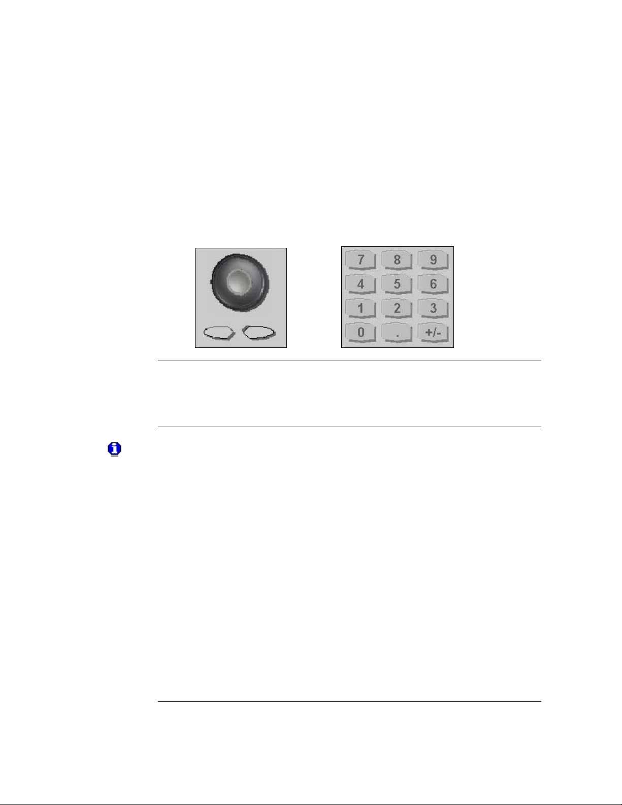
2.4 The Front-Panel Number Entry
81150A and 81160A User’s Guide 27
Page 28
Appendix
Introduction
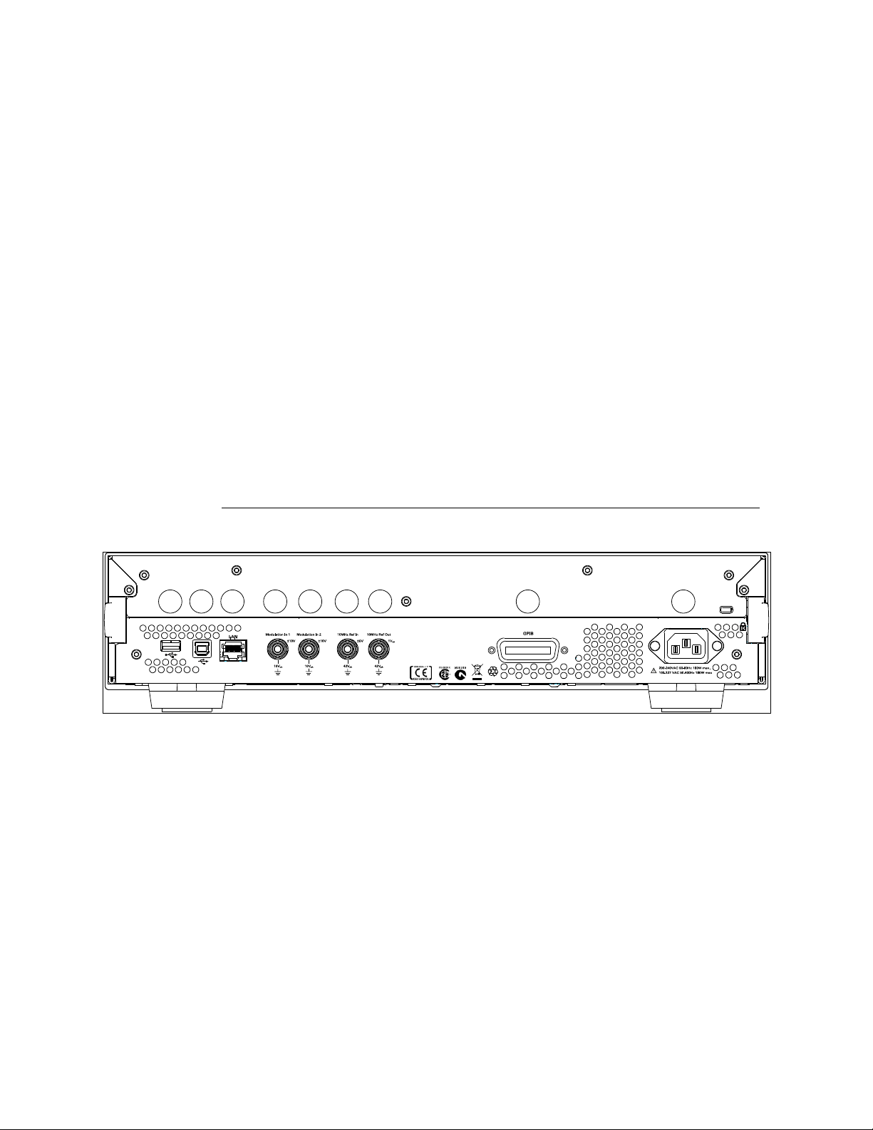
The rear panel contains:
GP-IB connector
USB device connector
LAN connector
These three are used for remote control of the instrument.
Channel 1 Modulation In
Channel 2 Modulation In
10 MHz Clock Ref-In
10 MHz Clock Ref-Out
A USB Host Connector is used to connect external USB storage device for
storing instrument settings or software updates.
4 5 6 7 8 921 3
2.5 The Rear Panel
Rear panel of the 81150A
1 USB Interface Connector (Host type for external mass memory)
2 USB Interface Connector (device type for remote programming)
3 LAN Interface Connector
4 Channel 1 External Modulation Input Terminal
5 Channel 2 External Modulation Input Terminal
6 External 10 MHz Reference Input Terminal
7 10 MHz Reference output Terminal
8 GPIB Interface Connector
9 Power
28
Page 29
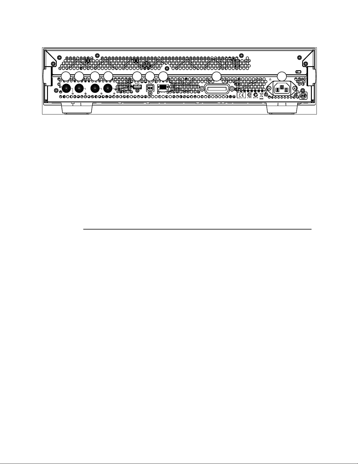
Front-Panel Menu Operation
G PI B
L AN
M o d u l a t i o n I n 1M o d u l a t i o n I n 21 0 M H z Re f I n1 0 M H z Re f O u t
1V
pp
2 0 0 - 2 4 0VAC 5 0 - 6 0 H z 1 8 0 W m a x .
1 0 0 - 1 2 7VAC 5 0 - 4 0 0 H z 1 8 0 W m a x .
10Vpk10V
pk
42V
pk
m a x . 5 V
r m s
± 1 0 V
m a x .
m a x . 5 V
r m s
5 6 71 2 3
4
8 9
Rear panel of the 81160A
1 10 MHz Reference Output Terminal
2 External 10 MHz Reference Input Terminal
3 Channel 1 External Modulation Input Terminal
4 Channel 2 External Modulation Input Terminal
5 USB Interface Connector (Host type for external mass memory)
6 USB Interface Connector (device type for remote programming)
7 LAN Interface Connector
8 GPIB Interface Connector
9 Power
81150A and 81160A User’s Guide 29
Page 30

Appendix
Check the List of
supplied items
Before preparing the 81150A / 81160A for use, check the list of supplied
items, given below:
One Power Cord
USB Cable
Product CD
This User’s Guide (if ordered in printed version)
Getting Started Guide (if ordered in printed version)
Certificate of Calibration
Keysight Automation Ready CD
Connect the Power
Cord and turn on
the 81150A /
81160A
The instrument runs a short power-on self test, which takes about 45-50
seconds. The 81150A / 81160A powers up in the sine wave function at 1
MHz with an amplitude of 1 Vpp (into a 50 termination) or the power-down
setting. At power-on, the Output connector is disabled. To enable the Output
connector, press the output key.
If the 81150A /
81160A does not
turn on….
Steps:
Verify that the power cord is firmly connected to the power
receptacle on the rear panel (the power-line voltage is automatically
sensed at power-on).
You should also make sure that the 81150A / 81160A is connected to
a power source that is energized.
Then, verify that the 81150A / 81160A is turned on.
If the power-on tests fail, the instrument automatically switches to the
diagnostics screen and displays the power on messages.
2.6 Preparing the 81150A / 81160A for Use
30
Page 31

Front-Panel Menu Operation
Introduction
The built-in help system is designed to provide context-sensitive assistance
on any front-panel key or menu softkey. A list of help topics is also available
to assist you with several front-panel operations.
To view the help
information for a
function key
Steps:
Press and hold down the key. If the message contains more
information than will fit on the display, press the up/down keys or
turn the knob to view the remaining information.
Press the Help key to exit Help.
To view the list of
topics
Steps:
Press the Help key to view the list of available help topics.
To scroll through the list, press the up/down arrow keys or rotate the
knob. Select any topic using the Previous Link and Next Link keys,
and press Follow link to obtain details on the selected topic.
Press the Help key to exit Help.
To view the help
information for
displayed
messages
Whenever a limit is exceeded or any other invalid configuration is found, the
81150A / 81160A will display a message. For example, if you enter a value
that exceeds the frequency limit for the selected function, a message will be
displayed. The built-in help system shows all active messages.
Steps:
Press the Help key. Upon doing this, you will see an error or warning
is active (red or yellow text scrolling on the display and a red E or
orange W indicator blinking in the input line). The instrument will
automatically switch to the error or warning screen.
Press the Help key to exit Help.
2.7 Using the Built-in Help System
81150A and 81160A User’s Guide 31
Page 32

Appendix
Introduction
The Mode of operation consists of the following four components:
Coupling between Ch1 & Ch2
Trigger Mode
Waveform Type
Advanced Modes
These are further explained below:
Coupling between
Ch1 & Ch2
There are two output channels available for the Keysight 81150A / 81160A.
The 2 channel version operates in two different modes of operation:
Coupling off: The two channels operate entirely independent. Frequency
generation for both channels is based on the same clock reference.
Coupling on: The frequency, trigger mode, waveform type and advanced
mode are identical for both channels. The delay between the channels is
specified.
Refer to the Appendix for a list of all coupled parameters.
The Trigger Mode, Waveform Type and the Advanced Modes are explained
in the following sections.
2.8 Selecting the Mode of Operation
32
Page 33

Front-Panel Menu Operation
Introduction
The source of a trigger event can be Internal, External, or Manual. The
default is External.
The following trigger modes are explained below:
Continuous
External Triggered
External Gated
Internal Triggered
Manual
The following table explains the functionality of the 81150A / 81160A.
2.9 Selecting Trigger Mode and Source
81150A and 81160A User’s Guide 33
Page 34

Appendix
Trigger Mode
Continuous
Function
Pulse
Square
Sine
Ramp
Noise
Arb
DC
Arming Source
Not Applicable
Advanced Mode
None
Burst
Sweep
Modulation
Trigger Mode
Triggered
Function
Pulse
Square
Sine
Ramp
Noise
Arb
Arming Source
MAN Key
External-In
Internal
Advanced Mode
None
Burst
Sweep
Trigger Mode
Gated
Function
Pulse
Square
Sine
Ramp
Noise
Arb
Arming Source
MAN Key
External-In
Advanced Mode
None
Burst
Sweep
Continuous
Continuous starts the next waveform cycle immediately after the previous
one has finished.
This is used for a continuous waveform, burst, sweep or modulation. The
external input is not used in continuous mode.
34
Page 35

Front-Panel Menu Operation
External Triggered
Triggered generates exactly one ‘signal’ when the trigger condition is met
In the external trigger mode, the 81150A / 81160A will accept a hardware
trigger applied to the front-panel External In connector. The 81150A /
81160A initiates one sweep or outputs one burst each time External In
receives a pulse with the specified edge.
To select the external source, follow these steps:
Press the key on the front panel.
Press Source softkey to select External In as the source. Upon
pressing the Source softkey while the highlight is on the trigger
source, the instrument allows you to choose one of the available
trigger sources. The value can also be changed by turning the Rotary
Knob.
To specify whether the 81150A / 81160A triggers on the rising or falling
edge, follow these steps:
Press the key on the front panel.
Select the desired edge by pressing the Ext-In Sense softkey.
Change the value either by pressing the softkey or by turning the
knob.
External Gated
Gated starts the generation of ‘signals’ as long as the gate is active.
The active level (high or low) at External In enables waveforms, bursts or
sweeps. The last waveform, burst or sweep is always completed.
Internal Triggered
In internal triggered mode, the instrument triggers a single waveform cycle,
sweep or burst at an adjustable trigger rate.
E.g. generate a pulse every 250ms
This mode is enabled by pressing the key on the front panel and
then setting source to Internal. As soon as Source is set to Internal, the
trigger frequency/period can be adjusted by navigating to Int Freq or Int.
Period (depends on which of the two is currently active). Switching between
Int Freq and Int Period is done by navigating to the internal trigger
frequency/period and then pressing the corresponding softkey.
81150A and 81160A User’s Guide 35
Page 36

Appendix
Manual
In the manual trigger mode, you can manually trigger the 81150A / 81160A
by pressing the front panel key. The 81150A / 81160A initiates one
waveform cycle, sweep or outputs one burst for each time you press or
release the key. The key is illuminated while the 81150A / 81160A is
waiting for a manual trigger.
Front Panel
Operation
To set the Trigger Mode, do the following:
Press the corresponding key on the Front-Panel.
For selecting the arming source, press the Front panel key for the
desired trigger mode, press the Source softkey or navigate to Source
using the navigation keys.
Then change the selection.
36
Page 37

Front-Panel Menu Operation
Introduction
The 81150A / 81160A can output six standard waveforms including:
Pulse
Sine
Square
Ramp
Noise
Arbitrary
You can also select one of the seven built-in arbitrary waveforms or create
your own custom waveforms.
You can internally modulate any of the standard waveforms (except pulse
and noise and DC) and also arbitrary waveforms using AM, FM, PM or FSK.
Pulse Waveform
Characteristics
A pulse is defined by the following parameters:
Amplitude/Offset or High-Level/Low-Level
Period or Frequency (not applicable for triggered pulses)
Width in seconds or Duty Cycle or Trailing delay in seconds
Delay in seconds
Delay as percentage of the period (not applicable for triggered
pulses)
Delay as phase in degree (not applicable for triggered pulses)
Leading edge transition time in seconds
Leading edge transition time in percent of width
Trailing edge transition time in seconds
Trailing edge transition time in percent of width
Polarity
Source Impedance
Load Impedance
2.10 Selecting the Waveform
81150A and 81160A User’s Guide 37
Page 38

Appendix
Pattern
Characteristics
Patterns are defined by the following parameters:
Internal or external pattern source
PRBS patterns and user defined patterns
NRZ formatting and Arbitrary Bit Waveform
Pattern Mode - On/Off
Patterns are also characterized by 2, 3 or 4 different levels per bit
Adjustable loop offset, allowing emulation of initialization preamble
and looped test pattern
External pattern source allows re-timing and re-shaping of externally
provided data stream
Sine Wave
Characteristics
A sine wave is defined by the following parameters:
Amplitude/Offset or High/Low Level
Period or Frequency
Delay in seconds
Delay in percent of period
Delay as phase in degree
Polarity
Source Impedance
Load Impedance
Square Wave
Characteristics
A square wave is defined by the following parameters:
Amplitude/Offset or High-Level/Low-Level
Period or Frequency
Duty Cycle
Delay in seconds
Delay as percentage of the period
Delay as phase in degree
Polarity
Source Impedance
Load Impedance
The instrument will always generate the fastest possible transition times
when generating square waves.
38
Page 39

Front-Panel Menu Operation
Ramp Wave
Characteristics
A ramp is defined by the following parameters:
Amplitude/Offset or High/Low Level
Period or Frequency
Delay in seconds
Delay in percent of period
Delay as phase in degree
Symmetry point in percent of period.
Polarity
Source Impedance
Load Impedance
Noise Wave
Characteristics
Noise is defined by the following parameters:
Amplitude/Offset or High/Low Level
Probability Density Function (PDF)
Source Impedance
Load Impedance
Arbitrary Wave
Characteristics
Arbitrary waveforms are defined by the following parameters:
Amplitude/Offset or High/Low Level
Period or Frequency
Delay in seconds
Delay in percent of period
Delay as phase in degree
Source Impedance
Load Impedance
81150A: Arbitrary waveforms can have up to 512k samples. The local
waveform editor allows to create and edit waveforms with up to 16k
samples.
81160A: Arbitrary waveforms can have up to 256k samples (1 channel) /
128k samples (2 channels). The local waveform editor allows to create and
edit waveforms with up to 16k samples.
81150A and 81160A User’s Guide 39
Page 40

Appendix
Introduction
There are three advanced modes of operation available:
Modulation
Burst
Sweep
These advanced modes are further explained below.
Introduction
The following types of modulation are available:
AM
FM
PM
FSK
PWM
To select
Modulation
Refer to Chapter 3, Features and Functions to understand how to select any
of these modulations.
The 81150A / 81160A will allow only one modulation mode to be
enabled at a time. For example, you cannot enable AM and FM at the
same time. When you enable AM, the previous modulation mode is
turned off.
The 81150A / 81160A will not allow any advanced mode to be
enabled with another advanced mode on the same channel.
2.11 Selecting the Advanced Mode
2.11.1 Modulation
40
Page 41

Front-Panel Menu Operation
Introduction
You can configure the 81150A / 81160A to output a waveform with a
specified number of pulses/waveform cycles, called a burst. You can output
the burst at a rate determined by the internal rate generator or the signal
level on the Front Panel External In connector.
A burst can be initiated either by:
An Internal Immediate event, which triggers a continuous burst.
A trigger source, which triggers a triggered burst.
An active gate, which enables a gated burst.
Select the function
and amplitude for
the burst
For burst waveforms, you can select sine, square, ramp, pulse, or arbitrary
waveforms.
Burst mode cannot be used when using DC or noise.
Select the burst
mode
Press and specify the #Cycles and the Start Phase softkeys
to set the desired values.
The Start Phase defines the phase at which signal generation starts.
The allowed range is -360 to +360. It is only applicable to Sine and
Arb waveforms.
Refer to Outputting a Burst Waveform for details.
2.11.2 Burst
81150A and 81160A User’s Guide 41
Page 42

Appendix
Introduction
In the frequency sweep mode, the 81150A / 81160A “steps” from the start
frequency to the stop frequency at a sweep rate which you specify.
The 81150A / 81160A can produce a frequency sweep for sine, square,
ramp, or arbitrary waveforms (pulse, noise, and dc are not allowed).
To select a Sweep
Press to output a sweep using the present settings for frequency,
output amplitude, and offset. Enable sweep before setting up any of the
other sweep parameters.
The 81150A / 81160A will not allow the sweep mode to be enabled at the
same time when burst or any modulation mode is enabled. When you enable
sweep, the burst or modulation mode is turned off.
2.11.3 Sweep
42
Page 43

Front-Panel Menu Operation
Introduction
At power-on, normally, the instrument outputs the same setting as before
power-down. The default frequency is 1 MHz and the default amplitude is 1
Vpp.
When you change functions, the same frequency is used if the present value
is valid for the new function.
The following steps show you how to change the frequency.
Press the
“Frequency”
softkey
To set the waveform frequency, press the Frequency softkey. Pressing the
frequency softkey when Frequency is already selected, will toggle to Period.
The current selection is highlighted as shown in the image below.
Enter the
magnitude of the
desired frequency
Using the numeric keypad, enter the desired value, say 1.2
2.12 Setting the Output Frequency
81150A and 81160A User’s Guide 43
Page 44

Appendix
Select the desired
units
Select and press the softkey that corresponds to the desired units. Press the
More softkey to view more units available for the current selection. When
you select the units, the 81150A / 81160A outputs a waveform with the
displayed frequency (if the output is enabled).
You can also enter the desired value using the knob and cursor keys.
You can also change the exponent by setting the input cursor to the
exponent field and turning the Rotary Knob. To do this, use the
left/right key to place the cursor on the exponent you wish to
change.
44
Page 45

Front-Panel Menu Operation
Introduction
At power-on, normally, the instrument outputs the same setting as before
power-down.
When you change functions, the same amplitude is used if the present value
is valid for the new function.
The following steps show you how to change the amplitude:
Press the “Ampl”
softkey
To set the amplitude using a high level and low level, press the Ampl
softkey.
This will offer the level representations and units that can be chosen
for the output levels.
Choose the appropriate option from the given choices.
Press More to go to the units screen. Choose from the given units, by
pressing that unit itself.
2.13 Setting the Output Amplitude
81150A and 81160A User’s Guide 45
Page 46

Appendix
Enter the
magnitude of the
desired amplitude
Using the numeric keypad, enter the desired value.
Select the desired
units
Select and press the softkey that corresponds to the desired units. When
you select the units, the 81150A / 81160A outputs a waveform with the
displayed amplitude (if the output is enabled). For this example, press mVrms.
46
Page 47

Front-Panel Menu Operation
Introduction
You can easily convert the displayed amplitude from one unit to another.
For example, the following steps show you how to convert the amplitude
from Vrms to Vpp.
Enter the numeric
entry mode
To switch between different representations, press the amplitude, offset,
high level, low level softkey and then choose the different representation.
You can choose between High/Low, Ampl/Offs.
Select the new
units
Steps:
Press Ampl softkey and then press the MORE softkey.
This brings you to another menu layer where you can choose
between Vpp/Vdc, Vrms/Vdc, dBm/Vdc that will be used when
Ampl/Offs is selected. The same softkey menu provides easy
application of TTL and ECL level settings.
2.13.1 Converting the amplitude from one unit to another
81150A and 81160A User’s Guide 47
Page 48

Appendix
Introduction
The time between the start of a period until the start of the waveform is
called the delay. The start of a period is defined when the delay is set to 0ns.
It can be measured between the Trigger Out and Out Connector.
Delay Format
Delay has the following format:
Abs. Delay
% of Period
Phase
To select Delay
Steps:
Press the Delay softkey.
This will show the available choices for the delay format.
2.14 Selecting Delay
48
Page 49

Front-Panel Menu Operation
Abs. Delay
Defines the time between the start of a period until the start of the
waveform in units of seconds.
% of Per
Defines the time between the start of a period till the start of the waveform
as a percentage of the period.
Phase
Defines the time between the start of a period till the start of the waveform
in degrees (1/360 of the period).
Selecting any of the delay formats will take you back to the main screen.
81150A and 81160A User’s Guide 49
Page 50

Appendix
Introduction
You can select the "DC Volts" feature from the “Utility” menu, and then set
a constant dc voltage as an "Offset" value. As an example, let us set "DC
Volts" = -1.5 Vdc.
To select DC Volts
Steps:
Press and then press the DC Mode softkey.
Press the DC softkey to toggle between DC mode off and on. When
DC mode is being turned off, then the instrument will switch back to
the parameter screen of the waveform being generated.
2.15 Selecting DC Volts
50
Page 51

Front-Panel Menu Operation
Introduction
At power-on, normally, the instrument outputs the same setting as before
power-down.
The following steps show you how to change the offset.
Press the “Offset”
softkey
Steps:
Press the Offset softkey to select the DC offset voltage. Enter the
desired voltage level as an “Offset” (as shown in the image below)
When you change functions, the same offset is used if the present value is
valid for the new function.
Enter the
magnitude of the
desired offset
Using the numeric keypad, enter the value “-1.5” (as shown in the image
below).
2.16 Setting a DC Offset Voltage
81150A and 81160A User’s Guide 51
Page 52

Appendix
Select the desired
units
Select and press the softkey that corresponds to the desired units. You can
choose from mVdc or Vdc. When you select the units, the 81150A / 81160A
outputs the waveform with the displayed offset (if the output is enabled).
For this example, press Vdc.
52
Page 53

Front-Panel Menu Operation
Introduction
At power-on, normally, the instrument outputs the same setting as before
power-down.
The duty cycle is limited by the minimum pulse width of Wmin.
This means the duty cycle can get as low as (100% * Wmin/period) and as
high as (100% * (1 –Wmin/period))
81150A: Where Wmin is either 4.1ns or 10ns depending on the selected
amplifier (See section Amplifier Type Selection).
81160A: Where Wmin is 1.5ns.
The following steps show you how to change the duty cycle to 30%.
Select the square
wave function
Press the key and then set the desired output frequency to any value
up to 120 MHz for the 81150A (330 MHz for the 81160A).
Press the “Duty
Cycle” softkey
The duty cycle represents the amount of time per cycle that the square
wave is at a high level.
Enter the desired
duty cycle
Using the numeric keypad or the knob, select a duty cycle value of “30”. The
81150A / 81160A adjusts the duty cycle immediately and outputs a square
wave with the specified value (if the output is enabled).
2.17 Setting the Duty Cycle of a Square Wave
81150A and 81160A User’s Guide 53
Page 54

Appendix
Introduction
You can specify a signal by setting its amplitude and dc offset values.
Another way to set the limits of a signal is to specify its high-level
(maximum) and low-level (minimum) values. This is typically convenient for
digital applications.
In the following example, let us set the high-level to 1.0 V and the low-level
to 0.0 V.
To Set the HighLevel and LowLevel Values
Steps:
Press the Ampl softkey to select Ampl.
Press the softkey again to toggle to show the different
representations of the output voltages.
Press the High Low softkey to select High level and Low level
Both the Ampl and Offset softkeys toggle together, to High and Low,
respectively.
Set the High Level value using the numeric keypad or the knob.
Press the Low Level softkey and set the value using the numeric
keypad or the knob.
These settings (high-level = "1.0 V" and low-level = "0.0 V") are equivalent
to setting an amplitude of "1.0 Vpp" and an offset of "500 mVdc".
2.18 Setting the High-Level and Low-Level Values
54
Page 55

Front-Panel Menu Operation
Introduction
You can configure the 81150A / 81160A to output a pulse waveform with
variable pulse width and edge time.
The following steps show you how to configure a 500 ms pulse waveform
with a pulse width of 10 ms and edge times of 50 ns.
Pulses do not have period/frequency when being triggered and burst is off.
In all other cases, a pulse does have a period/frequency like other
waveforms.
Select the pulse
function
Press the key to select the pulse function and output a pulse
waveform with the default parameters. This is only true if the instrument is
currently using the default setting.
Set the pulse
period
Press the Frequency softkey to toggle to Period. Set the Pulse period to 500
ms.
2.19 Configuring a Pulse Waveform
81150A and 81160A User’s Guide 55
Page 56

Appendix
Set the pulse width
Press the Width softkey and then set the pulse width to 10 ms. The pulse
width represents the start of leading edge to start of trailing edge.
Set the edge time
for both edges
Press the Lead Edge and Trail Edge softkeys and then set the edge time for
both the rising and falling edges to 50 ns. The edge time represents the time
from the 10% threshold to the 90% threshold of each edge.
56
Page 57

Front-Panel Menu Operation
Introduction
The pattern functionality can be accessed on the local user interface
through the Pattern Setup key on the pulse screen.
Press the “Pattern
Setup” key
Press the key to select the Pulse function.
Press the Pattern Setup softkey shown in the image below.
This will show the Pattern Setup screen as shown in the following
image.
2.20 Setting up a Pattern
81150A and 81160A User’s Guide 57
Page 58

Appendix
Pattern Mode
Press the Select Pattern softkey to select from the available built-in
PRBS patterns or user defined patterns.
Use the Rotary Knob or up/down Arrow keys to select.
58
Page 59

Front-Panel Menu Operation
Introduction
In the Graph Mode, you can view a graphical representation of the current
waveform parameters. The softkeys are listed in the same order as in the
normal display mode, and they perform the same function.
However, only one label, Frequency or Period is displayed for each softkey
at one time.
Enable the Graph
Mode
Press the key to enable the Graph Mode.
Select the desired
parameter
To select a specific parameter, note the softkey labels at the bottom of the
display. For example, to select delay, press the Delay softkey.
As in the normal display mode, you can edit numbers using either the
numeric keypad or the knob and cursor keys.
The parameter which is selected using the softkey highlights the
same value in the graph diagram also. For e.g., if you select Period,
then the value of Period will be highlighted in the graph.
To exit the Graph Mode, press again.
The key also serves as a Local key to restore front-panel control
after remote interface operations.
2.21 Viewing a Waveform Graph
81150A and 81160A User’s Guide 59
Page 60

Appendix
Introduction
There are seven built-in arbitrary waveforms stored in the non-volatile
memory.
The following steps show you how to output the built-in “exponential fall”
waveform from the front panel.
Select the arbitrary
waveform function
When you press the key to select the arbitrary waveform function,
the 81150A / 81160A displays the currently used waveform in the textual
screens indicating which waveform is currently selected (the default is
“exponential rise”).
Select the active
waveform
Steps:
Press the MORE softkey twice.
This brings you to a screen which has Select Waveform softkey on
it.
Press the Select Waveform softkey and select from the given
options. Choose the desired waveform and press select. Confirm your
choice by pressing Yes.
The 81150A / 81160A has a graphical browser to select the waveform to be
used. This waveform can either be a predefined one, or a user defined one
(from VOLATILE memory or a stored waveform from NON-VOLATILE
memory). It is also possible to import a waveform from a USB stick into
VOLATILE memory.
2.22 Outputting a Stored Arbitrary Waveform
60
Page 61

Front-Panel Menu Operation
For information on creating a custom arbitrary waveform, refer to Creating
and Storing an Arbitrary Waveform.
81150A and 81160A User’s Guide 61
Page 62

Appendix
Introduction
The Keysight 81150A has a selectable series output impedance of either
50 ohms or 5 ohms to the front-panel output connector. If the actual load
impedance is different than the value specified, the displayed amplitude and
offset levels will be incorrect. The load impedance setting is simply provided
as a convenience to ensure that the displayed voltage matches the expected
load.
The Keysight 81160A has a fixed series output impedance of 50 ohms to the
front-panel output connector.
Press any
waveform screen
Press any of the waveform screens, i.e. Pulse, Sine, Square, Ramp, Noise or
Arb to adjust the output and load impedance.
Navigate the menu
to set the output
termination
Press the Load Impedance and Out Impedance softkeys to set the desired
values.
2.23 Selecting the Output Termination
62
Page 63

Front-Panel Menu Operation
Select the output
amplifier type and
ranging
Press the key and then select the Output Setup softkey.
Select Amplifier
Type and Range
For Amplifier Type, choose from max Amplitude or max Bandwidth.
For Amplifier Range, choose from Hold, Auto or Auto Once.
Refer to the Amplifier Type Selection section for more information.
The Amplifier Type selection is available for the 81150A, only.
81150A and 81160A User’s Guide 63
Page 64

Appendix
Introduction
A modulated waveform consists of a carrier and a modulating waveform. In
AM (amplitude modulation), the amplitude of the carrier is varied by the
amplitude of the modulating waveform.
For this example, you will output an AM waveform with 80% modulation
depth. The carrier will be a 5 kHz sine wave and the modulating waveform
will be a 200 Hz sine wave.
Select the function,
frequency, and
amplitude of the
carrier
Press and then press the Frequency, Ampl, and Offset softkeys to
configure the carrier waveform. For this example, select a 5 kHz sine wave
with an amplitude of 5 Vpp.
Select AM
Press and then select “AM” using the Type softkey. Notice that a
status message “AM by Sine” is shown in the status line. The status line is
located between the parameters section of the screen and the input field.
2.24 Outputting a Modulated Waveform
64
Page 65

Front-Panel Menu Operation
Set the modulation
depth
Press the AM Depth softkey and then set the value to 80% using the
numeric keypad or the knob and cursor keys.
Set the modulating
frequency
Press the AM Frequency softkey and then set the value to 200 Hz using the
numeric keypad or the knob and cursor keys.
Select the
modulating
waveform shape
Press More and then press the AM Shape softkey to select the shape of the
modulating waveform. For this example, select a sine wave.
At this point, the 81150A / 81160A outputs an AM waveform with the
specified modulation parameters (if the output is enabled).
81150A and 81160A User’s Guide 65
Page 66

Appendix
View the waveform
Press to view the waveform parameters.
To turn off the Graph Mode, press again.
66
Page 67

Front-Panel Menu Operation
Introduction
You can configure the 81150A / 81160A to “shift” its output frequency
between two preset values using FSK modulation. The rate at which the
output shifts between the two frequencies (called the “carrier frequency”
and the “hop frequency”) is determined by the internal rate generator or the
signal level on the rear-panel Modulation In connector. (There is one
Modulation In connector for each channel.)
For this example, you will set the “carrier” frequency to 3 kHz and the “hop”
frequency to 500 Hz, with an FSK rate of 100 Hz.
Select the function,
frequency, and
amplitude of the
carrier
Press and then press the Frequency, Ampl, and Offset softkeys to
configure the carrier waveform.
For this example, select a 3 kHz sine wave with an amplitude of 5 Vpp.
Select FSK
Press and then select FSK using the Modulation Type softkey.
Notice that a status message FSK, Internal is shown in the status line. This
message is applicable for all waveforms.
2.25 Outputting an FSK Waveform
81150A and 81160A User’s Guide 67
Page 68

Appendix
Set the “hop”
frequency
Press the Hop Freq softkey and then set the value to 500 Hz using the
numeric keypad or the knob and arrow keys.
Set the FSK “shift”
rate
Press the FSK Rate softkey and then set the value to 100 Hz using the
numeric keypad or the knob and arrow keys.
At this point, the 81150A / 81160A outputs an FSK waveform (if the output
is enabled).
68
Page 69

Front-Panel Menu Operation
View the waveform
Press to view the waveform parameters.
To turn off the Graph Mode, press again.
81150A and 81160A User’s Guide 69
Page 70

Appendix
Introduction
You can configure the 81150A / 81160A to output a pulse width modulated
(PWM) waveform. The Keysight 81150A / 81160A provides PWM for pulse
carrier waveforms, and PWM is the only type of modulation supported for
pulse waveforms. In PWM, the pulse width or duty cycle of the carrier
waveform is varied according to the modulating waveform. You can specify
either a pulse width and width deviation, or a pulse duty cycle and duty
cycle deviation, the deviation to be controlled by the modulating waveform.
For this example, you will specify a pulse width and pulse width deviation
for a 1 kHz pulse waveform with a 100 Hz sine wave modulating waveform.
Select the carrier
waveform
parameters
Press and then press the Frequency, Delay, Ampl, Offset, Width,
and Lead Edge and Trail Edge softkeys to configure the carrier waveform.
For this example, select a 1 kHz pulse waveform with an amplitude of 1 Vpp,
a 0 V offset, a pulse width of 500 s, and a lead edge of 70 ns and trail edge
of 20 ns.
Select PWM
Press (PWM is the only modulation type for Pulse).
Notice that a status message "PWM by Sine" is shown in the status line.
2.26 Outputting a PWM Waveform
70
Page 71

Front-Panel Menu Operation
Set the width
deviation
Press the Width Deviation softkey and set the value to 400 µs using the
numeric keypad or the knob and cursor keys.
Set the modulating
frequency
Press the PWM Frequency softkey and then set the value to 5 Hz using the
numeric keypad or the knob and cursor keys.
Select the
modulating
waveform shape
Press the PWM Shape softkey to select the shape of the modulating
waveform. For this example, select a sine wave.
At this point, the 81150A / 81160A outputs a PWM waveform with the
specified modulation parameters (if the output is enabled).
View the waveform
Press to view the waveform and parameters.
To turn off the Graph Mode, press again.
To really view the PWM waveform, you would need to output it to an
oscilloscope. If you do this, you will see how the pulse width varies, in this
case, from 100 to 900 µs. At a modulation frequency of 5 Hz, the deviation is
quite visible.
81150A and 81160A User’s Guide 71
Page 72

Appendix
Introduction
In the frequency sweep mode, the 81150A / 81160A “steps” from the start
frequency to the stop frequency at a sweep rate which you specify. You can
sweep up or down in frequency, and with either linear or logarithmic
spacing.
For this example, you will output a swept sine wave from 50 Hz to 5 kHz.
You will not change the other parameters from their default settings:
internal sweep trigger, linear spacing, and 1 second sweep time.
Select the function
and amplitude for
the sweep
For sweeps, you can select sine, square, ramp, or arbitrary waveforms
(pulse, noise, and dc are not allowed). For this example, select a sine wave
with an amplitude of 5 Vpp.
Select the sweep
mode
Press and then verify that the linear sweep mode is currently
selected. Notice that a status message “Linear Sweep” is shown in the
status line.
2.27 Outputting a Frequency Sweep
72
Page 73

Front-Panel Menu Operation
Set the start
frequency
Press the Start Frequency softkey and then set the value to 50 Hz using the
numeric keypad or the knob and cursor keys.
Set the stop
frequency
Press the Stop Frequency softkey and then set the value to 5 kHz using the
numeric keypad or the knob and cursor keys.
At this point, the 81150A / 81160A outputs a continuous sweep from 50 Hz
to 5 kHz (if the output is enabled).
81150A and 81160A User’s Guide 73
Page 74

Appendix
If desired, you can set the frequency boundaries of the sweep using a center
frequency and frequency span. These parameters are similar to the start
frequency and stop frequency and are included to give you added flexibility.
To achieve the same results, set the center frequency to 2.525 kHz and the
frequency span to 4.950 kHz.
View the waveform
Press to view the waveform parameters.
To turn off the Graph Mode, press again.
You can generate a single frequency sweep by pressing the
key, but only if triggered mode is active.
The 81150A / 81160A can also have gated sweeps. In this case it will
start a new sweep as long as the gate is active. If the gate is getting
inactive while a sweep is generated, this sweep will be finished. For
more information, see “Triggering a Sweep or Burst”.
74
Page 75

Front-Panel Menu Operation
Introduction
You can configure the 81150A / 81160A to output a waveform with a
specified number of cycles, called a burst. You can output the burst at a rate
determined by the internal rate generator or the signal level on the Front
Panel External In.
For this example, you will output a three-cycle sine wave with a 20 ms burst
period. You will not change the other parameters from their default settings:
internal burst source and 0 degree starting phase.
Select the burst
mode
Press to enable or disable burst mode. Notice that a status message
Burst is shown in the status line.
Set the burst count
Press the #Cycles softkey and then set the count to “3” using the numeric
keypad or knob.
2.28 Outputting a Burst Waveform
81150A and 81160A User’s Guide 75
Page 76

Appendix
Start Phase
Defines the start phase of the waveform that is bursted. The start phase is
only available for sinewave, and arb waveforms. Noise and DC do not have a
period and thus no phase information. Square, ramp and pulse is generated
in a way that does not allow the use of a start phase.
The Start Phase can vary between -360 to 360.
Set the
period/frequency
Steps:
Set the period/frequency of the sinewave to 2 ms.
Enable triggered mode.
Select Internal trigger source.
Set the internal frequency to 50 Hz or the internal period to 20 ms.
76
Page 77

Front-Panel Menu Operation
View the waveform
Press to view the waveform parameters.
To turn off the Graph Mode, press again.
You can generate a single burst (with the specified count) by pressing the
key. For more information, see “Triggering a Sweep or Burst”.
You can also use an external gate signal to either turn the burst signal “on”
or “off” based on the external signal applied to the Front panel External In
connector. For more information, see Burst Mode.
81150A and 81160A User’s Guide 77
Page 78

Appendix
Introduction
There are 3 different trigger/gate sources:
External (this is default)
Internal (this is the programmable timebase)
Manual (this is the key on the front panel or the *TRG command on
the remote interface).
You can issue triggers from the front panel for sweeps and bursts using a
manual trigger or an internal trigger.
Internal or
“automatic
triggering”
Internal or “automatic” triggering is enabled with the default settings of the
81150A / 81160A. In this mode, the 81150A / 81160A outputs continuously
when the sweep or burst mode is selected.
When using the “automatic” triggering, the ‘Cont’ key is illuminated on the
Front Panel.
Gated Sweep or
Burst
Bursts or sweeps are enabled by (Gated by) an active level at the selected
arming source:
External Input (External Signal) gated while high or low or both.
Man key on Front Panel, gated while pressed or released or both.
Triggered Sweep or
Burst
A burst or a sweep is triggered by an active edge at the selected arming
source.
Internal, select the triggering period.
External Input (External Signal) triggered by rising or falling or both
edges.
Man key on Front Panel, triggered by press or release or both.
2.29 Triggering a Sweep or Burst
78
Page 79

Front-Panel Menu Operation
Introduction
You can store the instrument state in one of four non-volatile storage
locations. A fifth storage location automatically holds the power-down
configuration of the instrument. When power is restored, the instrument can
automatically return to its state before power-down.
Select the desired
storage location
Press and then select the Store State softkey.
2.30 Storing the Instrument State
81150A and 81160A User’s Guide 79
Page 80

Appendix
Select a custom
name for the
selected location
If desired, you can assign a custom name to each of the four locations.
The name can contain up to 12 characters. The first character must
be a letter but the remaining characters can be letters, numbers, or
the underscore character (“_”), and “.”.
To add additional characters, keep pressing the right-cursor key
unless it reaches the place where you want to insert a character.
Then, turn the knob to obtain the desired character.
To delete all characters to the right of the cursor position, press
.
To use numbers and “.” in the name, you can enter them directly
from the numeric keypad.
Store the
instrument state
Press the STORE STATE softkey. The softkeys for each of these states, i.e.,
state 1 to 4 has two meanings:
Select the state to store to.
When being selected, the text on the softkey changes to ‘STORE
STATE x’, where x is 1, 2, 3 or 4. Pressing this softkey actually
performs the ‘store operation’. This will be confirmed with a scrolling
text in the status line (Stored instrument state to location x).
The instrument stores the selected function, frequency, amplitude, dc offset,
duty cycle, symmetry, as well as any modulation parameters in use. The
instrument does not store volatile waveforms created in the arbitrary
waveform function.
80
Page 81

Front-Panel Menu Operation
If you delete an arbitrary waveform from non-volatile memory after storing
the instrument state, the waveform data is lost and the instrument will not
output the waveform when the state is recalled. The built-in “exponential
rise” waveform is output in place of the deleted waveform.
When power is turned off, the instrument automatically stores its powerdown state. You can configure the instrument to automatically recall the
power-down state when power is restored.
81150A and 81160A User’s Guide 81
Page 82

Appendix
Introduction
This section gives information on configuring the 81150A / 81160A for
remote interface communication. For information on the SCPI commands
available to program the 81150A / 81160A over the remote interface, refer to
chapter 4.
The Keysight 81150A / 81160A supports remote interface communication
using a choice of three interfaces: GPIB, USB, and LAN, explained below. All
three interfaces are "live" at power up. The instructions that follow explain
how to configure your remote interface from the instrument front panel.
The CD-ROM provided with your instrument contains connectivity software
to enable communications over these interfaces. Refer to the instructions
provided on the CD-ROM to install this software on your PC.
Introduction
Each device on the GPIB interface must have a unique address. The address
is stored in the non-volatile memory and does not change when power has
been off or after a remote interface reset.
Follow these steps to set the GPIB address:
Select the “I/O”
menu
Press and then press the I/O Interfaces softkey.
2.31 Configuring the Remote Interface
2.31.1 GPIB Configuration
82
Page 83

Front-Panel Menu Operation
Select the GPIB
address
Use the knob and cursor keys or the numeric keypad to select a GPIB
address in the range 0 through 31 (the factory default is “10”). The GPIB
address is shown on the front-panel display at power-on.
Exit the menu
Press the Enter softkey to enter the GPIB address and exit.
Your computer’s GPIB interface card has its own address. Be sure to avoid
using the computer’s address for any instrument on the interface bus.
Introduction
The USB interface requires no front panel configuration parameters. Just
connect your Keysight 81150A / 81160A to your PC using a standard USB
cable and the interface will self configure.
2.31.2 USB Configuration
81150A and 81160A User’s Guide 83
Page 84

Appendix
Introduction
There are several parameters that you may need to set to establish network
communication using the LAN interface. Primarily, you will need to establish
an IP address. You may need to contact your network administrator for help
in establishing communication with the LAN interface.
Follow these steps to set the LAN address:
Select the “I/O”
Interfaces menu
Press and then press the I/O Interfaces softkey.
Select the “LAN”
menu
Press the LAN softkey.
From this menu, you can select IP Setup to set an IP address and related
parameters, DNS Setup to configure DNS.
The Current Config is always displayed on the LAN screen.
LAN RESET does reset the LAN configuration back to DHCP/Auto-IP
and enables the web server.
2.31.3 LAN Configuration
84
Page 85

Front-Panel Menu Operation
Establish an “IP
Setup”
To use the Keysight 81150A / 81160A on the network, you must first
establish an IP setup, including an IP address, and possibly a subnet mask
and gateway address. Press the IP Setup softkey. By default, DHCP/Auto-IP
(Dynamic Host Configuration Protocol) is set to On.
With DHCP/AutoIP On, IP address
will automatically
be set
With DHCP/Auto-IP On, an IP address will automatically be set by
DHCP/Auto-IP when you connect the Keysight 81150A / 81160A to the
network, provided the DHCP server is found and is able to do so. DHCP also
automatically deals with the subnet mask and gateway address, if required.
This is typically the easiest way to establish LAN communication for your
instrument. All you need to do is leave DHCP/Auto-IP On.
However, if you cannot establish communication by means of DHCP/AutoIP, you will need to manually set an IP address, and a subnet mask and
gateway address if they are in use.
To establish an IP setup, follow these steps:
Set the “IP
Address”
Press the softkey to select DHCP/Auto-IP Off. The manual selection
softkeys appear and the current IP address is displayed.
Contact your network administrator for the IP address to use. All IP
addresses take the form "nnn.nnn.nnn.nnn" where each "nnn" is a byte
value in the range 000 through 255. You can enter a new IP address using
the numeric keypad (not the knob). Just type in the numbers and the period
delimiters using the keypad. Use the left cursor key as a backspace key.
81150A and 81160A User’s Guide 85
Page 86

Appendix
Set the “Subnet
Mask”
The subnet mask is required if your network has been divided into subnets.
Ask your network administrator whether a subnet mask is needed, and for
the correct mask. Press the Subnet Mask softkey and enter the subnet
mask in the IP address format (using the keypad).
Set the “Default
Gateway”
The gateway address is the address of a gateway, which is a device that
connects two networks. Ask your network administrator whether a gateway
is in use and for the correct address. Press the Default Gateway softkey and
enter the gateway address in the IP address format (using the keypad).
Exit the “IP Setup”
menu
Press Back to return to the "LAN" menu.
86
Page 87

Front-Panel Menu Operation
Configure the “DNS
Setup” (optional)
DNS (Domain Name Service) is an Internet service that translates domain
names into IP addresses. Ask your network administrator whether DNS is in
use, and if it is, ask for the host name and DNS server address to use.
Steps:
Start at the “LAN” menu.
Press the DNS Setup softkey to display the “Host Name” field.
Set the “Host
Name”
Steps:
Press the Host Name softkey and enter the host name. The host
name is the host portion of the domain name, which is translated
into an IP address. The host name is entered as a string using the
knob and cursor keys to select and change characters. The host
name may include letters, numbers, and dashes (“-”). You can use
the keypad for the numeric characters only.
Press to delete all characters to the right of the cursor
position.
Set the “Domain
Name”
The Domain Name cannot be changed. But, the name that was detected by
the Operating System is displayed for information.
81150A and 81160A User’s Guide 87
Page 88

Appendix
Set the “DNS
Server” address
Press the DNS Server softkey and enter the address of the DNS server
(there are two DNS Server addresses) in the IP address format (using the
keypad).
Set the “WINS
Server” address
Press the WINS Server softkey and enter the address of the WINS server
(there are two WINS Server addresses) in the IP address format (using the
keypad).
Exit the “DNS
Setup” menu
Press the Back softkey to return to the previous screen. This will bring you
back to the LAN menu.
Exit the menu
Press the key to directly enter from the LAN menu. Else, keep
pressing the Back key unless you reach the required screen.
88
Page 89

Front-Panel Menu Operation
Introduction
To reset the instrument to its factory default state, press and then
select the Set to Defaults softkey. Press YES to confirm the operation.
The Set to Defaults functionality will program the instrument’s default
setting. This is related to the electrical signals that are generated at the
instruments output connectors.
The Set to Defaults does not affect system settings like GPIB address, LAN
configuration, and Display brightness. In short everything that has nothing to
do with the BNC connectors.
There is another mechanism that will reset everything. This is called
SECURE ALL and can be found under Utility/System/Security.
SECURE ALL does a full format of every NON-VOLATILE storage in the
instrument:
Set the instrument’s default setting (just like ‘Set to Defaults’)
It erases all settings and waveforms that are stored on the
instruments internal memory
It resets all system settings like LAN, GPIB address.
SECURE ALL brings the instrument back to the ‘delivery state’, and takes
some time (several minutes) in doing this.
For a complete listing of the instrument’s power-on ans reset conditions,
see “Factory Default Settings”.
2.32 Resetting the 81150A / 81160A
81150A and 81160A User’s Guide 89
Page 90

Appendix
Introduction
This section makes it easy to look up all the details about a particular
feature of the 81150A / 81160A. Whether you are operating the 81150A /
81160A from the front panel or over the remote interface, this chapter will
be useful.
What’s inside this
Chapter
This section contains the following sections:
Trigger Mode
Output Configuration
Input Configuration
Pulse Waveforms
Pattern Capabilities
Noise
Amplitude Modulation (AM)
Frequency Modulation (FM)
Phase Modulation (PM)
Frequency-Shift Keying (FSK) Modulation
Pulse Width Modulation (PWM)
Frequency Sweep
Burst Mode
Arbitrary Waveforms
Creating and Storing an Arbitrary Waveform
Managing Stored Waveforms
Additional Information on Arbitrary Waveforms
System-Related Operations
Remote Interface Configuration
Software Update
Installing Licenses
Diagnostics/Calibration Overview
Security
Factory Default Settings
3 Features and Functions
90
Page 91

Features and Functions
Some knowledge of the front-panel menus will be helpful before you read
this section. If you have not already read chapter 2, “Front-Panel Menu
Operation,” starting on page 13, you may want to read it now. Chapter 4,
“Remote Programming Reference,” starting on page 289, lists the syntax for
the SCPI commands available to program the 81150A / 81160A.
Conventions used
for SCPI command
syntax
Throughout this manual, the following conventions are used for SCPI
command syntax for remote interface programming:
Square brackets ( [ ] ) indicate optional keywords or parameters.
Braces ( { } ) enclose parameters within a command string.
Triangle brackets ( < > ) enclose parameters for which you must
substitute a value.
A vertical bar ( | ) separates multiple parameter choices.
81150A and 81160A User’s Guide 91
Page 92

Appendix
Introduction
The Keysight 81150A / 81160A allows you to control the signal generation
in several ways. One of the most important ways is selecting a trigger mode.
Triggering means start of the signal generation and it does not take place
until all ARM conditions are met.
There are three different trigger modes available:
Continuous
Triggered
Gated
These are explained in the following sections.
Continuous Trigger
Mode
In this mode, the instrument continuously generates the output signal. The
next waveform cycle, burst or sweep starts immediately after the previous
one is finished. There is not gap or distance between two consecutive
‘cycles’.
In this mode, no arming/triggering is used.
Triggered
In this mode, the instrument generates exactly one waveform cycle, burst or
sweep on the active edge of the trigger signal. If a seconds trigger event
occurs before the current cycle (waveform, burst or sweep) is finished, then
the trigger event will be ignored.
The Triggered mode cannot be used with modulation.
The cycle to be triggered must have a ‘duration’ (the waveform must have a
dedicated beginning and end, which is not true for DC).
Noise has a special characteristic. Although it does not have a duration, it is
still allowed to be triggered.
3.1 Trigger Mode
92
Page 93

Features and Functions
Gated
The gated mode is very closely related to the Triggered mode. The
instrument continuously generates the selected waveform, sweep, or burst
while the selected gate is still active.
If the gate is getting inactive, the current cycle will be finished.
If the gate is getting active again while the previous cycle is being finished,
then there will be no discontinuity at the outputs.
Front Panel
Operation
Press the , , or the key to select the desired trigger
mode. Pressing the illuminated key on the Front Panel will show the Trigger
Mode screen.
Remote Interface
Operation
To select continuous mode:
:ARM:SOURce {IMMediate}
To select triggered mode:
:ARM:SOURce {INTernal2|EXTernal|MANual}
:ARM:SOURce {EDGE}
To select gated mode:
:ARM:SOURce {EXTernal|MANual}
:ARM:SENSe {LEVel}
81150A and 81160A User’s Guide 93
Page 94

Appendix
Introduction
The following sources are available:
External In
Internal
Man
External In
This input allows to define the decision in a 10 V for 81150A (5 V for
81160A) voltage window. The input signal is referenced to chassis ground.
81150A: The input impedance may be set to either 50 or 10 k.
81160A: The input impedance may be set to either 50 or 1 k.
Internal
Each channel of the Keysight 81150A / 81160A contains it’s own internal
trigger event generator. The frequency of the trigger event may be adjusted
as required for the specific application.
The Internal trigger generator cannot be used to generate the gate signal.
Man
The Man key on the front panel may be used to generate the trigger event or
gate signal manually. When receiving the *TRG command, the instrument
will emulate a press and release event of the Man key.
3.1.1 Arming Source
94
Page 95

Features and Functions
Front Panel
Operation
Press the or key on the front panel to reach the Trigger
Mode screen.
Choose the appropriate Source as shown below.
The screenshots above are taken from the 81150A. The 81160A offers
additional functionality described in chapter 3.3.1 “External In
Parameters”.
81150A and 81160A User’s Guide 95
Page 96

Appendix
Remote Interface
Operation
:ARM:SOURce {INTernal2|EXTernal|MANual}
Selecting the source of the arming signal is related to setting the triggering
mode of the instrument. See section 3.1 for more details.
Introduction
Trigger events can be generated on the rising edge, the falling edge, or on
both edges of the selected arming signal.
Front Panel
Operation
On the Trigger Mode screen, press the Trig’d by or Gated by softkey. You
can also use the navigation keys to select the Trig’d by or Gated by key.
Choose the appropriate option from the given options as shown below.
3.1.2 Arming Slope
96
Page 97

Features and Functions
The screenshots above are taken from the 81150A. The 81160A offers
additional functionality described in chapter 3.3.1 “External In
Parameters”.
Remote Interface
Operation
:ARM:SLOPe {POSitive|NEGative|EITher}
Introduction
The internal trigger period/frequency defines the time between two trigger
events if the trigger source is set to Internal.
3.1.3 Internal Trigger Period/Frequency
81150A and 81160A User’s Guide 97
Page 98

Appendix
Characteristics
Trigger Frequency 81150A: 1 Hz to 120 MHz (default 100 kHz)
Trigger Frequency 81160A: 1 Hz to 330 MHz (default 100 kHz)
Trigger Period 81150A: 8.3333 ns to 1000000s (default 10 s)
Trigger Period 81160A: 3.03 ns to 1000000s (default 10 s)
The trigger period setting is used only when Internal triggering is
enabled. The trigger period is ignored when manual or external
triggering is enabled (or when the gated mode is selected).
It is not possible to specify a trigger period which is too short for the
81150A / 81160A to output with the specified burst count and
frequency (see below).
Trigger Period > Burst Count x Waveform Period
It is not possible to specify a trigger period which is too short for the
81150A / 81160A to output with the specified sweep time.
Trigger Period > Sweep Time
Front Panel
Operation
To set the trigger period, press the Internal Period or Internal Frequency
softkey and then use the knob or numeric keypad to enter the period.
Remote Interface
Operation
:ARM:FREQuency[1|2] {<frequency>|MINimum|MAXimum}
:ARM:PERiod[1|2] {<seconds>|MINimum|MAXimum}
98
Page 99

Features and Functions
Introduction
This section contains information to help you configure the 81150A /
81160A for outputting waveforms. You may never have to change some of
the parameters discussed here, but they are provided to give you the
flexibility you might need.
Introduction
The 81150A / 81160A can output five standard waveforms (sine, square,
ramp, pulse, and noise), plus dc. You can also select one of six built-in
arbitrary waveforms or create your own custom waveforms. You can
internally modulate sine, square, ramp, and arbitrary waveforms using AM,
FM, PM, or FSK. You can also modulate pulse using PWM. Linear or
logarithmic frequency sweeping is available for sine, square, ramp, and
arbitrary waveforms. You can generate a burst waveform using any of the
standard or arbitrary waveforms (but not dc and noise). The default function
is sine wave.
3.2 Output Configuration
3.2.1 Output Function
81150A and 81160A User’s Guide 99
Page 100

Appendix
Table Description
The table below shows which output functions are allowed with modulation,
sweep, and burst. Each “•” indicates a valid combination.
If you change to a function that is not allowed with modulation, sweep, or
burst, then the modulation or mode is turned off.
Sine
Square
Ramp
Pulse
Pattern
Noise
DC
Arb
AM, FM, PM
Carrier
• • • •
•
FSK Carrier
• • • • PWM Carrier
•
Sweep Mode
• • • • Burst Mode
• • • • •
•
Front Panel
Operation
Press to output the arbitrary waveform currently selected. To view
the other arbitrary waveform choices, press the Select Waveform softkey.
To select dc volts from the front panel, press and then select the DC
Mode and then the DC softkey to enable/disable DC. Press the Offset
softkey to enter the desired offset voltage level.
Remote Interface
Operation
The following function is used to configure the output remotely:
:FUNCtion[1|2] {SINusoid|SQUare|RAMP|PULSe|NOISe|
DC|USER}
You can also use the APPLy command to select the function, frequency,
amplitude, and offset with a single command.
100
 Loading...