

Page 1

Test Equipment Depot - 800.517.8431 - 99 Washington Street Melrose, MA 02176 - TestEquipmentDepot.com
Keysight 34970A/34972A
Data Acquisition/Switch Unit
Service Guide
Page 2

Notices
CAUTION
WARNING
Copyright Notice
© Keysight Technologies 2009 - 2019
No part of this manual may be repro-
duced in any form or by any means
(including electronic storage and
retrieval or translation into a foreign
language) without prior agreement and
written consent from Keysight Technologies as governed by United States and
international copyright laws.
Manual Part Number
34972-90010
Edition
Edition 7, April 2019
Printed in:
Printed in Malaysia
Published by:
Keysight Technologies
Bayan Lepas Free Industrial Zone,
11900 Penang, Malaysia
Trademarks
Adobe, the Adobe Logo, Acrobat and
the Acrobat Logo are trademarks of
Adobe Systems Incorporated.
Microsoft is either a registered trademark or a trademark of Microsoft Corporation in the United States and/or
other countries.
Windows and MS Windows are U.S.
registered trademarks of Microsoft Corporation.
Technology Licenses
The hardware and/or software
described in this document are furnished under a license and may be
used or copied only in accordance with
the terms of such license.
Declaration of Conformity
Declarations of Conformity for this
product and for other Keysight products may be downloaded from the
Web. Go to http://www.keysight.com/
go/conformity. You can then search by
product number to find the latest Declaration of Conformity.
U.S. Government Rights
The Software is “commercial computer
software,” as defined by Federal Acquisition Regulation (“FAR”) 2.101. Pursuant to FAR 12.212 and 27.405-3 and
Department of Defense FAR Supplement (“DFARS”) 227.7202, the U.S.
government acquires commercial computer software under the same terms
by which the software is customarily
provided to the public. Accordingly,
Keysight provides the Software to U.S.
government customers under its standard commercial license, which is
embodied in its End User License
Agreement (EULA), a copy of which can
be found at http://www.keysight.com/
find/sweula. The license set forth in the
EULA represents the exclusive authority
by which the U.S. government may use,
modify, distribute, or disclose the Software. The EULA and the license set
forth therein, does not require or permit, among other things, that Keysight:
(1) Furnish technical information
related to commercial computer software or commercial computer software
documentation that is not customarily
provided to the public; or (2) Relinquish
to, or otherwise provide, the government rights in excess of these rights
customarily provided to the public to
use, modify, reproduce, release, perform, display, or disclose commercial
computer software or commercial computer software documentation. No
additional government requirements
beyond those set forth in the EULA
shall apply, except to the extent that
those terms, rights, or licenses are
explicitly required from all providers of
commercial computer software pursuant to the FAR and the DFARS and are
set forth specifically in writing elsewhere in the EULA. Keysight shall be
under no obligation to update, revise or
otherwise modify the Software. With
respect to any technical data as defined
by FAR 2.101, pursuant to FAR 12.211
and 27.404.2 and DFARS 227.7102, the
U.S. government acquires no greater
than Limited Rights as defined in FAR
27.401 or DFAR 227.7103-5 (c), as
applicable in any technical data.
Warranty
THE MATERIAL CONTAINED IN THIS
DOCUMENT IS PROVIDED “AS IS,”
AND IS SUBJECT TO BEING
CHANGED, WITHOUT NOTICE, IN
FUTURE EDITIONS. FURTHER, TO THE
MAXIMUM EXTENT PERMITTED BY
APPLICABLE LAW, KEYSIGHT DISCLAIMS ALL WARRANTIES, EITHER
EXPRESS OR IMPLIED, WITH REGARD
TO THIS MANUAL AND ANY INFORMATION CONTAINED HEREIN, INCLUDING BUT NOT LIMITED TO THE
IMPLIED WARRANTIES OF MERCHANTABILITY AND FITNESS FOR A
PARTICULAR PURPOSE. KEYSIGHT
SHALL NOT BE LIABLE FOR ERRORS
OR FOR INCIDENTAL OR CONSEQUENTIAL DAMAGES IN CONNECTION
WITH THE FURNISHING, USE, OR
PERFORMANCE OF THIS DOCUMENT
OR OF ANY INFORMATION CONTAINED HEREIN. SHOULD KEYSIGHT
AND THE USER HAVE A SEPARATE
WRITTEN AGREEMENT WITH WARRANTY TERMS COVERING THE MATERIAL IN THIS DOCUMENT THAT
CONFLICT WITH THESE TERMS, THE
WARRANTY TERMS IN THE SEPARATE
AGREEMENT SHALL CONTROL.
Safety Information
A CAUTION notice denotes a hazard. It
calls attention to an operating procedure, practice, or the like that, if not
correctly performed or adhered to,
could result in damage to the product
or loss of important data. Do not proceed beyond a CAUTION notice until
the indicated conditions are fully
understood and met.
A WARNING notice denotes a hazard. It
calls attention to an operating procedure, practice, or the like that, if not
correctly performed or adhered to,
could result in personal injury or death.
Do not proceed beyond a WARNING
notice until the indicated conditions are
fully understood and met.
2 Keysight 34970A/34972A Service Guide
Page 3

Software Updates/Licenses
Periodically, Keysight releases software updates to fix known defects and
incorporate product enhancements. To search for software updates and the latest
documentation for your product, go to the product page at:
A portion of the software in this product is licensed under terms of the General
Public License Version 2 (“GPLv2”). The text of the license and source code can be
found at:
This product utilizes Microsoft Windows CE. Keysight highly recommends that all
Windows-based computers connected to Windows CE instruments utilize current
anti-virus software. For more information, go to the product page at:
Keysight 34970A/34972A Service Guide 3
Page 4

Safety Symbols
CAT I
The following symbols on the instrument and in the documentation indicate
precautions which must be taken to maintain safe operation of the instrument.
Alternating current (AC) Frame or chassis (ground) terminal
Caution, risk of electric shock
Standby supply. Unit is not completely
disconnected from AC mains when
switch is off.
IEC Measurement
Caution, risk of danger (refer to this
manual for specific Warning or Caution
information)
Protective earth (ground) terminal
4 Keysight 34970A/34972A Service Guide
Page 5

Safety Considerations
Read the information below before using this instrument.
The following general safety precautions must be observed during all phases of
operation, service, and repair of this instrument. Failure to comply with these
precautions or with specific warnings elsewhere in this manual violates safety
standards for design, manufacture, and intended use of the instrument. Keysight
Technologies assumes no liability for the customer’s failure to comply with these
requirements.
General
Do not use this product in any manner not specified by the manufacturer. The
protective features of this product may be impaired if it is used in a manner not
specified in the operation instructions.
Before Applying Power
Verify that all safety precautions are taken. Make all connections to the unit before
applying power and select the appropriate power line voltage on the fuse module.
Ground the Instrument
This product is provided with protective earth terminals. To minimize shock
hazard, the instrument must be connected to the ac power mains through a
grounded power cable, with the ground wire firmly connected to an electrical
ground (safety ground) at the power outlet. Any interruption of the protective
(grounding) conductor or disconnection of the protective earth terminal will cause
a potential shock hazard that could result in personal injury.
Do Not Operate in an Explosive Atmosphere
Do not operate the instrument in the presence of flammable gases or fumes.
Keysight 34970A/34972A Service Guide 5
Page 6

Do Not Remove the Instrument Cover
NOTE
Only qualified, service-trained personal who are aware of the hazards involved
should remove instrument covers. Always disconnect the power cable and any
external circuits before removing the instrument cover.
Do Not Modify the Instrument
Do not install substitute parts or perform any unauthorized modification to the
product. Return the product to an Keysight Sales and Service Office for service
and repair to ensure that safety features are maintained.
In Case of Damage
Instruments that appear damaged or defective should be made inoperative and
secured against unintended operation until they can be repaired by qualified
service personnel.
Maximum transients on all inputs are limited to 1500 Vpk, referenced to
earth.Measurement is rated for CAT ‘others’, and terminals are not to be
connected directly to mains. Do not use this equipment to measure circuits
where transient overvoltages could exceed this level.
6 Keysight 34970A/34972A Service Guide
Page 7

Environmental Conditions
The 34970A/34972A is designed for indoor use and in an area with low
condensation. The table below shows the general environmental requirements for
this instrument.
Environmental condition Requirement
Temperature
Humidity
Altitude Up to 2000 m
Pollution degree 2
Operating condition
– 0 °C to 55 °C
Operating condition
– 20% to 80% RH at 40°C or less (non-condensing)
Keysight 34970A/34972A Service Guide 7
Page 8

Regulatory Markings
1SM1-
The CE mark is a registered trademark
of the European Community. This CE
mark shows that the product complies
with all the relevant European Legal
Directives.
The RCM mark is a registered
trademark of the Australian
Communications and Media Authority.
This text indicates that the instrument
is an Industrial Scientific and Medical
Group 1 Class A product (CISPER 11,
Clause 4).
The CSA mark is a registered
trademark of the Canadian
Standards Association.
This symbol indicates the time period
during which no hazardous or toxic
substance elements are expected to
leak or deteriorate during normal use.
Forty years is the expected useful life
of the product.
ICES/NMB-001 indicates that this ISM
device complies with the
Canadian ICES-001.
Cet appareil ISM est conforme a la
norme NMB-001 du Canada.
8 Keysight 34970A/34972A Service Guide
Page 9

Waste Electrical and Electronic Equipment (WEEE) Directive
This instrument complies with the WEEE Directive marking requirement. This
affixed product label indicates that you must not discard this electrical or
electronic product in domestic household waste.
Product category
With reference to the equipment types in the WEEE directive Annex 1, this
instrument is classified as a “Monitoring and Control Instrument” product.
The affixed product label is as shown below.
Do not dispose in domestic household waste.
Keysight 34970A/34972A Service Guide 9
Page 10

NOTE
Unless otherwise indicated, this manual applies to all serial numbers.
The Keysight Technologies 34970A/34972A combines precision measurement
capability with flexible signal connections for your production and development
test systems. Three module slots are built into the rear of the instrument to accept
any combination of data acquisition or switching modules. The combination of
data logging and data acquisition features makes this instrument a versatile
solution for your testing requirements now and in the future.
Convenient Data Logging Features
– Direct measurement of thermocouples, RTDs, thermistors, DC voltage, AC
voltage, resistance, DC current, AC current, frequency, and period
– Interval scanning with storage of up to 50,000 time-stamped readings
– Independent channel configuration with function, Mx+B scaling, and al
limits available on a per-channel basis
– Intuitive user interface with knob for quick channel selection, menu navigation,
and data entry from the front panel
– Portable, ruggedized case with non-skid feet
®
– BenchLink Data Logger 3 Software for Microsoft
Windows ® included
arm
Flexible Data Acquisition/Switching Features
– 6½-digit multimeter accuracy, stability, and noise rejection
– Up to 60 channels per instrument (120 single-ended channels)
– Reading rates up to 500 readings per second on a single channel and scan
rates up to 250 channels per second
– Choice of multiplexing, matrix, general-purpose Form C switching, RF
switching, digital I/O, totalize, and 16-bit analog output functions
– GPIB (IEEE-488) interface and RS-232 interface are standard on the 34970A.
Local Area Network (LAN) and Universal Serial Bus (USB) are standard on the
34972A.
–SCPI (Standard Commands for Programmable Instruments) compatibility
10 Keysight 34970A/34972A Service Guide
Page 11

The Front Panel at a Glance
Denotes a menu key. See the next page for details on menu operation.
1 State Storage / Remote Interface Menus
2 Scan Start / Stop Key
3 Measurement Configuration Menu
4 Scaling Configuration Menu
5 Alarm / Alarm Output Configuration Menu
6 Scan-to-Scan Interval Menu
7 Scan List Single Step / Read Key
8 Advanced Measurement / Utility Menus
9 Low-Level Module Control Keys
10 Single-Channel Monitor On / Off Key
11 View Scanned Data, Alarms, Errors Menu
12 Shift / Local Key
13 Knob
14 Navigation Arrow Keys
Keysight 34970A/34972A Service Guide 11
Page 12

The Front-Panel Menu at a Glance
Several of the front-panel keys guide you through menus to configure various
parameters of the instrument (see previous page). The following steps
demonstrate the menu structure using the key.
1 Press the menu key. You are automatically guided
2 Press the same menu key again to move to the
to the first level of the menu. Rotate the knob to
view the other choices on the first level of the
menu.
The menu will automatically time out after about
20 seconds of inactivity. You will be returned to
the operation in progress prior to entering the
menu.
next item of the menu. Typically, this is where you
choose parameter values for the selected
operation.
12 Keysight 34970A/34972A Service Guide
Page 13
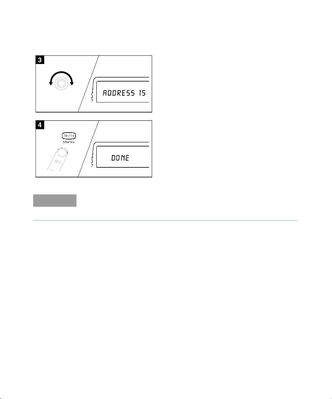
3 Rotate the knob to view the choices on this level
NOTE
of the menu. When you reach the end of the list,
rotate the knob in the opposite direction to view
all of the other choices.
The current selection is highlighted for emphasis.
All other choices are dimmed.
4 Press the same menu key again to accept the
change and exit the menu. A brief confirmation
message is displayed.
Tip: To review the current configuration of a specific menu, press the
menu key several times. A message NO CHANGES is displayed when you
exit the menu.
Keysight 34970A/34972A Service Guide 13
Page 14

Display Annunciators
SCAN
MON
VIEW Scanned readings, alarms, errors, or relay cycles are being viewed.
CONFIG Channel configuration is in progress on displayed channel.
ADRS Instrument is addressed to listen or talk over the remote interface.
RMT Instrument is in remote mode (remote interface).
ERROR
EXT Instrument is configured for an external scan interval.
ONCE
MEM (34970A) Reading memory overflow; new readings will overwrite the oldest readings.
MEM (34972A)
AUTO (34972A) USB logging is active.
LAST Viewed data is the last reading stored during most recent scan.
MIN Viewed data is the minimum reading stored during most recent scan.
MAX Viewed data is the maximum reading stored during most recent scan.
Scan is in progress or enabled. Press and hold again to turn off.
Monitor mode is enabled. Press again to turn off.
Measurement is in progress.
Hard ware or remote interface errors are detected. Press to read errors.
Scan Once mode is enabled. Press to initiate and hold key to disable.
A USB drive is connected to the instrument (annunciator on), or data is being
written to or read from the USB drive (annunciator flashing).
SHIFT
4W 4-wire function is in use on displayed channel.
OC Offset compensation is enabled on displayed channel.
has been pressed. Press again to turn off.
14 Keysight 34970A/34972A Service Guide
Page 15

Alarms are enabled on displayed channel.
Mx+B scaling is enabled on displayed channel.
HI or LO alarm condition has occurred on indicated alarms.
New serial number prefixes start with MY59000101 and SG59000101.
Keysight 34970A/34972A Service Guide 15
Page 16

The 34970A Rear Panel at a Glance
WARNING
1 Slot Identifier (100,200, 300)
2 Ext Trig Input / Alarm Outputs / Channel
Advance Input / Channel Closed Output
3 RS-232 Interface Connector
Use the Menu to:
– Select the GPIB or RS-232 interface (see Chapter 2).
– Set the GPIB address (see Chapter 2).
– Set the RS-232 baud rate, parity, and flow control mode (see Chapter 2).
4 Power-Line Fuse-Holder Assembly
5 Power-Line Voltage Setting
6 Chassis Ground Screw
7 GPIB (IEEE-488) Interface Connector
For protection from electrical shock, the power cord ground must not be
defeated. If only a two-contact electrical outlet is available, connect the
instrument’s chassis ground screw (see above) to a good earth ground.
16 Keysight 34970A/34972A Service Guide
Page 17

The 34972A Rear Panel at a Glance
WARNING
For serial number MY59000100 & SG59000100 and below.
Keysight 34970A/34972A Service Guide 17
1 Slot Identifier (100,200, 300)
2 Chassis Ground Screw
3 Ext Trig Input / Alarm Outputs / Channel
Advance Input / Channel Closed Output
Use the Menu to:
– Select and configure the LAN and USB interfaces (see Chapter 2).
[a] Under some conditions, while using the USB interface with the 34972A, you may experience connection or data
loss in the presence of an electrical transient from the main power line. You can re-establish the USB
communication by performing a reboot (cycle power) on the instrument. You can make the USB connection less
susceptible to a potential power line transient by inserting a USB hub in the connection between the computer and
the instrument.
4 Power-Line Fuse-Holder Assembly
5 LAN Connector
6 USB Drive Connector
7 USB Interface Connector
[a]
For protection from electrical shock, the power cord ground must not be
defeated. If only a two-contact electrical outlet is available, connect the
instrument’s chassis ground screw (see above) to a good earth ground.
Page 18

For serial number MY59000101 & SG59000101 and above.
WARNING
18 Keysight 34970A/34972A Service Guide
1 Slot Identifier (100,200, 300)
2 Chassis Ground Screw
3 Ext Trig Input / Alarm Outputs / Channel
Advance Input / Channel Closed Output
Use the Menu to:
– Select and configure the LAN and USB interfaces (see Chapter 2).
4 Power-Line Fuse-Holder Assembly
5 LAN Connector
6 USB Drive Connector
7 USB Interface Connector
For protection from electrical shock, the power cord ground must not be
defeated. If only a two-contact electrical outlet is available, connect the
instrument’s chassis ground screw (see above) to a good earth ground.
Page 19

The Plug-In Modules at a Glance
For complete specifications on each plug-in modules, refer to the module
sections in Chapter 1.
34901A 20-Channel Armature Multiplexer
– 20 channels of 300 V switching
– Two channels for DC or AC current measurements (100 nA to 1A)
– Built-in thermocouple reference junction
– Switching speed of up to 60 channels per second
– Connects to the internal multimeter
– For detailed information and a module diagram, see page 151.
Each of the 20 channels switches both HI and LO inputs, thus providing fully
isolated inputs to the internal multimeter. The module is divided into two banks of
10 two-wire channels each. When making four-wire resistance measurements,
channels from Bank A are automatically paired with channels from Bank B. Two
additional fused channels are included on the module (22 channels total) for
making calibrated DC or AC current measurements with the internal multimeter
(external shunt resistors are not required). You can close multiple channels on this
module only if you have not configured any channels to be part of the scan list.
Otherwise, all channels on the module are break-before-make.
34902A 16-Channel Reed Multiplexer
– 16 channels of 300 V switching
– Built-in thermocouple reference junction
– Switching speed of up to 250 channels per second
– Connects to the internal multimeter
– For detailed information and a module diagram, see page 153.
Use this module for high-speed scanning and high-throughput automated test
applications. Each of the 16 channels switches both HI and LO inputs, thus
providing fully isolated inputs to the internal multimeter. The module is divided
into two banks of eight two-wire channels each. When making four-wire
resistance measurements, channels from Bank A are automatically paired with
channels from Bank B. You can close multiple channels on this module only if you
Keysight 34970A/34972A Service Guide 19
Page 20

have not configured any channels to be part of the scan list. Otherwise, all
channels on the module are break-before-make.
34903A 20-Channel Actuator / General-Purpose Switch
– 300 V, 1 A actuation and switching
– SPDT (Form C) latching relays
– Breadboard area for custom circuits
– For detailed information and a module diagram, see page 155.
Use this module for those applications that require high-integrity contacts or
quality connections of non-multiplexed signals. This module can switch 300 V, 1 A
(50 W maximum switch power) to your device under test or to actuate external
devices. Screw terminals on the module provide access to the Normally-Open,
Normally-Closed, and Common contacts for each of the 20 switches. A
breadboard area is provided near the screw terminals to implement custom
circuitry, such as simple filters, snubbers, or voltage dividers.
34904A 4x8 Two-Wire Matrix Switch
– 32 two-wire crosspoints
– Any combination of inputs and outputs can be connected at a time
– 300 V, 1 A switching
– For detailed information and a module diagram, see page 156.
Use this module to connect multiple instruments to multiple points on your device
under test at the same time. You can connect rows and columns between multiple
modules to build larger matrices such as 8x8 and 4x16, with up to 96 crosspoints
in a single mainframe.
34905/6A Dual 4-Channel RF Multiplexers
– 34905A (50Ω) / 34906A (75Ω)
– 2 GHz bandwidth with on-board SMB connections
– 1 GHz bandwidth with SMB-to-BNC adapter cables provided
– For detailed information and a module diagram, see page 158.
20 Keysight 34970A/34972A Service Guide
Page 21

These modules offer wideband switching capabilities for high frequency and
pulsed signals. Each module is organized in two independent banks of 4-to-1
multiplexers. Both modules offer low crosstalk and excellent insertion loss
performance. To create larger RF multiplexers, you can cascade multiple banks
together. Only one channel in each bank may be closed at a time.
34907A Multifunction Module
– Two 8-bit Digital Input/Output ports, 400 mA sink, 42 V open collector
– 100 kHz Totalize input with 1 Vpp sensitivity
– Two 16-bit, ±12 V Calibrated Analog Outputs
– For detailed information and module block diagrams, see page 162.
Use this module to sense status and control external devices such as solenoids,
power relays, and microwave switches. For greater flexibility, you can read digital
inputs and the count on the totalizer during a scan.
34908A 40-Channel Single-Ended Multiplexer
– 40 channels of 300 V single-ended (common LO) switching
– Built-in thermocouple reference junction
– Switching speed of up to 60 channels per second
– Connects to the internal multimeter
– For detailed information and a module diagram, see page 160.
Use this module for high-density switching applications which require single-wire
inputs with a common LO. All relays are break-before-make to ensure that only
one relay is connected at any time.
Keysight 34970A/34972A Service Guide 21
Page 22

In This Book
Specifications
and plug-in modules.
Quick Start
front-panel features.
Front-Panel Overview
describes some of the instrument’s menu features.
Calibration Procedures
adjustment procedures for the instrument.
Theory of Operation
to the operation the instrument.
Service
Technologies for servicing, or for servicing it yourself. It also contains a list of
replaceable parts.
If you have questions relating to the operation of the 34970A/34972A, call
1-800-452-4844 in the United States, or contact your nearest Keysight
Technologies Sales Office.
If your 34970A/34972A fails within one year of original purchase, Keysight will
replace it free of charge. Call 1-800-829-4444 and select “Option 3” followed by
“Option 1”.
Chapter 6 provides guidelines for returning your instrument to Keysight
Chapter 1 lists the technical specifications for the mainframe
Chapter 2 helps you get familiar with a few of the instrument’s
Chapter 3 introduces you to the front-panel menus and
Chapter 4 provides calibration, verification, and
Chapter 5 describes block and circuit level theory related
22 Keysight 34970A/34972A Service Guide
Page 23

Table of Contents
Software Updates/Licenses . . . . . . . . . . . . . . . . . . . . . . . . . . . . . . . . . . .3
Safety Symbols . . . . . . . . . . . . . . . . . . . . . . . . . . . . . . . . . . . . . . . . . . . . .4
Safety Considerations . . . . . . . . . . . . . . . . . . . . . . . . . . . . . . . . . . . . . . . .5
General . . . . . . . . . . . . . . . . . . . . . . . . . . . . . . . . . . . . . . . . . . . . . . . . .5
Before Applying Power . . . . . . . . . . . . . . . . . . . . . . . . . . . . . . . . . . . .5
Ground the Instrument . . . . . . . . . . . . . . . . . . . . . . . . . . . . . . . . . . . .5
Do Not Operate in an Explosive Atmosphere . . . . . . . . . . . . . . . . . . .5
Do Not Remove the Instrument Cover . . . . . . . . . . . . . . . . . . . . . . . .6
Do Not Modify the Instrument . . . . . . . . . . . . . . . . . . . . . . . . . . . . . . .6
In Case of Damage . . . . . . . . . . . . . . . . . . . . . . . . . . . . . . . . . . . . . . . .6
Environmental Conditions . . . . . . . . . . . . . . . . . . . . . . . . . . . . . . . . . . . .7
Regulatory Markings . . . . . . . . . . . . . . . . . . . . . . . . . . . . . . . . . . . . . . . . .8
Waste Electrical and Electronic Equipment (WEEE) Directive . . . . . . . .9
Product category . . . . . . . . . . . . . . . . . . . . . . . . . . . . . . . . . . . . . . . . .9
Sales and Technical Support . . . . . . . . . . . . . . . . . . . . . . . . . . . . . . . . . .9
The Front Panel at a Glance . . . . . . . . . . . . . . . . . . . . . . . . . . . . . . . . . .11
The Front-Panel Menu at a Glance . . . . . . . . . . . . . . . . . . . . . . . . . . . .12
Display Annunciators . . . . . . . . . . . . . . . . . . . . . . . . . . . . . . . . . . . . . . .14
The 34970A Rear Panel at a Glance . . . . . . . . . . . . . . . . . . . . . . . . . . .16
The 34972A Rear Panel at a Glance . . . . . . . . . . . . . . . . . . . . . . . . . . .17
The 34972A Rear Panel at a Glance . . . . . . . . . . . . . . . . . . . . . . . . . . .18
The Plug-In Modules at a Glance . . . . . . . . . . . . . . . . . . . . . . . . . . . . . . 19
In This Book . . . . . . . . . . . . . . . . . . . . . . . . . . . . . . . . . . . . . . . . . . . . . . .22
1Specifications
2Quick Start
Quick Start . . . . . . . . . . . . . . . . . . . . . . . . . . . . . . . . . . . . . . . . . . . . . . . 32
To Prepare the Instrument for Use . . . . . . . . . . . . . . . . . . . . . . . . . . . . .33
To Connect Wiring to a Module . . . . . . . . . . . . . . . . . . . . . . . . . . . . . . .34
Keysight 34970A/34972A Service Guide 23
Page 24

To Set the Time and Date . . . . . . . . . . . . . . . . . . . . . . . . . . . . . . . . . . . 36
To Configure a Measurement Channel . . . . . . . . . . . . . . . . . . . . . . . . . 37
To Monitor a Single Channel . . . . . . . . . . . . . . . . . . . . . . . . . . . . . . . . . 38
To Close a Channel . . . . . . . . . . . . . . . . . . . . . . . . . . . . . . . . . . . . . . . . 39
If the Instrument Does Not Turn On . . . . . . . . . . . . . . . . . . . . . . . . . . . 41
. . . . . . . . . . . . . . . . . . . . . . . . . . . . . . . . . . . . . . . . . . . . . . . . . . . . . . . . 43
To Adjust the Carrying Handle . . . . . . . . . . . . . . . . . . . . . . . . . . . . . . . . 44
To Rack Mount the Instrument . . . . . . . . . . . . . . . . . . . . . . . . . . . . . . . 45
3 Front-Panel Overview
Front-Panel Overview . . . . . . . . . . . . . . . . . . . . . . . . . . . . . . . . . . . . . . . 48
Front-Panel Menu Reference . . . . . . . . . . . . . . . . . . . . . . . . . . . . . . . . . 49
To Unsecure for Calibration . . . . . . . . . . . . . . . . . . . . . . . . . . . . . . . . . . 52
To Secure Against Calibration . . . . . . . . . . . . . . . . . . . . . . . . . . . . . . . . 53
To Change the Security Code . . . . . . . . . . . . . . . . . . . . . . . . . . . . . . . . 54
Error Messages . . . . . . . . . . . . . . . . . . . . . . . . . . . . . . . . . . . . . . . . . . . . 55
To Perform a Zero Adjustment . . . . . . . . . . . . . . . . . . . . . . . . . . . . . . . . 56
To Apply Mx+B Scaling to Measurements . . . . . . . . . . . . . . . . . . . . . . . 57
To Read the Relay Cycle Count . . . . . . . . . . . . . . . . . . . . . . . . . . . . . . . 58
To Read a Digital Input Port . . . . . . . . . . . . . . . . . . . . . . . . . . . . . . . . . . 59
To Write to a Digital Output Port . . . . . . . . . . . . . . . . . . . . . . . . . . . . . . 60
To Read the Totalizer Count . . . . . . . . . . . . . . . . . . . . . . . . . . . . . . . . . 61
To Output a DC Voltage . . . . . . . . . . . . . . . . . . . . . . . . . . . . . . . . . . . . . 62
4 Calibration Procedures
Calibration Procedures . . . . . . . . . . . . . . . . . . . . . . . . . . . . . . . . . . . . . . 64
Keysight Technologies Calibration Services . . . . . . . . . . . . . . . . . . . . . 66
Calibration Interval . . . . . . . . . . . . . . . . . . . . . . . . . . . . . . . . . . . . . . . . . 66
Adjustment is Recommended . . . . . . . . . . . . . . . . . . . . . . . . . . . . . . 66
Time Required for Calibration . . . . . . . . . . . . . . . . . . . . . . . . . . . . . . . . 67
Automating Calibration Procedures . . . . . . . . . . . . . . . . . . . . . . . . . . . 67
24 Keysight 34970A/34972A Service Guide
Page 25

Recommended Test Equipment . . . . . . . . . . . . . . . . . . . . . . . . . . . . . . .68
Input Connections . . . . . . . . . . . . . . . . . . . . . . . . . . . . . . . . . . . . . . . . . .69
Calibration Security . . . . . . . . . . . . . . . . . . . . . . . . . . . . . . . . . . . . . . . .71
To Unsecure the Instrument Without the Security Code . . . . . . . . .72
Calibration Message . . . . . . . . . . . . . . . . . . . . . . . . . . . . . . . . . . . . . . . .74
Calibration Count . . . . . . . . . . . . . . . . . . . . . . . . . . . . . . . . . . . . . . . . . .74
Calibration Procedure . . . . . . . . . . . . . . . . . . . . . . . . . . . . . . . . . . . . . . .75
Aborting a Calibration in Progress . . . . . . . . . . . . . . . . . . . . . . . . . . . . .75
Test Considerations . . . . . . . . . . . . . . . . . . . . . . . . . . . . . . . . . . . . . . . .76
Performance Verification Tests . . . . . . . . . . . . . . . . . . . . . . . . . . . . . . . .77
Self-Test . . . . . . . . . . . . . . . . . . . . . . . . . . . . . . . . . . . . . . . . . . . . . . .78
Quick Performance Check . . . . . . . . . . . . . . . . . . . . . . . . . . . . . . . . .79
Performance Verification Tests . . . . . . . . . . . . . . . . . . . . . . . . . . . . .79
Internal DMM Verification Tests . . . . . . . . . . . . . . . . . . . . . . . . . . . . . . .80
Zero Offset Verification . . . . . . . . . . . . . . . . . . . . . . . . . . . . . . . . . . .80
Gain Verification . . . . . . . . . . . . . . . . . . . . . . . . . . . . . . . . . . . . . . . . .82
Optional AC Performance Verification Tests . . . . . . . . . . . . . . . . . . . . .87
Internal DMM Adjustments . . . . . . . . . . . . . . . . . . . . . . . . . . . . . . . . . . .88
Zero Adjustment . . . . . . . . . . . . . . . . . . . . . . . . . . . . . . . . . . . . . . . .88
Gain Adjustment . . . . . . . . . . . . . . . . . . . . . . . . . . . . . . . . . . . . . . . .89
–10 VDC Adjustment Procedure (Optional) . . . . . . . . . . . . . . . . . . . . . .92
Plug-in Module Test Considerations . . . . . . . . . . . . . . . . . . . . . . . . . . .94
Relay Verification . . . . . . . . . . . . . . . . . . . . . . . . . . . . . . . . . . . . . . . . . .96
Relay Cycle Count . . . . . . . . . . . . . . . . . . . . . . . . . . . . . . . . . . . . . . .96
(Optional) 34901A Relay Contact Resistance Verification . . . . . . . .97
(Optional) 34902A Relay Contact Resistance Verification . . . . . . .104
(Optional) 34903A Relay Contact Resistance Verification . . . . . . .109
(Optional) 34904A Relay Contact Resistance Verification . . . . . . .110
(Optional) 34905/06A Relay Contact Resistance Verification . . . .113
(Optional) 34908A Relay Contact Resistance Verification . . . . . . .114
Thermocouple Reference Junction (Optional) . . . . . . . . . . . . . . . . . . .120
Thermocouple Reference Junction Verification . . . . . . . . . . . . . . .120
Keysight 34970A/34972A Service Guide 25
Page 26

Thermocouple Reference Junction Adjustments . . . . . . . . . . . . . . 121
34907A Analog Output . . . . . . . . . . . . . . . . . . . . . . . . . . . . . . . . . . . . 123
Analog Output Verification Test . . . . . . . . . . . . . . . . . . . . . . . . . . . 123
Analog Output Adjustment . . . . . . . . . . . . . . . . . . . . . . . . . . . . . . . 124
5Theory of Operation
Theory of Operation . . . . . . . . . . . . . . . . . . . . . . . . . . . . . . . . . . . . . . . 126
System Block Diagram . . . . . . . . . . . . . . . . . . . . . . . . . . . . . . . . . . . . . 127
Floating Logic . . . . . . . . . . . . . . . . . . . . . . . . . . . . . . . . . . . . . . . . . . . . 128
Memory . . . . . . . . . . . . . . . . . . . . . . . . . . . . . . . . . . . . . . . . . . . . . . . . . 131
Earth-Referenced Logic . . . . . . . . . . . . . . . . . . . . . . . . . . . . . . . . . . . . 132
Power Supplies . . . . . . . . . . . . . . . . . . . . . . . . . . . . . . . . . . . . . . . . . . . 133
Front Panel . . . . . . . . . . . . . . . . . . . . . . . . . . . . . . . . . . . . . . . . . . . . . . 135
Backplane . . . . . . . . . . . . . . . . . . . . . . . . . . . . . . . . . . . . . . . . . . . . . . . 136
Analog Bus . . . . . . . . . . . . . . . . . . . . . . . . . . . . . . . . . . . . . . . . . . . 136
Digital Bus . . . . . . . . . . . . . . . . . . . . . . . . . . . . . . . . . . . . . . . . . . . . 136
Internal DMM . . . . . . . . . . . . . . . . . . . . . . . . . . . . . . . . . . . . . . . . . . . . 137
DMM Block Diagram . . . . . . . . . . . . . . . . . . . . . . . . . . . . . . . . . . . . 137
Input . . . . . . . . . . . . . . . . . . . . . . . . . . . . . . . . . . . . . . . . . . . . . . . . . 138
Input Amplifier . . . . . . . . . . . . . . . . . . . . . . . . . . . . . . . . . . . . . . . . . 139
Ohms Current Source . . . . . . . . . . . . . . . . . . . . . . . . . . . . . . . . . . . 141
AC Circuit . . . . . . . . . . . . . . . . . . . . . . . . . . . . . . . . . . . . . . . . . . . . . 142
A-to-D Converter . . . . . . . . . . . . . . . . . . . . . . . . . . . . . . . . . . . . . . 144
Switch Modules . . . . . . . . . . . . . . . . . . . . . . . . . . . . . . . . . . . . . . . . . . 146
Switch Module Control . . . . . . . . . . . . . . . . . . . . . . . . . . . . . . . . . . 147
Relay Drivers . . . . . . . . . . . . . . . . . . . . . . . . . . . . . . . . . . . . . . . . . . 149
34901A . . . . . . . . . . . . . . . . . . . . . . . . . . . . . . . . . . . . . . . . . . . . . . 151
34902A . . . . . . . . . . . . . . . . . . . . . . . . . . . . . . . . . . . . . . . . . . . . . . 153
34903A . . . . . . . . . . . . . . . . . . . . . . . . . . . . . . . . . . . . . . . . . . . . . . 155
34904A . . . . . . . . . . . . . . . . . . . . . . . . . . . . . . . . . . . . . . . . . . . . . . 156
34905A/34906A . . . . . . . . . . . . . . . . . . . . . . . . . . . . . . . . . . . . . . . 158
34908A . . . . . . . . . . . . . . . . . . . . . . . . . . . . . . . . . . . . . . . . . . . . . . 160
Multifunction Module . . . . . . . . . . . . . . . . . . . . . . . . . . . . . . . . . . . . . . 162
26 Keysight 34970A/34972A Service Guide
Page 27

Multifunction Control . . . . . . . . . . . . . . . . . . . . . . . . . . . . . . . . . . . .162
Totalizer . . . . . . . . . . . . . . . . . . . . . . . . . . . . . . . . . . . . . . . . . . . . . .164
Analog Output . . . . . . . . . . . . . . . . . . . . . . . . . . . . . . . . . . . . . . . . .165
Digital I/O . . . . . . . . . . . . . . . . . . . . . . . . . . . . . . . . . . . . . . . . . . . . .166
6Service
Service . . . . . . . . . . . . . . . . . . . . . . . . . . . . . . . . . . . . . . . . . . . . . . . . .170
Operating Checklist . . . . . . . . . . . . . . . . . . . . . . . . . . . . . . . . . . . . . . .171
Types of Service Available . . . . . . . . . . . . . . . . . . . . . . . . . . . . . . . . . .172
Repackaging for Shipment . . . . . . . . . . . . . . . . . . . . . . . . . . . . . . . . . .173
Cleaning . . . . . . . . . . . . . . . . . . . . . . . . . . . . . . . . . . . . . . . . . . . . . . . .173
Electrostatic Discharge (ESD) Precautions . . . . . . . . . . . . . . . . . . . . .174
Surface Mount Repair . . . . . . . . . . . . . . . . . . . . . . . . . . . . . . . . . . . . . .174
To Replace the Power-Line Fuse . . . . . . . . . . . . . . . . . . . . . . . . . . . . .175
Troubleshooting Hints . . . . . . . . . . . . . . . . . . . . . . . . . . . . . . . . . . . . .175
Self-Test Procedures . . . . . . . . . . . . . . . . . . . . . . . . . . . . . . . . . . . . . .179
Disassembly . . . . . . . . . . . . . . . . . . . . . . . . . . . . . . . . . . . . . . . . . . . . .184
General Disassembly . . . . . . . . . . . . . . . . . . . . . . . . . . . . . . . . . . . .185
Internal DMM Disassembly . . . . . . . . . . . . . . . . . . . . . . . . . . . . . . .186
Front Panel Disassembly . . . . . . . . . . . . . . . . . . . . . . . . . . . . . . . . .187
Additional Chassis Disassembly . . . . . . . . . . . . . . . . . . . . . . . . . . .188
Plug-In Module Disassembly . . . . . . . . . . . . . . . . . . . . . . . . . . . . . .189
Recyclable Parts . . . . . . . . . . . . . . . . . . . . . . . . . . . . . . . . . . . . . . .191
Replaceable Parts . . . . . . . . . . . . . . . . . . . . . . . . . . . . . . . . . . . . . .194
To Order Replaceable Parts . . . . . . . . . . . . . . . . . . . . . . . . . . . . . . .194
Parts List for 34970A/34972A and 34901A . . . . . . . . . . . . . . . . . .194
Keysight 34970A/34972A Service Guide 27
Page 28

THIS PAGE HAS BEEN INTENTIONALLY LEFT BLANK.
28 Keysight 34970A/34972A Service Guide
Page 29

Keysight 34970A/34972A Data Acquisition/Switch Unit
Service Guide
1 Specifications
For the specifications and characteristics of the 34970A/34972A Data
Acquisition/Switch Unit, refer to the datasheet at
http://literature.cdn.keysight.com/litweb/pdf/5965-5290EN.pdf
29
Page 30

1 Specifications
THIS PAGE HAS BEEN INTENTIONALLY LEFT BLANK.
30 Keysight 34970A/34972A Service Guide
Page 31

Keysight 34970A/34972A Data Acquisition/Switch Unit
Service Guide
2 Quick Start
Quick Start 32
To Prepare the Instrument for Use 33
To Connect Wiring to a Module 34
To Set the Time and Date 36
To Configure a Measurement Channel 37
To Monitor a Single Channel 38
To Close a Channel 39
If the Instrument Does Not Turn On 41
To Adjust the Carrying Handle 44
To Rack Mount the Instrument 45
31
Page 32

2Quick Start
Quick Start
One of the first things to do with your instrument is to become acquainted with
the front panel. We have written the exercises in this chapter to prepare the
instrument for use and help you get familiar with some of its front-panel
operations.
The front panel has several groups of keys to select various functions and
operations. A few keys have a shifted function printed in blue below the key. To
perform a shifted function, press (the SHIFT annunciator will turn on). Then,
press the key that has the desired label below it. For example, to select the Utility
Menu, press .
If you accidentally press , just press it again to turn off the SHIFT
annunciator.
This chapter is divided into the following sections:
– “To Prepare the Instrument for Use” on page 33
– “To Connect Wiring to a Module” on page 34
– “To Set the Time and Date” on page 36
– “To Configure a Measurement Channel” on page 37
– “To Monitor a Single Channel” on page 38
– “To Close a Channel” on page 39
– “If the Instrument Does Not Turn On” on page 41
– “” on page 43
– “To Rack Mount the Instrument” on page 45
32 Keysight 34970A/34972A Service Guide
Page 33

To Prepare the Instrument for Use
1 Check the list of supplied items.
Verify that you have received the following items with your instrument. If
anything is missing, contact your nearest Keysight Technologies Sales Office.
–One power cord.
–One User’s Guide.
–This Service Guide.
–One Quick Reference Guide.
– Certificate of Calibration (if you ordered the internal DMM).
– BenchLink Data Logger 3 Software CD-ROM.
– Quick Start Package (if you ordered the internal DMM):
– One RS-232 cable.
– One J-type thermocouple and a flatblade screwdriver.
– Any plug-in modules that you ordered are delivered in a separate shipping
container.
2 Verify that the fuse on the back is set to the proper voltage range for your
AC power.
3 Connect the power cord and turn on the instrument.
Quick Start 2
The front-panel display will light up briefly while the instrument performs its
power-on self-test. The instrument initially powers up with all measurement
channels turned off. To review the power-on display with all annunciators
turned on, hold down
does not turn on properly, see page 41.
4 Perform a complete self-test.
The complete self-test performs a more extensive set of tests than those
performed at power-on. Hold down as you turn on the instrument and
hold down the key until you hear a long beep. The self-test will begin when
you release the key following the beep.
Keysight 34970A/34972A Service Guide 33
as you turn on the instrument. If the instrument
Page 34

2Quick Start
– For detailed information on each module, refer to the
34970A/34972A User’s Guide.
– To reduce wear on the internal DMM relays, wire like
functions on adjacent channels.
– Use shielded twisted pair PTFE insulated cables to
reduce settling and noise errors.
– The diagrams on the next page show how to connect
wiring to a multiplexer module for each measurement
function.
20 AWG Typical
6 mm
4 Replace the module cover.
2 Connect wiring to the screw terminals.
Wiring Hints...
Slot Channel
Channel Number:
1 Remove the module cover.
3 Route wiring through strain relief.
5 Install the module into mainframe.
Cable Tie Wrap
(optional)
To Connect Wiring to a Module
34 Keysight 34970A/34972A Service Guide
Page 35

Quick Start 2
Thermocouple
2-Wire Ohms / RTD / Thermistor
Thermocouple Types: B, E, J, K, N, R, S, T
See the 34970A/34972A User’s Guide for
Ranges: 100, 1 k, 10 k, 100 k, 1 M, 10 M, 100 M
Ω
RTD Types: 0.00385, 0.00391
Thermistor Types, 2.2 k, 5 k, 10 k
DC Current / AC Current
Valid only on channels 21 and 22 on the 34901A
Ranges: 10 mA, 100 mA, 1A
Channel n (source) is automatically paired with Channel n
+10 (sense) on the 34901A, or
Channel n +8 (sense) on the 34902A.
Ranges: 100, 1 k, 10 k, 100 k, 1 M, 10 M, 100 MΩ
RTD Types: 0.00385, 0.00391
DC Voltage / AC Voltage / Frequency
Ranges: 100 mV, 1 V, 10 V, 100 V, 300 V
4-Wire Ohms / RTD
thermocouple color codes.
Keysight 34970A/34972A Service Guide 35
Page 36

2Quick Start
To Set the Time and Date
All readings during a scan are automatically time stamped and stored in
non-volatile memory. In addition, alarm data is time stamped and stored in a
separate non-volatile memory queue.
1 Set the time of day.
Use and to select the field to modify and turn the knob to change the
value. You can also edit the AM/PM field.
TIME 03:45 PM
2 Set the date.
Use and to select the field to modify and turn the knob to change the
value.
JUN 01 2002
36 Keysight 34970A/34972A Service Guide
Page 37

To Configure a Measurement Channel
NOTE
NOTE
Use this general procedure to configure a measurement channel.
1 Select the channel.
Turn the knob until the desired channel is shown on the right side of
front-panel display. The channel number is a three-digit number; the left-most
digit represents the slot number (100, 200, or 300) and the two digits on the
right indicate the channel number (102, 110, etc.).
You can use and to skip to the beginning of the previous or next slot.
2 Select the measurement parameters for the selected channel.
Use the knob to scroll through the measurement choices on each level of the
menu. When you press to make your selection, the menu automatically
guides you through all relevant choices to configure a measurement on the
selected function. When you have finished configuring the parameters, you are
automatically exited from the menu.
The present selection (or default) is displayed in full bright for easy
identification. When you make a different selection, the new choice is shown in
full bright and it becomes the default selection. The order of the choices
always remains the same; however, you always enter the menu at the current
(full bright) setting for each parameter.
Quick Start 2
The menu will time-out after about 20 seconds of inactivity and any changes
made previously will take effect.
Keysight 34970A/34972A Service Guide 37
Page 38

2Quick Start
To Monitor a Single Channel
You can use the Monitor function to continuously take readings on a single
channel, even during a scan. This feature is used during front panel calibration
procedures.
1 Select the channel to be monitored.
Only one channel can be monitored at a time but you can change the channel
being monitored at any time by turning the knob.
2 Enable monitoring on the selected channel.
Any channel that can be “read” by the instrument can be monitored (the MON
annunciator turns on). This includes any combination of temperature, voltage,
resistance, current, frequency, or period measurements on multiplexer
channels. You can also monitor a digital input port or the totalizer count on the
multifunction module.
To disable monitoring, press again.
38 Keysight 34970A/34972A Service Guide
Page 39
To Close a Channel
NOTE
,
On the multiplexer and switch modules, you can close and open individual relays
on the module. However, note that if you have already configured any multiplexer
channels for scanning, you cannot independently close and open individual relays
on that module.
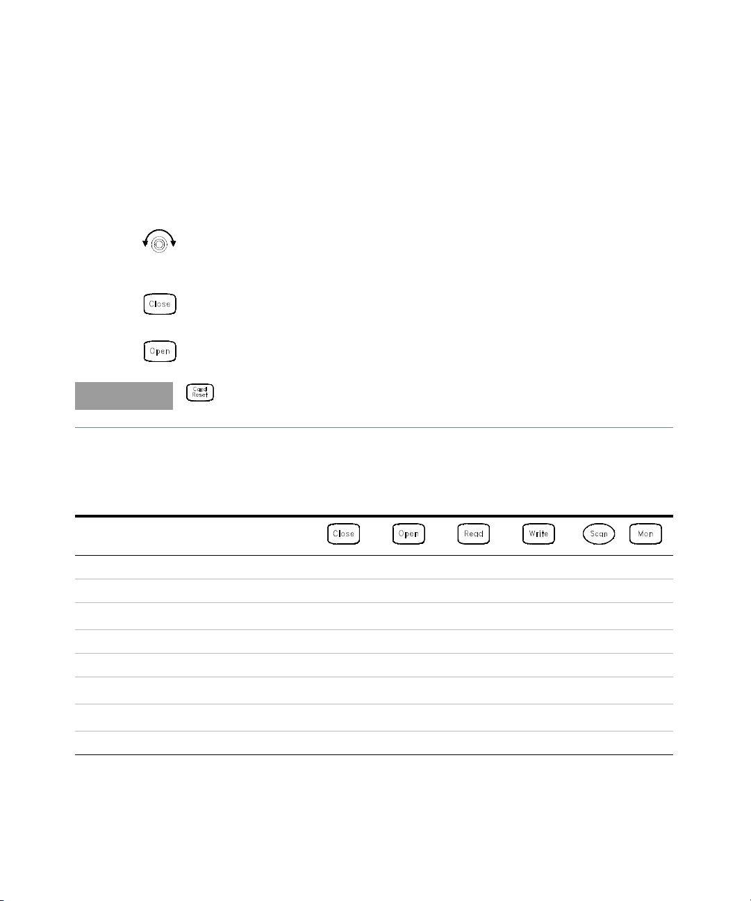
1 Select the channel.
Turn the knob until the desired channel is shown on the right side of
front-panel display. For this example, select channel 213.
2 Close the selected channel.
3 Open the selected channel.
will sequentially open all channels on the mod ule in the selected slot.
The table below shows the low-level control operations available for each of
the plug-in modules.
Quick Start 2
Plug-In Mod ule
34901A 20-Channel Mux YYY Y
34902A 16-Channel Mux YYY Y
34908A 40-Channel Single-Ended Mux
34903A 20-Channel Actuator YY
34904A 4x8 Matrix YY
34905A Dual 4-Channel RF Mux (50Ω)
34906A Dual 4-Channel RF Mux (75Ω)
34907A Multifunction Module (DIO) YY Y
[a]
[b]
[b]
YYY Y
Y
Y
Keysight 34970A/34972A Service Guide 39
Page 40

2Quick Start
,
Plug-In Mod ule
34907A Multifunction Module (Totalizer) YY
34907A multifunction Module (DAC) Y
[a] Only one channel can be closed at a time on this module.
[b] Only one channel in each bank can be closed at a time on this module.
40 Keysight 34970A/34972A Service Guide
Page 41

If the Instrument Does Not Turn On
NOTE
NOTE
Use the following steps to help solve problems you might encounter when turning
on the instrument.
1 Verify that there is AC power to the instrument.
First, verify that the power cord is firmly plugged into the power receptacle on
the rear panel of the instrument. You should also make sure that the power
source you plugged the instrument into is energized. Then, verify that the
instrument is turned on.
The On/Standby switch is located on the lower left side of the front panel.
2 Verify the power-line voltage setting.
The line voltage is set to the proper value for your country when the
instrument is shipped from the factory. Change the voltage setting if it is not
correct. The settings are: 100, 120, 220, or 240 VAC.
– For 127 VAC operation, use the 120 VAC setting.
– For 230 VAC operation, use the 220 VAC setting.
Quick Start 2
See the next page if you need to change the line voltage setting.
3 Verify that the power-line fuse is good.
The instrument is shipped from the factory with a 500 mA fuse installed. This is
the correct fuse for all line voltages.
See the next page if you need to replace the power-line fuse.
To replace the 500 mAT, 250 V fuse, order Keysight part number 2110-0458.
Keysight 34970A/34972A Service Guide 41
Page 42

2Quick Start
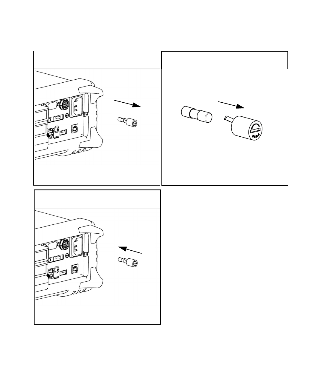
3 Rotate the line-voltage selector until the
correct voltage appears in the window.
1 Remove the power cord. Remove the
fuse-holder assembly from the rear panel.
100, 120 (127), 220 (230), or 240 VAC
2 Remove the line voltage selector from the
assembly.
4 Replace the fuse-holder assembly in the rear
panel.
Fuse: 500 mAT (for all line voltages)
Keysight Part Number: 2110-0458
Verify that the correct line voltage is selected and the power-line fuse is good.
42 Keysight 34970A/34972A Service Guide
Page 43
Quick Start 2
1 Remove the power cord. Remove the
fuse-holder assembly from the rear panel.
3 Replace the fuse-holder assembly in the rear
panel.
2 Remove the fuse from the assembly.
Fuse: 250 maT (for all line voltages)
Keysight Part Number: 2110-1704
New serial number prefixes start with MY59000101 and SG59000101.
Keysight 34970A/34972A Service Guide 43
Page 44

2Quick Start
Bench-top viewing position Carrying position
To Adjust the Carrying Handle
To adjust the position, grasp the handle by the sides and pull outward. Then,
rotate the handle to the desired position.
44 Keysight 34970A/34972A Service Guide
Page 45

To Rack Mount the Instrument
NOTE
To remove the handle, rotate it to the vertical position and pull the ends outward.
Front Rear (bottom view)
To remove the rubber bumper, stretch a corner and then slide it off.
You can mount the instrument in a standard 19-inch rack cabinet using one of
three optional kits available. Instructions and mounting hardware are included
with each rack-mounting kit. Any Keysight System II instrument of the same size
can be rack-mounted beside the 34970A/34972A.
Remove the carrying handle, and the front and rear rubber bumpers, before
rack-mounting the instrument.
Quick Start 2
Keysight 34970A/34972A Service Guide 45
Page 46

2Quick Start
To rack mount a single instrument, order adapter kit 5063-9240.
To rack mount two instruments side-by-side, order lock-link kit 5061-9694 and
flange kit 5063-9212. Be sure to use the support rails inside the rack cabinet.
To install one or two instruments in a sliding support shel f, order shelf 5063-9255,
and slide kit 1494-0015 (for a single instrument, also order filler panel 5002-3999).
46 Keysight 34970A/34972A Service Guide
Page 47

Keysight 34970A/34972A Data Acquisition/Switch Unit
Service Guide
3 Front-Panel Overview
Front-Panel Overview 48
Front-Panel Menu Reference 49
To Unsecure for Calibration 52
To Secure Against Calibration 53
To Change the Security Code 54
Error Messages 55
To Perform a Zero Adjustment 56
To Apply Mx+B Scaling to Measurements 57
To Read the Relay Cycle Count 58
To Read a Digital Input Port 59
To Write to a Digital Output Port 60
To Read the Totalizer Count 61
To Output a DC Voltage 62
47
Page 48

3 Front-Panel Overview
Front-Panel Overview
This chapter introduces you to the front-panel keys and menu operation. This
chapter does not give a detailed description of every front-panel key or menu
operation. It does, however, give you an overview of the front-panel menus and
many front-panel operations. See the Keysight 34970A/34972A User’s Guide for a
complete discussion of the instrument’s capabilities and operation.
This chapter is divided into the following sections:
– “Front-Panel Menu Reference” on page 49
– “To Unsecure for Calibration” on page 52
– “To Secure Against Calibration” on page 53
– “To Change the Security Code” on page 54
– “Error Messages” on page 55
– “To Perform a Zero Adjustment” on page 56
– “To Apply Mx+B Scaling to Measurements” on page 57
– “To Read the Relay Cycle Count” on page 58
– “To Read a Digital Input Port” on page 59
– “To Write to a Digital Output Port” on page 60
– “To Read the Totalizer Count” on page 61
– “To Output a DC Voltage” on page 62
48 Keysight 34970A/34972A Service Guide
Page 49

Front-Panel Menu Reference
This section gives an overview of the front-panel menus. The menus are designed
to automatically guide you through all parameters required to configure a
particular function or operation. The remainder of this chapter contains examples
of using the front-panel menus. New serial number prefixes start with
MY59000101 and SG59000101.
Configure the measurement parameters on the displayed channel.
– Select the measurement function (dc volts, ohms, etc.) on the displayed channel.
– Select transducer type for temperature measurements.
– Select units (°C, °F, or K) for temperature measurements.
– Select measurement range or autorange.
– Select measurement resolution.
– Copy and paste measurement configuration to other channels.
Configure the scaling parameters for the d isplayed channel.
Front-Panel Overview 3
– Set the gain (“M”) and offset (“B”) value for the displayed channel.
– Make a null measurement and store it as the offset value.
– Specify a custom label (RPM, PSI, etc.) for the displayed channel.
Configure alarms on the d isplayed channel.
– Select one of four alarms to report alarm conditions on the displayed channel.
– Configure a high limit, low limit, or both for the displayed channel.
– Configure a bit pattern that will generate an alarm (digital input only).
Keysight 34970A/34972A Service Guide 49
Page 50

3 Front-Panel Overview
Configure the four Alarm Output hardware lines.
– Clear the state of the four alarm output lines.
– Select the “Latch” or “Track” mode for the four alarm output lines.
– Select the slope (rising or falling edge) for the four alarm output lines.
Configure the event or action that controls the scan interval.
– Select the scan interval mode (interval, manual, external, or alarm).
– Select the scan count.
Configure the advanced measurement features on displayed channel.
– Set the integration time for measurements on the displayed channel.
– Set the channel-to-channel delay for scanning.
– Enable/disable the thermocouple check feature (T/C measurements only).
– Select the reference junction source (T/C measurements only).
– Set the low frequency limit (ac measurements only).
– Enable/disable offset compensation (resistance measurements only).
– Select the binary or decimal mode for digital operations (34907A only).
– Configure the totalizer reset mode (totalizer only).
– Select which edge is detected (rising or falling) for totalizer operations.
Configure system-related instrument parameters.
– Set the real-time system clock and calendar.
– Query the firmware revisions for the mainframe and installed modules.
– Select the instrument’s power-on configuration (last or factory reset).
– Enable/disable the internal DMM.
– Secure/unsecure the instrument for calibration.
50 Keysight 34970A/34972A Service Guide
Page 51

Front-Panel Overview 3
View readings, alarms, and errors.
– View the last 100 scanned readings from memory (last, min, max, and average).
– View the first 20 alarms in the alarm queue (reading and time alarm occurred).
– View up to 10 errors (34970A) or 20 errors (34972A) in the error queue.
– Read the number of cycles for the displayed relay (relay maintenance feature).
Store and recall instrument states.
– Store up to five instrument states in non-volatile memory.
– Assign a name to each storage location.
– Recall stored states, power-down state, factory reset state, or preset state.
Configure the remote interface (34970A).
– Select the GPIB address.
– Configure the RS-232 interface (baud rate, parity, and flow control).
Configure the remote interface (34972A).
– Configure the LAN settings (IP Address, Hostname, DHCP, etc.)
– Configure the USB settings (Enable, USB ID, etc.)
– Configure and use the USB drive (Logging, etc.)
Keysight 34970A/34972A Service Guide 51
Page 52

3 Front-Panel Overview
NOTE
To Unsecure for Calibration
You can unsecure the instrument either from the front panel or over the remote
interface. The instrument is secured when shipped from the factory and the
security code is set to “HP034970” or “AT034972”, depending on the product
number.
– Once you enter a security code, that code must be used for both front-panel
and remote operation. For example if you secure the instrument from the front
panel, you must use that same code to unsecure it from the remote interface.
– Press to enter the Utility menu.
When you first enter the Utility menu, the calibration entries toggle between CAL
SECURED and UNSECURE CAL. To unsecure the instrument, select UNSECURE
CAL and press . After entering the correct security code, press
When you return to the menu, you will see new choices CAL UNSECURED and
SECURE CAL.
If you enter the wrong secure code, NO MATCH is displayed and a new choice,
EXIT, is shown.
again.
52 Keysight 34970A/34972A Service Guide
Page 53

To Secure Against Calibration
You can secure the instrument either from the front panel or over the remote
interface. The instrument is secured when shipped from the factory and the
security code is set to “HP034970” or “AT034972”, depending on the product
number.
– Once you enter a security code, that code must be used for both front-panel
and remote operation. For example if you secure the instrument from the front
panel, you must use that same code to unsecure it from the remote interface.
– Press
When you enter the Utility menu, the calibration entries toggle between CAL
UNSECURED and SECURE CAL. To secure the instrument, select SECURE CAL
and press . After entering the desired security code, press
you return to the menu, you will see new choices CAL SECURED and UNSECURE
CAL.
to enter the Utility menu.
Front-Panel Overview 3
again. When
Keysight 34970A/34972A Service Guide 53
Page 54

3 Front-Panel Overview
To Change the Security Code
– To change the security code, you must first unsecure the instrument, and then
enter a new code. Make sure you have read the security code rules described
on page 71 before attempting to change the security code.
– To change the security code, first make sure that the instrument is unsecured.
Go to the SECURE CAL entry, enter the new security code, and press
instrument is now secured with the new code). Changing the code from the front
panel also changes the code as seen from the remote interface.
(the
54 Keysight 34970A/34972A Service Guide
Page 55

Error Messages
Error messages are retrieved in a first-in-first-out (FIFO) order.
Front-Panel Overview 3
When the ERROR annunciator is on, press
arrow keys to scroll the message in the display.
A list of the self-test errors messages and their meanings begins on page 179.
For a complete list of error messages and descriptions, see Chapter 6 in the
34970A/34972A User’s Guide.
to view error messages. use the
Keysight 34970A/34972A Service Guide 55
Page 56

3 Front-Panel Overview
To Perform a Zero Adjustment
The instrument features closed case electronic calibration. No internal mechanical
adjustments are required. The instrument calculates correction factors based
upon an input reference value and stores the correction factors in non-volatile
memory. This procedure demonstrates making the zero adjustment from the front
panel. The gain adjustments are similar.
DO NOT perform this procedure before reading Chapter 4. Chapter 4 describes
this procedure, the required input connections, input signals, and test
considerations required for a valid adjustment.
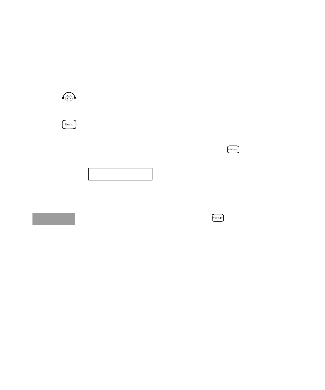
1 Configure the channel.
You must configure a channel before applying performing the adjustment
procedure. Configure the channel to DC VOLTS and 6½ digits.
2 Apply the input signal.
In this example, the input signal is a copper short (see page 69).
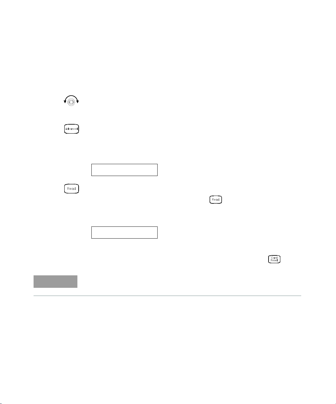
3 Setup the calibration.
The display will show PERFORM CAL.
4 Set the adjustment value.
The display will show the a number. Edit the number to the actual input value.
For the Zero Adjustment, the input value is 0.000000.
+000.000,000 mVDC
5 Begin the adjustment.
The display will show the progress of the adjustment. When all the
adjustments are completed, the display will show done.
DONE
56 Keysight 34970A/34972A Service Guide
Page 57

To Apply Mx+B Scaling to Measurements
The scaling function allows you to apply a gain and offset to all readings on a
specified multiplexer channel during a scan. In addition to setting the gain (“M”)
and offset (“B”) values, you can also specify a custom measurement label for your
scaled readings (RPM, PSI, etc.).
1Configure the channel.
You must configure the channel (function, transducer type, etc.) before
applying any scaling values. If you change the measurement configuration,
scaling is turned off on that channel and the gain and offset values are reset
(M=1 and B=0).
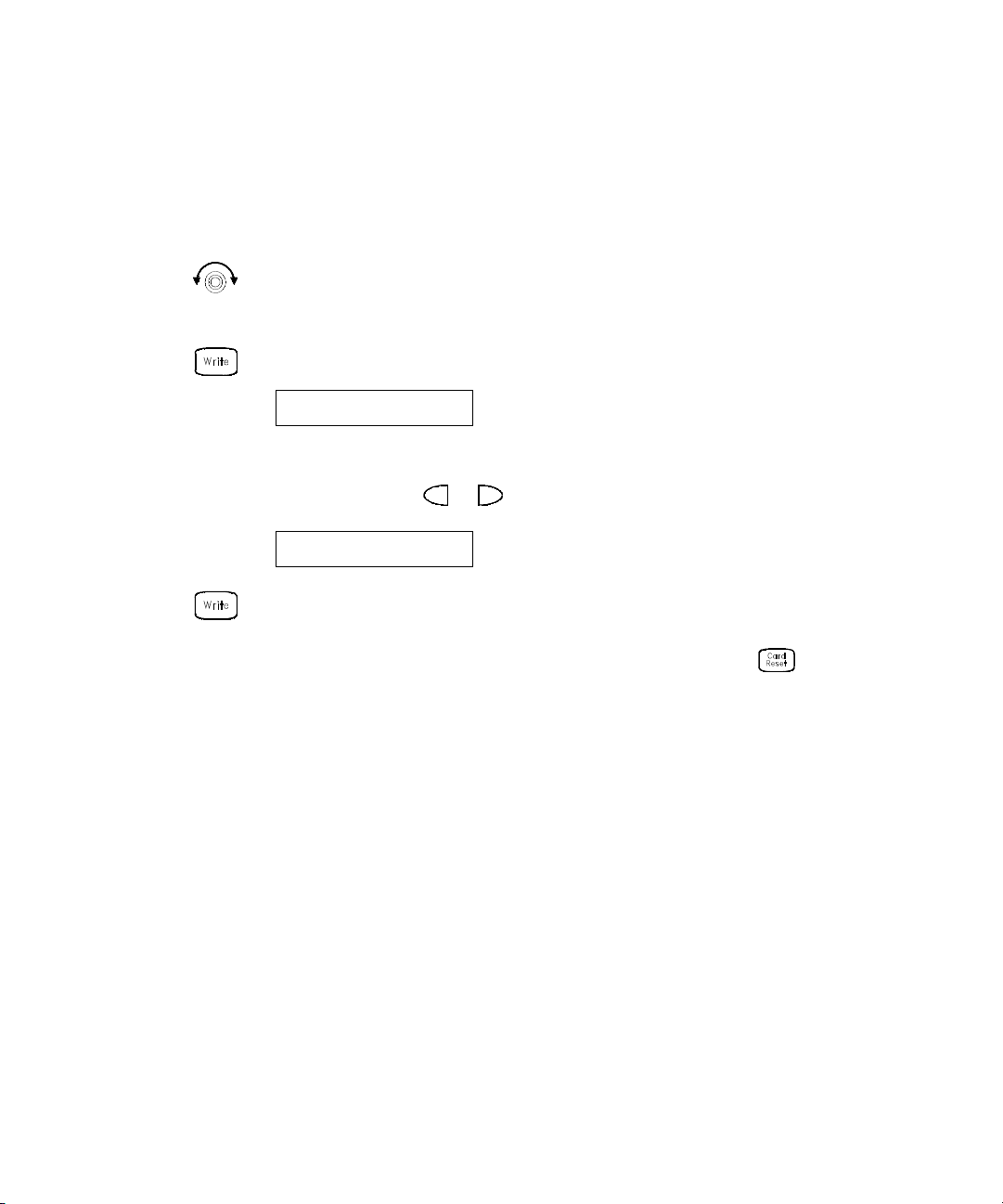
2 Set the gain and offset values.
The scaling values are stored in non-volatile memory for the specified
channels. A Factory Reset turns off scaling and clears the scaling values on all
channels. An Instrument Preset or Card Reset does not clear the scaling values
and does not turn off scaling.
+1.000,000
Set Gain
Front-Panel Overview 3
-0.700,000 OHM
3 Select the custom label.
You can specify an optional three-character label for your scaled readings
(RPM, PSI, etc.). The default label is the standard engineering unit for the
selected function (VDC, OHM, etc.).
LABEL AS OHM
4 Scaling is now applied to the measurements.
Keysight 34970A/34972A Service Guide 57
Set Offset
Page 58

3 Front-Panel Overview
To Read the Relay Cycle Count
The instrument has a Relay Maintenance System to help you predict relay
end-of-life. The instrument counts the cycles on each relay in the instrument and
stores the total count in non-volatile memory on each switch module. You can use
this feature on any of the relay modules and the internal DMM.
– In addition to the channel relays, you can also query the count on backplane
relays and bank relays. Note that you cannot control the state of these relays
from the front panel but you can query the count.
– You can also query the state of the three relays on the internal DMM. These
relays are numbered “1”, “2”, and “3” (which correspond to relays K102, K103,
and K104 respectively). These relays open or close when a function or range is
changed on a module.
– The 34908A multiplexer contains 40 channels which are switched (HI only)
using only 20 relays. Each relay is used to switch HI on two different channels
(and only one channel can be closed at a time). The channels are arranged
such that channels 01 and 21 use different contacts on the same relay. The
remaining channels are also paired in the same manner (channels 02 and 22,
channels 03 and 23, etc.). Therefore, when you query the relay count on a
channel, the number reflects the number of times that the relay was closed.
For example, the relay count will always be the same on channels 01 and 21.
– For more information on relay life and load considerations, refer to “Relay Life
and Preventative Maintenance” in the 34970A/34972A User’s Guide.
– To read the count on the active channel, choose the following item and then
turn the knob. To read the count on the internal DMM relays, turn the knob
counterclockwise beyond the lowest numbered channel in the instrument. To
read the “hidden” relays, turn the knob clockwise beyond the highest
numbered channel in the current slot.
RELAY CYCLES
58 Keysight 34970A/34972A Service Guide
Page 59
To Read a Digital Input Port
NOTE
The multifunction module (34907A) has two non-isolated 8-bit input/output ports
which you can use for reading digital patterns. You can read the live status of the
bits on the port or you can configure a scan to include a digital read.
1 Select the Digital Input port.
Select the slot containing the multifunction module and continue turning the
knob until DIN is displayed (channel 01 or 02).
2 Read the specified port.
You can specify whether you want to use binary or decimal format. Once you
have selected the number base, it is used for all input or output operations on
the same port. To change the number base, press the key and select USE
BINARY or USE DECIMAL.
Front-Panel Overview 3
01010101 DIN
The bit pattern read from the port will be displayed until you press another key,
turn the knob, or until the display times out.
To add a digital input channel to a scan list, press and select the DIO READ
choice.
Binary Display Shown
Keysight 34970A/34972A Service Guide 59
Page 60

3 Front-Panel Overview
To Write to a Digital Output Port
The multifunction module (34907A) has two non-isolated 8-bit
input/output ports which you can use for outputting digital patterns.
1 Select the Digital Output port.
Select the slot containing the multifunction module and continue turning the
knob until DIN is displayed (channel 01 or 02).
2 Enter the bit pattern editor.
Notice that the port is now converted to an output port (DOUT).
00000000 DOUT
3 Edit the bit pattern.
Use the knob and or keys to edit the individual bit values. You can
specify whether you want to use binary or decimal format. Once you have
selected the number base, it is used for all input or output operations on the
same port. To change the number base, press the key and select USE
BINARY or USE DECIMAL.
240 DOUT
4 Output the bit pattern to the specified port.
The specified bit pattern is latched on the specified port. To cancel an output
operation in progress, wait for the display to time out.
Binary Display Shown
Decimal Display Shown
60 Keysight 34970A/34972A Service Guide
Page 61
To Read the Totalizer Count
NOTE
The multifunction module (34907A) has a 26-bit totalizer which can count pulses
at a 100 kHz rate. You can manually read the totalizer count or you can configure
a scan to read the count.
1 Select the totalizer channel.
Select the slot containing the multifunction module and continue turning the
knob until TOTALIZE is displayed (channel 03).
2 Configure the totalize mode.
The internal count starts as soon as you turn on the instrument. You can
configure the totalizer to reset the count to “0” after being read or it can count
continuously and be manually reset.
READ + RESET
3 Read the count.
The count is read once each time you press ; the count does not update
automatically on the display. As configured in this example, the count is
automatically reset to “0” each time you read it.
Front-Panel Overview 3
12345 TOT
The count will be displayed until you press another key, turn the knob, or until
the display times out. To manually reset the totalizer count, press .
To add a totalizer channel to a scan list, press and select the TOT READ choice.
Keysight 34970A/34972A Service Guide 61
Page 62
3 Front-Panel Overview
To Output a DC Voltage
The multifunction module (34907A) has two analog outputs capable of outputting
calibrated voltages between ±12 volts.
1 Select a DAC Output channel.
Select the slot containing the multifunction module and continue turning the
knob until DAC is displayed (channel 04 or 05).
2 Enter the output voltage ed itor.
+00.000 V DAC
3 Set the desired output voltage.
Use the knob and or keys to edit the individual digits.
+05.250VDAC
4 Output the voltage from the selected DAC.
The output voltage will be displayed until you press another key or turn the
knob. To manually reset the output voltage to 0 volts, press .
62 Keysight 34970A/34972A Service Guide
Page 63

Keysight 34970A/34972A Data Acquisition/Switch Unit
Service Guide
4 Calibration Procedures
Calibration Procedures 64
Keysight Technologies Calibration Services 66
Calibration Interval 66
Time Required for Calibration 67
Automating Calibration Procedures 67
Recommended Test Equipment 68
Input Connections 69
Calibration Security 71
Calibration Message 74
Calibration Count 74
Calibration Procedure 75
Aborting a Calibration in Progress 75
Test Considerations 76
Performance Verification Tests 77
Internal DMM Verification Tests 80
Optional AC Performance Verification Tests 87
Internal DMM Adjustments 88
–10 VDC Adjustment Procedure (Optional) 92
Plug-in Module Test Considerations 94
Relay Verification 96
Thermocouple Reference Junction (Optional) 120
34907A Analog Output 123
63
Page 64

4 Calibration Procedures
Calibration Procedures
This chapter contains procedures for verification of the instrument’s performance
and adjustment (calibration). These procedures are required only if the internal
DMM is installed. The chapter is divided into the following sections:
– “Keysight Technologies Calibration Services” on page 4
– “Calibration Interval” on page 4
– “Time Required for Calibration” on page 5
– “Automating Calibration Procedures” on page 5
– “Recommended Test Equipment” on page 6
– “Input Connections” on page 7
– “Calibration Security” on page 9
– “Calibration Message” on page 12
– “Calibration Count” on page 12
– “Calibration Procedure” on page 13
– “Aborting a Calibration in Progress” on page 13
– “Test Considerations” on page 14
– “Performance Verification Tests” on page 15
– “Internal DMM Verification Tests” on page 18
– “Optional AC Performance Verification Tests” on page 25
– “Internal DMM Adjustments” on page 26
– “–10 VDC Adjustment Procedure (Optional)” on page 30
– “Plug-in Module Test Considerations” on page 32
– “Relay Verification” on page 34
– “Thermocouple Reference Junction (Optional)” on page 58
– “34907A Analog Output” on page 61
64 Keysight 34970A/34972A Service Guide
Page 65

Calibration Procedures 4
Closed-Case Electronic Calibration
The instrument features closed-case electronic calibration. No internal
mechanical adjustments are required. The instrument calculates correction
factors based upon the input reference value you set. The new correction factors
are stored in non-volatile memory until the next calibration adjustment is
performed. Non-volatile EEPROM calibration memory does not change when
power has been off or after a remote interface reset.
Keysight 34970A/34972A Service Guide 65
Page 66

4 Calibration Procedures
Keysight Technologies Calibration Services
When your instrument is due for calibration, contact your local Keysight Service
Center for a low-cost recalibration. The 34970A/34972A is supported on
automated calibration systems which allow Keysight to provide this service at
competitive prices.
Calibration Interval
The instrument should be calibrated on a regular interval determined by the
measurement accuracy requirements of your application.
A 1-year interval is adequate for most applications. Accuracy specifications are
warranted only if adjustment is made at regular calibration intervals. Accuracy
specifications are not warranted beyond the 1-year calibration interval. Keysight
does not recommend extending calibration intervals beyond 2 years for any
application.
Adjustment is Recommended
Whatever calibration interval you select, Keysight recommends that complete
re-ad justment should always be performed at the calibration interval. This will
assure that the 34970A/34972A will remain within specification for the next
calibration interval. This criteria for re-adjustment provides the best long-term
stability. Performance data measured using this method can be used to extend
future calibration intervals.
Use the Calibration Count feature (see page 12) to verify that all adjustments have
been performed.
66 Keysight 34970A/34972A Service Guide
Page 67

Time Required for Calibration
The 34970A/34972A can be automatically calibrated under computer control.
With computer control you can perform the complete calibration procedure and
performance verification tests in less than 30 minutes once the instrument is
warmed-up (see “Test Considerations” on page 14). Manual calibrations using the
recommended test equipment will take approximately 2 hours.
Automating Calibration Procedures
You can automate the complete verification and adjustment procedures outlined
in this chapter if you have access to programmable test equipment. You can
program the instrument configurations specified for each test over the remote
interface. You can then enter readback verification data into a test program and
compare the results to the appropriate test limit values.
You can also adjust the instrument from the remote interface. Remote adjustment
is similar to the local front-panel procedure. You can use a computer to perform
the adjustment by first selecting the required function and range. The calibration
value is sent to the instrument and then the calibration is initiated over the remote
interface. The instrument must be unsecured prior to initiating the calibration
procedure.
For further information on programming the instrument, see Chapter 5 in the
34970A/34972A User’s Guide.
Calibration Procedures 4
Keysight 34970A/34972A Service Guide 67
Page 68

4 Calibration Procedures
Recommended Test Equipment
The test equipment recommended for the performance verification and
adjustment procedures is listed below. If the exact instrument is not available,
substitute calibration standards of equivalent accuracy.
A suggested alternate method would be to use the Keysight 3458A 8½digit
Digital Multimeter to measure less accurate yet stable sources. The output value
measured from the source can be entered into the instrument as the target
calibration value.
Application Recommended Equipment Accuracy Requirements
Zero Calibration
DC Voltage
DC Current
Resistance
AC Voltage
AC Current
Frequency
Analog Output 34907A Keysight 34401A <1/5 instrument 24 hour spec
Thermocouple Reference Junction
34901A
34902A
34908A
[a]
[a]
[a]
[a]
[a]
[a]
[a]
Fluke 5700A <1/5 instrument 24 hour spec
Fluke 5700A/5725A <1/5 instrument 24 hour spec
Fluke 5700A <1/5 instrument 24 hour spec
Fluke 5700A/5725A <1/5 instrument 24 hour spec
Fluke 5700A/5725A <1/5 instrument 24 hour spec
Keysight 33220A <1/5 instrument 24 hour spec
Thermistor YSI 44031 (two)
J Type Calibrated Thermocouple Triple
None 4 -terminal all copper short
[b]
±0.1 °C
Point Cell
Relay contact resistance
All switch modules
[a] In addition to the internal DMM, these applications require an input multiplexer module. The Keysight 34901A is recommended.
[b] Thermistor YSI 44031 is available as Keysight part number 34308A (package of five).
Keysight 34401A ±0.001W resolution
68 Keysight 34970A/34972A Service Guide
Page 69

Input Connections
Copper Short
Connections for
DC/AC Current
Connections for
4-wire Ohms
Connections for DC V, AC V,
2- and 4-wire Ohms
34901A
To
Calibrator
You will need an input multiplexer module to verify or adjust the internal DMM.
Input connections can be made using a 34901A
20-Channel Multiplexer.
To use a 34901A to completely verify and adjust the internal DMM, make the
following connections:
Calibration Procedures 4
Keysight 34970A/34972A Service Guide 69
Page 70

4 Calibration Procedures
NOTE
Use shielded twisted pair PTFE insulated cables to reduce settling and noise
errors. Connect the shield to the source LO output.
You can also use a 34902A for test and adjustment of voltage, frequency, and
resistance functions. You cannot test or adjust current inputs with a 34902A. If
you use a 34902A, connect the copper shorts to Channels 7 and 15 and make the
input connections to Channels 8 and 16.
70 Keysight 34970A/34972A Service Guide
Page 71

Calibration Security
NOTE
This feature allows you to enter a security code to prevent accidental or
unauthorized adjustments of the instrument. When you first receive your
instrument, it is secured. Before you can adjust the instrument, you must
unsecure it by entering the correct security code. See page 52 in Chapter 3 for a
procedure to enter the security code.
– The security code is set to “HP034970” or “AT034972”, depending on the
product number, when the instrument is shipped from the factory. The security
code is stored in non-volatile memory, and does not change when power has
been off, after a Factory Reset (*RST command), or after an Instrument Preset
(SYSTem:PRESet command).
– The security code may contain up to 12 alphanumeric characters. The first
character must be a letter, but the remaining characters can be letters,
numbers, or an underscore ( _ ). You do not have to use all 12 characters but
the first character must always be a letter.
If you forget your security code, you can disable the security feature by adding a
jumper inside the instrument as described on the following page.
Calibration Procedures 4
Keysight 34970A/34972A Service Guide 71
Page 72

4 Calibration Procedures
WARNING
WARNING
To Unsecure the Instrument Without the Security Code
To unsecure the instrument without the correct security code, follow the steps
below. A front panel procedure to unsecure the instrument is given on page 52.
See “Electrostatic Discharge (ESD) Precautions” on page 6 before beginning this
procedure.
SHOCK HAZARD. Only service-trained personnel who are aware of the
hazards involved should remove the instrument covers. The procedures in
this section require that you connect the power cord to the instrument with
the covers removed. To avoid electrical shock and personal injury, be
careful not to touch the power-line connections.
1 Disconnect the power cord and all input connections.
2 Remove the instrument cover (see page 16). Turn the instrument over.
3 Apply power and turn on the instrument.
Be careful not to touch the power line connections.
– Exposed Mains
–Do not Touch!
72 Keysight 34970A/34972A Service Guide
Page 73

Calibration Procedures 4
Apply Short
4 Apply a short between the two exposed metal pads marked
CAL UNLOCK as shown in the figure below.
5 While maintaining the short, enter any unsecure code. The instrument is now
unsecured.
6 Remove the short.
7 Turn off the instrument and remove the power cord. Reassemble the
instrument.
Now you can enter a new security code. Be sure to remember the new security
code.
Keysight 34970A/34972A Service Guide 73
Page 74

4 Calibration Procedures
Calibration Message
The instrument allows you to store one message in calibration memory. For
example, you can store such information as the date when the last calibration was
performed, the date when the next calibration is due, the instrument’s serial
number, or even the name and phone number of the person to contact for a new
calibration.
– You can record a calibration message only from the remote interface and only
when the instrument is unsecured. You can read the message from either the
front-panel or over the remote interface. You can read the calibration message
whether the instrument is secured or unsecured.
– The calibration message may contain up to 40 characters. From the front
panel, you can view 13 characters of the message at a time. Press to scroll
through the text of the message. Press again to increase the scrolling
speed.
Calibration Count
You can query the instrument to determine how many calibrations have been
performed. Note that your instrument was calibrated before it left the factory.
When you receive your instrument, be sure to read the count to determine its
initial value.
– The calibration count increments up to a maximum of 65,535 after which it
rolls over to “0”. Since the value increments by one for each calibration point, a
complete calibration may increase the value by many counts.
– The calibration count is also incremented with calibrations of the DAC
channels on the multifunction module.
– Front-Panel Operation:
– Remote Interface Operation:
CALibration:COUNt?
74 Keysight 34970A/34972A Service Guide
CAL COUNT
Page 75

Calibration Procedure
CAUTION
The following procedure is the recommended method to complete an instrument
calibration.
1 Read Test Considerations (page 14).
2 Unsecure the instrument for calibration (page 52).
3 Perform the verification tests to characterize the instrument (incoming data).
4 Perform the zero adjustment procedures.
5 Perform the gain adjustment procedures. Perform the verification tests to
verify the adjustments (outgoing data).
6 Secure the instrument against calibration.
7 Note the new security code and calibration count in the instrument’s
maintenance records.
Aborting a Calibration in Progress
Calibration Procedures 4
Sometimes it may be necessary to abort a calibration after the procedure has
already been initiated. You can abort a calibration at any time by turning off the
power. When performing a calibration from the remote interface, you can abort a
calibration by issuing a remote interface device clear message.
If you abort a calibration in progress when the instrument is attempting to
write new calibration constants to EEPROM, you may lose all calibration
constants for the function. Typically, upon re-applying power, the instrument
will report error 705 Cal:Aborted. You may also generate errors 740 through
746. If this occurs, you should not use the instrument until a complete
re-adjustment has been performed.
Keysight 34970A/34972A Service Guide 75
Page 76

4 Calibration Procedures
Test Considerations
To ensure proper instrument operation, verify that you have selected the correct
power line voltage prior to attempting any procedure in this chapter. See “If the
Instrument Does Not Turn On” on page 41.
Errors may be induced by AC signals present on the input leads during a self-test.
Long test leads can also act as an antenna causing pick-up of AC signals.
For optimum performance, all procedures should comply with the following
recommendations:
– Assure that the calibration ambient temperature is stable and between 18 °C
and 28 °C. Ideally the calibration should be performed at 23 °C ±1 °C.
– Assure ambient relative humidity is less than 80%.
– Allow a 2-hour warm-up period with a copper short connected and the
multiplexer module installed before verification or adjustment.The connections
are shown in the figure on page 7.
– Use shielded twisted pair PTFE insulated cables to reduce settling and noise
errors. Keep the input cables as short as possible.
– Connect the input cable shield to the source LO output.Except where noted in
the procedures, connect the calibrator LO source to earth ground.
Two-wire Ohms measurements are affected by the entire path length, including
the plug-in card trace length and slot trace lengths. On the 34901A, Channel 10 is
recommended as the median path length (on the 34902A, use Channel 8) for
2-wire Ohms verification and adjustments. Install the input multiplexer in slot 200.
Because the instrument is capable of making highly accurate measurements, you
must take special care to ensure that the calibration standards and test
procedures used do not introduce additional errors. Ideally, the standards used to
verify and adjust the instrument should be an order of magnitude more accurate
than each instrument range full scale error specification.
For the DC voltage, DC current, and resistance gain verification measurements,
you should take care to ensure the calibrator’s “0” output is correct. If necessary,
the measurements can be referenced to the calibrator’s “0” output using Mx + B
scaling (see page 57). You will need to set the offset for each range of the
measuring function being verified.
76 Keysight 34970A/34972A Service Guide
Page 77

Performance Verification Tests
Use the Performance verification Tests to verify the measurement performance of
the instrument. The performance verification tests use the instrument’s
specifications listed in Chapter 1, "Specifications" starting on page 29.
You can perform four different levels of performance verification tests:
Self-Test
A series of internal verification tests that give a high confidence that the
instrument is operational.
Quick Verification
A combination of the internal self-tests and selected verification tests.
Performance Verification Tests
An extensive set of tests that are recommended as an acceptance test when you
first receive the instrument or after performing adjustments.
Optional Verification Tests
Calibration Procedures 4
Tests not performed with every calibration. Perform these tests to verify additional
specifications or functions of the instrument.
Keysight 34970A/34972A Service Guide 77
Page 78

4 Calibration Procedures
Self-Test
A brief power-on self-test occurs automatically whenever you turn on the
instrument. This limited test assures that the instrument is capable of operation
and also checks the plug-in cards for basic operation.
To perform a complete self-test hold down the
switch to turn on the instrument; hold down the
seconds until the instrument beeps (a complete description of these tests can be
found in Chapter 6). The instrument will automatically perform the complete
self-test procedure when you release the key. The self-test will complete in
approximately 20 seconds.
– If the self-test is successful, “PASS” is displayed on the front panel.
– If the self-test fails, “FAIL” is displayed and the ERROR annunciator turns on. If
repair is required, see Chapter 6, "Service" for further details.
– If all tests pass, you have a high confidence (~90%) that the instrument is
operational.
key as you press the power
key for more than 5
78 Keysight 34970A/34972A Service Guide
Page 79

Quick Performance Check
The quick performance check is a combination of internal self-test and an
abbreviated performance test (specified by the letter Q in the performance
verification tests). This test provides a simple method to achieve high confidence
in the instrument’s ability to functionally operate and meet specifications. These
tests represent the absolute minimum set of performance checks recommended
following any service activity. Auditing the instrument’s performance for the quick
check points (designated by a Q) verifies performance for “normal” accuracy drift
mechanisms. This test does not check for abnormal component failures.
To perform the quick performance check, do the following:
– Perform a complete self-test. A procedure is given on page 16.
– Perform only the performance verification tests indicated with the letter Q.
If the instrument fails the quick performance check, adjustment or repair is
required.
Performance Verification Tests
The performance verification tests are recommended as acceptance tests when
you first receive the instrument. The acceptance test results should be compared
against the 90 day test limits. You should use the 24-hour test limits only for
verification within 24 hours after performing the adjustment procedure. After
acceptance, you should repeat the performance verification tests at every
calibration interval.
If the instrument fails performance verification, adjustment or repair is required.
Adjustment is recommended at every calibration interval. If adjustment is not
made, you must guard band, using no more than 80% of the specifications listed
in Chapter 1, as the verification limits.
Calibration Procedures 4
Keysight 34970A/34972A Service Guide 79
Page 80

4 Calibration Procedures
Internal DMM Verification Tests
These procedures use inputs connected to a 34901A 20-Channel Multiplexer (see
page 7) installed in slot 200.
Zero Offset Verification
This procedure is used to check the zero offset performance of the internal DMM.
Verification checks are only performed for those functions and ranges with unique
offset calibration constants. Measurements are checked for each function and
range as described in the procedure below.
Zero Offset Verification Procedure
1 Make sure you have read “Test Considerations” on page 14.
2 This procedure will measure the shorts installed on Channels 209 and 219.
Leave the Amps input connections (Channel 221) open.
3 Select each function and range in the order shown in the table below. Before
executing each test, you must press to enable reading monitoring on the
selected channel (or use the ROUTe:MON command from the remote interface).
Compare measurement results to the appropriate test limits shown in the table
(see page 17).
Input
Open
Open
Open
Channel 221
Function
DC Current
Quick
[b]
Range 24 hour 90 day 1 year
10 mA
100 mA
1A
Check
Q
[a]
± 60 mA
± 1 mA
± 4 mA
Error from Nominal
± 2 mA
± 5 mA
± 100 mA
± 2 mA
± 5 mA
± 100 mA
80 Keysight 34970A/34972A Service Guide
Page 81

Calibration Procedures 4
NOTE
Input
Short
Short
Short
Short
Short
Short
Short
Short
Short
Short
Short
Short
[a] Q: Quick performance verification test points.
[b] Select 6½ digit resolution.
[c] For 2-wire ohms, an additional 4W of error must be added.
Function
DC Volts
2-Wire
Ohms
and
4-Wire
Ohms
[b]
Range 24 hour 90 day 1 year
100 mV
1V
10V
100V
300V
100 W
1 kW
[c]
10 kW
100 kW
1 MW
10 MW
100 MW
Channel 209
Quick
Check
Q
Q
[a]
± 3.5 mV
± 40 mV
± 600 mV
± 3.5 mW
± 50 mW
± 500 mW
± 100 W
± 10 kW
± 6 mV
± 6 mV
± 6 mW
± 10 W
Error from Nominal
± 4 mV
± 7 mV
± 50 mV
± 600 mV
± 9 mV
± 4 mW
± 10 mW
± 100 mW
± 1 W
± 10 W
± 100 W
± 10 kW
± 4 mV
± 7 mV
± 50 mV
± 600 mV
± 9 mV
± 4 mW
± 10 mW
± 100 mW
± 1 W
± 10 W
± 100 W
± 10 kW
Zero offset calibration using a mul tifunction calibrator is NOT recommended.
The calibrator and cabling offset can be large and unstable causing poor offset
calibration of the internal DMM.
Keysight 34970A/34972A Service Guide 81
Page 82

4 Calibration Procedures
Gain Verification
This procedure is used to check the “full scale” reading accuracy of the internal
DMM. Verification checks are performed only for those functions and ranges with
unique gain calibration constants. Begin verification by selecting a measuring
function and range. Make sure you have read “Test Considerations” on page 14.
DC VOLTS, Resistance, and DC CURRENT Gain Verification Test
1 Make sure you have read “Test Considerations” on page 14.
2 Select each function and range in the order shown below. Before executing
each test, you must press to enable reading monitoring on the selected
channel (or use the ROUTe:MON command from the remote interface).
3 Compare measurement results to the appropriate test limits shown in the
table. (Be certain to allow for appropriate source settling.)
Input
-10 V
100 mV
1V
10V
100V
300V
100 W
1 kW
10 kW
100 kW
1 MW
10 MW
100 MW
[c]
Channel 210
Function
DC Volts
2-Wire
Ohms
and
4-Wire
Ohms
± 30 W
Error from Nominal
± 250 mV
± 8 mV
± 37 mV
± 250 mV
± 4.1 mV
± 19.5 mV
± 12 mW
± 90 mW
± 900 mW
± 9 W
± 90 W
± 2.1 kW
± 810 kW
± 400 mV
± 9 mV
± 47 mV
± 400 mV
± 5.1 mV
± 22.5 mV
± 14 mW
± 110 mW
± 1.1 W
± 11 W
± 110 W
± 4.1 kW
± 810 kW
Quick
[b]
Range 24 hour 90 day 1 year
10V
100 mV
1V
10V
100V
300V
100 W
1 kW
[d]
10 kW
100 kW
1 MW
10 MW
100 MW
Check
Q
Q
Q
Q
[a]
± 190 mV
± 6.5 mV
± 26 mV
± 190 mV
± 2.6 mV
± 12 mV
± 6.5 mW
± 26 mW
± 250 mW
± 2.5 W
± 1.6 kW
±310 kW
82 Keysight 34970A/34972A Service Guide
Page 83

Calibration Procedures 4
Input
10 mA
100 mA
1 A
[a] Q: Quick performance verification test points.
[b] Select 6½ digit resolution.
[c] Verify only, no adjustment required.
[d] The 2-wire ohms resistance verification test is optional (see note on page 27). For 2-wire ohms, an additional 1 W
of error must be added (see page 29). Add a 1-second channel delay when using Fluke 5700 in 2-wire
compensated mode. This avoids response time issues with 2-wire compensation when 34970A/34972A’s current
source contains a pulse.
Function
DC Current
[b]
Range 24 hour 90 day 1 year
10 mA
100 mA
1A
Channel 209
Quick
Check
Q
[a]
± 1.5 mA
± 14 mA
± 560 mA
Error from Nominal
± 5 mA
± 35 mA
± 900 mA
± 7 mA
± 55 mA
± 1.1 mA
Keysight 34970A/34972A Service Guide 83
Page 84

4 Calibration Procedures
AC VOLTS Gain Verification Test
Configuration: AC Volts
LF 3 HZ:SLOW (in the Advanced menu)
1 Make sure you have read “Test Considerations” on page 14.
2 Select Channel 210, set the AC VOLTS function and the 3 Hz input filter. With
the slow filter selected, each measurement takes 7 seconds to complete.
Before executing each test, you must press to enable reading monitoring
on the selected channel (or use the ROUTe:MON command from the remote
interface).
3 Select each range in the order shown below. Compare measurement results to
the appropriate test limits shown in the table. (Be certain to allow for
appropriate source settling.)
Input
V rms Frequency 24 hour 90 day 1 year
100 mV
100 mV
1 V
1 V
10 V
10 V
10 V
[b]
10 mV
100 V
100 V
300 V
[c]
300 V
[a] Q: Quick performance verification test points.
[b] For this test, isolate the calibrator’s output from earth ground.
[c] Some calibrators may have difficulty driving the internal DMM and cable load at this V-Hz output. Use short, low
capacitance cable to reduce calibration loading. Verification can be performed at >195 Vrms. New test limits can
be computed from the accuracy specification shown in Chapter 1 for the actual test conditions used.
1 kHz
50 kHz
1 kHz
50 kHz
1 kHz
50 kHz
10 Hz
1 kHz
1 kHz
50 kHz
1 kHz
50 kHz
Range
100 mV
1 V
10 V
100 mV
100 V
300V
Quick
Check
Q
Q
Q
[a]
± 70 mV
± 150 mV
± 700 mV
± 1.5 mV
± 15 mV
± 34 mV
± 70 mV
± 150 mV
± 270 mV
± 600 mV
± 7 mV
± 7 mV
Error from Nominal
± 90 mV
± 160 mV
± 900 mV
± 1.6 mV
± 9 mV
± 16 mV
± 9 mV
± 45 mV
± 90 mV
± 160 mV
± 390 mV
± 690 mV
± 100 mV
± 170 mV
± 1 mV
± 1.7 mV
± 10 mV
± 17 mV
± 10 mV
± 46 mV
± 100 mV
± 170 mV
± 420 mV
± 720 mV
84 Keysight 34970A/34972A Service Guide
Page 85

Calibration Procedures 4
NOTE
The 50 kHz AC voltage test points may fail performance verification if the
internal shields have been removed and reinstalled. See “Gain Adjustment” on
page 27, for further information on how to recalibrate the AC voltage function.
AC CURRENT Gain Verification Test
Configuration: AC Current
LF 3 HZ:SLOW (in the Advanced menu)
1 Make sure you have read “Test Considerations” on page 14.
2 Select Channel 221, set the AC CURRENT function and the 3 Hz input filter.
With the slow filter selected, each measurement takes 7 seconds to complete.
Before executing each test, you must press to enable reading monitoring
on the selected channel (or use the ROUTe:MON command from the remote
interface).
3 Select each range in the order shown below. Compare measurement results to
the appropriate test limits shown in the table. (Be certain to allow for
appropriate source settling.)
Input
Current Frequency 24 hour 90 day 1 year
[b]
10 mA
[b]
100 mA
10 mA
[b]
1 A
[a] Q: Quick performance verification test points.
[b] Verify only, no adjustment.
1 kHz
1 kHz
1 kHz
1 kHz
Range
10 mA
100 mA
1 A
1 A
Quick
Check
Q
[a]
± 14 mA
± 600 mA
± 1.41 mA
± 1.4 mA
Error from Nominal
± 14 mA
± 600 mA
± 1.41 mA
± 1.4 mA
± 14 mA
± 600 mA
± 1.41 mA
± 1.4 mA
Keysight 34970A/34972A Service Guide 85
Page 86

4 Calibration Procedures
Frequency Gain Verification Test
Configuration: Frequency
6½ digits
1 Make sure you have read “Test Considerations” on page 14.
2 Select Channel 210, select the FREQUENCY function and set 6½ digits.
3 Select each range in the order shown below. Compare measurement results to
the appropriate test limits shown in the table. (Be certain to allow for
appropriate source settling.)
Input
Voltage Frequency 24 hour 90 day 1 year
[b]
10 mV
1 V
[a] Q: Quick performance verification test points.
[b] Verify only, no adjustment. For this test, isolate the calibrator’s output from earth ground.
100 Hz
100 kHz
Range
100 mV
1 V Q
Quick
Check
[a]
± 0.06 Hz
Error from Nominal
± 6 Hz
± 0.1 Hz
± 10 Hz
± 0.1 Hz
± 10 Hz
86 Keysight 34970A/34972A Service Guide
Page 87

Optional AC Performance Verification Tests
These tests are not intended to be performed with every calibration. They are
provided as an aid for verifying additional instrument specifications. There are no
adjustments for these tests; they are provided for performance verification only.
Configuration: AC Volts
LF 3 HZ:SLOW (in the Advanced menu)
1 Make sure you have read “Test Considerations” on page 14.
2 Select Channel 210, select the AC Volts function and the 3 HZ filter. Before
executing each test, you must press to enable reading monitoring on the
selected channel (or use the ROUTe:MON command from the remote interface).
3 Select each range in the order shown below. Compare measurement results to
the appropriate test limits shown in the table. (Be certain to allow for
appropriate source settling.)
Calibration Procedures 4
Input
Voltage Frequency 24 hour 90 day 1 year
1 V
1 V
1 V
1 V
1 V
1 V
10 V
1 V
100 mV
20 Hz
20 kHz
100 kHz
200 kHz
250 kHz
300 kHz
1 kHz
1 kHz
1 kHz
Range
1 V
1 V
1 V
1 V
1 V
1 V
10 V
10 V
10 V
± 700 mV
± 700 mV
± 6.3 mV
± 45 mV
± 45 mV
± 45 mV
± 7 mV
± 3.4 mV
± 13 mV
Error from Nominal
± 900 mV
± 900 mV
± 6.8 mV
± 45 mV
± 45 mV
± 45 mV
± 9 mV
± 4.5 mV
± 14 mV
± 1 mV
± 1 mV
± 6.8 mV
± 45 mV
± 45 mV
± 45 mV
± 10 mV
± 4.6 mV
± 14.06 mV
Keysight 34970A/34972A Service Guide 87
Page 88

4 Calibration Procedures
NOTE
Internal DMM Adjustments
You will need a 34901A 20-Channel Multiplexer to perform the following
procedures (see page 7). Install the Multiplexer in slot 200.
Zero Adjustment
Each time you perform a zero adjustment, the Internal DMM stores a new set of
offset correction constants for every measurement function and range. The
Internal DMM will sequence through all required functions and ranges
automatically and store new zero offset calibration constants. All offset
corrections are determined automatically. You may not correct a single range or
function without re-entering ALL zero offset correction constants automatically.
This feature is intended to save calibration time and improve zero calibration
consistency.
Never turn off the Internal DMM during Zero Adjustment.This may cause ALL
calibration memory to be lost.
Zero Adjustment Procedure
The zero adjustment procedure takes about 5 minutes to complete. Be sure to
allow the instrument to warm up for 2 hours before performing the adjustments.
Follow the steps outlined below. Review “Test Considerations” on page 14 before
beginning this test. Also see page 56, for an example of how to initiate a zero
calibration.
1 This procedure will use the copper shorts installed on Channels 209 and 219.
Leave the Amps input connections (Channel 221) open.
2 Select Channel 209. Select the DC VOLTS function.
3 Press
adjustment procedure.
4 Use the knob and arrow keys to set the number in the display to 0.000000 and
press .
5 Perform the Zero Offset Verification tests (see page 18) to check zero
calibration results.
88 Keysight 34970A/34972A Service Guide
to enter the calibration menu. Press
again to begin the
Page 89

Gain Adjustment
NOTE
The Internal DMM stores a single new gain correction constant each time this
procedure is followed. The gain constant is computed from the calibration value
entered for the calibration command and from measurements made automatically
during the adjustment procedure.
Most measuring functions and ranges have gain adjustment procedures. Only the
100 MW range does not have gain calibration procedures. The gain calibration
value may be entered through the front panel menu or over the remote interface.
See page 56, for an example of how to enter calibration values.
Adjustments for each function should be performed ONLY in the order shown in
the performance verification table. See “Performance Verification Tests” earlier in
this chapter for the tables used for gain adjustments.
Gain Adjustment Considerations
– The zero adjustment procedure must have been recently performed prior to
beginning any gain adjustment procedures.
– The optional –10 VDC adjustment should be performed only after servicing the
Internal DMM’s a-to-d converter or after replacing network A4U101 or
calibration RAM A4U505.
Calibration Procedures 4
– When performing a 4-wire ohms gain adjustment, a new gain correction
constant is also stored for the corresponding 2-wire ohms measurement
range. If desired, the 2-wire gain can be adjusted separately after the 4-wire
ohms gain calibration is completed.
– During the AC voltage gain adjustments, some of the DC voltage gain
constants are used. Perform the DC voltage gain calibration before the AC
voltage gain calibration.
Never turn off the instrument during a Gain Adjustment. This may cause
calibration memory for the present function to be lost.
Keysight 34970A/34972A Service Guide 89
Page 90

4 Calibration Procedures
Valid Gain Adjustment Input Values
Gain adjustment can be accomplished using the following input values.
Function Range Val id Cal ibration Input Values
DC VOLTS
100 mV to 100 V
300 V
0.9 to 1.1 x Full Scale
250 V to 303 V
OHMS, OHMS 4W
DC CURRENT
AC VOLTS
[a]
100W to 10 MW
10 mA to 1 A
10 mV to 100 V
300 V
AC CURRENT
Frequency
[a] Valid frequencies are as follows: 1 kHz ± 10% for the 1 kHz calibration,
45 kHz - 100 kHz for the 50 kHz calibration,
and 10 Hz ± 10% for the 10 Hz calibration.
1 A
Any
0.9 to 1.1 x Full Scale
0.9 to 1.1 x Full Scale
0.9 to 1.1 x Full Scale
95 V to 303 V
9 mA to 11 mA
Any Input >100 mV rms,
1 kHz - 100 kHz
90 Keysight 34970A/34972A Service Guide
Page 91
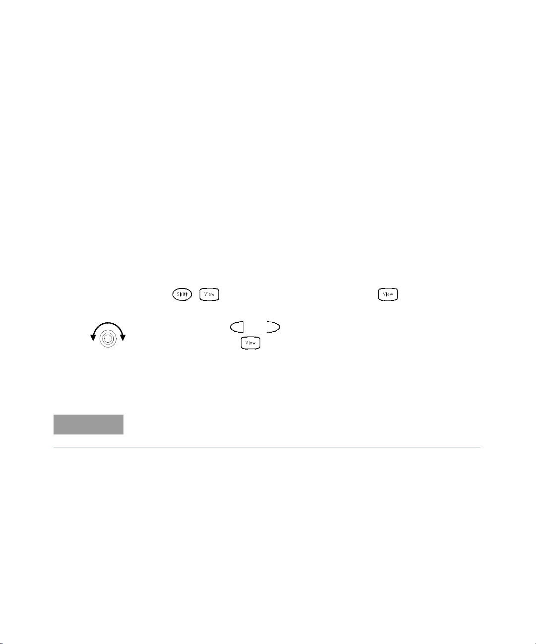
Calibration Procedures 4
NOTE
Gain Adjustment Procedure
Adjustment for each function should be performed only in the order shown in the
performance verification table. The performance verification tables used for gain
adjustments start on page 20.
Review the Test Considerations (page 14) and Gain Adjustment (page 27) sections
before beginning this test.
Configuration: DC functions — 6½ digits
AC functions — LF 3 HZ:SLOW (in the Advanced menu)
1 Select Channel 210. Configure the channel to each function and range shown
in the gain verification tables (pages 18 – 79).
2 Apply the input signal shown in the “Input” column of the appropriate
verification table.
3 Note: Always complete tests in the same order as shown in the appropriate
verification table.
4 Press
to enter the calibration menu. Press
adjustment procedure.
5 Use the knob, and and to set the number in the display to the actual
input value and press .
again to begin the
6 Perform the appropriate Gain Verification Test to check the calibration results.
7 Repeat steps 1 through 6 for each gain verification test point shown in the
tables.
Each range in the gain adjustment procedure takes less than
20 seconds to complete.
Keysight 34970A/34972A Service Guide 91
Page 92

4 Calibration Procedures
–10 VDC Adjustment Procedure (Optional)
The –10 VDC calibration electronically enhances the Internal DMM’s
a-to-d converter linearity characteristic. This adjustment should ONLY be
performed after servicing the A-to-D converter or replacement of the calibration
RAM.
You will need a 34901A 20-Channel Multiplexer to perform the following
procedures (see page 7). Install the Multiplexer in slot 200.
1 If a zero calibration has not been performed recently, perform one before
beginning this procedure (see page 26).
2 Select Channel 210. Configure the channel as follows:
DC VOLTS
10 V range
6½ digits
INTEG 100 PLC (in the Advanced menu)
INPUT R > 10 G (in the Advanced menu)
Before executing each test, you must press to enable reading monitoring
on the selected channel (or use the ROUTe:MON command from the remote
interface).
3 Measure and note the voltage offset present at the end of the measurement
cable by shorting the ends of the Channel 210 measurement cable. Be sure to
use a copper wire and allow enough time for the residual thermal offset to
stabilize (usually about 1 minute).
4 Connect the input cable to the calibrator output and set the calibrator to
output +10V. Allow enough settling time for any thermal offset voltages to
stabilize (usually about 1 minute).
5 Perform a +10V DC gain calibration. Press
menu. Press
92 Keysight 34970A/34972A Service Guide
again to begin the adjustment procedure.
to enter the calibration
Page 93
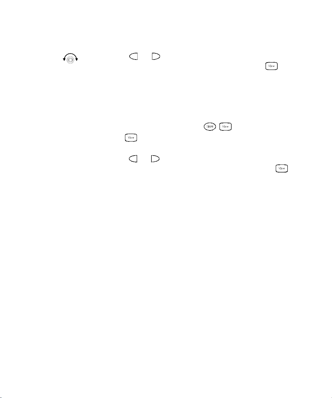
Calibration Procedures 4
6 Use the knob, and to set the number in the display to the sum of the
calibrator output and the measured offset (from step 3) and press . For
example, if the calibrator output is 10.001 volts and the measured offset is 10
µV, enter +10.001010 volts. When the adjustment finishes, verify that new
readings fall within ± 20 µV of the calibrator output plus the offset.
7 Reverse the cable connections to the calibrator to create a -10 VDC voltage
standard. You must physically reverse the cables. DO NOT switch the output
polarity of the calibrator.
8 Perform a –10V DC gain calibration. Press
menu. Press
again to begin the adjustment procedure. Be sure to allow
to enter the calibration
time for thermal offsets to stabilize (usually about 1 minute).
9 Use the knob, and to set the number in the display to the difference of
the calibrator output and the measured offset (from step 3) and press .
Using the previous example values, enter 10 µV minus 10.001 volts or
–10.000990 volts.
10 When the adjustment finishes, verify that new readings fall within ± 30 µV of
the calibrator output minus the offset.
Keysight 34970A/34972A Service Guide 93
Page 94

4 Calibration Procedures
WARNING
WARNING
Plug-in Module Test Considerations
For optimum performance, all test procedures should comply with the following
recommendations:
– Assure that the calibration ambient temperature is stable and between 18 °C
and 28 °C. Ideally the calibration should be performed at 23 °C ± 1 °C.
– Assure ambient relative humidity is less than 80%.
– Install the plug-in module and allow a 45 minute warm-up period before
verification or adjustment.
– Use shielded twisted pair PTFE insulated cables to reduce settling and noise
errors. Keep the input cables as short as possible.
– Remove all user wiring and connections from the plug-in modules before
verification or adjustment.
– Use 4-wire Ohms measurement techniques for checking relay contact
resistance. Check directly at the terminals where possible.
TO PREVENT ELECTRICAL SHOCK
To prevent electrical shock, use only wire that is rated for the highest voltage
to any channel. Before removing a module cover, turn off all power to
external devices connected to the module.
CAUTION WITH MULTIPLE SIGNALS
To avoid the possibility of multiple signal sources becoming connected
together, we recommend when multiplexing two or more sources they
should be connected on separate modules or on separate banks of the same
module.
94 Keysight 34970A/34972A Service Guide
Page 95

Calibration Procedures 4
WARNING
WARNING
CAUTION WITH HAZARDOUS VOLTAGES
When any channel is connected to a hazardous voltage source, all channels
in the module should be treated as hazardous and all channel wiring in the
module should be rated for the maximum voltage applied. Thermocouples
attached to any other channel on the module should have insulation rated
for the maximum voltage, or have additional insulation added rated for the
maximum voltage and should be isolated from conductive parts using a
thermal compound or tape rated for the maximum voltage applied. Do not
mount, move, or remove any thermocouples when the device under test is
connected to a supply source.
ENVIRONMENTAL HEALTH AND SAFETY
When any channel is connected to a hazardous voltage source, the
instrument and the device under test should be supervised, following local
EHS practices to restrict access.
Keysight 34970A/34972A Service Guide 95
Page 96

4 Calibration Procedures
Relay Verification
There are two methods you can use to verify relays:
– Read the relay cycle count.
– Measure the relay contact resistance.
Relay Cycle Count
The instrument has a Relay Maintenance System to help you predict relay
end-of-life. The instrument counts the cycles on each relay in the instrument and
stores the total count in non-volatile memory on each switch module. You can use
this feature on any of the relay modules and the internal DMM.
– In addition to the channel relays, you can also query the count on backplane
relays and bank relays. Note that you cannot control the state of these relays
from the front panel but you can query the count.
– You can also query the state of the three relays on the internal DMM. These
relays are numbered “1”, “2”, and “3” (which correspond to relays K102, K103,
and K104 respectively). These relays open or close when a function or range is
changed on a module.
– The 34908A multiplexer contains 40 channels which are switched (HI only)
using only 20 relays. Each relay is used to switch HI on two different channels
(and only one channel can be closed at a time). The channels are arranged
such that channels 01 and 21 use different contacts on the same relay. The
remaining channels are also paired in the same manner (Channels 02 and 22,
Channels 03 and 23, etc.). Therefore, when you query the relay count on a
channel, the number reflects the number of times that the relay was closed.
For example, the relay count will always be the same on Channels 01 and 21.
– You can reset the count (allowed only from remote) but the instrument must be
unsecured (see “To Unsecure for Calibration” on page 52 to unsecure the
instrument).
– For more information on relay life and load considerations, refer to “Relay Life
and Preventative Maintenance” in Chapter 8 of the 34970A/34972A User’s
Guide.
– A procedure to read the relay cycle count is given on page 58.
96 Keysight 34970A/34972A Service Guide
Page 97

Calibration Procedures 4
NOTE
NOTE
NOTE
(Optional) 34901A Relay Contact Resistance Verification
This optional procedure uses an external DMM to make 4-wire ohms
measurements across the relay contacts on the 34901A. The measured resistance
is the series resistance of the two relay contacts (both contacts are in the same
relay).
Be sure to read “Plug-in Module Test Considerations” on page 32.
Tests 1 - 5:
See the diagram on page 36 for the required connections for each test (be sure to
probe the components at the indicated location). For these measurements, the
34901A is not installed in the 34970A/34972A. Record the 4-wire ohms
measurements from the external DMM in the table below.
The connections to the external DMM are different for each of Tests 1, 2, 4, and
5. Be sure to verify the connections shown in the table below for each of the four
tests.
Test #
1 L401 J101, C14 L401 J101, C14 _____________ Ohms
2 L402 J101, C15 L402 J101, C15 _____________ Ohms
3 Add (Test 1 + Test 2) _____________ Ohms
4 F501 C21 I F501 C21 I _____________ Ohms
5 F502 C22 I F502 C22 I _____________ Ohms
Connect bare copper wires (approximately 3 cm in length) to the I terminals of
Channels 21 and 22 as shown below. These wires will be used to make shorts
across the channels in Tests 6 through 39.
Keysight 34970A/34972A Service Guide 97
External DMM Ohmmeter Connections
Measured Value
HI LO HI Sense LO Sense
Page 98

4 Calibration Procedures
Probe here
for L402
measurement.
Probe here for F501 measurement.
Probe here for F502 measurement.
Note: Be sure to probe the components at
the indicated locations on the module.
Connections for 34901A Verification Tests 1 through 5
98 Keysight 34970A/34972A Service Guide
Page 99

Calibration Procedures 4
Channel 20 should be left open.
Tests 6 - 8:
Make the connections to the 34901A as shown in the diagram below. Be sure to
route your wiring for proper strain relief and install the module cover. Install the
34901A in slot 200 of the 34970A/34972A. Open all channels on the module by
performing a Factory Reset (press
again and select “Factory Reset”). Configure Channel 20 as follows: DC volts, 10
volt range, and 5½ digits.
and select “Recall State”; press
Connections for 34901A Verification Tests 6 through 39
Keysight 34970A/34972A Service Guide 99
Page 100

4 Calibration Procedures
Enable reading monitoring by pressing on the selected channel (or use the
ROUTe:MON command). Record the 4-wire ohms measurements from the external
DMM in the following table.
Test #
6 Ch 20 P2 P2 P1 P1 ________Ohms 2.00 W K421
7 Ch 20 P2 P2 P3 P3 ________Ohms — —
8 Subtract (Test 7 - Test 6) ________Ohms 2.00 W K422
Channel
Configured
External DMM Ohmmeter Connections
HI LO HI Sense LO Sense
Measured Value
Test
Limit
Relay Measured
Tests 9 - 10:
Open all channels on the module by performing a Factory Reset. Configure
Channel 10 (module in slot 200) as follows: 4-wire ohms, 1 kW range, and 5½
digits.
Enable reading monitoring by pressing on the selected channel (or use the
ROUTe:MON command). Record the 4-wire ohms measurements from the external
DMM in the following table.
Test #
9 Ch 10 P2 P2 P3 P3 ________Ohms — —
10 Subtract (Test 9 - Test 3) ________Ohms 2.00 W K423
Channel
Configured
External DMM Ohmmeter Connections
HI LO HI Sense LO Sense
Measured Value
Test
Limit
Relay Measured
100 Keysight 34970A/34972A Service Guide
 Loading...