

Page 1

User’s Guide
Test Equipment Depot - 800.517.8431 - 99 Washington Street Melrose, MA 02176 - TestEquipmentDepot.com
Publication Number 33220-90002 (order as 33220-90100 manual set)
Edition 4, May 2007
Copyright © 2003, 2005, 2007 Agilent Technologies, Inc.
Agilent 33220A
20 MHz Function/
Arbitrary Waveform Generator
Page 2

Agilent 33220A at a Glance
The Agilent Technologies 33220A is a 20 MHz synthesized function
generator with built-in arbitrary waveform and pulse capabilities.
Its combination of bench-top and system features makes this function
generator a versatile solution for your testing requirements now and in
the future.
Convenient bench-top features
• 10 standard waveforms
• Built-in 14-bit 50 MSa/s arbitrary waveform capability
• Precise pulse waveform capabilities with adjustable edge time
• LCD display provides numeric and graphical views
• Easy-to-use knob and numeric keypad
• Instrument state storage with user-defined names
• Portable, ruggedized case with non-skid feet
Flexible system features
• Four downloadable 64K-point arbitrary waveform memories
• GPIB (IEEE-488), USB, and LAN remote interfaces are standard
• LXI Class C Compliant
• SCPI (Standard Commands for Programmable Instruments) compatibility
Note:
Unless otherwise indicated, this manual applies to all Serial
2
Numbers.
Page 3

The Front Panel at a Glance
1 Graph Mode/Local Key
2 On/Off Switch
3 Modulation/Sweep/Burst Keys
4 State Storage Menu Key
5 Utility Menu Key
6 Help Menu Key
7 Menu Operation Softkeys
8 Waveform Selection Keys
9 Manual Trigger Key (used for
Sweep and Burst only)
10 Output Enable/Disable Key
11
Knob
12
Cursor Keys
13
Sync Connector
14
Output Connector
Note: To get context-sensitive help on any front-panel key or menu softkey,
press and hold down that key.
3
Page 4

The Front-Panel Display at a Glance
Menu Mode
Numeric
Readout
Mode
Information
Trigger
Information
Softkey Labels
Units
Output
Status
Graph Mode
To enter or exit the Graph Mode, press the key.
Parameter
Name
Parameter
Value
Display
Icon
Signal
Ground
In Graph Mode, only one parameter label
is displayed for each key at one time.
4
Page 5

Front-Panel Number Entry
1. Use the keys below the knob to move the cursor left or right.
1. Key in a value as you would on a typical calculator.
You can enter numbers from the front-panel using one of two methods.
Use the knob and cursor keys to modify the displayed number.
2. Rotate the knob to change a digit (clockwise to increase).
Use the keypad to enter numbers and the softkeys to select units.
2. Select a unit to enter the value.
5
Page 6

The Rear Panel at a Glance
1
External 10 MHz Reference Input Terminal
(Option 001 only)
2
Internal 10 MHz Reference Output Terminal
(Option 001 only)
3 External Modulation Input Terminal
Input: External Trig/FSK/Burst Gate
4
Output: Trigger Output
.
.
5 USB Interface Connector
6 LAN Interface Connector
7 GPIB Interface Connector
8 Chassis Ground
Use the menu to:
• Select the GPIB address (see chapter 2).
• Set the network parameters for the LAN interface (see chapter 2).
• Display the current network parameters (see chapter 2).
Note: The External and Internal 10 MHz Reference Terminals (1 and 2,
above) are present only if Option 001, External Timebase Reference, is
installed. Otherwise, the holes for these connectors are plugged.
WARNING For protection from electrical shock, the power cord ground must not be
defeated. If only a two-contact electrical outlet is available, connect the
instrument’s chassis ground screw (see above) to a good earth ground.
6
Page 7

In This Book
Quick Start Chapter 1 prepares the function generator for use and
helps you get familiar with a few of its front-panel features.
Front-Panel Menu Operation Chapter 2 introduces you to the frontpanel menu and describes some of the function generator’s menu features.
Features and Functions Chapter 3 gives a detailed description of the
function generator’s capabilities and o peration. You will find t his chapter
useful whether you are operating the function generator from the front
panel or over the remote interface.
Remote Interface Reference
to help you program the function generator over the remote interface.
Error Messages Chapter 5 lists the error messages that may appear
as you are working with the function generator. Each listing contains
information to help you diagnose and solve the problem.
Application Programs Chapter 6 contains several remote interface
application programs to help you develop programs for your application.
Tutorial Chapter 7 discusses the fundamentals of signal generation
and modulation techni ques.
Specifications Chapter 8 lists the function generator’s specifications.
Chapter 4 contains reference information
7
Page 8

You can contact Agilent Technologies at one of the following telephone
numbers for warranty, service, or technical support information.
In the United States: (800) 829-4444
In Europe: 31 20 547 2111
In Japan: 0120-421-345
Or use our Web link for information on contacting Agilent worldwide.
8
Page 9

Contents
Chapter 1 Quick Start 13
To Prepare the Function Generator for Use 15
To Adjust the Carrying Handle 16
To Set the Output Frequency 17
To Set the Output Amplitude 18
To Set a DC Offset Voltage 20
To Set the High-Level and Low-Level Values 21
To Select “DC Volts” 22
To Set the Duty Cycle of a Square Wave 23
To Configure a Pulse Waveform 24
To View a Waveform Graph 25
To Output a Stored Arbitrary Waveform 26
To Use the Built-In Help System 27
To Rack Mount the Function Generator 29
Chapter 2 Front-Panel Menu Operation 31
Front-Panel Menu Reference 33
To Select the Output Termination 35
To Reset the Function Generator 35
To Output a Modulated Waveform 36
To Output an FSK Waveform 38
To Output a PWM Waveform 40
To Output a Frequency Sweep 42
To Output a Burst Waveform 44
To Trigger a Sweep or Burst 46
To Store the I nstrument State 47
To Configure the Remote Int erface 48
Chapter 3 Features and Functions 53
Output Configuration 55
Pulse Waveforms 70
Amplitude Modulation (AM) 74
Frequency Modulation (FM) 79
Phase Modulation (PM) 85
Frequency-Shift Keying (FSK) Modulation 89
Pulse Width Modulation (PWM) 93
Frequency Sweep 99
Burst Mode 106
Contents
9
Page 10

Contents
Contents
Triggering 115
Arbitrary Waveforms 120
System-Related Operations 126
Remote Interface Configuration 135
External Timebase Reference (Option 001) 144
Calibration Overview 146
Factory Defa ul t Sett in gs 150
Chapter 4 Remote Interface Reference 153
SCPI Command Summary 155
Simplified Programming Overview 168
Using the APPLy Command 170
Output Configuration Commands 179
Pulse Configuration Commands 192
Amplitude Modulation (AM) Commands 197
Frequency Modulation (FM) Commands 200
Phase Modulation (PM) Commands 204
Frequency-Shift Keying (FSK) Commands 207
Pulse Width Modulation (P WM) Commands 210
Frequency Sweep Commands 215
Burst Mode Commands 223
Triggering Commands 231
Arbitrary Waveform Commands 234
State Storage Commands 245
System-Related Commands 249
Interface Configuration Commands 254
Phase-Lock Commands (Option 001 Only) 258
The SCPI Status System 260
Status Reporting Commands 270
Calibration Commands 274
An Introduction to the SCPI Language 276
Using Device Clear 281
10
Page 11

Contents
Chapter 5 Error Messages 283
Command Errors 285
Execution Errors 288
Device Dependent Errors 303
Query Errors 304
Instrument Errors 305
Self-Test Errors 306
Calibration Errors 308
Arbitrary Waveform Errors 309
Chapter 6 Application Programs 311
Introduction 312
Program Listings 314
Chapter 7 Tutorial 321
Direct Digital Synthesis 323
Creating Arbitrary Waveforms 326
Square Waveform Generation 328
Pulse Waveform Generation 329
Signal Imperfections 330
Output Amplitude Control 332
Ground Loops 333
Attributes of AC Signals 335
Modulation 337
Frequency Sweep 342
Burst 343
Contents
11
Page 12

Chapter 8 Specifications 345
Waveforms 346
Waveform Characteristics 346
Common Characteristics 347
Modulation 347
Sweep 348
Burst 348
Trigger Characteristics 348
Programming Times 348
General 349
Product Dimensions 350
Index 351
Contents
12
Page 13

1
1
Quick Start
Page 14

1
Quick Start
One of the first things yo u will want to do w ith your function ge nerator is
to become acquainted with the fron t panel. W e have written the exercises
in this chapter to prepare the instrument for use and help you get
familiar with some of its front-panel operations. This chapter is divided
into the following sections:
• To Prepare the Function Generator for Use, on page 15
• To Adjust the Carrying Handle, on page 16
• To Set the Output Frequency, on page 17
• To Set the Output Amplitude, on page 18
• To Set a DC Offset Voltage, on page 20
• To Set the High-Level and Low-Level V alues, on page 21
• To Select “DC Volts”, on page 22
• To Set the Duty Cycle of a Square Wave, on page 23
• To Configure a Pulse Waveform, on page 24
• To View a Waveform Graph, on page 25
• To Output a Stored Arbitrary Waveform, on page 26
• To Use the Built-In Help System, on page 27
• To Rack Mount the Function Generator, on page 29
14
Page 15

Chapter 1 Quick Start
To Prepare the Function Generator for Use
To Prepare the Function Generator for Use
1 Check the list of supplied items.
Verify that you have received the following items with your instrument.
If anything is missing, please contact your nearest Agilent Sales Office.
1
Power
Switch
• Power cord (for country of destination).
• Certificate of Calibration.
• Agilent 33220A Product Reference CD (product software,
programming examples, and manuals).
• Agilent Automation-Ready CD (Agilent IO Libraries Suite).
• USB 2.0 cable.
2 C onnect the power cord and turn on the function generator.
The instrument runs a short power-on self test, which takes a few
seconds. When the instrument is ready for use it displays a message
about how to obtain help, along with the current GPIB address and
USB identification string. The function generator powers up in the sine
wave function at 1 kHz with an amplitude of 100 mV peak-to-peak (into
a 50Ω termination).
enable the Output
If the function generator does not turn on, verify that the power cord is
firmly connected to the power receptacle on the rear p a ne l (t he po w er -line
voltage is automatically sensed at power-on). You should also make sure
that the function generator is connected to a power source that is energized
Then, verify that the function generator is turned on.
At power-on, the
connector, press the key
Output
connecto r
.
is disabled. To
4
.
If the power-on self test fails, “Self-Test Failed” is displayed along with an
error code. See the Agilent 33220A Service Guide for information on
error codes, and for
Agilent for service.
instructions on returning the function generator to
15
Page 16

1
Chapter 1 Quick Start
To Adjust the Carrying Handle
To Adjust the Carrying Handle
To adjust the position, grasp the handle by the sides and pull outward.
Then, rotate the handle to the desired position.
Retracted
Carrying
Position
Extended
16
Page 17

Chapter 1 Quick Start
To Set the Output Frequency
To Set the Output Frequency
At power-on, the function generator outputs a sine wave at 1 kHz with
an amplitude of 100 mV peak-to-peak (into a 50Ω termination).
The following steps show you how to change the frequency to 1.2 MHz.
1
1Press the “Freq” softkey.
The displayed frequency is either the power-on value or the frequency
previously selected. When you change functions, the same frequency is
used if the present value is valid for the new function. To set the
waveform period instead, press the Freq softkey again to toggle to the
Period softkey (the current selection is highlighted).
2 Enter the magnitude of the desired frequency.
Using the numeric keypad, enter the value “1.2”.
3 Select the desired units.
Press the softkey that corresponds to the desired units. When you select
the units, the function generator outputs a waveform with the displayed
frequency (if the output is enabled). For this example, press MHz
.
4
Note: Y
keys.
ou can also enter the desired value using the knob and cursor
17
Page 18

1
Chapter 1 Quick Start
To Set the Output Amplitude
To Set the Output Amplitude
At power-on, the function generator outputs a sine wave with an
amplitude of 100 mV peak-to-peak (into a 50Ω termination).
The following steps show you how to change the amplitude to 50 mVrms.
1Press the “Ampl” softkey.
The displayed amplitude is either the power-on value or the amplitude
previously selected. When you change functions, the same amplitude is
used if the present value is valid for the new function. To set the amplitude
using a high level and low level, press the Ampl softkey again to toggle to
the HiLevel and LoLevel softkeys (the current selection is highlighted).
2 Enter the magnitude of the desired amplitude.
Using the numeric keypad, enter the value “50”.
3 Select the desired units.
Press the softkey that corresponds to the desired units. When you select
the units, the functio n ge ner ator out puts the wave form w ith the disp layed
amplitude (if the output is enabled). For this example, press mV
Note: Y
keys.
18
ou can also enter the desired value using the knob and cursor
RMS
.
Page 19

Chapter 1 Quick Start
To Set the Output Amplitude
You can easily convert the displayed amplitude from one unit to another.
For example, the following steps show you how to convert the amplitude
from Vrms to Vpp.
4 Enter the numeric entry mode.
Press the key to enter the numeric entry mode.
5 Select the new units.
Press the softkey that corresponds to the desired units. The displayed
value is converted to the new units. For this example, press the Vpp
softkey to convert 50 mVrms to its equivalent in volts peak-to-peak.
1
4
To change the displayed amplitude by decades, press the right-cursor
key to move the cursor to the units on the right side of the display.
Then, rotate the knob to increase or decrease the displayed amplitude
by decades.
19
Page 20

1
Chapter 1 Quick Start
To Set a DC Offset Voltage
To Set a DC Offset Voltage
At power-on, the function generator outputs a sine wave with a dc offset
of 0 volts (into a 50Ω termination). The following steps show you how to
change the offset to –1.5 mVdc.
1Press the “Offset” softkey.
The displayed off set voltage is either the power-on value or the offset
previously selected. When you change functions, the same offset is used
if the present value is valid for the new function.
2 Enter the magnitude of the desired offset.
Using the numeric keypad, enter the value “–1.5”.
3 Select the desired units.
Press the softkey that corresponds to the desired units. When you select
the units, the functio n ge ner ator out puts the wave form w ith the disp layed
offset (if the output is enabled). For this example, press mV
Note: Y
keys.
20
ou can also enter the desired value using the knob and cursor
DC
.
Page 21

Chapter 1 Quick Start
To Set the High-Level and Low-Level Values
To Set the High-Level and Lo w-Level Values
You can specify a signal by setting its amplitude and dc offset values, as
described previously. Another way to set the limits of a signal is to
specify its high-level (maximum) and low-level (minimum) values. This
is typically convenient for digital applications. In the following example,
let's set the high-level to 1.0 V and the low-level to 0.0 V.
1 Press the "Ampl" softkey to select "Ampl".
2 Press the softkey again to toggle to "HiLevel".
Note that both the Ampl and Offset softkeys toggle together, to HiLevel
and LoLevel, respectively.
1
4
3 Set the "HiLevel" value.
Using the numeric keypad or the knob, select a value of "1.0 V". (If you
are using the keypad, you will need to select the unit, "V", to enter the
value.)
4 Press the "LoLevel" softkey and set the value.
Again, use the numeric keyp ad or the knob to enter a value of "0.0 V".
Note that these settings (high-level = "1.0 V" and low-level = "0.0 V") are
equivalent to setting an amplitude of "1.0 Vpp" and an offset of "500
mVdc".
21
Page 22

1
Chapter 1 Quick Start
To Select “DC Volts”
To Select “DC Volts”
You can select the "DC Volts" feature from the “Utility” menu, and then
set a constant dc voltage as an "Offset" value. Let's set "DC Volts" = 1.0
Vdc.
1 Press and then select the DC On softkey.
The Offset value becomes selected.
2 Enter the desired voltage level as an "Offset".
Enter 1.0 Vdc with the numeric keypad or knob.
You can enter any dc voltage from -5 Vdc to +5 Vdc.
22
Page 23
Chapter 1 Quick Start
To Set the Duty Cycle of a Square Wave
To Set the Duty Cycle of a Square Wave
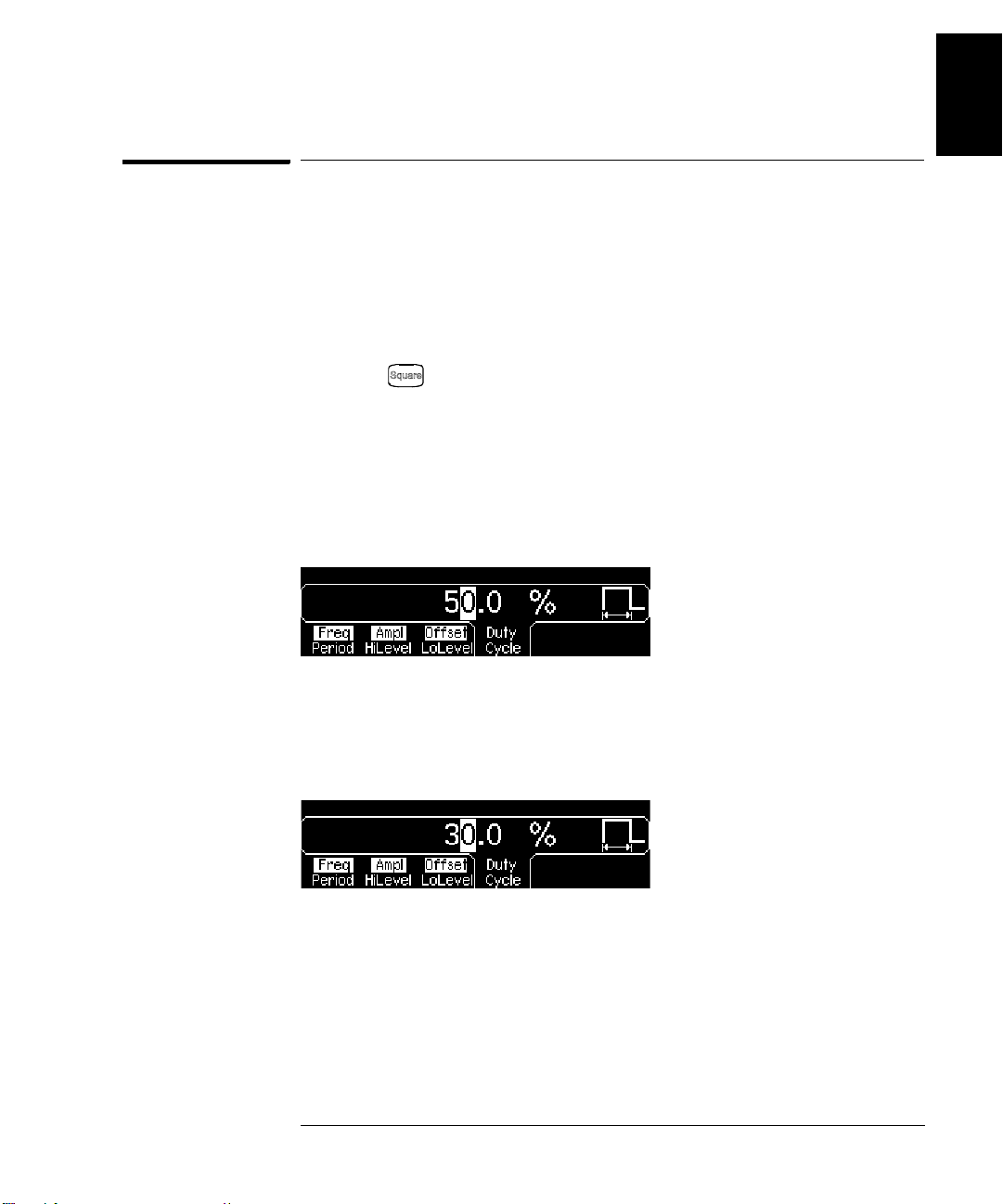
At power-on, the duty cycle for square waves is 50%. You ca n adjust the
duty cycle from 20% to 80% for output frequencies up to 10 MHz. The
following steps show you how to change the duty cycle to 30%.
1
1 Select the square wave function.
Press the key and then set the d esired output frequency to any
value up to 10 MHz.
2Press the “Duty Cycle” softkey.
The displayed duty cycle is either the power-on value or the percentage
previously selected. Th e duty cycle represents the amount of time per
cycle that the square wave is at a high level (note the icon on the right
side of the display).
3 Enter the desired duty cycle.
Using the numeric keypad or the knob, select a duty cycle value of “30”.
The function generator adjusts the duty cy cle immediately and outputs a
square wave with the specified value (if the output is enabled).
4
23
Page 24

1
Chapter 1 Quick Start
To Configure a Pulse Waveform
To Configure a Pulse Waveform
You can configure the function generator to output a pulse waveform
with variable pulse width and edge time. The following steps show you
how to configure a 500 ms pulse waveform with a pulse width of 10 ms
and edge times of 50 ns.
1 Select the pulse function.
Press the key to select the pulse function and output a pulse
waveform with the default parameters.
2 Set the pulse period.
Press the Period softkey and then set the pulse period to 500 ms.
3 Set the pulse width.
Press the Width softkey and then set the pulse width to 10 ms. The pulse
width represents the time from the 50% threshold of the rising edge to
the 50% threshold of the next falling edge (note the display icon).
4 Set the edge time for both edges.
Press the Edge Time softkey and then set the edge time for both the
rising and falling edges to 50 ns. The edge time represents the time from
the 10% threshold to the 90% threshold of each edge (note the display icon
24
).
Page 25

Chapter 1 Quick Start
To View a Waveform Graph
To View a Waveform Graph
In the Graph Mode, you can view a graphical representation of the
current waveform parameters. The softkeys are listed in the same order
as in the normal display mode, and they perform the same functions.
However, only one label (for example, Freq or Period) is displayed for
each softkey at one time.
1 Enable th e Graph Mode.
1
4
Press the key to enable the Graph Mode. The na me of the
selected
parameter’s numeric value field are both highlighted.
2 Select the desired paramet er.
To select a specific parameter, note the softkey labels at the bottom of
the display.
• As in the normal disp lay mode , you can e dit numb ers using either the
•
• To exit the Graph Mode, press again.
parameter,
For example
numeric keypad or the knob and cursor keys.
Param ete rs w h ic h n o rmally tog g le when you p re ss a key a seco nd t im e
also toggle in the Graph Mode. Howev er, you can see on ly on e label
for each softkey at one time (for example, Freq or Period).
The key also serves as a key to restore front-panel control
after remote interface operations.
shown in the up per-left corne r of the display, a nd the
, to select period, press the Period softkey.
currently
25
Page 26
1
Chapter 1 Quick Start
To Output a Stored Arbitrary Waveform
To Output a Stored Arbitrary Waveform
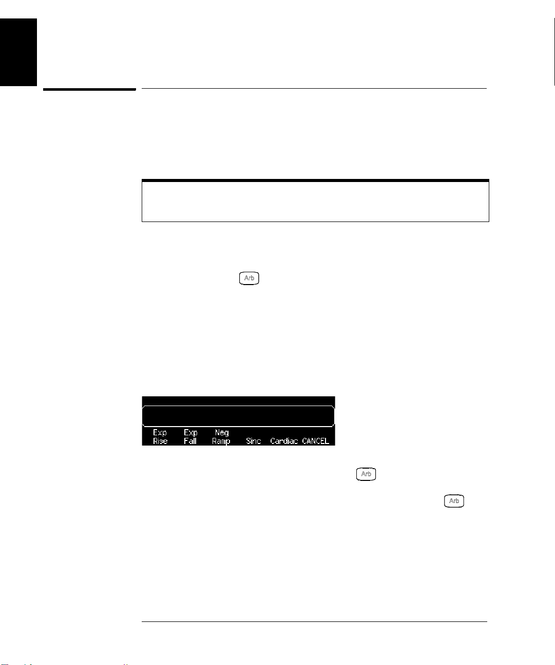
There are five built-in arbitrary waveforms stored in non-volatile memory
The following steps show you how to output the built-in “exponential fall”
waveform
For information on creating a custom arbitrary waveform, refer to
“To Create and Store an Arbitrary Waveform” on page 120.
1 Select the arbitrary waveform function.
When you press the key to select the arbitrary waveform function,
a temporary message is displayed indicating which waveform is currently
selected (the default is “exponential rise”).
2 Select the active waveform.
Press the Select Wform softkey and then press the Built-In softkey to
select from the five built-in waveforms. Then press the Exp Fall softkey.
The waveform is output using the present settings for frequency,
amplitude, and offset unless you change them.
from the front panel.
.
The selected waveform is now assigned to the key. Whenever you
press this key, the selected arbitrary waveform is output. To quickly
determine which arbitrary waveform is currently selected, press .
26
Page 27

Chapter 1 Quick Start
To Use the Built-In Help System
To Use the Built-In Help System
The built-in help system is designed to provide context-sensitive
assistance on any front-panel key or menu softkey. A list of help topics
is also available to assist you with several front-panel operations.
1
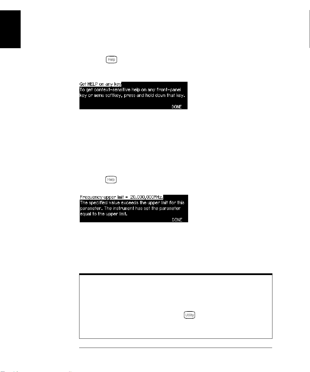
1 View the help information for a function key.
Press and hold down the key. If th e message contains
information than will fit on the di spla y, pre s s th e ↓ softkey or turn the
knob clockwise to view the remaining information.
Press DONE to exit Help.
2 View the help information for a menu softkey.
Press and hold down the Freq softkey.
information than will fit on the di spla y, pre s s th e ↓ softkey or rotate the
knob clockwise to view the remaining information.
Press DONE to exit Help.
If the message con tai ns
more
more
4
27
Page 28
1
Chapter 1 Quick Start
To Use the Built-In Help System
3 View the list of help topics.
Press the key to view the li st of available help topics. To scroll
through the list, press the ↑ or ↓ softkey or rotate the knob. Sele ct the
third topic “Get HELP on any key” and then press SELECT.
Press DONE to exit Help.
4 View the help information for displayed messages.
Whenever a limit is exceeded or an y other invali d config uration i s found,
the function generator will display a message. For example, if you enter
a value that exceeds the frequency limit for the selected function,
a message will be displayed. The built-in help system provides additional
information on the most recent message to be displayed.
Press the k ey, select the first top ic “
and then press SELECT.
Press DONE to exit Help.
Local Language Help: The built-in help system in available in multiple
languages. All messages, context-sensitive help, and help topics appear
in the selected language. The menu softkey labels and status line
messages are not translated.
To select the local language, press the key, press the System
softkey, and then press the Help In softkey. Select the desired
language.
View the last message displayed”,
28
Page 29

Chapter 1 Quick Start
To Rack Mount the Function Generator
To Rack Mount the Function Generator
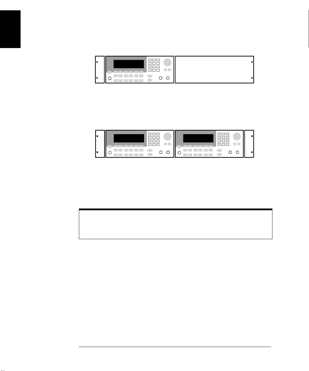
You can mount the Agilent 33220A in a standard 19-inch rack cabinet
using one of two optional kits available. Instructions and mounting
hardware are included with each rack-mounting kit. Any Agilent
System II instrument of the same size can be rack-mounted beside the
Agilent 33220A.
Note:
before rack-mounting the instrument.
Remove the carrying handle, and the front and rear rub ber bumpers
4
1
,
To remove the handle, rotate it to vertical and pull the ends outward.
Front
To remove the rubber bumper, stretch a corner and then slide it off.
Rear (bottom view)
29
Page 30
1
Chapter 1 Quick Start
To Rack Mount the Function Generator
To rack mount a single instrument, order adapter kit 5063-9240.
To rack mount two instruments side-by-side, order lock-link kit 5061- 8769
and flange kit 5063-9212. Be sure to use the support rails in the rack cabinet.
In order to prevent overheating, do not block the flow of air into or out of
the instrument. Be sure to allow enough clearance at the rear, sides, and
bottom of the instrument to permit adequate internal air flow.
30
Page 31

2
2
Front-Panel Menu Operation
Page 32

Front-Panel Menu Operation
This chapter introduces you t o the fro nt-pane l keys and menu oper ation.
This chapter does not give a deta iled descri ption of eve ry front-pa nel key
or menu operation. It does, however, give you an overview of the frontpanel menus and many front-panel operations. See chapter 3 “Features
and Functions,” starting on page 53, for a complete discussion of the
function generator’s capabilities and operation.
2
• Front-Panel Menu Reference, on page 33
• To Select the Output Termination, on page 35
• To Reset the Function Generator, on page 35
•To Output a Modulated Waveform, on page 36
• To Output an FSK Waveform, on page 38
•To Output a PWM Waveform, on page 40
• To Output a Frequency Sweep, on page 42
• To Output a Burst Waveform, on page 44
• To Trigger a Sweep or Burst, on page 46
• To Store the Instrument State, on page 47
• To Configure the Remote Interface, on page 48
32
Page 33

Chapter 2 Front-Panel Menu Operation
Front-Panel Menu Reference
Front-Panel Menu Reference
This section gives an overview of the front-panel menus. The remainder
of this chapter contains examples of using the front-panel menus.
2
Configure the modulation parameters for AM, FM, PM, FSK and PWM.
• Select the modulation type.
• Select an internal or external modulation source.
• Specify AM modulation depth, modulating frequency, and modulation shape.
Specify FM frequency deviation, modulating frequency, and modulation shape.
•
•
Specify PM phase deviation, modulating frequency, and modulation shape.
• Specify FSK “hop” frequency and FSK rate.
• Specify PWM deviation, modulating frequency, and modulation shape.
Configure the parameters for frequency sweep.
• Select linear or logarithmic sweeping.
• Select the start/stop frequencies or
• Select the time in seconds required to complete a sweep.
• Specify a marker frequency.
• Specify an internal or external trigger source for the sweep.
• Specify the slope (rising or falling edge) for an external trigger source.
• Specify the slope (rising or falling edge) of the “Trig Out” signal.
Configure the parameters for burst.
center/ span frequencies.
4
• Select the triggered (N Cycle) or externally-gated burst mode.
• Select the number of cycles per burst (1 to 50,000, or Infinite).
• Select the starting phase angle of the burst (-360° to +360°).
• Specify the time from the start of one burst to the start of the next burst.
• Specify an internal or external trigger source for the burst.
• Specify the slope (rising or falling edge) for an external trigger source.
• Specify the slope (rising or falling edge) of the “Trig Out” signal.
33
Page 34

2
Chapter 2 Front-Panel Menu Operation
Front-Panel Menu Reference
Store and recall instrument states.
• Store up to four instrument states in non-volatile memory.
• Assign a custom name to each storage location.
• Recall stored instrument states.
• Restore all instrument settings to their factory default values.
• Select the instrument’s power-on configuration (last or factory default).
Configure system-related parameters.
• Generate a dc-only voltage level.
• Enable/disable the Sync signal which is output from the “Sync” connector.
• Select the output termination (1Ω to 10 kΩ, or Infinite).
• Enable/disable amplitude autoranging.
• Select the waveform polarity (normal or inverted).
• Select the GPIB address.
• Specify the LAN configuration (IP address and network configuration).
Select how periods and commas are used in numbers displayed on the front panel.
•
• Select the local language for front-panel messages and help text.
• Enable/disable the tone heard when an error is generated.
• Enable/disable the display bulb-saver mode.
• Adjust the contrast setting of the front-panel display.
• Perform an instrument self-test.
• Secure/unsecure the instrument for calibration and perform manual calibrations.
• Query the instrument’s firmware revision codes.
View the list of Help topics.
• View the last message displayed.
• View the remote command error queue.
• Get HELP on any key.
• How to generate a dc-only voltage level.
• How to generate a modulated waveform.
• How to create an arbitrary waveform.
• How to reset the instrument to its default state.
• How to view a waveform in the Graph Mode.
• How to synchronize multiple instruments.
• How to obtain Agilent Technical Support.
34
Page 35

Chapter 2 Front-Panel Menu Operation
To Select the Output Termination
To Select the Output Termination
The Agilent 33220A has a fixed series output impedance of 50 ohms to
the front-panel Output connector. If the actual load impedance is
different than the value specified, the displayed amplitude and offset
levels will be incorrect. The load impedance setting is simply provided
as a convenience to ensure that the displayed voltage matches the
expected load.
1Press .
2 Navigate the menu to set the output termination.
Press the Output Setup softkey and then select the Load softkey.
2
4
3 Select the desired output termination.
Use the knob or numeric keypad to select the desired load impedance or
press the Load softkey again to choose “High Z”.
To Reset the Function Generator
To reset the instrument to its factory default state, press and then
select the Set to Defaults softkey. Press YES to confirm the operation.
For a complete listing of the instrument’s power-on and reset conditions,
see “Agilent 33220A Factory Default Settings” on page 151.
35
Page 36

2
Chapter 2 Front-Panel Menu Operation
To Output a Modulated Waveform
To Output a Modulated Waveform
A modulated waveform consists of a carrier and a modulating waveform.
In AM (amplitude modulation), the amplitude of the carrier is varied by
the amplitude of the modulating waveform. For this example, you will
output an AM waveform with 80% modulation depth. The carrier will
be a 5 kHz sine wave and the modulating waveform will be a 200 Hz
sine wave.
1 Select the function, frequency, and amplitude of the carrier.
Press and then press the Freq, Ampl, and Offset softkeys to
configure the carrier waveform.
with an amplitude of 5 Vpp.
2 Select AM.
Press and then select “AM” using the Type softkey. Notice that
a status message “AM by Sine” is shown in the upper-left corner of
the display.
3 Set the modulation depth.
Press the AM Depth softkey and then set the value to 80% using the
numeric keypad or the knob and cursor keys.
36
For this example, select a 5 kHz sine wave
Page 37

Chapter 2 Front-Panel Menu Operation
To Output a Modulated Waveform
4 Set the modu lating frequency.
Press the AM Freq softkey and then set the value to 200 Hz usi ng the
numeric keypad or the knob and cursor keys.
5 Select the modulating waveform shape.
Press the Shape softkey to select the shape of the modulating waveform.
For this example, select a sine wave.
At this point, the function generator outputs an AM waveform with the
specified modulation parameters (if the output is enabled).
6 View the waveform.
2
4
Press t
To turn off the Graph Mode, press
o view the waveform parameters.
again
.
37
Page 38

2
Chapter 2 Front-Panel Menu Operation
To Output an FSK Waveform
To Output an FSK Waveform
You can configure the function generator to “shift ” its output frequency
between two preset values using FSK modul ati on. The ra te at which the
output shifts between the tw o freq uencies (cal led the “ca rrier freq ue ncy”
and the “hop frequency”) is determined by the internal rate generator or
the signal level on the rear-panel Trig In connector. For this example,
you will set the “carrier” frequency to 3 kHz and the “hop” frequency to
500 Hz, with an FSK rate of 100 Hz.
1 Select the function, frequency, and amplitude of the carrier.
Press and then press the Freq, Ampl, and Offset softkeys to
configure the carrier waveform.
with an amplitude of 5 Vpp.
2 Select FSK.
Press and then select “FSK” using the Ty pe softkey. Notice that a
status message “FSK” is shown in the upper-left corner of the display.
38
For this example, select a 3 kHz sine wave
Page 39

Chapter 2 Front-Panel Menu Operation
To Output an FSK Waveform
3 Set the “hop” frequency.
Press the Hop Freq softkey and then set the value to 500 Hz using the
numeric keypad or the knob and cursor keys.
4 Set the FSK “shift” rate.
Press the FSK Rate softkey and then set the value to 100 Hz using the
numeric keypad or the knob and cursor keys.
At this point, the function generator outputs an FSK waveform (if the
output is enabled).
2
4
5 View the waveform.
Press t
To turn off the Graph Mode, press
o view the waveform parameters.
again
.
39
Page 40

2
Chapter 2 Front-Panel Menu Operation
To Output a PWM Waveform
To Output a PWM Waveform
You can configure the function generator to output a pul se wi dth
modulated (PWM) waveform. The Agilent 33220A provides PWM for
pulse carrier waveforms, and PWM is the only type of modulation
supported for pulse waveforms. In PWM, the pulse wi dth or duty cycle of
the carrier waveform is varied according to the modulating waveform.
You can specify either a pulse wi dth and widt h deviat ion, or a pulse duty
cycle and duty cycle deviation, the deviation to be controlled by the
modulating waveform.
For this example, you will specify a pulse width and pulse width
deviation for a 1 kHz pulse waveform with a 100 Hz sine wave
modulating waveform.
1 Select the carrier waveform parameters.
Press and then press the Freq, Ampl, Offset, Width, and Edge
Time softkeys to configure the carrier waveform. For this example, select
a 1 kHz pulse waveform with an amplitude of 1 Vpp, a zero offset, a pulse
width of 100 µs, and an edge time of 50 ns.
2 Select PWM.
Press (PWM is the only modulatio n typ e for Pulse). Notice that a
status message "PWM by Sine" is shown in the upper-left corner of the
display.
3 Set the width deviation.
Press the Width Dev softkey and set the va lue to 20 µs using the numeric
keypad or the knob and cursor keys.
40
Page 41

Chapter 2 Front-Panel Menu Operation
To Output a PWM Waveform
4 Set the modu lating frequency.
Press the PWM Freq softkey and then set the value to 5 Hz using the
numeric keypad or the knob and cursor keys.
5 Select the modulating waveform shape.
Press the Shape softkey to select the shape of the modulating waveform.
For this example, select a sine wave.
At this point, the function generator outputs a PWM waveform with the
specified modulation parameters (if the output is enabled).
6 View the waveform.
Press to view the waveform and paramet ers.
2
4
To turn off the Graph Mode, press again.
Of course, to really view the PWM wavef orm, you would need to ou tput it
to an oscilloscope. If you do this, you will see how the pulse width varies,
in this case, from 80 to 120 µs. At a modulation frequency of 5 Hz, the
deviation is quite visible.
41
Page 42

2
Chapter 2 Front-Panel Menu Operation
To Output a Frequency Sweep
To Output a Frequency Sweep
In the frequency sweep mode, the function generator “steps” from the
start frequency to the stop frequency at a sweep rate which you specify.
You can sweep up or down in frequency, and with either linear or
logarithmic spacing. For this example, you will output a swept sine wave
from 50 Hz to 5 kHz. You will not change the other parameters from their
default settings: internal sweep trigger, linear spacing, and 1 second
sweep time.
1 Select the function and amplitude for the sweep.
For sweeps, you can select sine, square, ramp, or arbitrary waveforms
(pulse, noise, and dc are not allowed) . For this example, select a sine wave
with an amplitude of 5 Vpp.
2 Select the sweep mode.
Press and then verify that the linear sweep mode is currently
selected. Notice that a status message “Linear Sweep” is shown in the
upper-left corner of the display.
3 Set the start frequency.
Press the Start softkey and then set the value to 50 Hz using the numeric
keypad or the knob and cursor keys.
42
Page 43

Chapter 2 Front-Panel Menu Operation
To Output a Frequency Sweep
4 Set the stop frequency.
Press the Stop softkey and then set the value to 5 kHz using the numeric
keypad or the knob and cursor keys.
2
At this point, the function generator outputs a continuous sweep from
50 Hz to 5 kHz (if the output is enabled).
Note: If desired, you can set the frequency boundaries of the sweep
using a center frequency and frequency span. These parameters are
similar to the start frequency and stop frequency and are included to
give you added flexibility. To achieve the same results, set the center
frequency to 2.525 kHz and the frequency span to 4.950 kHz.
5 View the waveform.
Press t
To turn off the Graph Mode, press
You can generate a single frequency sweep by pressing the key.
For more information, see “To Trigger a Sweep or Burst” on page 46.
o view the waveform parameters.
again
.
4
43
Page 44

2
Chapter 2 Front-Panel Menu Operation
To Output a Burst Waveform
To Output a Burst Waveform
You can configure the function generator to output a waveform with a
specified number of cycles, called a burst. You can output the burst at a
rate determined by the internal rate generator or the signal level on the
rear-panel Trig In connector. For this example, you will output a
three-cycle sine wave with a 20 ms burst period. You will not change the
other parameters from their default settings: internal burst source and
0 degree starting phase.
1 Select the function and amplitude for the burst.
For burst waveforms, you can select sine, square, ramp, pulse, or
arbitrary waveforms (noise is allowed only in the “gated” burst mode
and dc is not allowed). For this example, select a sine wave with an
amplitude of 5 Vpp.
2 Select the burs t mode.
Press and then verify that the “N Cycle” (inte rnally-triggered) mode
is currently selected. Notice that a status message “N Cycle Burst” is
shown in the upper-left corner of the display.
44
Page 45

Chapter 2 Front-Panel Menu Operation
To Output a Burst Waveform
3 Set the burst count.
Press the # Cycles softkey and then set the count to “3” u sing the
numeric keypad or knob.
4 Set the burst period.
Press the Burst Period softkey and then set the period to 20 ms using the
numeric keypad or the knob an d cursor keys. The burst period sets the
time from the start of one burst to the start of the next burst (note the
display icon).
2
4
At this point, the function generator outputs a continuous three-cycle burst
(if the output is enabled).
5 View the waveform.
Press t
To turn off the Graph Mode, press
You can generate a single burst (with the specified count) by pressing
the key. For more information, see “To Trigger a Sweep or Burst”
on page 46.
You can also use an external gate signal to either turn the burst signal
“on” or “off” based on the external signal applied to the rear-panel
Tri g In connector. For more information, see “Burst Mode” on page 106.
o view the waveform parameters.
again
.
45
Page 46

2
Chapter 2 Front-Panel Menu Operation
To Trigger a Sweep or Burst
To Trigger a Sweep or Burst
You can issue triggers from the front pa nel for sweeps and b ursts using a
manual trigger or an internal trigger.
• Internal or “automatic” triggering is enabled with the default settings
of the function generator. In this mode, the function generator
outputs continuously when the sweep or burst mode is selected.
• Manual triggering init iates one sweep o r outp uts one b urst each ti me
you press the key from the front-panel. Continue pressing this
key to re-trigger the function generator.
• The key is disabled when in remote (the remote icon turns on
while in remote) and when a function other than sweep or burst is
currently selected (or when the output is disabled). The key
flashes off momentarily when us ing a manual trigger.
46
Page 47

Chapter 2 Front-Panel Menu Operation
To Store the Instrument State
To Store the Instrument State
You can store the instrument state in one of four non-volatile storage
locations. A fifth storage location automatically holds the power-down
configuration of the instrument. When power is restored, the instrument
can automatically return to its state before power-down.
2
1 Select the desired storage location.
Press and then select the Store State softkey.
2 Select a custom name for the selected location.
If desired, you can assign a custom name to each of the four locations.
• The name can contain up to 12 characters. The first character
be a letter but the remaining cha racters can be letters, numbers
the underscore character (“_”).
• To add additional characters, press the right-cursor key until the
cursor is to the right of the existing name and then turn the knob.
• To delete all characters to the right of the cursor position, press .
• To use numbers in the name, you can enter them directly from the
numeric keypad. Use the de cimal point from the numeric keypad to
add the underscore character (“_”) to the name.
must
4
, or
3 St o re the instrument state.
Press the STORE STATE softkey. The instrument stores the selected
function, frequency, amplitude, dc offset, duty cycle, symmetry, as well
as any modulation parameters in use. The instrument does not store
volatile waveforms created in the arbitrary waveform function.
47
Page 48

2
Chapter 2 Front-Panel Menu Operation
To Configure the Remote Interface
To Configure the Remote Interface
The Agilent 33220A supports remote interface communication using a
choice of three interfaces: GPIB, USB, and LAN (LXI Class C compliant).
All three interfaces are "live" at power up. The following sections tell how
to configure the remote interface from the instrument front panel.
Note: Two CDs, provided with your instrument, contain connectivity
software to enable communications over the remote interfaces. See
“Connectivity Software and Product CDs” on page -135 for further
information on these CDs and the software they contain.
GPIB Configuration
You need only select a GPIB address.
1 Selec t the “I/O” menu.
Press and then press the
2 Set the GPIB address.
Use the knob and cursor keys or the numeric keypad to select a GPIB
address in the range 0 through 30 (the factory default is “10”).
The GPIB address is shown on the front-panel display at power-on.
3 Exit the menu.
Press the DONE softkey.
I/O
softkey.
USB Configuration
The USB interface requires no front panel configuration parameters.
Just connect the Agilent 33220A to your PC with the appropriate USB
cable. The interface will self configure. Press the Show USB Id softkey in
the “I/O menu” to see the USB interface identification string. Both USB
1.1 and USB 2.0 are supported.
48
Page 49

Chapter 2 Front-Panel Menu Operation
To Configure the Remote Interface
LAN Configuration
There are several parameters that you may need to se t to establish
network communication using the LAN interface. Primarily, you will
need to establish an IP address. You may need to contact your network
administrator for help in establishing communication with the LAN
interface.
2
1 Select the “I/O” menu.
Press and then press the
2 Selec t the “LA N” menu.
Press the
You can select
Config
Press
LAN
softkey.
Modify Settings
to view the current LA N settings (including the MA C address).
Modify Settings
.
I/O
softkey.
to chang e the LAN settings, or
4
Current
From this menu, you can select Reset LAN to restart the LAN, IP Setup
to set an IP address and related parameters, DNS Setup to configure
DNS, or Password to set a password for the Web Server Interface.
Note: To se t a password us e the kn ob and cursor keys (us e to delete
all characters to the right of the cursor position). The Web Server
Interface will prompt for the password to protect certain windows. See
“Agilent 33220A Web Interface” on page -143 for further information.
49
Page 50

2
Chapter 2 Front-Panel Menu Operation
To Configure the Remote Interface
3 Establish an “IP Setup.”
To use the Agilent 33220A on the network, you must first establish an IP
setup, including an I P addre ss, and pos sib ly a su bnet mask and gate way
address. Press the IP Setup softkey. By default, bo th DHCP and Auto IP
are set to On.
With DHCP On, an IP address will automatically be set by DHCP
(Dynamic Host Configuration Pr otocol) when you connect the Agilent
33220A to the network, provided the DHCP server is found and is able to
do so. DHCP also automatically deals with the subnet mask and gateway
address, if required. This is typically the easiest way to establish LAN
communication for your instrument. All you need to do is leave DHCP On.
With Auto IP On, if DHCP fails to assign an IP address, Auto IP will
attempt to do so after a time-out period.
However, if you cannot establish communication by means of DHCP or
Auto IP, you will need to manually set an IP address, and a subnet mask
and gateway address if they are in use. Follow these steps:
a. Set the “IP Address.” Press the softkeys to select DHCP Off and
Auto IP Off. The manual selection s oftkeys appea r and the current IP
address is displayed:
Contact your network administrator for the IP address to use. All IP
addresses take the dot-notation form "nnn.nnn.nnn.nnn" where "nnn"
in each case is a byte value in the range 0 through 255. You can enter
a new IP address using the numeric keypad (not the knob). Just type
in the numbers and the period delimiters using the k eypad. Use the
left cursor key as a backspace key. Do not enter leading zeros. For
further informati on, s ee “More about I P Address es and Do t Nota tion ”
at the end of this section.
50
Page 51

Chapter 2 Front-Panel Menu Operation
To Configure the Remote Interface
b. Set the “Subnet Mask.” The subnet mask is required if your
network has been divided into subnets. Ask your network
administrator whether a subnet mask is needed, and for the correct
mask. Press the Subnet Mask softkey and enter the subnet mask in
the IP address format (using the keypad).
4
c. Set the “Default Gateway.” The gateway address is the address of
a gateway, which is a device that connects two networks. Ask your
network administrator whether a gateway is in use and for the
correct address. Press the Default Gateway softkey and enter the
gateway address in the IP address format (using the keypad).
d. Exit the “IP Setup” menu. Press DONE to return to the "Modify
Settings" menu.
2
4 Configure the “DNS Setup” (optional).
DNS (Domain Name Service) is an Internet service that translates
domain names into IP addresses. Ask your network administrator
whether DNS is in use, and if it is, for the host name, domain name, and
DNS server address to use.
Start at the “Modify Settings” menu.
Press the DNS Setup softkey to display the “Host Name” field.
a. Set the “Host Name.” Enter the host name. The host name is the
host portion of the domain name, which is translated into an IP
address. The host name is entered as a string using the knob and
cursor keys to select and change characters. The host name may
51
Page 52

Chapter 2 Front-Panel Menu Operation
To Configure the Remote Interface
include letters, numbers, and dashes (“ -”). You can use the keypad for
the numeric characters only.
Press to delete all characters to the right of the cursor position.
2
b. Set the “Domain Name.” Press the Domain Name softkey and ent er
the domain name. The domain name is translated into an IP address.
The domain name is entered as a string using the knob and cursor
keys to select and change characters. The domain name may include
letters, numbers, dashes (“-”), and periods (“.“). You can use the
keypad for the numeric characters only.
Press to delete all characters to the right of the cursor position.
c. Set the “DNS Server” address. Press the DNS Server softkey and
enter the address of the DNS server in the IP address format (using
the keypad).
5 Exit the menus.
Press DONE to exit each menu in turn, or p
menu directly.
More about IP Addresses and Dot Notation
Dot-notation addresses ("nnn.nnn.nnn.nnn" where "nnn" is a byte value)
such as IP addresses must be expressed with care. This is because
most web software on the PC will interpret byte values with leading zeros
as octal numbers. Thus, "255.255.020.011" is actually equivalent to the
decimal "255.255.16.9" rather than "255.255.20.11" because ".020" is
interpreted as "16" expressed in octal, and ".011" as "9". To avoid
confusion it is best to use only decimal expressions of byte values (0 to
255), with no leading zeros.
ress
to exit the “Utility”
The Agilent 33220A assumes that all IP addresses and other dotnotation addresses are expressed as decimal byte values, and strips all
leading zeros from these byte values. Thus, if you try to enter
"255.255.020.011" in the IP address field, it becomes "255.255.20.11" (a
purely decimal expression). You should enter exactly the same
expression, "255.255.20.11" in your PC web software to address the
instrument. Do not use "255.255.020.011"—the PC will interpret that
address differently due to the leading zeros.
52
Page 53

3
3
Features and Functions
Page 54

3
Features and Functions
This chapter makes it easy to look up all the details about a particular
feature of the function generator. It covers both front panel and remote
interface operation. You may want to read chapter 2, “Front-Panel Menu
Operation” first. See chapter 4, “Remote Interface Reference” for a
detailed discussion of the syntax of the SCPI commands to program the
function generator. This chapter is divided into the following sections:
• Output Configuration, on page 55
•Pulse Waveforms, on page 70
• Amplitude Modulation (AM), on page 74
• Frequency Modulation (FM), on page 79
• Phase Modulation (PM), on page 85
• Frequency-Shift Keying (FSK) Modulation, on page 89
• Pulse Width Modulati on (PWM), on page 93
• Frequency Sweep, on page 99
•Burst Mode, on page 106
•Triggering, on page 115
• Arbitrary Waveforms, on page 120
• System-Related Operations, on page 126
• Remote Interface Configuration, on pa ge 135
• External Timebase Reference (Option 001), on page 144
• Calibration Overview, on page 146
• Factory Default Sett ing s, on page 150
Throughout this manual “default” states and values are identified. These
are the power-on default states provided you have not enabled the
power-down recall mode (see “Instrument State Storage” on page 126).
Throughout this manual, the following conventions are used for
SCPI command syntax for remote interface programming:
• Square brackets ( [ ] ) indicate optional keywords or parameters.
• Braces ( { } ) enclose pa rameters within a command string.
• Triangle brackets ( < > ) enclose parameters for which you must
substitute a value.
• A vertical bar ( | ) separates multiple parameter choices.
54
Page 55

Chapter 3 Features and Functions
Output Configuration
Output Configuration
This section contains information to help yo u configure the function
generator for outputting waveforms. You may nev er have to change some
of the parameters discussed here, but they are provided to give you the
flexibility you might need.
Output Function
The function generator can output five standard waveforms (sine,
square, ramp, pulse, and noise), plus dc. You can also select one of five
built-in arbitrary waveforms or create your own custom waveforms. You
can internally modulate sine, square, ramp, and arbitrary waveforms
using AM, FM, PM, or FSK. You can also modulate pulse using PWM.
Linear or logarithmic frequency sweeping is available for sine, square,
ramp, and arbitrary waveforms. You can generate a burst waveform
using any of the standard or arbi trary waveforms (but not dc). The
default function is sine wave.
3
• The table below shows which output functions are allowed with
modulation, sweep, and burst. Each “ • ” indicates a valid com bina tion
If you change to a function that is not allowed with modulation,
sweep, or burst, then t he modulation or mode is turned off.
Sine Square Ramp Pulse Noise DC Arb
AM, FM, PM, FSK
Carrier
PWM Carrier •
Sweep Mode •• • •
Burst Mode •• •• •
1
Allowed in the External Gated burst mode only.
•• • •
1
.
•
55
Page 56

3
Chapter 3 Features and Functions
Output Configuration
• Function Limitations: If you change to a function whose maximum
frequency is less than that of the current function, the frequency is
adjusted to the maximum value for the new function. For example,
if you are currently outputting a 20 MHz sine wave and then change
to the ramp function, the function generator will automatically
the output frequency to 200 kHz (the upper limit for ramps).
• Amplitude Limitations: If you change to a function whose maximum
amplitude is less than that of the current function, the amplitude is
automatically adjusted to the maximum value for the new function.
This may occur when the output units are Vrms or dBm due to the
differences in crest factor fo r the various output functions.
For example, if you output a 5 Vrms square wave (into 50 ohms) and
then change to the sine wave function, the function generator will
automatically adjust the output amplitude to 3.536 Vrms (the upper
limit for sine in Vrms).
• Front-Panel Operation: To select a function, press any key in the top
row of function keys. Press to output the arbitrary waveform
currently selected. To view the other arbitrary waveform choices,
press the Select Wform softkey.
adjust
To select dc volts from the front panel, press and then select the
DC On softkey. Press the Offset softkey to enter t he desired offset
voltage level.
• Remote Interface Operation:
FUNCtion {SINusoid|SQUare|RAMP|PULSe|NOISe|DC|USER}
You can also use the
amplitude, and offset with a single command.
56
APPLy
command to select the function, frequency
,
Page 57

Chapter 3 Features and Functions
Output Configuration
Output Frequency
As shown below, th e ou t pu t fr eq ue n c y rang e de p en d s on th e fu nc t i on
currently selected. The default frequency is 1 kHz for all functions.
Function Minimum Frequency Maximum Frequency
Sine
Square
Ramp
Pulse
Noise, DC
Arbs
1 µHz
1 µHz
1 µHz
500 µHz
Not Applicable
1 µHz
20 MHz
20 MHz
200 kHz
5 MHz
Not Applicable
6 MHz
• Function Limitations: If you change to a function whose maximum
frequency is less than that of the current function, the frequency is
adjusted to the maximum value for the new function. For example,
if you are currently outputting a 20 MHz sine wave and then change
to the ramp function, the function generator will automatically
adjust
the output frequency to 200 kHz (the upper limit for ramps).
• Burst Limitation: For internally-triggered bursts, the minimum
frequency is 2.001 mHz. For sine and square waveforms, frequencies
above 6 MHz are allowed only with an “infinite” burst count.
Duty Cycle Limitations
•
: For square waveforms, the function generato
may not be able to use the full range of duty cycle values at higher
frequencies as shown below.
20% to 80% (frequency <
10 MHz)
40% to 60% (frequency > 10 MHz)
If you change to a frequency that cannot produce the current duty cycle
the duty cycle is automatically adjusted to the maximum value for the
new frequency. For example, if you currently have the duty cycle set
to 70% and then change the frequency to 12 MHz, the function
generator will automatically adjust the duty cycle to 60% (the upper
limit for this frequency).
3
r
,
57
Page 58

Chapter 3 Features and Functions
Output Configuration
• Front-Panel Operation: To set the output frequency, press the Freq
softkey for the selected function. Then use the knob or numeric
keypad to enter the desired frequency. To set the waveform period
instead, press the Freq softkey again to toggle to the Period softkey.
• Remote Interface Operation:
FREQuency {<frequency>|MINimum|MAXimum}
3
You can also use the
amplitude, and offset with a single command.
APPLy
command to select the function, frequency
Output Amplitude
The default amplitude is 100 mVpp (into 50 ohms) for all functions.
• Offset Voltage Limitations: The relationship between output
amplitude and offset voltage is shown below. Vmax is the maximum
peak voltage for the selected output termination (5 volts for a 50Ω
load or 10 volts for a high-impedance load).
Vpp <
• Limits Due to Output Termination: If you change the output
termination setting, the displayed output amplitude will be adjusted
(and no error will be generated). For example, if you set the amplitude
to 10 Vpp and then change the output termination from 50 ohms to
“high impedance”, the amplitude displayed on the function
generator’s front-panel will double to 20 Vpp. If you change from
“high impedance” to 50 ohms, the displayed amplitude will drop
in half. For more information, see “Output Termination” on page 63.
• Limits Due to Units Selection: In some cases, the amplitude limits
are determined by the ou tput units selected . This may occur when the
units are Vrms or dBm due to the differences in crest factor for the
various output functions. For example, if you output a 5 Vrms square
wave (into 50 ohms) and then change to the sine wave function,
the function generator will automatically adjust the output amplitude
to 3.536 Vrms (the upper limit for sine waves in Vrms).
2 X (Vmax –|Voffset|)
,
58
Page 59

Chapter 3 Features and Functions
Output Configuration
• You can set the output amplitude in Vpp, Vrms, or dBm. For more
information, see “Output Units” on page 62.
• You cannot specify the output amplitude in dBm if the output
termination is currently set to “high impedance”. The units are
automatically converted to Vpp. For more information, see “Output
Units” on page 62.
• Arbitrary Waveform Limitations: For arbitrary waveforms, the
maximum amplitude will be limited if the waveform data points do
not span the
For example
of values between ±1 and therefore its maximum ampli tude is limite d
to 6.087 Vpp (into 50 ohms).
• While changing amplitude, you may notice a momentary disruption
in the output waveform at certain voltages due to switching of the
output attenuators. To prevent this disruption in the output, you can
disable the voltage autoranging feature as described on page 66.
full range of th e outpu t DAC (Digital- to-Analog Conve rter).
, the built-in “Sinc” waveform does not use the full range
3
• You can also set the amplitude (with an associated offset vo ltage)
by specifying a high level and low level. For example, if you set the
high level to +2 volts and the low level to -3 volts, the resulting
amplitude is 5 Vpp (with an offset voltage of -500 mV).
• For dc volts, the output level is actually controlled by setting the
offset voltage. You can set the dc level to any value between ±5 Vdc
into 50 ohms or ±10 Vdc into an open circuit. See “DC Offset Voltage”
on the following page for more information.
To select dc volts from the front panel, press and then select the
DC On softkey. Press the Offset softkey to set the desired offset
voltage level.
• Front-Panel Operation:
softkey for the selected function. Then use the knob or numeric
keypad to enter the desired amplitude. To set the amplitude using a
high level and low level, press the Ampl softkey again to to ggl e to t he
HiLevel and LoLevel softkeys.
To set the output amplitude, press the
Ampl
59
Page 60

Chapter 3 Features and Functions
Vpp
-
---
Output Configuration
• Remote Interface Operation:
VOLTage {<amplitude>|MINimum|MAXimum}
Or, you can set the amplitude by specifying a high level and low level
using the following commands.
VOLTage:HIGH {<voltage>|MINimum|MAXimum}
VOLTage:LOW {<voltage>|MINimum|MAXimum}
3
You can also use the
amplitude, and offset with a single command.
APPLy
command to select the function, frequency
DC Offset Voltage
The default offset is 0 volts for all functions.
Limits Due to Amplitude
•
output ampl itude i s sh own belo w. Vmax is the maximum peak vol tage
for the selected output termination (5 volts for a 50Ω load or 10 volts
for a high-impedance load).
|Voffset| <
If the specified offset voltage is not valid, the function generator will
automatically adjust it to the maximum dc voltage allowed with the
amplitude specified.
• Limits Due to Output Termination: The offset limits are determined
by the current output termination setting. For example, if you set the
offset to 100 mVdc and then change the output termination from
50 ohms to “high impedance”, the offset voltage displayed on the
function generator’s front-panel w ill double to 200 mVdc (and no error
will be generated). If you change from “high impedance” to 50 ohms,
the displayed offset will drop in half. See “Output Termination” on
page 63 for more information.
Vmax –
: The relatio nship between offs et voltage and
------2
,
60
Page 61

Chapter 3 Features and Functions
Output Configuration
• Arbitrary Waveform Limitations: For arbitrary waveforms, the
maximum
points do not
Converter).
the full range of values between ±1 and therefore its maximum offset
is limited to 4.95 volts (into 50 ohms).
• You can also set the offset by specifying a high level and low level.
For example, if you set the high level to +2 volts and the low level to
-3 volts, the resulting amplitude is 5 Vpp (with an offset voltage of
-500 mV).
offset and am p lit u d e w ill be lim it ed if the w aveform data
span the
For example, the built-in “Sinc” waveform does not use
full range of the output DAC (Digital-to-Analog
• For dc volts, the output level is actually controlled by setting the
offset voltage. You can set the dc level to any value between ±5 Vdc
into 50 ohms or ±10 Vdc into an open circuit.
To select dc volts from the front panel, press and then select the
DC On softkey. Press the Offset softkey to set the desired offset
voltage level.
• Front-Panel Operation:
for the selected function. Then use the knob or numeric keypad to
enter the desired offset. To set the offset using a high level and low
level, press the Offset softkey again to toggle to the HiLevel and
LoLevel softkeys.
• Remote Interface Operation:
VOLTage:OFFSet {<offset>|MINimum|MAXimum}
Or, you can set the offset by specifying a high level and low level
using the following commands.
VOLTage:HIGH {<voltage>|MINimum|MAXimum}
VOLTage:LOW {<voltage>|MINimum|MAXimum}
You can also use the
amplitude, and offset with a single command.
To set the dc offset, pre ss the
APPLy
command to select the function, frequency
Offset
softkey
3
,
61
Page 62

Chapter 3 Features and Functions
Output Configuration
Output Units
3
Applies to output amplitude only
amplitude are volts peak-to-peak.
• Output units: Vpp, Vrms, or dBm. The default is Vpp.
• The unit setting is stored in volatile memory. The units are set to
“Vpp”when power has been off or after a remote interface reset
(provided the Pow er On state is set to “default”).
• The function generator uses the current units selection for both front
panel and remote interface operations. For example, if you select
“VRMS” from the remote interface, the units are displayed as
“VRMS” on the front panel.
• The output units for amplitude cannot be set to dBm if the output
termination is currently set to “high impedance”. The units are
automatically converted to Vpp.
• Front-Panel Operation: Use the numeric keypad to enter the desired
magnitude and then press th e approp ria te so ftk ey to s elect the unit s.
You can also convert from one unit to another from the front panel.
For example, to convert 2 Vpp to its equivalent value in Vrms,
press and then press the V
707.1 mVrms for a sine wave.
• Remote Interface Operation:
. At power-on, the units for output
softkey. The converted value is
RMS
VOLTage:UNIT {VPP|VRMS|DBM}
62
Page 63

Chapter 3 Features and Functions
Output Configuration
Output Termination
Applies to output amplitude and offset voltage only. The Agilent 33220A
has a fixed series output i mpedance of 50 o hms to the front-panel Output
connector. If the actual load impedance is different than the value
specified, the displayed amplitude and offset levels will be incorrect.
• Output termination: 1Ω to 10 kΩ, or Infinite. The default is 50Ω. The
message line at the top of the display calls attention to output
termination settings other than 50Ω.
• The output termination setting is stored in non-volatile memory
and does not change when power has been off or after a remote
interface reset (assuming the Power On state is set to “default”).
• If you sp eci f y a 50- o hm te r mination but ar e a ctu a l ly te r mi nat i n g i nt o
an open circuit, the actual output will be twice the value specified.
For example, if you set the offset to 100 mVdc (and specify a 50-ohm
load) but are terminating the output into an open circuit, the actual
offset will be 200 mVdc.
3
• If you change the output termination setting, the displayed output
amplitude and offset levels are automatically adjusted (no error will
be generated). For example, if you set the amplitude to 10 Vpp and
then change the output termination from 50 ohms to “high
impedance” , the ampli tu de displayed on the fun ct i on ge n erator’s
front-pan el w ill
to 50 ohms, the displayed amplitude will drop in half.
• You cannot specify the output amplitude in dBm if the output
termination is currently set to “high impedance”. The units are
automatically converted to Vpp.
• Front-Panel Operation: Press and select the Output Setup
softkey. Then use the knob or numeric keypad to select the desired
load impedance or press the Load softkey again to choose “High Z”.
• Remote Interface Operation:
OUTPut:LOAD {<ohms>|INFinity|MINimum|MAXimum}
double
to 20 Vpp. If you change from “high impedance”
63
Page 64

3
Chapter 3 Features and Functions
Output Configuration
Duty Cycle (Square Waves)
The duty cycle of a square wave represents the amount of time per cycle
that the square wave is at a high level (assuming that the waveform is
not inverted).
20% Duty Cycle 80% Duty Cycle
(See Pulse Waveforms, on page 70 for information about duty cycle for
pulse waveforms.)
• Duty Cycle: 20% to 80% (frequency <
40% to 60% (frequency > 10 MHz)
• The duty cycle is stored in volatile memory; the duty cycle is set to
50% (the default) when powe r has been o ff o r af te r a remot e inte rfac e
reset (assuming the Power On state is set to “default”).
• The duty cycle setting is remembered when you change from square
wave to another function. When you return to the square function,
the previous duty cycle is used.
• Limits Due to Frequency: If the square wave function is selected and
you change to a frequency that cannot produce the current duty cycle,
the duty cycle is automatically adjusted to the maximum value for the
new frequency. For example, if you currently have the duty cycle set
to 70% and then change the frequency to 12 MHz, the function
generator will automatically adjust the duty cycle to 60% (the upper
limit for this frequency).
• The duty cycle setting does not apply to a square waveform used as
the modulating waveform for AM, FM, PM or PWM. A 50% duty cycle
is always used for a modulating square waveform. The duty cycle
setting applies only to a square waveform carrier.
• Front-Panel Operation: After selecting the square wave function,
press the Duty Cycle softkey. Then use the knob or numeric keypad
to enter the desired duty cycle.
10 MHz)
64
Page 65

Chapter 3 Features and Functions
Output Configuration
• Remote Interface Operation:
FUNCtion:SQUare:DCYCle {<percent>|MINimum|MAXimum}
The APPLy command automatically sets the duty cycle to 50%.
Symmetry (Ramp Waves)
Applies to ramp waves only. Symmetry represents the amount of time
per cycle that the ramp wave is rising (assuming that the waveform is
not inverted).
0% Symmetry 100% Symmetry
• The symmetry is st ored in volatile memory; the symmetry is set to
100% (the default) when power has been off or after a remote
interface reset (assuming the Power On state is set to “default”).
3
• The symmetry setting is remembered when you change from ramp
wave to another function. When you return to the ramp function,
the previous symmetry is used.
• If you select a ramp waveform as the modulating waveform for AM,
FM, PM, or PWM, the symmetry setting does not apply.
• Front-Panel Operation: After selecting the ramp function, press the
Symmetry softkey. Then use the knob or numeric keypad to enter the
desired symmetry.
• Remote Interface Operation:
FUNCtion:RAMP:SYMMetry {<percent>|MINimum|MAXimum}
The APPLy command automatically sets the symmetry to 100%.
65
Page 66

Chapter 3 Features and Functions
Output Configuration
Voltage Autoranging
3
Autoranging is
automatically selects the optimal settings for the output amplifier and
attenuators. With autoranging disabled, the function generator uses the
current
• You can disable autoranging to eliminate momentary disruptions
• Front-Panel Operation: Press and select the Output Setup
• Remote Interface Operation:
amplifier and attenuator settings.
caused by switching of the attenuators while changing amplitude.
However, turning autoranging off has side effects:
• The amplitude and offset accuracy and resolution (as well as
waveform fidelity) may be adversely affected when reducing the
amplitude below a range change that would occur with
autoranging on.
• You may not be able to achieve the minimum amplitude that is
available with autoranging on.
softkey. Then press the Range softkey again to toggle between the
“Auto” and “Hold” selections.
VOLTage:RANGe:AUTO {OFF|ON|ONCE}
The APPLy command
automatically enables autoranging.
enabled by default and the function generator
overrides the voltage autorange setting
and
Output Control
You can disable or enable the front-panel Output connector. By default,
the output is disabled at power on to protect other equipment. When
enabled, the key is illuminated.
• If an excessive external voltage is applied to the front-panel Output
connector, an error message will be displayed and the output will
be disabled.
Output
• Front-Panel Operation: Press to enable or disable the output.
66
To re-enable the output, remove the overload from the
connector
and press to enable the output.
Page 67

Chapter 3 Features and Functions
N
Inverted
Normal
Output Configuration
• Remote Interface Operation:
OUTPut {OFF|ON}
The APPLy command overrides the current setting and automatically
enables the Output connector.
Waveform Polarity
In the normal mode (default), the wa veform goes po sitive during the fi rst
part of the cycle. In the inverted mode, the waveform goes negative
during the first part of the cycle.
• As shown in the examples below, the waveform is inverted relative to
the offset voltage. Any offset voltage present will remai n unchanged
when the waveform is inverted.
3
ormal
No Offset Voltage
Inverted
0V
With Offset Voltage
Offset
0V
• When a waveform is inverted, the Sync sign al asso ciat ed with the
waveform is not inverted.
• Front-Panel Operation: Press and select the Output Setup
softkey. Then press the Normal softkey again to toggle between the
“Normal” and “Invert” selections.
• Remote Interface Operation:
OUTPut:POLarity {NORMal|INVerted}
67
Page 68

Chapter 3 Features and Functions
Output Configuration
Sync Output Signal
A sync output is provided on t h e front-panel Sync connector. All of the
standard output functions (except dc and noise) have an associated Sync
signal. For certain applications where you may not want to output the
Sync signal, you can disable the Sync connector.
• By default, the Sync signal is ro uted to the Sync connector (enabled).
When the Sync signal is disabled, the output level on the Sync
connector is at a logic “low” level.
3
When a waveform is in verted (see “W avefo rm P olarity” on the previous
•
page), the Sync signal associated with the waveform is not inverted.
• The Sync signal setting is overridden by the setting of the marker
used with the sweep mode (see page 103). Therefore, when
is enabled (and the sweep mode is also enabl ed
setting is ignored.
•For sine, ramp, and pulse waveforms, the Sync signal is a square
waveform with a 50% duty cycle. The Sync signal is a TTL “high”
when the waveform’s output is positive, relative to zero volts (or the
dc offset value). The Sync signal is a TTL “low” when the output is
negative, relative to zero volts (or the dc offset value).
•For square waveforms, the Sync signal is a square waveform with the
same duty cycle as the main output. The Sync signal is a TTL “high”
when the waveform’s output is positive, relative to zero volts (or the
dc offset value). The Sync signal is a TTL “low” when the output is
negative, relative to zero volts (or the dc offset value).
•For arbitrary waveforms, the Sync signal is a square waveform with a
50% duty cycle. The Sync signal is a TTL “high” when the first
downloaded waveform point is output.
• For internally-modulated AM, FM, PM, and PWM, the Sync signal is
referenced to the modulating waveform (not the carrier) and is a
square waveform with a 50% duty cycle. The Sync signal is a TTL
“high” during the first half of the modulating waveform.
), the Sync signal
the marker
• For externally-modulated AM, FM, PM, and PWM, the Sync signal is
referenced to the carrier waveform (not the modulating waveform)
and is a square waveform with a 50% duty cycle.
68
Page 69

Chapter 3 Features and Functions
Output Configuration
•For FSK, the Sync signal is referenced to the “hop” frequency.
Sync signal is a TTL “high”
•For frequency sweeps with Marker Off, the Sync signal is a square
waveform with a 50% duty cycle for the duration of the sweep. The
Sync signal is a TTL “high” at
“low” at the midpoin t of the sweep
with the sweep, but is not literally equal to the sweep time because its
timing includes the re-arm time.
•For frequency sweeps with Marker On, the Sync signal is a TTL “high”
at the beginning of the sw eep and go es “l ow” at th e ma rker fre quency.
•For a triggered burst, the Sync signal is a TTL “high” when the burst
. The S ync sign al
begins
number of cycles (may not be
has an associated start phase). For an
signal is the same as for a continuous waveform.
•For an externally-gated burst, the Sync signal follows the external
gate signal. However, note that the signal will not go to a TTL “low”
until the end of the last cycle (may not be the zero-crossing point if
the waveform has an associated start phase).
• Front-Panel Operation: Press and select the Sync softkey again
to toggle between “off” and “on”.
on the transition to the “ho p” frequency.
the beginning of the swe ep and goes
. The Sync signal is synchronized
is a TTL “low” at the end of the specified
the zero-crossing point if the waveform
infinite count burst
The
, the Sync
3
• Remote Interface Operation:
OUTPut:SYNC {OFF|ON}
Setting is stored in non-volatile memory
69
Page 70

Chapter 3 Features and Functions
5
Pulse Waveforms
Pulse Waveforms
A shown below, a pulse waveform consists of a period, a pulse width,
a rising edge, and a falling edge.
3
90%
0%
Pulse Width
10%
Rise Time
Period
90%
50%
10%
Fall Time
Pulse Period
• Pulse period: 200 ns to 2000 s. The default is 1 ms.
• The specified period must be greater than the sum of the pulse width
and the edge time as shown below. The function generator will adjust
the pulse width and edge time as needed to accommodate the
specified period.
Period >
• Front-Panel Operation: After selecting the pulse function, press the
Freq softkey again to toggle to the Period softkey. Then use the knob
or numeric keypad to enter the desired pulse period.
Pulse Width + (1.6 X Edge Time)
• Remote Interface Operation:
PULSe:PERiod {<seconds>|MINimum|MAXimum}
70
Page 71

Chapter 3 Features and Functions
Pulse Waveforms
Pulse Width
The pulse width represents th e time from the 50% threshold of the
rising edge of the pulse to the 50% threshold of the next falling edge.
Pulse width: 20 ns to 2000 s (see restrictions below).
•
width is 100 µs.
•The minimum pulse width (Wmin) is affected by the period.
Wmin = 20 ns for period <
Wmin = 200 ns for period > 10 s, but <
Wmin = 2 µs for period > 100 s, but <
Wmin = 20 µs for period > 1000 s.
• The specified pulse width must also be less than the difference
between the period and the minimum pulse width as shown below.
The function generator will adjust the pulse width as needed to
accommodate the specified period.
Pulse Width <
• The specified pulse width must be less than the difference between
the period and the edge time as shown below. The function generator
will automatically adjust the pulse width as needed to accommodate
the specified period.
Pulse Width <
• The pulse width must also be greater than the total time of one edge
as shown below.
Period – Wmin
Period – (1.6 X Edge Time)
10 s.
100 s.
1000 s.
The default
pulse
3
Pulse Width >
• Front-Panel Operation: After selecting the pulse function, press the
Width softkey. Then use th e knob or numeric keypad to enter the
desired pu l se width.
• Remote Interface Operation:
FUNCtion:PULSe:WIDTh {<seconds>|MINimum|MAXimum}
1.6 X Edge Time
71
Page 72

3
Chapter 3 Features and Functions
Pulse Waveforms
Pulse Duty Cycle
The pulse duty cycle is defined as:
Duty Cycle = 100 X Pulse Width ÷ Period
where the pulse width represen ts the ti me from the 50% threshold of the
rising edge of the pulse to the 50% threshold of the next falling edge.
• Pulse duty cycle: 0% to 100% (see restrictions below). The default is
10%.
• The specified pulse duty cycle must conform to the following
restrictions determined by the minimum pulse width (Wmin). The
function generator will adjust the pulse duty cycle as needed to
accommodate the specified period.
Duty Cycle >
and
Duty Cycle <
where:
Wmin = 20 ns for period <
Wmin = 200 ns for period > 10 s, but <
Wmin = 2 µs for period > 100 s, but <
Wmin = 20 µs for period > 1000 s.
• The specified pulse duty cycle must conform to the following
restriction determined by the edge time. The function generator will
adjust the pulse duty cycle as needed to accommodate the specified
period.
Duty Cycle >
and
Duty Cycle <
• Front-Panel Operation: After selecting the pulse function, press the
Dty Cyc softkey. Then use the knob or numeric keypad to enter the
desired duty cycle.
• Remote Interface Operation:
100 X Wmin ÷ Period
100 X (1 – Wmin ÷ Period)
10 s.
100 s.
1000 s.
100 X (1.6 X Edge Time) ÷ Period
100 X (1 – (1.6 X Edge Time) ÷ Period)
FUNCtion:PULSe:DCYCle {<percent>|MINimum|MAXimum}
72
Page 73

Chapter 3 Features and Functions
Pulse Waveforms
Edge Time
The edge time sets each edge transition time (rising and falling) of the
pulse. The rise time and fall time cannot be set independently—each is
equal to the edge time. For each transition, the edge t ime represents the
time from the 10% threshold to the 90% threshold.
• Edge time: 5 ns to 100 ns (see restrictions below). The default edge
time is 5 ns.
• The specified edge time must fit within the specified pulse width as
shown below. The function generator will adjust the edge time as
needed to accommodate the specified pulse width.
3
Edge Time <
or in terms of duty cycle
Edge Time <
• Front-Panel Operation: After selecting the pulse function, press the
Edge Time softkey. T hen use the knob or numeric k eypad to enter the
desired edge time.
• Remote Interface Operation:
FUNCtion:PULSe:TRANsition {<seconds>|MINimum|MAXimum}
0.625 X Pulse Width
0.625 X Period X Duty Cycle ÷ 100
73
Page 74

Chapter 3 Features and Functions
Amplitude Modulation (AM)
Amplitude Modulation (AM)
A modulated waveform consists of a carrier waveform and a
modulating waveform. In AM, the amplitude of the carrier is varied
by the instantaneous voltage of the modulating waveform. The function
generator will accept an internal or external modulation source.
For more information on the fundamentals of Amplitude Modulation,
refer to chapter 7, “Tutorial”.
3
To Select AM Modulation
• The function generator will allow only one modulation mode to be
enabled at a time. For example, you cannot enable AM and FM at the
same time. When you enable AM, the previous modulation mode is
turned off.
• The function generator will not allow AM to be enabled at the same
time that sweep or burst is enabled. When you enable AM, the sweep
or burst mode is turned off.
• Front-Panel Operation: You must enable AM before setting up any of
the other modulation parameters. Press and then select “AM”
using the Type softkey. The AM waveform is output using the present
settings for the carrier frequency, modulating frequency, output
amplitude, and offset voltage.
• Remote Interface Operation: To avoid multiple waveform changes,
enable AM after you have set up the other modulation parameters.
AM:STATe {OFF|ON}
74
Page 75

Chapter 3 Features and Functions
Amplitude Modulation (AM)
Carrier Waveform Shape
• AM carrier shape: Sine, Square, Ramp, or Arbitrary waveform.
The default is Sine. You cannot use pulse, noise, or dc as the
carrier waveform.
• Front-Panel Operation: Press any of the front-panel function keys
except or . For arbitrary waveforms, press and then
choose the Select Wform softkey to select the active waveform.
• Remote Interface Operation:
FUNCtion {SINusoid|SQUare|RAMP|USER}
You can also use the
APPLy
command to select the function, frequency
amplitude, and offset with a single command.
Carrier Frequency
The maximum carrier frequency depends on the function selected as
shown below. The default is 1 kHz for all functions.
Function Minimum Frequency Maximum Frequency
Sine
Square
Ramp
Arbs
• Front-Panel Operation: To set the carrier frequency, press the Freq
softkey for the selected function. Then use the knob or numeric
keypad to enter the desired frequency.
• Remote Interface Operation:
FREQuency {<frequency>|MINimum|MAXimum}
1 µHz
1 µHz
1 µHz
1 µHz
20 MHz
20 MHz
200 kHz
6 MHz
3
,
You can also use the
APPLy
command to select the function, frequency
amplitude, and offset with a single command.
,
75
Page 76

3
Chapter 3 Features and Functions
Amplitude Modulation (AM)
Modulating Waveform Shape
The function generator will accept an internal or external modulation
source for AM.
• Modulating waveform shape (internal source): Sine, Square, Ramp,
Negative Ram p, Triangle, Noise , or Arb waveform.
• Square has 50% duty cycle.
• Ramp has 100% symmetry.
• Triangle has 50% sy m m e try .
• Negative ramp has 0% symmetry.
• You can use noise as the modulating waveshape, but you cannot use
noise, pulse, or dc as the carrier waveform.
The default is Sine.
If you select an arbitrary waveform as the
•
the waveform is automatically limited to 4K points. Extra waveform
points are removed using decimation.
• Front-Panel Operation: After enabling AM, press the Shape softkey.
• Remote Interface Operation:
AM:INTernal:FUNCtion {SINusoid|SQUare|RAMP|NRAMp|
TRIangle|NOISe|USER}
modulating
waveshape
,
Modulating Waveform Frequency
The function generator will accept an internal or external modulation
source for AM.
• Modulating frequency (internal source): 2 mHz to 20 kHz.
The default is 100 Hz
•
Front-Panel Operation
• Remote Interface Operation:
AM:INTernal:FREQuency {<frequency>|MINimum|MAXimum}
.
: After enabling AM, press the
AM Freq
softkey.
76
Page 77

Chapter 3 Features and Functions
Amplitude Modulation (AM)
Modulation Depth
The modulation depth is expressed as a percentage and represents the
extent of the amplitude variation. At 0% depth, the output ampli tude is
half of the selected value. A t 100% depth, the output amplitude equals
the selected value.
• Modulation depth: 0% to 120%. The default is 100%.
• Note that even at greater than 100% depth, the function generator
will not exceed ±5V peak on the output (into a 50Ω load).
•If you select the External modulating source, the carrier waveform
is modulated with an external waveform. The modulation depth is
controlled by the ±5V signal level present on the rear-panel
Modulation In connector. Fo r example, if you have set th e modulatio n
depth to 100%, then when the modulating signal is at +5 volts,
the output will be at the maximum amplitude. When the modulating
signal is at -5 volt s, then the outpu t will be at the
• Front-Panel Operation: After enabling AM, press the AM Depth
softkey. Then use the knob or numeric keypad to enter the depth.
minimum
amplitu d e
3
.
• Remote Interface Operation:
AM:DEPTh {<depth in percent>|MINimum|MAXimum}
77
Page 78

3
Chapter 3 Features and Functions
Amplitude Modulation (AM)
Modulating Source
The function generator will accept an internal or external modulation
source for AM.
• Modulating source: Internal or External. The default is Internal.
•
If you select the External source, the carrier waveform is modulated
with an external waveform. The modulation depth is contro lled by the
±5V signal level present on the rear-panel Modulation In connector.
For example, if you have set the modulation depth to 100%
when the modulating signal is at +5 volts, the output will be at the
maximum
the output will be at the
Modulation
amplitude. When the modulating sign al is at -5 volts, then
minimum
In
+5 V
0V
amplitude.
, then
-5 V
Front-Panel Operation
•
•
Remote Interface Operation
AM:SOURce {INTernal|EXTernal}
: After enabling AM, press the
:
Source
softkey.
78
Page 79

Chapter 3 Features and Functions
Frequency Modulation (FM)
Frequency Modulation (FM)
A modulated waveform consists of a carrier waveform and a
modulating waveform. In FM, the frequency of the carrier is varied
by the instantaneous voltage of the modulating waveform.
For more information on the fundamentals of Frequency Modulation,
refer to chapter 7, “Tutorial”.
To Select FM Modulation
• The function generator will allow only one modulation mode to be
enabled at a time. For example, you cannot enable FM and AM at the
same time. When you enable FM, the previous modulation mode is
turned off.
• The function generator will not allow FM to be enabled at the same
time that sweep or burst is enabled. When y ou enable FM, the sweep
or burst mode is turned off.
• Front-Panel Operation: You must enable FM before setting up any of
the other modulation parameters. Press and then select “FM”
using the Type softkey. The FM waveform is output using the present
settings for the carrier frequency, modulating frequency, output
amplitude, and offset voltag e.
• Remote Interface Operation: To avoid multiple waveform changes,
enable FM after you have set up the other modulation parameters.
FM:STATe {OFF|ON}
3
79
Page 80

Chapter 3 Features and Functions
Frequency Modulation (FM)
Carrier Waveform Shape
• FM carrier shape: Sine, Square, Ramp, or Arbitrary waveform.
The default is Sine. You cannot use pulse, noise, or dc as the
carrier waveform.
• Front-Panel Operation: Press any of the front-panel function keys
except or . For arbitrary waveforms, press and then
choose the Select Wform softkey to select the active waveform.
• Remote Interface Operation:
3
FUNCtion {SINusoid|SQUare|RAMP|USER}
You can also use the
amplitude, and offset with a single command.
APPLy
command to select the function, frequency
,
80
Page 81

Chapter 3 Features and Functions
Frequency Modulation (FM)
Carrier Frequency
The maximum carrier frequency depends on the function selected as
shown below. The default is 1 kHz for all functions.
Function Minimum Frequency Maximum Frequency
Sine
Square
Ramp
Arbs
1 µHz
1 µHz
1 µHz
1 µHz
20 MHz
20 MHz
200 kHz
6 MHz
•The carrier frequency must always be greater than or equal to the
frequency deviation. If you attempt to set the deviation to a value
greater than the carrier frequency (with FM enabled), the function
generator will automatically adjust the deviation to the maximum
value allowed with the present carrier frequency.
• The sum of the carrier frequency and deviation must be less than or
equal to the maximum frequency for the selected function
plus 100 kHz
(20.1 MHz for sine and square, 300 kHz for ramp, and 6.1 MHz for
arbitrary waveforms). If you attempt to set the deviation to a value
that is not valid, the function generator will automatically adjust it to
the maximum value allowed with the present carrier frequency.
• Front-Panel Operation: To set the carrier frequency, press the Freq
softkey for the selected function. Then use the knob or numeric
keypad to enter the desired frequency.
• Remote Interface Operation:
FREQuency {<frequency>|MINimum|MAXimum}
3
You can also use the
APPLy
command to select the function, frequency
amplitude, and offset with a single command.
,
81
Page 82

3
Chapter 3 Features and Functions
Frequency Modulation (FM)
Modulating Waveform Shape
The function generator will accept an internal or external modulation
source for FM.
• Modulating waveform shape (internal source): Sine, Square, Ramp,
Negative Ram p, Triangle, Noise , or Arb waveform.
• Square has 50% duty cycle.
• Ramp has 100% symmetry.
• Triangle has 50% sy m m e try .
• Negative ramp has 0% symmetry.
• You can use noise as the modulating waveshape, but you cannot use
noise, pulse, or dc as the carrier waveform.
The default is Sine.
If you select an arbitrary waveform as the
•
the waveform is automatically limited to 4K points. Extra waveform
points are removed using decimation.
• Front-Panel Operation: After enabling FM, press the Shape softkey.
• Remote Interface Operation:
FM:INTernal:FUNCtion {SINusoid|SQUare|RAMP|NRAMp|
TRIangle|NOISe|USER}
modulating
waveshape
,
Modulating Waveform Frequency
The function generator will accept an internal or external modulation
source for FM.
• Modulating frequency (internal source): 2 mHz to 20 kHz.
The default is 10 Hz
•
Front-Panel Operation
•
Remote Interface Operation
FM:INTernal:FREQuency {<
.
: After enabling FM, press the
:
frequency
>|MINimum|MAXimum}
FM Freq
softkey.
82
Page 83

Chapter 3 Features and Functions
Frequency Modulation (FM)
Frequency Deviation
The frequency deviation setting represents the peak v ariation in
frequency of the modulated waveform from the carrier frequency.
• Frequency deviation: 1 µHz to 10.05 MHz (limited to 150 kHz
ramps and 3.05 MHz for arbitrary waveforms).
•The carrier frequency must always be greater than or equal to the
deviation. If you attempt to set the deviation to a value greater than
the carrier frequency (with FM enabled), the function generator will
limit the deviation to the maximum value allowed with the present
carrier frequency.
• The sum of the carrier frequency and deviation must be less than or
equal to the maximum frequency for the selected function
(20.1 MHz for sine and square, 300 kHz for ramp, and 6.1 MHz for
arbitrary waveforms). If you attempt to set the deviation to a value
that is not valid, the function generator will limit it to the maximum
value allowed with the present carrier frequency.
•
Front-Panel Operation
Then use the knob or numeric keypad to enter the desired deviation.
• Remote Interface Operation:
FM:DEViation {<peak deviation in Hz>|MINimum|MAXimum}
: After enabling FM, press the
The default is 100 Hz.
plus 100 kHz
Freq Dev
for
softkey.
3
83
Page 84

3
Chapter 3 Features and Functions
Frequency Modulation (FM)
Modulating Source
The function generator will accept an internal or external modulation
source for FM.
• Modulating source: Internal or External. The default is Internal.
•
If you select the External source, the carrier waveform is modulated
with an external waveform. The frequency deviation is controlled by
the ±5V signal level present on the rear-panel Modulation In
connector. For example, if you have set the deviation to 100 kHz,
then a +5V signal level corresponds to a 100 kHz increase in frequency
Lower external signal levels produce less deviation and negative
signal levels reduce the frequency below the carrier frequency.
Modulation
In
+5 V
0V
.
-5 V
Front-Panel Operation
•
•
Remote Interface Operation
FM:SOURce {INTernal|EXTernal}
: After enabling FM, press the
:
Source
softkey.
84
Page 85

Chapter 3 Features and Functions
Phase Modulation (PM)
Phase Modulation (PM)
A modulated waveform consists of a carrier waveform and a
modulating waveform. PM is very similar to FM, but in PM the phase of
the modulated waveform is varied by the instantaneous voltage of the
modulating waveform.
For more information on the fundamentals of Phase Modulation, refer to
chapter 7, “Tutorial”.
To Select PM Modulation
• The function generator will allow only one modulation mode to be
enabled at a time. For example, you cannot enable PM and AM at the
same time. When you enable PM, the previous modulation mode is
turned off.
• The function generator will not allow PM to be enabled at the same
time that sweep or burst is enabled. When y ou enable PM, the sweep
or burst mode is turned off.
• Front-Panel Operation: You must enable PM before setting up any of
the other modulation parameters. Press and then select “PM”
using the Type softkey. The PM waveform is output using the present
settings for the carrier frequency, modulating frequency, output
amplitude, and offset voltag e.
• Remote Interface Operation: To avoid multiple waveform changes,
enable PM after you have set up the other modulation parameters.
PM:STATe {OFF|ON}
3
85
Page 86

Chapter 3 Features and Functions
Phase Modulation (PM)
Carrier Waveform Shape
• PM carrier shape: Sine, Square, Ramp, or Arbitrary waveform.
The default is Sine. You cannot use pulse, noise, or dc as the
carrier waveform.
• Front-Panel Operation: Press any of the front-panel function keys
except or . For arbitrary waveforms, press and then
choose the Select Wform softkey to select the active waveform.
• Remote Interface Operation:
3
FUNCtion {SINusoid|SQUare|RAMP|USER}
You can also use the
APPLy
command to select the function, frequency
amplitude, and offset with a single command.
Carrier Frequenc y
The maximum carrier frequency depends on the function selected as
shown below. The default is 1 kHz for all functions.
Function Minimum Frequency Maximum Frequency
Sine
Square
Ramp
Arbs
• Front-Panel Operation: To set the carrier frequency, press the Freq
softkey for the selected function. Then use the knob or numeric
keypad to enter th e des ir e d fr e qu e n c y.
• Remote Interface Operation:
FREQuency {<frequency>|MINimum|MAXimum}
1 µHz
1 µHz
1 µHz
1 µHz
20 MHz
20 MHz
200 kHz
6 MHz
,
You can also use the
APPLy
command to select the function, frequency
amplitude, and offset with a single command.
86
,
Page 87

Chapter 3 Features and Functions
Phase Modulation (PM)
Modulating Waveform Shape
The function generator will accept an internal or external modulation
source for PM.
• Modulating waveform shape (internal source): Sine, Square, Ramp,
Negative Ram p, Triangle, Noise , or Arb waveform.
• Square has 50% duty cycle.
• Ramp has 100% symmetry.
• Triangle has 50% sy m m e try .
• Negative ramp has 0% symmetry.
• You can use noise as the modulating waveshape, but you cannot use
noise, pulse, or dc as the carrier waveform.
The default is Sine.
3
If you select an arbitrary waveform as the
•
the waveform is automatically limited to 4K points. Extra waveform
points are removed using decimation.
• Front-Panel Operation: After enabling PM, press the Shape softkey.
• Remote Interface Operation:
PM:INTernal:FUNCtion {SINusoid|SQUare|RAMP|NRAMp|
TRIangle|NOISe|USER}
modulating
waveshape
,
Modulating Waveform Frequency
The function generator will accept an internal or external modulation
source for PM.
• Modulating frequency (internal source): 2 mHz to 20 kHz.
The default is 10 Hz
•
Front-Panel Operation
•
Remote Interface Operation
PM:INTernal:FREQuency {<
.
: After enabling PM, press the
:
frequency
>|MINimum|MAXimum}
PM Freq
softkey.
87
Page 88

Chapter 3 Features and Functions
Phase Modulation (PM)
Phase Deviation
The phase deviation setting repre sents the pe ak variat ion in phas e of the
modulated waveform from the carrier wave form. The phase deviation
can be set from 0 to 360 degrees. The default is 180 degrees.
•
Front-Panel Operation
softkey. Then use the knob or numeric keypad to enter the desired
deviation.
• Remote Interface Operation:
: After enabling PM, press the
Phase Dev
3
PM:DEViation {< deviation in degrees>|MINimum|MAXimum}
Modulating Source
The function generator will accept an internal or external modulation
source for PM.
• Modulating source: Internal or External. The default is Internal.
•
If you select the External source, the carrier waveform is modulated
with an external waveform. The phase deviation is controlled by the
±5V signal level present on the rear-panel Modulation In connector.
For example, if you hav e set the deviation to 180 degrees,
signal level corresponds to a 180 degree phase shift.
signal levels produce less deviation.
Modulation
In
•
Front-Panel Operation
: After enabling PM, press the
+5 V
-5 V
0V
Lower external
then a +5V
Source
softkey.
•
Remote Interface Operation
PM:SOURce {INTernal|EXTernal}
88
:
Page 89

Chapter 3 Features and Functions
Frequency-Shift Keying (FSK) Modulation
Frequency-Shift Keying (FSK) Modulation
You can configure the function generator to “shift” its output frequency
between two preset values using FS K modulati on. The ra te at which the
output shifts between the tw o freq uencies (cal led the “ca rrier freq ue ncy”
and the “hop frequency”) is determined by the internal rate generator or
the signal level on the rear-panel Trig In connector.
For more information on the fundamentals of FSK Modulation, refer to
chapter 7, “Tutorial”.
To Select FSK Modulation
• The function generator will allow only one modulation mode to be
enabled at
same time
turned off.
• The function generator will not allow FSK to be enabled at the same
time that sweep or burst is enabled. When you enable FSK, the sweep
or burst mode is turned off.
• Front-Panel Operation: You must enable FSK before setting up any of
the other modulation parameters. Press and then select “FSK”
using the Typ e softkey. The FSK waveform is output using the
present settings for th e carrier frequency, output amplitude, and
offset voltage.
• Remote Interface Operation: To avoid multiple waveform changes,
enable FSK after you have set up the other modulation parameters.
FSKey:STATe {OFF|ON}
a time. For example, you cannot enable FSK and AM at the
. When you enable FSK, the previous modulation mode is
3
89
Page 90

Chapter 3 Features and Functions
Frequency-Shift Keying (FSK) Modulation
Carrier Waveform Shape
• FSK carrier shape: Sine, Square, Ramp, or Arbitrary waveform.
The default is Sine. You cannot use pulse, noise, or dc as the
carrier waveform.
• Front-Panel Operation: Press any of the front-panel function keys
except or . For arbitrary waveforms, press and then
choose the Select Wform softkey to select the active waveform.
• Remote Interface Operation:
3
FUNCtion {SINusoid|SQUare|RAMP|USER}
You can also use the
APPLy
command to select the function, frequency
amplitude, and offset with a single command.
FSK Carrier Frequency
The maximum carrier frequency depends on the function selected as
shown below. The default is 1 kHz for all functions.
Function Minimum Frequency Maximum Frequency
Sine
Square
Ramp
Arbs
•When the External source is selected, the output frequency is
determined by the signal level on the rear-panel Trig In connector.
When a logic low level is present, the carrier frequency is output.
When a logic high level is present, the hop frequency is output.
• Front-Panel Operation: To set the carrier frequency, press the Freq
softkey for the selected function. Then use the knob or numeric
keypad to enter th e des ir e d fr e qu e n c y.
1 µHz
1 µHz
1 µHz
1 µHz
20 MHz
20 MHz
200 KHz
6 MHz
,
• Remote Interface Operation:
FREQuency {<frequency>|MINimum|MAXimum}
You can also use the
APPLy
command to select the function, frequency
amplitude, and offset with a single command.
90
,
Page 91

Chapter 3 Features and Functions
Frequency-Shift Keying (FSK) Modulation
FSK “Hop” Frequency
The maximum alternate (or “hop”) frequency depends on the function
selected as shown below. The default is 100 Hz for all functions.
Function Minimum Frequency Maximum Frequency
Sine
Square
Ramp
Arbs
1 µHz
1 µHz
1 µHz
1 µHz
20 MHz
20 MHz
200 kHz
6 MHz
• The internal modulating waveform is a square wave with a 50%
duty cycle.
•When the External source is selected, the output frequency is
determined by the signal level on the rear-panel Trig In connector.
When a logic low level is present, the carrier frequency is output.
When a logic high level is present, the hop frequency is output.
• Front-Panel Operation: To set the “hop” frequency, press the
Hop Freq softkey. Then use the knob or numeric keypad to enter the
desired frequency.
• Remote Interface Operation:
FSKey:FREQuency {<frequency>|MINimum|MAXimum}
FSK Rate
The FSK rate is the rate at which the output frequency “shifts” between
the carrier frequency and the hop freq uency when you se lect the in ternal
FSK source.
3
•FSK rate (internal source): 2 mHz to 100 kHz. The default is 10 Hz.
• The FSK rate is ignored when the external FSK source is selected.
• Front-Panel Operation: To set the FSK rate, press the FSK Rate
softkey. Then use the knob or nu meric ke ypad to en ter the desired rate
• Remote Interface Operation:
FSKey:INTernal:RATE {<rate in Hz>|MINimum|MAXimum}
.
91
Page 92

Chapter 3 Features and Functions
Frequency-Shift Keying (FSK) Modulation
FSK Source
• FSK source: Internal or External. The default is Internal.
•When the Internal source is selected, the rate at which the output
frequency “shifts” between the carrier frequency and hop frequency
is determined by the FSK rat e specified.
•When the External source is selected, the output frequency is
determined by the signal level on the rear-panel Trig In connector.
When a logic low level is present, the carrier frequency is output.
When a logic high level is present, the hop frequency is output.
3
• The maximum external FSK rate is 100 kHz.
Note that th e connector used for externally-con trolled FSK waveforms
•
(Trig In) is not the same connector that is used for externallymodulated AM, FM, PM, and PWM waveforms (Modulation In).
When used for FSK, the Trig In connector does not have adjustable
edge polarity.
•
Front-Panel Operation:
• Remote Interface Operation:
FSKey:SOURce {INTernal|EXTernal}
After enabling FSK, press the
Source
softkey.
92
Page 93

Chapter 3 Features and Functions
Pulse Width Modulation (PWM)
Pulse Width Modulation (PWM)
In Pulse Width Modulation (PWM), the width of a pulse waveform is
varied by the instantaneous voltage of the modulating waveform. The
width of the pulse can be expre ssed e ither a s a pu lse width (expressed in
time units, like the period) or a duty cycl e (expressed as a percentage of
the period). The function generator will accept an internal or external
modulation source.
For more information on the fundamentals of Pulse Width Modulation,
refer to chapter 7, “Tutorial”.
To Select PWM Modulation
• The function generator only allows PWM to be selected for a pulse
waveform, and PWM is the only modulation type supported for pulse.
• The funct ion g ener ator will not allo w PWM to be enab led at the same
time that sweep or burst is enabled.
3
• Front-Panel Operation: You must enable PWM before setting up any
of the other modulation parameters. Press to select pulse, and
then press to turn on modulation. PWM is selected as the only
modulation type supported for pulse. The PWM waveform is output
using the present settings fo r the pulse frequency, modulating
frequency, output amplitude, offset voltage, pulse width, and edge
time.
• Remote Interface Operation: To avoid multiple waveform changes,
enable PWM after you have set up the other modulation parameters.
PWM:STATe {OFF|ON}
93
Page 94

Chapter 3 Features and Functions
Pulse Width Modulation (PWM)
Pulse Waveform
• Pulse is the only waveform shape supported for PWM.
• Front-Panel Operation:Press .
• Remote Interface Operation:
FUNCtion {PULSe}
3
You can also use the
amplitude, and offset with a single command.
APPLy
command to select the function, frequency
Pulse Period
The range for the pulse period is 200 ns to 2000 s. The default is 1 ms.
• Front-Panel Operation: After selecting the pulse function, press the
Freq softkey again to toggle to the Period softkey. Then use the knob
or numeric keypad to enter the desired pulse period.
• Remote Interface Operation:
PULSe:PERiod {<seconds>|MINimum|MAXimum}
,
94
Page 95

Chapter 3 Features and Functions
Pulse Width Modulation (PWM)
Modulating Waveform Shape
The function generator will accept an internal or external modulation
source for PWM.
• Modulating waveform shape (internal source): Sine, Square, Ramp,
Negative Ram p, Triangle, Noise , or Arb waveform.
• Square has 50% duty cycle.
• Ramp has 100% symmetry.
• Triangle has 50% sy m m e try .
• Negative ramp has 0% symmetry.
•
If you select an arbitrary waveform as the
the waveform is automatically limited to 4K points. Extra waveform
points are removed using decimation.
• Front-Panel Operation: After enabling PWM, press the Shape
softkey.
modulating
The default is Sine.
waveshape
,
3
• Remote Interface Operation:
PWM:INTernal:FUNCtion {SINusoid|SQUare|RAMP|NRAMp|
TRIangle|NOISe|USER}
Modulating Waveform Frequency
The function generator will accept an internal or external modulation
source for PWM.
• Modulating frequency (internal source): 2 mHz to 20 kHz.
The default is 10 Hz
•
Front-Panel Operation
softkey.
• Remote Interface Operation:
PWM:INTernal:FREQuency {<frequency>|MINimum|MAXimum}
.
: After enabling PWM, pre ss the
PWM Freq
95
Page 96

Chapter 3 Features and Functions
Pulse Width Modulation (PWM)
Width Deviation
The width deviation represents the variatio n in width (in seconds) in the
modulated waveform from the width of the original pulse waveform.
3
• Width deviation: 0 s to 1000 s (see below).
• The width deviation cannot exceed the current pulse width.
• The width deviation is also limited by the minimum pulse width
(Wmin):
Width Deviation < Pulse Width– Wmin
and
Width Deviation <
where:
Wmin = 20 ns for period <
Wmin = 200 ns for period > 10 s, but <
Wmin = 2 µs for period > 100 s, but <
Wmin = 20 µs for period > 1000 s.
• The wi dth de vi at ion is limited by the current ed ge t im e setti n g.
Width Deviation < Pulse Width– (1.6 X Edge Time)
and
Width Deviation <
•
Front-Panel Operation
softkey. Then use the knob or numeric keypad to enter the desired
deviation.
Period – Pulse Width – Wmin
10 s.
Period – Pulse Width – (1.6 X Edge Time)
: After enabling PWM, pre ss the
The default is 10 µs.
100 s.
1000 s.
Width Dev
• Remote Interface Operation:
PWM:DEViation {< deviation in seconds>|MINimum|MAXimum}
Note: The pulse width and width deviation, and the pulse duty cycle and
duty cycle deviation are coupled in the front panel interface. If you select
Width for the pulse waveform and enable PWM, the Width Dev softkey is
available. On the other hand, if you select Dty Cyc for the pulse waveform
and enable PWM, the Dty Cyc Dev softkey is available.
96
Page 97

Chapter 3 Features and Functions
Pulse Width Modulation (PWM)
Duty Cycle Deviation
The duty cycle deviation repres ents the variation in duty cycle of the
modulated waveform from the duty cycle of the pulse waveform. The
duty cycle deviation is expressed as a percentage of the period.
• Duty cycle deviation: 0 to 100% (see below). The default is 1%.
• The duty cycle deviation cannot exceed the current pulse duty cycle.
• The duty cycle deviation is also limited by the minimu m pulse width
(Wmin):
Duty Cycle Deviation < Duty Cycle – 100 X Wmin ÷ Period
and
Duty Cycle Deviation <
where:
Wmin = 20 ns for period <
Wmin = 200 ns for period > 10 s, but <
Wmin = 2 µs for period > 100 s, but <
Wmin = 20 µs for period > 1000 s.
• The duty cycle deviation is al so l imited by the current edge tim e
setting.
Duty Cycle Dev < Duty Cycle – (160 X Edge Time) ÷ Period
and
Duty Cycle Dev <
•
Front-Panel Operation
softkey. Then use the knob or numeric keypad to ent er the desired
deviation.
• Remote Interface Operation:
PWM:DEViation:DCYCle {< deviation in percent>|MIN|MAX}
100 – Duty Cycle – 100 X Wmin ÷ Peri od
10 s.
100 s.
1000 s.
100 – Duty Cycle – (160 X Edge Time) ÷ Period
: After enabling PWM, pre ss the
Dty CyC Dev
3
Note: The pulse width and width deviation, and the pulse duty cycle and
duty cycle deviation are coupled in the front panel interface. If you select
Width for the pulse waveform and enable PWM, the Width Dev softkey is
available. On the other hand, if you select Dty Cyc for the pulse waveform
and enable PWM, the Dty Cyc Dev softkey is available.
97
Page 98

3
Chapter 3 Features and Functions
Pulse Width Modulation (PWM)
Modulating Source
The function generator will accept an internal or external modulation
source for PWM.
• Modulating source: Internal or External. The default is Internal.
•
If you select the External source, the pulse waveform is modulated
with an external waveform. The width deviation or duty cycle
deviation is controll ed by the ±5V signal level present on the rearpanel Modulation In connector. For example, if you have set the duty
cycle to 10% and the duty cycle deviation to 5%,
modulating signal is at +5 volts, the output will be at the
duty cycle (15%). When the modulating signal is at -5 volts, the output
will be at the
Modulation
In
minimum
duty cycle (5%).
+5 V
0V
then when the
maximum
-5 V
Front-Panel Operation
•
softkey.
Remote Interface Operation
•
PWM:SOURce {INTernal|EXTernal}
98
: After enabling PWM, pre ss the
:
Source
Page 99

Chapter 3 Features and Functions
Frequency Sweep
Frequency Sw eep
In the frequency sweep mode, the function generator “steps” from the
start frequency to the stop frequency at a sweep rate which you specify.
You can sweep up or down in frequency, and with either linear or
logarithmic spacing. You can also configure the funct ion generator to
output a single sweep (one pass from start frequency to stop frequency)
by applying an external or manual trigger. The function generator can
produce a frequency sweep for sine, square, ramp, or ar bitrary
waveforms (pulse, noise, and dc are not allowed).
For more information on the fundamentals of a sweep, refer to chapter 7,
“Tutorial”.
To Select Sweep
• The function generator will not allow the sweep mode to be enabled
at the same time that burst or any modulation mode is enabled.
When you enable sweep, the burst or modulation mode is turned off.
• Front-Panel Operation: You must enable swe ep before setti ng up a ny
of the other sweep parameters. Press to output a sweep using
the present settings for frequency, output amplitude, and offset.
• Remote Interface Operation: To avoid multiple waveform changes,
enable the sweep mode after you have set up the other parameters.
SWEep:STATe {OFF|ON}
3
99
Page 100

Chapter 3 Features and Functions
Frequency Sweep
Start Frequency and Stop Frequency
The start frequency and stop frequency set the upper and lower frequ ency
bounds for the sweep. The function generator begins at the start frequenc
sweeps to the stop frequency, and then resets back to the start frequency.
y,
3
• Start and Stop frequencies:
ramps and 6 MHz for arbitrary waveforms). The sweep is phase
continuous over the full frequency rang e. The default start frequency
is 100 Hz. The default stop frequency is 1 kHz.
•To sweep up in frequency, set the start frequency < stop frequency.
To sweep
•For sweeps with Marker Off, the Sync signal is a square waveform
with a 50% duty cycle. The Sync signal is a TTL “high” at the
beginning of the sweep a nd goes “low” at the midpoint of the sweep.
The frequency of the sync waveform is equal to the specified sweep
time. The signal is output from the front-panel Sync connector.
•For sweeps with Marker On, the Sync signal is a TTL “high” at the
beginning of the sweep and goes “low” at the marker frequency.
The signal is output from the front-panel Sync connector.
• Front-Panel Operation: After enabling sweeps, press the Start or
Stop softkey. Then use the knob or numeric keypad to enter the
desired frequency.
• Remote Interface Operation:
FREQuency:STARt {<frequency>|MINimum|MAXimum}
FREQuency:STOP {<frequency>|MINimum|MAXimum}
down
in frequency, set the start frequency > stop frequency.
1 µHz to 20 MHz
(limited to 200 kHz for
100
 Loading...