

Page 1
E6 Differential Assembly Instructions
Please Note:
Hub Set Screw:
These instructions apply to the E6 differential version only.
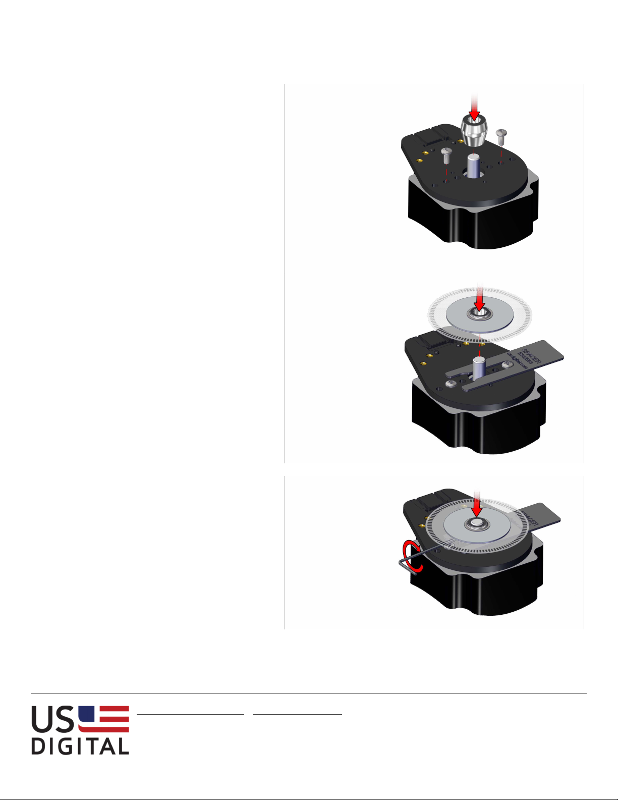
Step 1:
Place encoder base onto mounting surface. Slip
centering tool over the shaft and into the center
hole of base. While holding pressure on the
centering tool, tighten mounting screws. Remove
centering tool.
Step 2:
Place spacer tool around shaft. Slip hubdisk
assembly onto shaft with codewheel disk towards
top until it bottoms out against spacer tool.
Step 3:
Tighten set screw with provided hex wrench while
pressing down on hub. Remove spacer tool.
2 – 3 in-lbs torque
[email protected] ▪ www.usdigital.com
Local: 360.260.2468 ▪ Sales: 800.736.0194
Support: 360.397.9999 ▪ Fax: 360.260.2469
1400 NE 136th Ave. ▪ Vancouver, Washington ▪ 98684 ▪ USA
2.0
Page 1
Page 2
E6 Differential Assembly Instructions
Module Screws
Cover Screws
2 – 4 in-
lbs torque
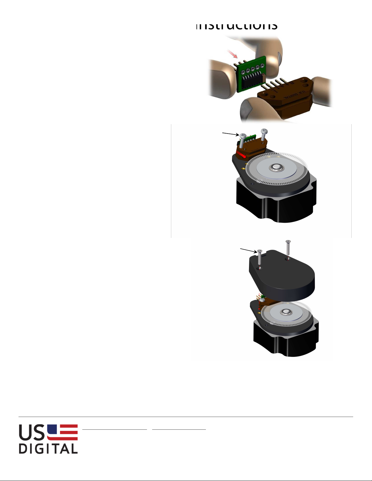
Step 4:
Press line driver onto module pins until it reaches
the end of its motion.
Caution!
To avoid injury make sure that the line driver is
held properly (as shown) during installation,
module pins are sharp!
3.5 – 4 in-lbs torque
Step 5:
Orient module with connector pins toward the top.
Gently slide module onto base. Fit module onto
the two alignment pins on base and secure with
two 4-40 x 1/2” pan head screws (supplied).
Step 6:
Place cover over assembly and secure with two 4-40
x 5/8" flat head screws (supplied).
[email protected] ▪ www.usdigital.com
Local: 360.260.2468 ▪ Sales: 800.736.0194
Support: 360.397.9999 ▪ Fax: 360.260.2469
1400 NE 136th Ave. ▪ Vancouver, Washington ▪ 98684 ▪ USA
2.0
Page 2
 Loading...