

Page 1
E5 Single-Ended Assembly Instructions
Please Note: These instructions apply to the E5 single-ended version only.
for G-Option base
Hub Set Screw:
2 – 3 in-lbs torque
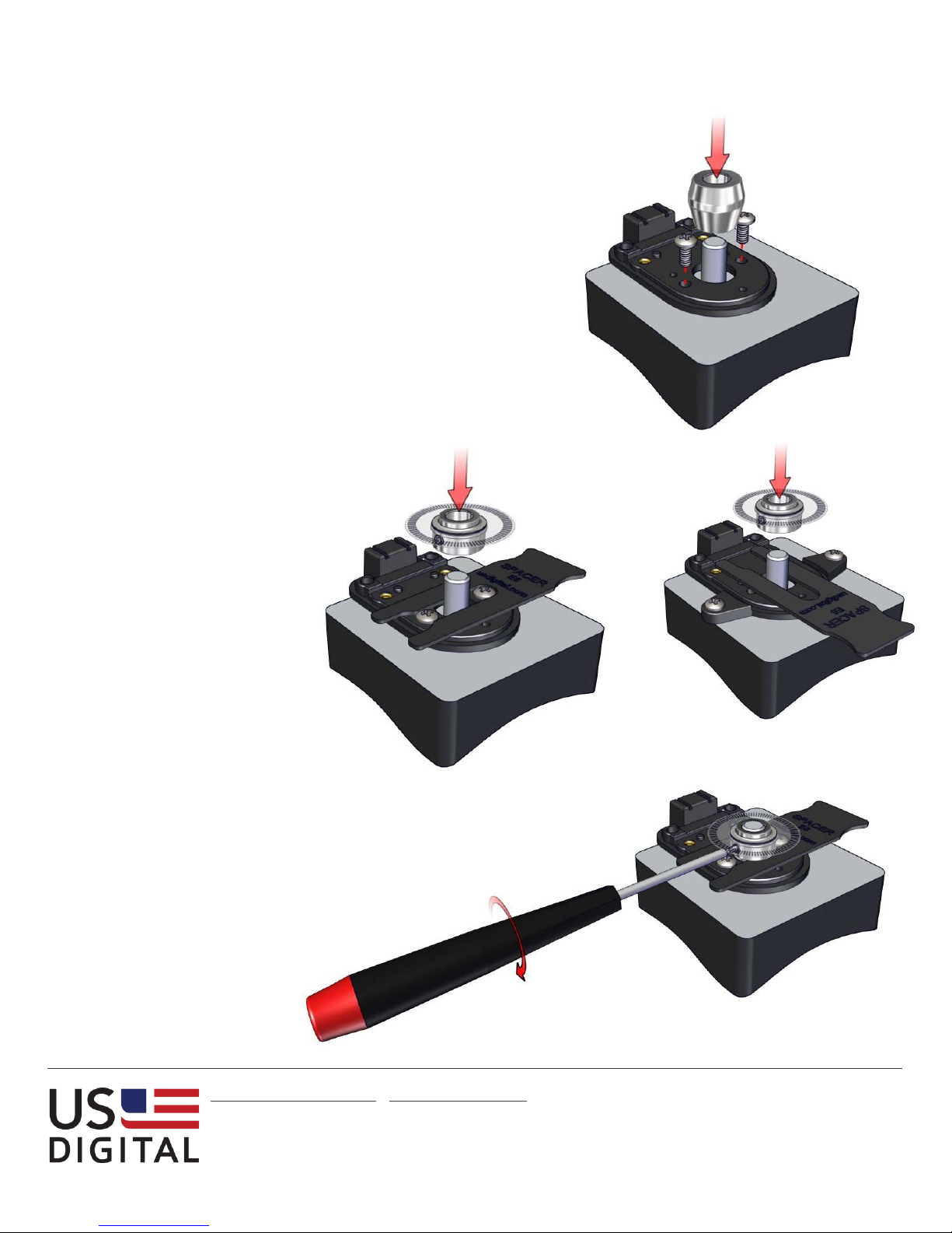
Step 1:
Secure base to mounting surface using two or three
screws. Slip the centering tool over shaft and into
center hole of base. Tighten mounting screws.
Remove centering tool.
Transfer Adhesive: Contact US Digital technical
support for mounting assistance.
Step 2:
Place spacer tool around shaft.
Slip hub disk assembly onto
shaft with codewheel disk
towards top until it bottoms out
against spacer tool.
Note: Alternate spacer
orientations may be required
depending on base/mounting
configuration.
Alternate spacer tool orientation
Step 3:
Tighten set screw with hex
wrench provided while pressing
down on hub.
[email protected] ▪ www.usdigital.com
Local: 360.260.2468 ▪ Sales: 800.736.0194
Support: 360.397.9999 ▪ Fax: 360.260.2469
1400 NE 136
th
Ave. ▪ Vancouver, Washington ▪ 98684 ▪ USA
8.0
Page 1
Page 2
E5 Single-Ended Assembly Instructions
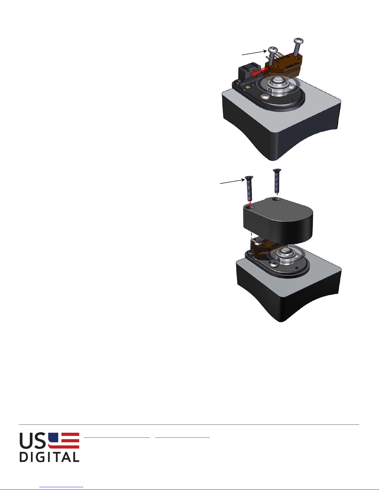
Module Screws
3.5 – 4 in-lbs torque
Cover Screws
2 – 4 in-lbs torque
Step 4:
Slip optical module into
position until the two
alignment pins slip into holes of
module (thick side of module
towards bottom). Secure with 440 x 1/2" screws (supplied).
Step 5:
Place housing (cover) over
assembly and secure with two
4-40 x 5/8" cover screws
(supplied).
[email protected] ▪ www.usdigital.com
Local: 360.260.2468 ▪ Sales: 800.736.0194
Support: 360.397.9999 ▪ Fax: 360.260.2469
1400 NE 136
th
Ave. ▪ Vancouver, Washington ▪ 98684 ▪ USA
8.0
Page 2
 Loading...