

Page 1
Page 2

LPX MANUAL SEED TREATER
Introduction
Introduction
Thank you for choosing USC, LLC for your equipment needs. We appreciate your
business and will work diligently to ensure that you are satisfied with your choice.
OVERVIEW
The purpose of this manual is to provide you with the basic information needed to
operate and maintain the LPX manual seed treater. It does not hold USC, LLC
liable for any accidents or injuries that may occur.
OPERATOR RESPONSIBILITIES
As the purchaser/owner/operator of this equipment and control system, you have an
obligation to install, operate, and maintain the equipment in a manner that minimizes
the exposure of people in your care to any potential hazards inherent in using this
equipment. It is critical that the owner of this equipment:
Has a clear and documented understanding of the process this machine is
being used in and of any resulting hazards or special requirements arising
from this specific application.
Allow only properly trained and instructed personnel to install, operate, or
service this equipment.
Maintain a comprehensive safety program involving all who work with this
machine and other associated process equipment.
Establish clear areas of staff responsibility (e.g. operation, setup,
sanitation, maintenance, and repairs).
Provide all personnel with necessary safety equipment.
Periodically inspect the equipment to insure that the doors, covers,
guards, and safety devices are in place and functioning, that all safety
instructions and warning labels are intact and legible, and that the
equipment is in good working order.
In addition to the operating instructions, observe and enforce the
applicable legal and other binding regulations, national and local codes.
As the person with the most to gain or loose from working safely, it is important that
you work responsibly and stay alert. By following a few simple rules, you can
prevent an accident that could injure or kill you or a co-worker.
USC, LLCPage 2
Page 3
LPX MANUAL SEED TREATER
Do not operate, clean, or service this equipment until you have read and
understood the contents of this manual. If you do not understand the
information in this manual, bring it to the attention of your supervisor, or
call your local USC dealer for assistance.
Any operator who is known or suspected to be under the influence of
alcohol or drugs should not be allowed to operate the equipment.
Understand and follow the safety practices required by your employer and
this manual.
PAY ATTENTION to what you and other personnel are doing and how
these activities may affect your safety.
Failure to follow these instructions may result in serious personal
injury or death.
RECEIVING YOUR EQUIPMENT
As soon as the equipment is received, it should be carefully inspected to make
certain that it has sustained no damage during shipment and that all items listed on
the packing list are accounted for. If there is any damage or shortages, the
purchaser must immediately notify your USC dealer. Ownership passes to
purchaser when the unit leaves the USC, LLC. premises. The purchaser is
responsible for unloading and mounting all components of the equipment.
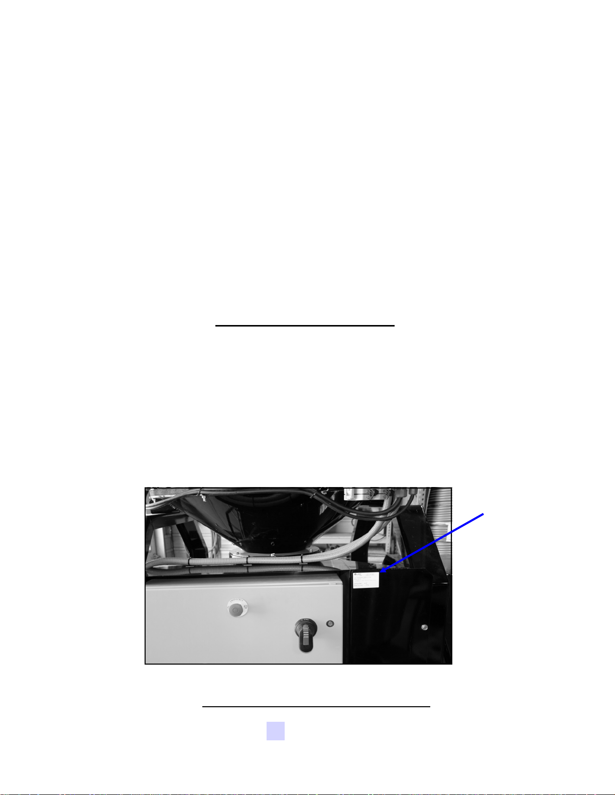
Document the serial number of the machine for future reference. The serial number
is located on the upper right corner of the main panel mounting bracket.
Serial
Number
SERIAL NUMBER:__________________________________
USC, LLC Page 3
Page 4

LPX MANUAL SEED TREATER
Table of Contents
Table of Contents
Section Contents Page #
Legend .................................................................................... 4
Section A Safety Instructions ................................................................. 5
Section B Installation ............................................................................ 12
Section C Mechanical Operation .......................................................... 16
Treater Overview .................................................................... 16
Supply Hopper & Atomizer Chamber ..................................... 17
Rotating Drum ........................................................................ 18
Pump Stand Overview ............................................................ 19
Mix Tank, Calibration Tube & Flow Meter .............................. 20
Pump ...................................................................................... 21
Pump Stand Valves ................................................................ 22
Section D Electrical Operation ............................................................. 24
Main Control Panel ................................................................. 24
Bottom of Main Treater Panel ................................................ 26
Bottom of Main Control Panel ................................................ 27
Pump Stand Control Panel ..................................................... 28
Section E Calibration ............................................................................ 30
Seed Flow Calibration ............................................................ 30
Adjusting the Seed Flow Gate ................................................ 31
Pump Calibration .................................................................... 32
Pump Charts .......................................................................... 34
Treating Seed ......................................................................... 36
Section F Troubleshooting ................................................................... 38
Proximity Switch Adjustment .................................................. 40
Section G Maintenance ......................................................................... 41
Section H Storage .................................................................................. 44
Section I Mechanical Drawings ........................................................... 46
Section J Limited Warranty .................................................................. 89
USC, LLCPage 4
Page 5

LPX MANUAL SEED TREATER
Section
Section
Safety Instructions
AA
Every year accidents in the work place maim, kill, and injure people. Although it
may be impossible to prevent all accidents, with the right combination of training,
operating practices, safety devices, and operator vigilance, the number of accidents
can be significantly reduced. The purpose of this section is to educate equipment
users about hazards, unsafe practices, and recommended hazard avoidance
techniques.
It is very important that operators and maintenance personnel understand the words
and symbols that are used to communicate safety information. Safety words, their
meaning and format, have been standardized for U.S. manufacturers and published
by the American National Standards Institute (ANSI). The European Community
(E.C.) has adopted a different format based on the International Standards
Organization (I.S.O.) and applicable machinery directives. Both formats are
presented below. Graphic symbols are not standardized, but most manufacturers
will use some variation of the ones seen in this manual.
Safety Instructions
SAFETY WORDS AND SYMBOLS
Indicates an imminently hazardous situation which, if not
avoided, will result in death or serious injury.
Indicates a potentially hazardous situation which, if not
avoided, could result in death or serious injury.
Indicates a potentially hazardous situation which, if not
avoided, may result in minor or moderate injury and/or
property damage.
Provides additional information that the operator needs to be
aware of to avoid a potentially hazardous situation.
USC, LLC Page 5
Page 6

LPX MANUAL SEED TREATER
Mandatory Lockout Power Symbol. Disconnect, lockout,
and tagout electrical and other energy sources before
inspecting, cleaning, or performing maintenance on this panel.
International Safety Alert Symbol. The exclamation point (!)
surrounded by a yellow triangle indicates that an injury hazard
exists. However, it does not indicate the seriousness of
potential injury. The exclamation point (!) is also used with the
DANGER, WARNING, and CAUTION symbols so the
potential injury is indicated.
Electrocution Hazard Symbol. This symbol indicates that
an electrocution hazard exists. Serious injury or death could
result from contacting high voltage.
International Electrocution Hazard. This symbol indicates
that an electrocution hazard exists. Serious injury or death
could result from contacting high voltage.
Mandatory Read Manual Action Symbol. (I.S.O. format)
This symbol instructs personnel to read the Operators Manual
before servicing or operating the equipment.
Mandatory Read Manual Action Symbol. This symbol
instructs personnel to read the Operators Manual before
servicing or operating the equipment.
Notice is used to notify people of important installation,
operation, or maintenance information which is not hazard
related.
USC, LLCPage 6
Page 7

LPX MANUAL SEED TREATER
LOCKOUT / TAGOUT PROCEDURES
Lockout/Tagout is the placement of a lock/tag on an energy isolating device in
accordance with an established procedure. When taking equipment out of service
to perform maintenance or repair work, always follow the lockout/tagout procedures
as outlined in ANSI Z344.1 and/or OSHA Standard 1910.147. This standard
“requires employers to establish a program and utilize procedures for affixing
appropriate lockout devices or tagout devices to energy isolating devices and to
otherwise disable machines or equipment to prevent unexpected energizing,
start-up, or release of stored energy in order to prevent injury to employees.”
CONTROLLED STOP
This is the stopping of machine motion by reducing the electrical command signal to
0 (zero) once the stop signal has been recognized.
HAZARD REVIEW
Electrocution Hazard
Electrocution accidents are most likely to occur during maintenance of the
electrical system or when working on or near exposed high voltage wiring.
This hazard does not exist when the electrical power has been disconnected, properly locked, and tagged out.
Automatic Start Hazard
This seed treating system is usually controlled by an automated system
and may start without warning. Failure to properly disconnect, lockout, and
tagout all energy sources of remotely controlled equipment creates a very
hazardous situation and could cause injury or even death. PLEASE STAY
CLEAR AND BE ALERT.
USC, LLC Page 7
Page 8

LPX MANUAL SEED TREATER
YOU are responsible for the SAFE operation and maintenance of your USC, LLC
Seed Treating System. YOU must ensure that you and anyone else who is going to
operate, maintain, or work around the Seed Treating System be familiar with the
operating and maintenance procedures and related SAFETY information contained
in this manual. This manual will take you step-by-step through your working day
and alert you to good safety practices that should be adhered to while operating the
Seed Treating System.
Remember, YOU are the key to safety. Good safety practices not only protect you,
but also the people around you. Make these practices a working part of your safety
program. Be certain that EVERYONE operating this equipment is familiar with the
recommended operating and maintenance procedures and follows all the safety
precautions. Most accidents can be prevented. Do not risk injury or death by
ignoring good safety practices.
LPX Series Seed Treater owners must give operating instructions to operators
or employees before allowing them to operate the machine, and at least annually thereafter per OSHA (Occupational Safety and Health Administration) regulation 1928.57.
The most important safety device on this equipment is a SAFE operator. It is the
operator’s responsibility to read and understand ALL Safety and Operating
instructions in the manual and to follow them. All accidents can be avoided.
A person who has not read and understood all operating and safety instructions
is not qualified to operate the machine. An untrained operator exposes himself
and bystanders to possible serious injury or death.
Do not modify the equipment in any way. Unauthorized modification may impair
the function and/or safety and could affect the life of the equipment.
Think SAFETY! Work SAFELY!
GENERAL SAFETY
1. Read and understand the Operator’s Manual and all safety signs
before operating, maintaining, adjusting or unplugging the LPX
Series Seed Treater.
2. Only trained persons shall operate the seed treater. An untrained
operator is not qualified to operate the machine.
3. Have a first-aid kit available for use should the need arise, and
know how to use it.
USC, LLCPage 8
Page 9

LPX MANUAL SEED TREATER
4. Provide a fire extinguisher for use in case of an accident. Store in a
highly visible place.
5. Do not allow children, spectators or bystanders within hazard area of
machine.
6. Wear appropriate protective gear. This includes but is not limited to:
A hard hat
Protective shoes with slip resistant soles
Protective goggles
Heavy gloves
Hearing protection
Respirator or filter mask
7. Place all controls in neutral or off, stop motor, and wait for all moving
parts to stop. Then disable power source before servicing, adjusting,
repairing, or unplugging.
8. Review safety related items annually with all personnel who will be operating or
maintaining the LPX Series Seed Treater.
OPERATING SAFETY:
1. Read and understand the Operator’s Manual and all safety signs before using.
2. Disconnect and disable electrical supply completely and wait for all moving parts
to stop before servicing, adjusting, repairing or unplugging.
3. Clear the area of bystanders, especially children, before starting.
4. Be familiar with the machine hazard area. If anyone enters hazard area, shut
down machine immediately. Clear the area before restarting.
5. Keep hands, feet, hair and clothing away from all moving and/or rotating parts.
6. Stay away from overhead obstructions and power lines during operation and
transporting. Electrocution can occur without direct contact.
7. Do not operate machine when any guards are removed.
8. Inspect welds and repair if needed.
USC, LLC Page 9
Page 10

LPX MANUAL SEED TREATER
PLACEMENT SAFETY
1. Move only with the appropriate equipment
2. Stay away from overhead power lines when moving Seed Treating System.
Electrocution can occur without direct contact.
3. Be familiar with machine hazard area. If anyone enters hazard areas, shut down
machine immediately. Clear the area before restarting.
4. Operate the Seed Treater on level ground free of debris. Anchor the Seed
Treater to prevent tipping or upending.
Before placement of the Seed Treater, be sure that ground is
reasonably level. The Seed Treater may topple or work
improperly if the ground is too uneven, damaging the
equipment and/or causing personal injury.
MAINTENANCE SAFETY
1. Review the Operator’s Manual and all safety items before
working with, maintaining or operating the Seed Treating
System.
2. Place all controls in neutral or off, stop motors, disable power
source, and wait for all moving parts to stop before servicing,
adjusting, repairing or unplugging.
3. Follow good shop practices:
Keep service area clean and dry.
Be sure electrical outlets and tools are properly grounded.
Use adequate light for the job at hand.
4. Keep hands, feet, hair and clothing away from all moving and/or rotating parts.
5. Clear the area of bystanders, especially children, when carrying out any
maintenance and repairs or making any adjustments.
6. Before resuming work, install and secure all guards when maintenance work is
completed.
7. Keep safety signs clean. Replace any sign that is damaged or not clearly visible.
USC, LLCPage 10
Page 11

LPX MANUAL SEED TREATER
SAFETY SIGNS
1. Keep safety signs clean and legible at all times.
2. Replace safety signs that are missing or have become illegible.
3. Replaced parts that displayed a safety sign should also display the current sign.
4. Safety signs are available from your Authorized Dealer.
How to Install Safety Signs:
Be sure that the installation area is clean and dry.
Be sure temperature is above 50
Decide on the exact position before you remove the backing paper.
Remove the smallest portion of the split backing paper.
Align the sign over the specified area and carefully press the small portion
o
F (10oC).
with the exposed sticky backing in place.
Slowly peel back the remaining paper and carefully smooth the remaining
portion of the sign in place.
Small air pockets can be pierced with a pin and smoothed out using the
piece of sign backing paper.
Located on the USC equipment you will find safety labels.
Always be sure to read and follow all directions on the labels.
Guards provided with USC Seed Treater are to remain in
place during operation.
USC, LLC Page 11
Page 12

LPX MANUAL SEED TREATER
Section
Section
Installation
BB
The following steps outline the initial set-up of your USC Seed Treating system:
Installation
HIGH VOLTAGE ~ Always disconnect the power source
before working on or near the control panel or lead wires.
HIGH VOLTAGE ~ Use insulated tools when making
adjustments while the controls are under power.
Permanent installation may require additional electrical cords,
liquid hose, and air lines, since each installation is unique.
SET-UP
1. Clear the area of bystanders, especially small children, before moving.
2. Be sure there is enough clearance from overhead obstructions and power lines or
other equipment to move the machine into its working position.
3. Using a forklift, place the seed treater in the desired position on a level surface.
USC highly recommends that the seed treater be set up inside a
building or any covered structure to protect the machine from
weathering.
4. Remove any boxes and cords from the drum of the treater.
Inlet
Front
Rear
Discharge
USC, LLCPage 12
Page 13
LPX MANUAL SEED TREATER
5. Install the four provided legs and set up on a level surface, preferably concrete.
When all four legs are mounted in the same pin hole, the seed treater has a slight
slope to allow seed to travel through the machine. The pin holes are approximately
2” apart.
If more slope is desired, the rear legs can be dropped an additional pin
hole.
6. Anchor the seed treater in position to prevent the machine from moving during
operation.
7. Inspect machine thoroughly for screws, bolts, fittings, etc. which may have come
loose during shipping.
8. The pump stand(s) should be placed on level ground close to the seed treater.
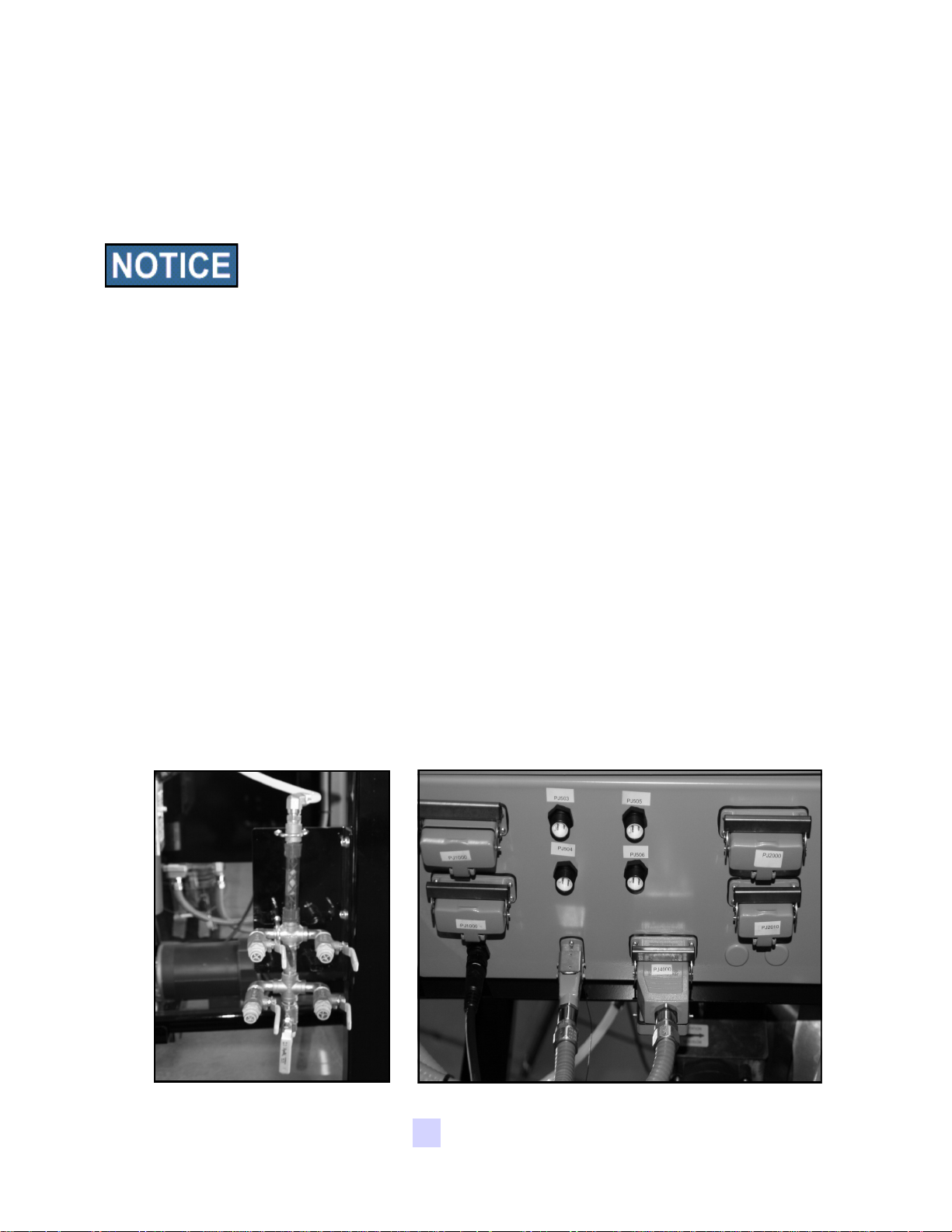
9. Attach the chemical tubing from the pump stands(s) to the atomizer plumbing on the
seed treater (below left). Additional tubing can be added or removed to
accommodate your set-up.
10. Connect the two wire cord from each pump stand to the bottom of the main treater
panel.
11. Setup the main control panel at a place that is convenient to the operator. This
may include attaching the main control panel to the seed treater, to the wall or to the
control panel stand that will require anchoring.
11. Connect the included grey cords from the main control panel to the main treater
panel. The receptacles are found on the bottom of each of the panels (below right).
Plumbing to Atomizer Main Treater Panel Cord Connections
USC, LLC Page 13
Page 14
LPX MANUAL SEED TREATER
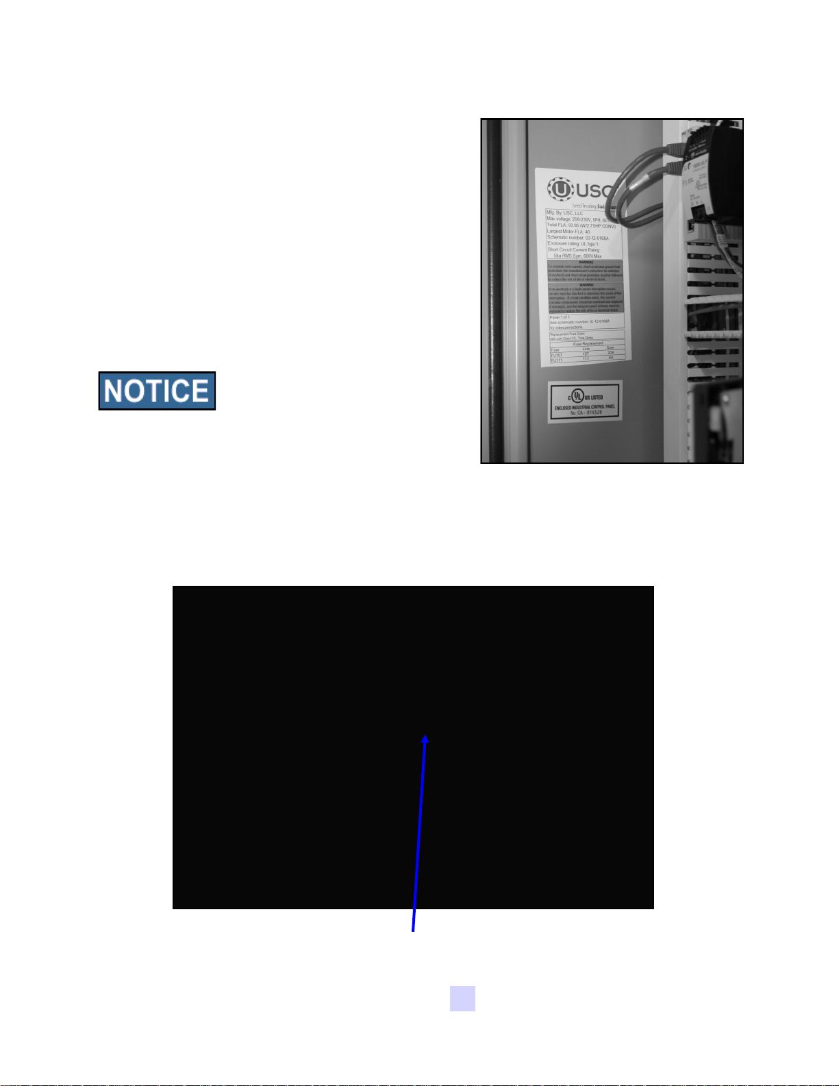
12. Have a certified electrician provide power to
the seed treating system. Provide convenient
shutdown switches, comply with local
electrical codes and ensure that the system is
properly grounded and bonded. The USC
system must be connected to the same
electrical requirements as specified in the
main control panel on the power requirement
tag (right), or the electrical schematic shipped
with the piece of equipment. This will power
the USC LPX seed treater and any attached
conveyors.
Flexible conduit is recommended
for main power supply.
13. Provide 110V single phase power to both the
main control panel and the pump stand
control panel(s).
Power Requirements Tag
14. Reverse the previous steps when removing
the machine from its working position.
Incoming Power Connected To
These Terminals
USC, LLCPage 14
Page 15

LPX MANUAL SEED TREATER
NOTES
USC, LLC Page 15
Page 16

Section
Section
CC
Adjustable
Seed Flow
Gate
Quick
Release
Atomizer
Chamber
Handle
LPX MANUAL SEED TREATER
Mechanical Operation
Mechanical Operation
LPX TREATER OVERVIEW
Supply Hopper
Rotating
Drum
Plumbing
To Atomizer
Conveyor
Receptacles
Main Treater
Panel
Drum Motor
Adjustable
Legs
USC, LLCPage 16
Discharge
Chute
Page 17

LPX MANUAL SEED TREATER
SUPPLY HOPPER
The supply hopper has a capacity of approximately 7 units of seed. The hopper
supplies seed to the atomizing chamber where seed first comes in contact with the
treatment.
The seed flow is controlled by an adjustable seed gate. Refer to “Section E:
Calibration, for instructions on adjusting the seed flow gate. Dry batch calibration
runs will be required in order to determine the seed flow rate . Rates should be
determined in Quantity/Time, this will allow for proper liquid / granular mixtures.
Different seed types may be treated with this equipment. It is
imperative to note that re-calibration of the seed gate setting will be
required with each new seed type.
The hopper is equipped with two proximity switches. The top proximity switch
controls the automatic start and stop of the inlet conveyor, so the supply hopper
does not overflow. This proximity switch is not used on Tower Units. The lower
proximity switch controls the automatic shut-off of the pump(s) when the hopper
runs out of seed. Refer to “Main Control Panel” in Section D, and Section F:
Troubleshooting; “Proximity Switch Adjustment Guide” for more in-depth information
on these proximity switches.
The distribution cone creates a curtain of seed which wraps around the atomizer
head, ensuring that every seed is applied with treatment. (see page 37)
ATOMIZER CHAMBER
The atomizer chamber consists of a
12” hopper extension
Inlet conveyor
Proximity
Switch
patented design which disperses
treatment evenly to each seed. A motor
drives the atomizer head at approximately
1725 RPM’s. As treatment is being
pumped into the atomizer chamber, it
drops into the atomizer head. The
centrifugal force of the spinning head
Pump(s)
Proximity
Switch
forces the treatment to be sprayed out
through a screen covering in all 360
degrees. Meanwhile, seed flows down
out of the supply hopper and down on top
of the distribution cone which disperses
the seed down around the atomizer head.
Adjustable Seed
Gate Lever
The atomizer can be easily accessed by
pulling down on the quick release handle
and sliding the atomizer away from the
Atomizing
Chamber
treater body. (see page 35)
USC, LLC Page 17
Page 18

LPX MANUAL SEED TREATER
ROTATING DRUM
The rotating drum comes in options of 6, 8, and 10 feet and accepts treated seed
through the opening on the hopper end. As seed passes through the length of the
drum it is tumbled, producing accurate and uniform seed coating. The seed then
exits the seed treater out the discharge end of the machine.
Never allow exposure of persons or clothing to the drive shaft,
idler wheels, or the drum during operation. Always have the
safety shields in place during operation.
The time it takes for seed to move through the drum both during and at the end of
the run can be changed by lowering or raising the pins on the legs of the discharge
end of the treater. When the pins are in the same hole on all of the treater legs, the
treater has a natural downward tilt towards the discharge end of the treater.
Lowering the pins on the discharge end’s legs will give the treater more tilt during
operation which will allow seed to travel through the drum at a faster rate. Vice
verse, raising those pins will cause seed to stay in the drum longer.
It is not recommended to lower the discharge end’s pins more
than one hole setting different from the inlet end’s pins. If this is
done, a loss in seed coverage and chemical coating may occur.
On the 6 and 8 foot drum options the LPX manual treater will also come standard
with telescoping fork lift pockets. These pockets can be slid out from underneath
USC, LLCPage 18
Page 19

LPX MANUAL SEED TREATER
PUMP STAND OVERVIEW
Mix Tank
Mix Tank
Motor
Seed Treatment
Return Valve
Seed Treatment
Valve
Flow Meter
Drain
Valve
Scale Shipping
Bracket
Calibration
Tube
Pump
Filter
Seed Treatment
Source Valve
Mix Tank Scale
(optional)
USC, LLC Page 19
Page 20

LPX MANUAL SEED TREATER
MIX TANK
The USC LPX manual seed treater is equipped with a fully modular, manually
controlled pump stand. This pump stand will include a 30 or 60 gallon chemical mix
tank that is of either stainless steel or poly construction. This chemical mix tank will
have electric drive agitation that is turned on or off at the pump stand control panel.
The agitator should be running at all times when treatment is present in the mix
tank to keep the chemical mixed and in a suspended state. The tank is equipped
with a shut-off, drain plug, and drain valve located on the bottom. The top of the
tank also includes 3 extra ports which the operator can use to direct fill into the tank
(see below).
CALIBRATION TUBE
The LPX manual pump stand may also be equipped with a calibration tube which is
used to determine the liquid flow rate. The calibration tube measures in ounces on
a 0-340 scale. Three-way valves direct liquid from different areas to keep all liquid
contained. This creates a closed chemical system so that the operator can
manually calibrate the chemical flow rate without handling any of the chemical.
FLOW METER
A in-line chemical flow meter is another option for the LPX manual pump stand. A
flow meter is used to perform real-time chemical flow adjustments and monitoring
without the operator having to handle the chemical. The flow meter reading will be
displayed on the pump stand control panel.
USC, LLCPage 20
Page 21
LPX MANUAL SEED TREATER
PUMP
The LPX manual pump stand utilizes a variable speed peristaltic pump and special
norprene pump tubing for liquid metering. The pump comes equipped with either 1,
2 or 3 heads. Liquid will only come into contact with the inside diameter of the
pump tubing and not the pump. This allows for easy cleanup and less maintenance
of the pump.
To open the pump head, lift the lever upward. Place the pump tubing inside the
pump head so it fits inside the notches and above the rollers. Lower the lever back
down to close the pump head, clamping the hose inside the head. Wear or
fatiguing of the tubing within the pump head due to compression is normal. When
tubing becomes worn or chemical rates begin to slow down, open the pump head
and move the tubing to a different position. If the entire piece of tubing becomes
worn, simply replace with a new section. When not using the seed treater for
several days or when storing, open the pump head and remove the tubing to
prevent any extra compression. Worn tubing should be moved to a different
position every week to prevent additional wear.
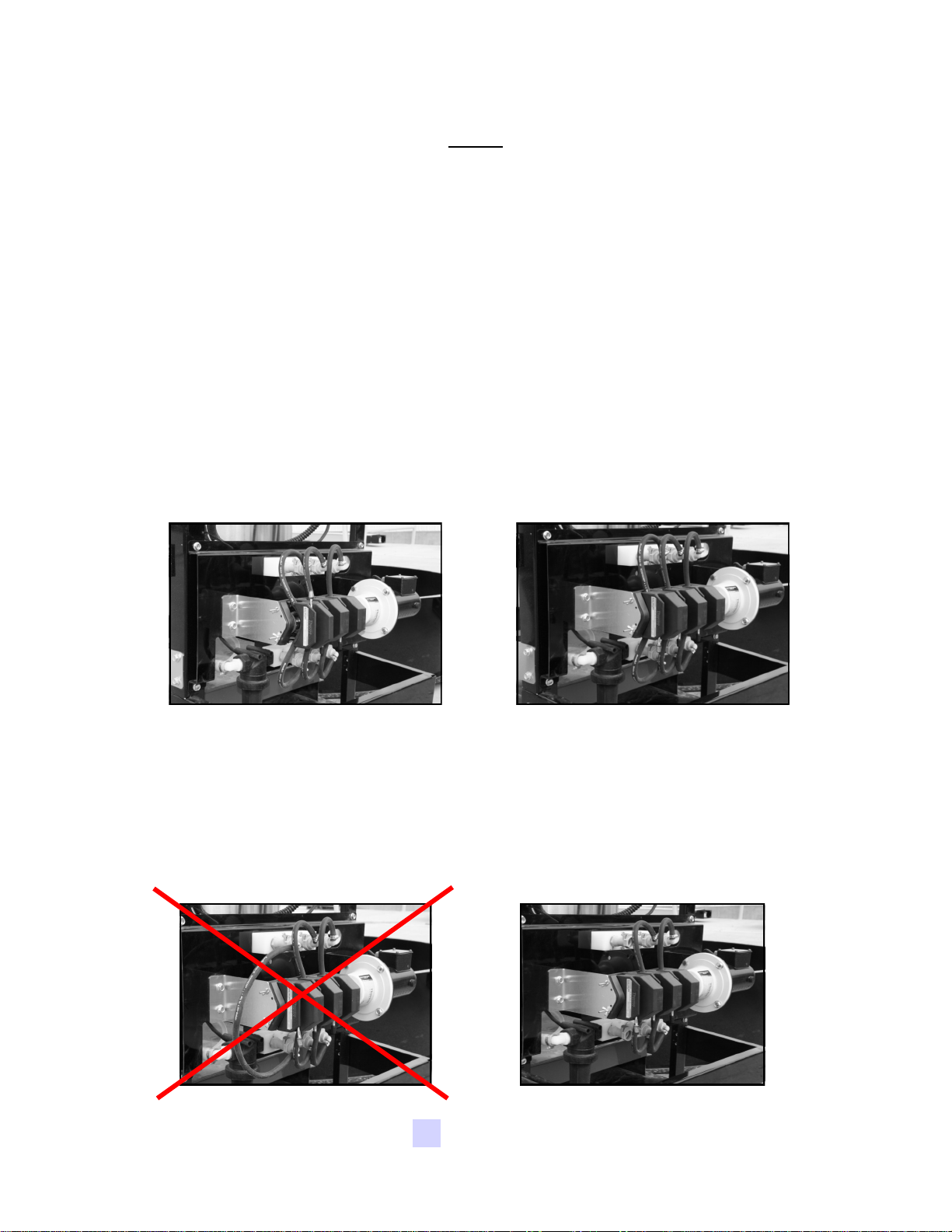
Pump Head Open Pump Head Closed
If a very low rate is needed, a section of tubing can be removed to force the pump
motor to run at a higher speed. This allows for a more consistent flow rate. When
removing the tubing, uncouple it from the manifold (below, right). If the tubing is
unclamped from the pump head but left coupled in the manifold (below, left), the
pump will suck air and cause flow rates to be very inconsistent.
USC, LLC Page 21
Page 22
LPX MANUAL SEED TREATER
PUMP STAND VALVES
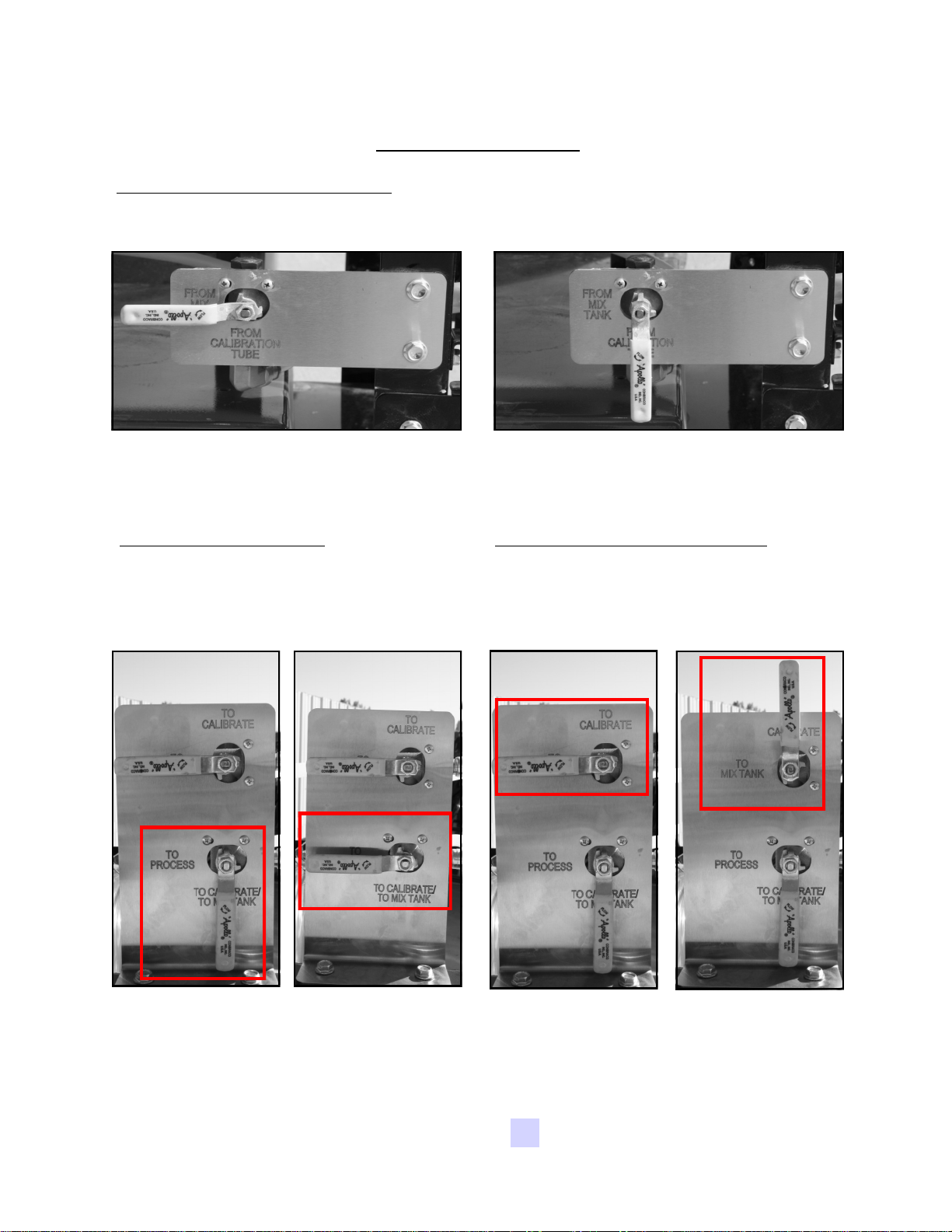
Seed Treatment Source Valve:
This valve controls where the pump is drawing liquid
from. It allows liquid to be pulled from either the bottom of the mix tank or the
calibration tube.
Drawing chemical from the bottom of
the Mix Tank
Seed Treatment Valve:
This valve
controls the direction of the liquid
coming from the pump. It will either
direct liquid to the Atomizer or to the
Seed Treatment Return Valve.
Drawing chemical from the bottom of
the Calibration Tube
Seed Treatment Return Valve:
This
valve directs the liquid coming from the
To Calibrate / To Mix Tank side of the
Seed Treatment Valve to either fill the
Calibration Tube or return to the Mix Tank.
Pumping liquid to
the Seed Treatment
Return valve.
Pumping liquid to
atomizer. Used
when treating
seed.
USC, LLCPage 22
Pumping liquid into
the top of the mix
tank for
recirculation
purposes.
Pumping liquid into
the top of the
calibration tube for
calibration
purposes.
Page 23

LPX MANUAL SEED TREATER
Proper calibration of the liquid system is critical to achieve a proper granular/
chemical mixture. Use the calibration procedure on page 32 to determine liquid
flow rate.
Emptying the remaining liquid can be done by using the reverse function on the
control panel. This will pump liquid back into the mix tank. Then drain the
remaining liquid into a suitable container. Clean water should be pumped through
the calibration tube and mix tank when finished.
Always dispose of chemical or diluted chemical according to your
local, state, and federal regulations.
Only you, the operator, can determine the length of time required
to completely rinse all chemical residue from the tank and
plumbing system.
USC, LLC Page 23
Page 24

LPX MANUAL SEED TREATER
Section
Section
Electrical Operation
DD
Refer to the control panel and the electrical schematic for proper voltage and
amperage of the machine. All green switches will illuminate when activated. The
control panel is run from 110V power and controls the following functions:
Electrical Operation
HIGH VOLTAGE ~ Always disconnect the power source
before working on or near the control panel or lead wires.
HIGH VOLTAGE ~ Use insulated tools when making
adjustments while the controls are under power.
AUTHORIZED PERSONNEL only shall work on the control
panel. Never allow anyone who has not read and familiarized
themselves with the owner’s manual to open or work on the
control panel.
MAIN CONTROL PANEL
2
5
1
3 4
6
USC, LLCPage 24
7
Page 25
LPX MANUAL SEED TREATER
Main Controls Explained
1. Hand/Off/Auto Switch for Pumps:
This switch controls all the connected pump
stands and any device connected to the auxiliary port. This switch must be
activated before either pump will operate in forward or reverse.
Hand Position:
When the switch is placed in “Hand”, the pump(s) will run only
when you have turned the pump(s) switches are placed in auto and forward or
reverse and the speed has been adjusted.
Auto Position:
When the switch is placed in
“AUTO”, the pump(s) will only run when the lower
proximity switch located in the supply hopper is
covered and the atomizer is running. The proximity
switch determines when seed is present in the
hopper. When the proximity switch does not detect
seed, a timer relay located inside the control panel
will automatically shut off the pump(s) a predetermined amount of time after the hopper has
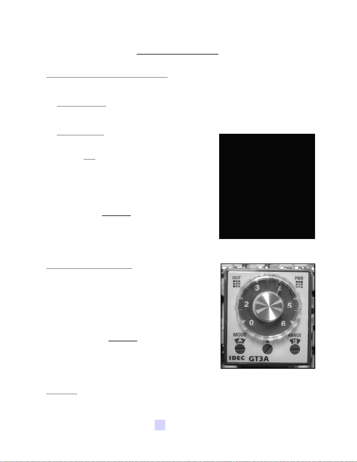
emptied. The timer relay (right) located in the main
panel is set to Mode “D” and has an adjustable
knob with settings from 0-6. Each number
represents the number of seconds from the time the
hopper empties until the pumps will shut off. The
time delay allows all seed in the hopper to have an
equal coverage.
2. Inlet Conveyor Switch:
This switch controls the
inlet conveyor in conjunction with a timer relay. When
the switch is turned on, the conveyor will run until seed
covers the proximity switch mounted near the top of the
supply hopper, at which time the conveyor will turn off
automatically. The inlet conveyor will remain off until
seed has dropped below the proximity switch. A timer
relay (right) will turn the conveyor back on after a
pre-determined time. The timer relay located inside the
main panel is set to Mode “A” and has an adjustable
knob with settings from 0-6. Each number represents
the number of seconds from the time the proximity
switch is uncovered to when the conveyor will turn back
on. The time delay prevents the conveyor from turning
on and off too quickly.
3. Drum:
This switch allows the operator to turn the drum on or off. The drum
controls automatically have a soft-start feature incorporated into them.
USC, LLC Page 25
Page 26
LPX MANUAL SEED TREATER
4. Drum Speed Adj.:
This dial allows the operator to adjust the speed at which the
drum is rotating.
5. Outlet Conveyor Switch:
This switch allows the operator to turn the outlet
conveyor on or off.
6. Atomizer:
This switch allows the operator to turn the rotary driven atomizer on
or off for primary distribution of product on the seed. This switch must be turned on
before the seed treating process begins and before the pump(s) will operate in
“Auto”.
7. Atomizer Speed Adj.:
This dial allows the operator to adjust the speed at which
the atomizer is spinning.
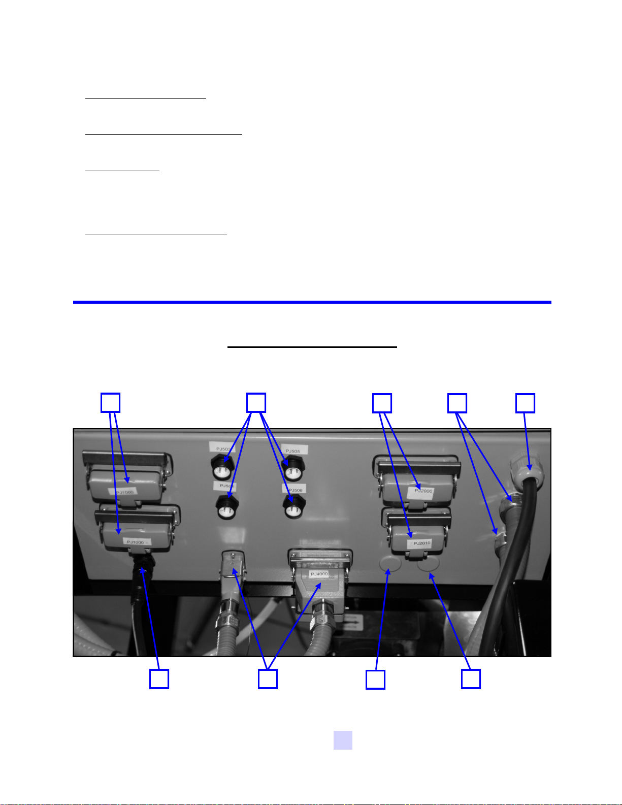
Bottom of Main Treater Panel
1 2
6
3 4
8
5
9 7
USC, LLCPage 26
Page 27
LPX MANUAL SEED TREATER
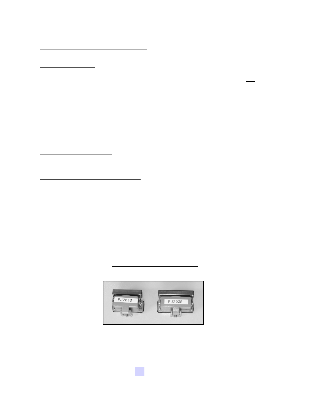
1. Automated Controls Receptacles:
automated controls to the main treater panel.
2. Auxilliary Ports:
liquid systems or a dry additive feeder to tie in with the automatic shut-off function.
The Hand/Off/Auto switch will control the secondary system. This port does not
supply power to a secondary unit.
These ports will allow a LPX manual pumps stand, additional
3. Manual Controls Receptacles:
manual control panel to the main treater panel.
4. Conveyor Controls Panel Wiring:
panel to the main treater panel.
5. Drum Motor Wiring:
panel.
6. Atomizer Receptacle:
treater panel. The atomizer can be unplugged so it can be removed from the
machine for maintenance.
This wire connects the drum motor to the main treater
This receptacle connects the atomizer motor to the main
7. Seed Wheel Panel Receptacles:
the seed wheel panel to the main treater panel. They will also replace the inlet and
pump proximity switch wiring.
These receptacles are used for connecting
These receptacles are used to connect the
These wires connect the conveyor controls
These receptacles are used for connecting
8. Inlet Proximity Switch Wiring:
that is used to control the inlet conveyor to the main treater panel. This wiring will
be removed if a seed wheel is being used with the treater.
9. Pump(s) Proximity Switch Wiring:
switch to the main treater panel. This wiring will be removed if a seed wheel is being used in with the treater
Bottom of Main Control Panel
Both of these ports will use the included grey cords to connect the main control panel
to the bottom of the main treater panel. This will allow the two panels to communicate
with each other.
This wiring connects the inlet proximity switch
This wiring connects the pump(s) proximity
USC, LLC Page 27
Page 28
LPX MANUAL SEED TREATER
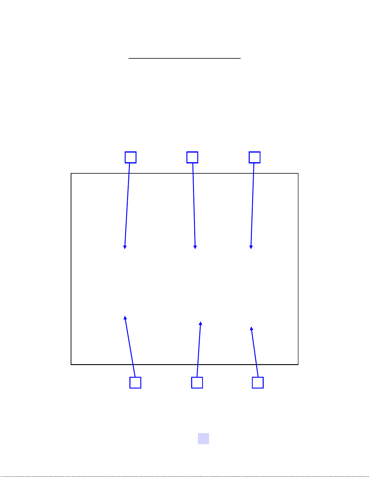
PUMP STAND CONTROL PANEL
Refer to the control panel power requirement tag and the electrical schematic for
proper voltage and amperage of the machine. The control panel is run from 110V
power and controls the following functions:
1 2 3
4 5 6
USC, LLCPage 28
Page 29

LPX MANUAL SEED TREATER
Pump Controls Explained
1. Chemical Pump Switch:
When this switch is turned to “HAND”, the chemical pump will run.
When the switch is turned to “AUTO”, the chemical pump will only run when
the main control panel H-O-A switch is turned to “HAND” or “AUTO”. The
2-wire cord must be connected to the seed treater before this feature will work.
When the main control panel H-O-A switch is turned to “HAND”, the chemical
pump will run at any time. When turned to “AUTO”, it will only run when the
proximity switch located in the bottom of the seed treater supply hopper is
covered and the atomizer is running. The proximity
switch determines when seed is present in the
hopper. When the proximity switch does not detect
seed, a timer relay located inside the control panel
will automatically shut off the chemical pump a
pre-determined amount of time after the hopper
has emptied. The timer relay (right) located in the
seed treater main panel is set to Mode “D” and has
an adjustable knob with settings from 0-6. Each
number represents the number of seconds from the
time the hopper empties until the pump shuts off.
The time delay allows all seed in the hopper to
have an equal coverage.
2. Agitation:
This switch allows the operator to turn the chemical mixer/agitator
on or off to allow for a perfectly mixed application of the seed treatment.
3. High Speed Mixer:
This dial allows the operator to change the speed at
which the agitator is mixing the chemical.
4. Pump Voltmeter/Flow Meter Display:
Displays either the DC voltage for the
pump or if pump stand is equipped with a flow meter, then the current flow rate
going through the flow meter will be displayed. As the pump’s speed is increased
or decreased, this number will also increase or decrease.
5. Chemical Pump Direction:
This switch allows the operator to change the
pump direction between forward and reverse. It has a safety feature that will not
allow the operator to switch from forward to reverse or vice-versa without
momentarily stopping and releasing the switch in the center position.
6. Liquid Adj. Dial:
This dial allows the operator to adjust the speed of pump.
The setting should be chosen in relation to the application rate for the treatment
being applied to the seed.
USC, LLC Page 29
Page 30
LPX MANUAL SEED TREATER
Section
Section
Calibration
EE
Calibration of both the seed flow and liquid portions of the equipment is necessary
for accurate treatment of seed.
The following steps illustrate how to calibrate the seed flow for a LPX manual series
seed treater. A stop watch, ladder, and a known weight of seed will be needed
during the calibration process.
1. Position all equipment so that you are able to run a dry batch of seed through
the seed treater and catch it back into a container. This will allow you to easily
run the seed through again to recalibrate or begin treating.
Calibration
If you prefer metric measurements, please refer to the conversion
chart on page 37.
SEED FLOW CALIBRATION
If the seed treater is equipped with a Seed Wheel, refer to the Seed
Wheel operator’s manual for seed flow calibration instructions.
2. Set the adjustable seed gate lever at a position that you and your equipment
can handle. (all the way open – approximately 1900 lbs/min. or 860 kg/min for
the LPX 2000 and approximately 950 bushels/hr. or 430 kg/min) Refer to page
31 for adjusting the seed gate. Calibrations should be done with at least 40
units or 2000 lbs.
3. Place the drum and any conveyors to the “ON” position.
4. When equipment is in position, begin running seed through the seed treater.
Using the stop watch, begin timing as soon as the seed lands in the bottom of
the supply hopper.
Be sure the supply hopper stays full at all times. If seed does not
pile-up in the hopper, the seed calibration will not be accurate.
5. Stop timing after all seed has left the supply hopper.
6. Calculate the seed flow rate: Total Pounds per Minute.
EXAMPLE: 2000 pounds takes 1 minutes and 38 seconds, or 98 seconds
2000 pounds / 98 seconds = 20.4 pounds/seconds
20.4 x 60 seconds = 1224 lbs/minute
1224 / 100 = 12.24 cwt/min (hundred weight per minute)
Different seed sizes and different seed types will tend to flow at
different rates. Be sure to check calibration when changing to a
different seed size or seed type.
USC, LLCPage 30
Page 31
LPX MANUAL SEED TREATER
ADJUSTING THE SEED FLOW GATE
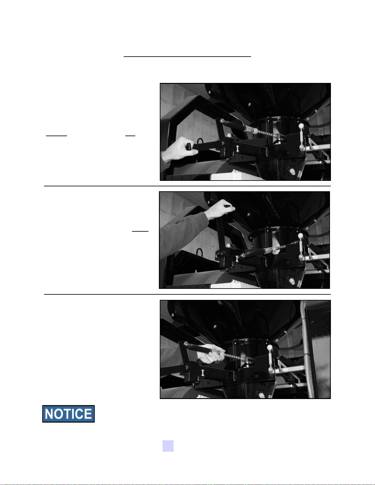
14. Below are pictures that illustrate how to open, close, and adjust the opening of
the seed flow gate.
When the black lever is pulled
down, the seed gate is in the
closed position, and will not
allow seed to flow through
When the black lever is pushed
up, the seed gate is in the open
position, and seed will flow
through
Regulate the amount of seed
flowing through the seed treater
by using the spring-loaded
coupler and moving it to a
different notch. The more
notches exposed, the higher the
seed flow.
If the seed treater is equipped with a seed wheel, the adjustable seed
flow gate should always be left in the most wide open position. If the
seed gate is not open fully, seed flow will be diminished and may
even cause seed to back up into the seed wheel.
USC, LLC Page 31
Page 32
LPX MANUAL SEED TREATER
PUMP CALIBRATION
The following steps illustrate how to calibrate the pump on an LPX manual series
seed treater. A stop watch will be needed during the calibration process.
If the seed treater is equipped with a flow meter, refer to the Flow
Meter operator’s manual for pump calibration instructions.
1. Lock down the pump tubing in the pump head(s) (page 21).
2. Premix enough liquid for the amount of seed you will be treating and pour into
the mix tank. It’s always a good practice to mix up 20% extra slurry to help fill all
the lines. Turn on the mix tank and allow liquid to mix.
3. Turn the “SEED TREATMENT SOURCE” valve to the “MIX TANK” position, the
“SEED TREATMENT” valve to the “CALIBRATE” position, and the “SEED
TREATMENT RETURN” valve to “MIX TANK”.
4. Turn the chemical pump direction switch to “FORWARD”.
5. Turn the “Hand/Off/Auto” switch on the main control panel to the
“Hand” position and the “Hand/Off/Auto” switch on the pump
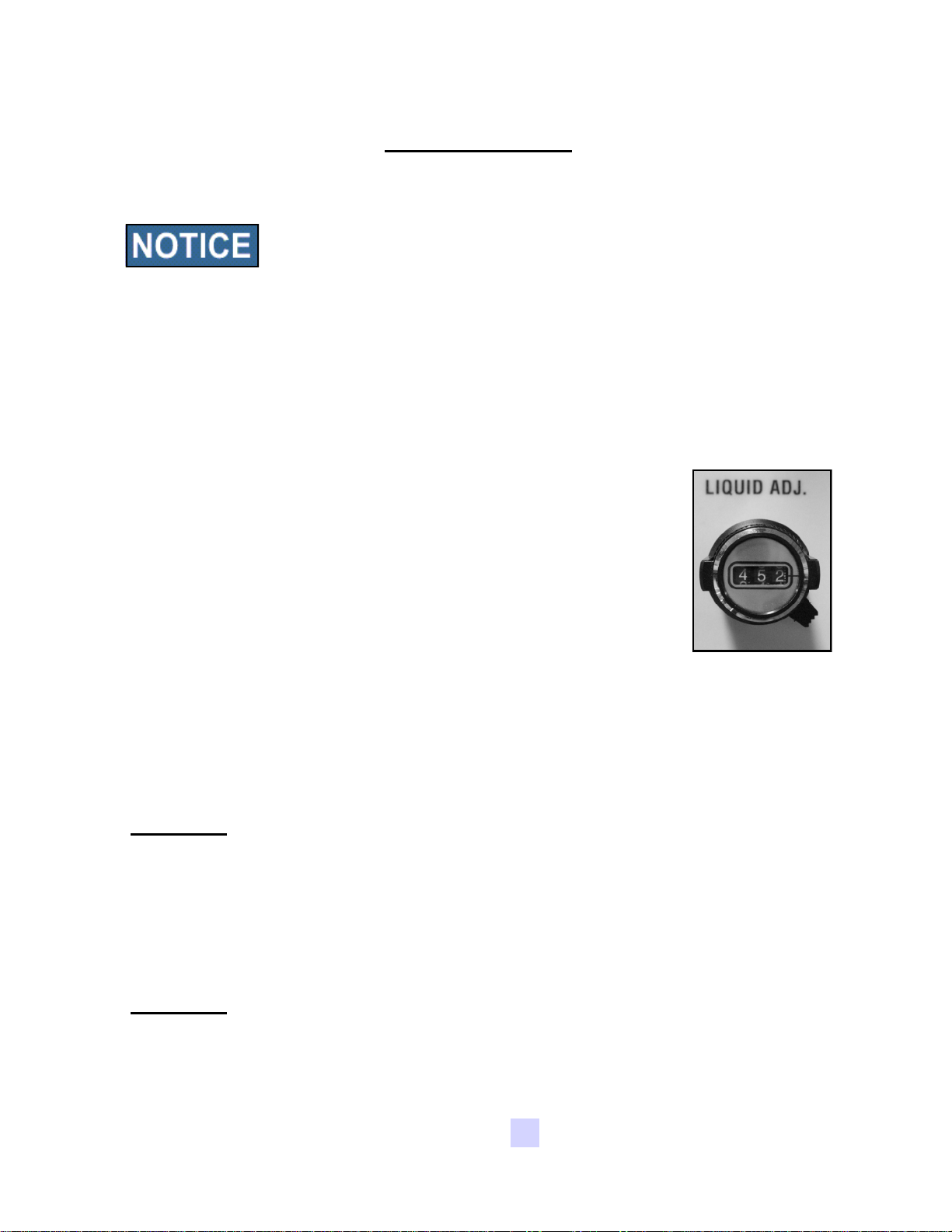
stand control panel to the “Auto” position. Then set the Liquid
Adjust dial on the pump stand control panel (right) to about
“500” or half speed. The liquid should begin re-circulating from
the bottom of the mix tank, through the pump, and back into the
top of the mix tank.
6. Allow the pump to re-circulate liquid for approximately 15 minutes to ensure all
air has been removed from the liquid lines. This will also help “break-in” the
pump tubing, which is critical before checking pump calibration.
7. After you have allowed the liquid to re-circulate you are ready to calibrate the
pump. Determine the number of ounces needed in one minute.
EXAMPLE: The seed treatment slurry rate is 4 ounces per cwt.
Seed Flow Rate = 12.24 cwt/min. x 4 oz./cwt. = 49 oz./min.
49 oz. is the rate the pump should be pumping in one minute.
8. Set the Liquid Adjustment dial. You can use the chart on page 34 to find a
starting point.
EXAMPLE: The ounces needed in one minute = 49 oz/min. Assume we are
using a 6-600 Masterflex pump with one P/S pump head. An
approximate starting point is 58.9 volts.
USC, LLCPage 32
Page 33

LPX MANUAL SEED TREATER
9. Using the stop watch, determine the pump flow rate. Keeping the pump running,
position a container under the “SEED TREATMENT RETURN” valve to catch the
chemical. If the pump stand has a calibration tube then no container will be
needed since the chemical will fill the calibration tube instead. Then, place the
“SEED TREATMENT RETURN” valve to the “CALIBRATION TUBE” position. At
this time, liquid will begin to fill the calibration tube. When liquid reaches 0 (zero)
or an even number, begin timing for one minute. (see Figure 1, below)
10. As soon as one minute is up, position the “SEED TREATMENT RETURN” valve
to “MIX TANK”. Read the level on the side of the calibration tube (see Figure 2,
below) or the container that was used to catch the chemical. This number
should equal the number of ounces needed to flow through the pump in one
minute. If the ounces needed per minute have not been met, re-adjust the pump
speed up or down accordingly and repeat steps 9 & 10 until the liquid flow rate
has been matched.
Figure 1
Liquid at 0 oz.
Figure 2
Liquid at 35 oz.
after 1 minute
USC, LLC Page 33
Page 34
LPX MANUAL SEED TREATER
Standard Data
Below are two charts that show the potential volts and oz./min of three different pump
configurations at different dial settings.
All calibrations were done using water. Numbers are not exact;
only use these numbers as a starting point or for troubleshooting.
6-600 RPM Motor
& P/S Pump Head,
with Masterflex L/S 35
Pump Tubing
Volts OZ./Min.
10.5 7.4
14.6 10.5
18.8 14.1
22.9 17.7
27.0 21.3
31.2 24.9
35.3 28.5
39.4 32.1
43.6 35.7
47.7 39.3
51.8 42.9
55.9 46.5
6-600 RPM Motor
& 2 P/S Pump Heads,
with Masterflex L/S 35
Pump Tubing
Volts OZ./Min.
10.5 14.8
14.6 21
18.8 28.2
22.9 35.4
27.0 42.6
31.2 49.8
35.3 57.0
39.4 64.2
43.6 71.4
47.7 78.6
51.8 85.8
55.9 93.0
1/4 HP 2500 RPM Motor
& 3 P/S Pump Heads,
with Masterflex L/S 35
Pump Tubing
Volts OZ./Min.
10.5 25.0
14.6 35.5
18.8 47.6
22.9 59.8
27.0 72.0
31.2 84.1
35.3 96.3
39.4 108.4
43.6 120.6
47.7 132.8
51.8 144.9
55.9 157.1
60.1 50.1
64.2 53.7
68.3 57.3
72.5 60.9
76.6 64.5
80.7 68.1
84.9 71.7
89.0 75.3
60.1 100.2
64.2 107.4
68.3 114.6
72.5 121.8
76.6 129.0
80.7 136.2
84.9 143.4
89.0 150.6
USC, LLCPage 34
60.1 169.2
64.2 181.4
68.3 193.6
72.5 205.7
76.6 217.9
80.7 230.0
84.9 242.2
89.0 254.4
Page 35
LPX MANUAL SEED TREATER
Metric Data
Below are two charts that show the potential volts and ml./min of three different pump
configurations at different dial settings.
All calibrations were done using water. Numbers are not exact;
only use these numbers as a starting point or for troubleshooting.
6-600 RPM Motor
& P/S Pump Head,
with Masterflex L/S 35
Pump Tubing
Volts Ml./Min.
10.5 219
14.6 302
18.8 417
22.9 524
27.0 630
31.2 737
35.3 843
39.4 950
43.6 1,056
47.7 1,162
51.8 1,268
55.9 1,375
60.1 1,482
6-600 RPM Motor
& 2 P/S Pump Heads,
with Masterflex L/S 35
Pump Tubing
Volts ml./Min.
10.5 438
14.6 604
18.8 834
22.9 1048
27.0 1260
31.2 1474
35.3 1686
39.4 1900
43.6 2,112
47.7 2,324
51.8 2,536
55.9 2,750
60.1 2,964
1/4 HP 2500 RPM Motor
& 3 P/S Pump Heads,
with Masterflex L/S 35
Pump Tubing
Volts ml./Min.
10.5 740
14.6 1,020
18.8 1,409
22.9 1,770
27.0 2,128
31.2 2,490
35.3 2,848
39.4 3,209
43.6 3,567
47.7 3,925
51.8 4,283
55.9 4,645
60.1 5,006
64.2 1,588
68.3 1,695
72.5 1,800
76.6 1,908
80.7 2,014
84.9 2,121
89.0 2,227
64.2 3,176
68.3 3,390
72.5 3,600
76.6 3,816
80.7 4,028
84.9 4,242
89.0 4,454
USC, LLC Page 35
64.2 5,364
68.3 5,726
72.5 6,080
76.6 6,445
80.7 6,803
84.9 7,165
89.0 7,523
Page 36

LPX MANUAL SEED TREATER
TREATING SEED
1. Prime the line going to the atomizer by turning the Atomizer switch to “ON” and
turn the “SEED TREATMENT” valve to “PROCESS”. Next turn the pump
direction switch to “FORWARD” and the “Hand/Off/Auto” switch on the main
control panel to “Hand”. Liquid should begin pumping up to the atomizer. After
the line has been primed, turn the “Hand/Off/Auto” switch to “Auto”. Additional
liquid can be pumped up into the atomizer and into the drum to guarantee
coverage of the first seed that passes through the machine.
Do NOT pump liquid into the atomizing chamber when the atomizer
is “OFF”.
2. Position the “SEED TREATMENT SOURCE” valve to “MIX TANK”.
If you desire to check the total ounces used per batch of seed. Fill
the calibration tube with the amount needed for the batch of seed
(approximately 20% extra to be safe). Then position the “SEED
TREATMENT SOURCE” valve to “CALIBRATION TUBE”.
3. Position conveyors, overhead hopper, or seed box so the first seed coming into
the seed treater lands on the lower proximity switch which automatically turns on
the pump(s).
4. Turn the switches to “ON” for the Drum, Atomizer, and any Conveyors being
used. With all motors turned to the “ON” position, you are ready for seed.
5. Begin sending seed into the seed treater. As soon as seed lands on the
proximity switch, the pump will turn on and the seed treating process will begin.
If the first seed is not well coated, the “Hand/Off/Auto” switch can
initially be turned to “Hand” before the seed comes into the treater.
Once the supply hopper is full, the switch can be turned to “Auto”.
6. When all seed has passed through the atomizer, the pump will automatically
shut off.
USC, LLCPage 36
Page 37

LPX MANUAL SEED TREATER
The Illustration below shows how seed passes through the atomizing chamber.
The red represents treatment being dispensed to the seed as it passes through the
chamber. After the seed passes through the atomizer, it goes into the drum where
the coating process is completed.
Seed Gate
Distribution
Cone
Seed Treatment
Line
Atomizer Head
Inoculant Port
Bearing
Conversion Chart
1 ounce = 29.58 milliliters
1 gallon = 3.79 liters
1 kilogram = 2.2 pounds
1 unit = 50 lbs or 22.73 kg
1 bushel = approx. 60 lbs or 27.27 kg
1 cwt = 100 lbs or 45.45 kg
USC, LLC Page 37
Page 38

LPX MANUAL SEED TREATER
Section
Section
Troubleshooting
FF
Troubleshooting
Below is a table describing the most frequent problems and solutions with the USC LPX
Manual Seed Treater. For further assistance, contact your local USC dealer.
Problem Possible Cause Solution
Inlet Conveyor will not turn on. 1. Inlet conveyor proximity
switch is activated.
2. Inlet conveyor proximity
switch is too sensitive.
3. Overload is tripped.
4. Conveyor is plugged into
wrong outlet on seed treater
panel.
Pump will not turn off in “AUTO”
when seed runs out.
Pump will not turn on in “AUTO” 1. Proximity switch is not
1. Proximity switch is dirty.
2. Proximity switch is set too
sensitive.
staying covered.
2. Atomizer is not on.
3. Proximity switch is not
sensitive enough.
4. Pump stand two-wire cord is
not plugged into to treater
main panel.
1. Clean proximity switch
2. Adjust the inlet conveyor
proximity switch sensitivity by
turning the adjustment screw
counter-clockwise (page 40).
3. Reset inlet conveyor
overload.
4. Check to make sure the inlet
conveyor is plugged into the
inlet conveyor receptacle.
1. Clean proximity switch.
2. Adjust the pump proximity
switch sensitivity by turning
adjustment screw counterclockwise (page 40).
1. Make sure proximity switch is
staying covered with seed
2. Turn on atomizer. Atomizer
must be on to run the pump in
Auto.
3. Adjust pump proximity switch
sensitivity by turning the
adjustment screw clockwise
(page 40).
4. Plug the pump stand two-wire
cord into the main treater
panel.
Inlet conveyor won’t shut off
when hopper is full.
1. Seed is not hitting proximity
switch.
2. Proximity switch is not set
sensitive enough.
3. Inlet conveyor is plugged into
wrong receptacle.
USC, LLCPage 38
1. Make sure seed is hitting
proximity switch.
2. Adjust the inlet conveyor
proximity switch by turning the
adjustment screw clockwise
(page 40).
3. Make sure inlet conveyor is
plugged inlet conveyor
receptacle.
Page 39

LPX MANUAL SEED TREATER
Problem Possible Cause Solution
Pump is fluctuating 1. Restriction in tubing.
2. Tubing was not broken-in
properly before calibrating.
3. DC Pump circuit board is
going bad.
Pump will not turn on. 1. Blown fuse.
2. Bad HP resistor.
3. Bad DC pump board.
Seed calibration is fluctuating 1. Seed treater surge hopper is
not staying full.
2. Restriction in the surge
hopper.
3. Build-up in the atomizing
chamber.
1. Flush tubing and check filter
for any restrictions.
2. Allow pump to recirculate for
15 minutes before checking
calibration.
3. Watch pump voltmeter for
any fluctuations. The pump
board may have to be
replaced.
1. Check fuses.
2. Check HP resistor.
3. Change the DC pump board
1. Make sure the surge hopper
is staying full. May have to
close down seed gate in
order to have a consistent
flow of seed.
2. Check surge hopper for any
debris, and remove.
3. Remove atomizing housing
and clean out any build-up of
material.
Drum is slipping and seed is
coming out the inlet side of the
drum.
Certain motors will not turn on. 1. Overload is tripped.
1. Drum is wet.
2. The seed treater is set too
level.
3. Chains are too loose.
2. Incoming power is incorrect
or has been disconnected.
3. Cord has been cut or is
disconnected.
USC, LLC Page 39
1. Dry off any moisture that
may have collected on the
outside of the drum.
2. Adjust the slope of the seed
treater to at least a 3” drop
from front to back. If desired,
more slope can be applied.
3. Check and tighten the drive
chains. Also check the chain
alignment.
1. Reset overload inside
control panel
2. Test incoming power.
3. Check cord to motor.
Page 40
LPX MANUAL SEED TREATER
PROXIMITY SWITCH ADJUSTMENT GUIDE
The proximity switches mounted in the
extension ring and cone of the seed treater
detect when seed is present.
The proximity switch located in the extension
ring is used to automatically shut off the inlet
conveyor when the surge hopper is full. This
proximity switch is not present on tower
systems.
The proximity switch mounted in the cone
automatically shuts off the pump when all
seed has left the hopper.
Sometimes these proximity switches do not
work properly. This can be caused from wear,
dust, or even moisture. The first step is to
clean the lens of the proximity switch. If this
does not solve the problem, the next step
would be to adjust the sensitivity of the
proximity switch.
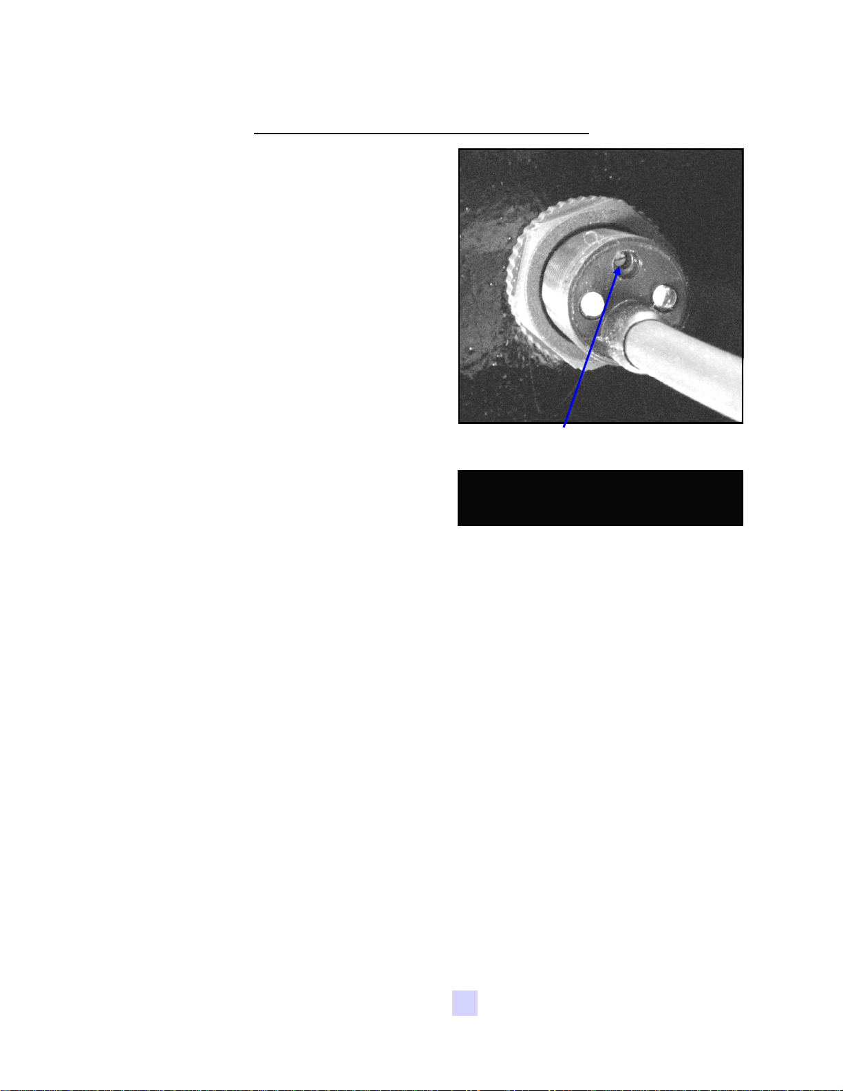
Sensitivity Adjustment Screw
Proximity Switch Screwdriver
Using the small screwdriver provided inside the control panel, you can adjust the
proximity switch by turning the adjusting screw on the back of the proximity switch.
Turn Clockwise to make the proximity switch more sensitive.
Turn Counterclockwise to make the proximity switch less sensitive.
USC, LLCPage 40
Page 41
LPX MANUAL SEED TREATER
Section
Section
Maintenance
Maintenance
Proper maintenance of the USC LPX Manual Seed Treater is critical for peak
performance, reliability and accuracy of this system. The following is a guideline for
the type of maintenance and servicing that should be performed on this unit. Your
environment and uses may require additional maintenance and service beyond this
list to assure a reliable and safe unit. The operator of this unit has ultimate
responsibility to identify areas of concern and rectify them before they become a
hazard or safety issue. There is no substitute for a trained, alert operator.
Do not put this unit into operation with any questionably
maintained parts. Poor performance or a hazard may occur.
DRIVE AND DRUM
Inspect all welds and structural components on frame
Check drum for bends, cracks and damage.
GG
Remove shields to inspect bearings and tighten set screws.
Inspect drive wheels for unordinary wear, and set screws for tightness.
Inspect and adjust the Neoprene guide wheels located near back of drum.
Tighten and lubricate chains.
Inspect and re-align sprockets.
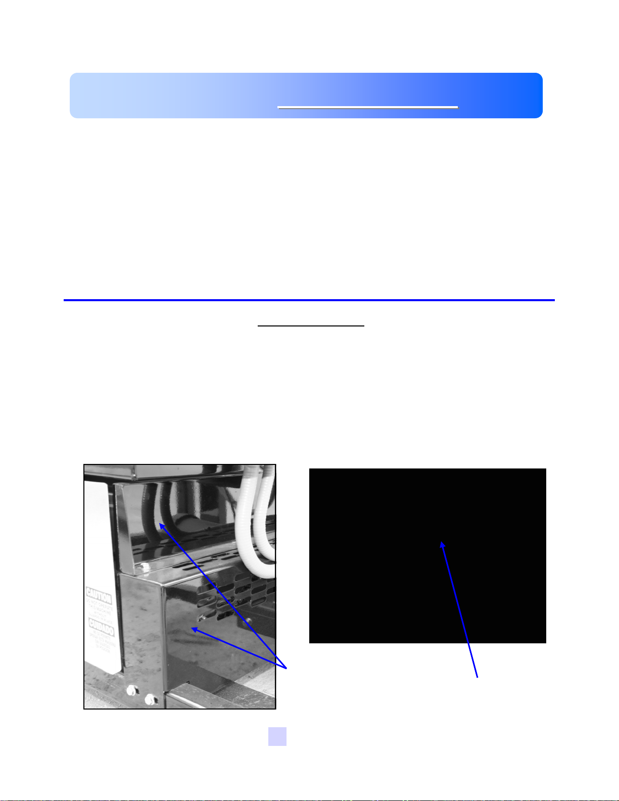
Remove these two
guards to access
chains
Use this sprocket to
tighten chain
USC, LLC Page 41
Page 42
LPX MANUAL SEED TREATER
ATOMIZER
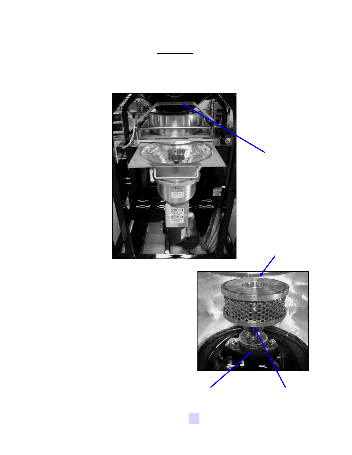
To access inside of atomizer housing, push up on the quick release handle and
slide back the atomizer (see picture below).
Quick-Release
Handle
Slide back atomizer housing and grease
bearing inside. Bearing needs just one
pump of grease every 40 hours of use.
Clean any build-up inside the housing and
the atomizer head. To remove the
atomizer head, loosen the set screw
located on the bottom of the head.
Check for any play in the atomizer shaft.
Make sure the atomizer spins smoothly.
Ensure the adjustable chute is fitting
completely into the drum opening. Adjust
if necessary.
Bearing
Atomizer Head
Set Screw
USC, LLCPage 42
Page 43

LPX MANUAL SEED TREATER
PUMPS AND PLUMBING
Check pump in forward and reverse.
Check and adjust pump voltage
Inspect brushes in motors.
Make sure pump head(s) opens and closes smoothly.
Inspect tubing and valves.
Tighten hose clamps and check/clean filter.
MIX TANK
Check motor.
Check for any play in the mix tank shaft.
Check valves, fittings, and plug on bottom of tank.
CONTROL PANEL
Check and tighten wire connections.
Check starters and overloads.
Check timers and relays.
Check the front of the panel; switches, voltmeter, potentiometer, etc.
Inspect fuses and breakers.
Check and set the proximity switches.
USC, LLC Page 43
Page 44

LPX MANUAL SEED TREATER
Section
Section
Storage
Storage
When storing the USC LPX Manual Seed Treater for long periods of time, the
following procedure must be followed to reduce the chance of rust, corrosion and
fatigue of the treater. You can also use these steps when storing the machine for
the winter.
A dust mask and protective rubber gloves shall be used when
cleaning the machine.
SUPPLY HOPPER
1. Clean out the supply hopper of any debris (compressed air can be used).
HH
2. Wipe the proximity switches clean.
3. Tarp or cover the hopper to keep out any unwanted pests.
ATOMIZER CHAMBER
1. Remove and clean the atomizer housing.
2. Remove the atomizer head and stainless steel plumbing. The atomizer head
can be disassembled (below), for easier cleaning. It is threaded together and
can simply be unscrewed.
3. Reinstall the atomizer head and plumbing. Grease the bearing and spin the
atomizer head a few times to ensure all grease has been worked into the
bearings.
USC, LLCPage 44
Page 45

LPX MANUAL SEED TREATER
ROTATING DRUM
1. Remove the shields and clean out any seed that may have fallen underneath the
drum.
2. Lubricate the chain to keep from corroding in storage.
LIQUID SYSTEM
1. Make certain the inside of the tank is completely drained of chemical residue and
thoroughly flush the inside of the tank with clean water.
2. Remove and clean the filter.
3. Pump clean water through all areas of the plumbing including the mix tank,
calibration tube, and valves.
4. Open all drain points, valves, and filter to let as much of the liquid drain as
possible.
5. If the seed treater will be exposed to possible
freezing temperatures, the final flush of the system
should be made with an non freezable liquid. Or
use compressed air to blow the lines out from any
moisture.
6. Release pump head (right) and remove tubing to
prevent any unnecessary wear.
FINAL
1. Store the machine inside a protective building to keep it from being exposed to
the weather.
2. Disconnect power to the machine.
USC, LLC Page 45
Page 46

LPX MANUAL SEED TREATER
Section
Section
Mechanical Drawings
Mechanical Drawings
The following pages show the parts of the LPX Manual Seed Treater. Please have the
part number ready when ordering parts.
II
Item Page #
Mechanical Drawings & Parts List ............................................................................... 47
Limited Warranty Information ...................................................................................... 89
USC, LLCPage 46
Page 47

LPX MANUAL SEED TREATER
LPX Base Frame Assembly
USC, LLC Page 47
Page 48

LPX MANUAL SEED TREATER
LPX Base Frame Assembly
USC, LLCPage 48
Page 49

LPX MANUAL SEED TREATER
LPX Base Frame Assembly
USC, LLC Page 49
Page 50

LPX MANUAL SEED TREATER
LPX Base Frame Assembly Parts List
LPX BASE FRAME ASSEMBLY
LPX 6FT LPX 8FT LPX 10FT
18-01-0011 18-01-0012 18-01-0013
Item # Title Part # Qty Part # Qty Part # Qty
1 GBOX IL 56C 16.2:1 GR B1 FOOT MNT 01-01-0101 1 01-01-0101 1 01-01-0101 1
2
SPROCKET # 50 14T 1.00 IN BORE
TYPE B
01-02-0093 4 01-02-0093 4 01-02-0093 4
3 SPKT 17 T 50P .500 ID IDLER 01-02-0095 2 01-02-0095 2 01-02-0095 2
4 BRG PLW 1.00ID STSC SEALED 01-03-0036 6 01-03-0036 6 01-03-0036 6
5 #50 CNTG LINK 01-04-0005 2 01-04-0005 2 01-04-0005 2
6 SHAFT CLR 1.00ID SPLIT 01-05-0008 8 01-05-0008 8 01-05-0008 8
7 WHL DRV 6 X 2 X 1.00ID .250KWY 01-06-0002 4 01-06-0002 4 01-06-0002 4
8 KEY .250 X 2.00 CS 01-10-0003 4 01-10-0003 4 01-10-0003 4
9 KEY .250 X 1.00 CS 01-10-0004 4 01-10-0004 4 01-10-0004 4
10 WDMT DRUM DRV ADJ PLT 05-04-0067 1 05-04-0067 1 05-04-0067 1
11 DRIVE SHAFT 05-11-0003 2 05-11-0348 2 05-11-0235 2
12 BOLT CRG .500-13 X 2.00 ZP GR5 06-01-0026 1 06-01-0026 1 06-01-0026 1
13 BOLT .500-13 X 2.00 ZP GR5 06-01-0027 1 06-01-0027 1 06-01-0027 1
14 BOLT .500-13 X 3.25 ZP GR5 06-01-0029 12 06-01-0029 12 06-01-0029 12
15
BOLT .375-16 X 2.00 ZP GR5 FULL
THRD
06-01-0137 2 06-01-0137 2 06-01-0137 2
16 BOLT CRG .313-18 X 1.75 ZP GR5 06-01-0172 4 06-01-0172 4 06-01-0172 4
17 NUT FULL .375-16 ZP GR5 06-02-0003 2 06-02-0003 2 06-02-0003 2
18 NUT LOCK FLG .500-13 ZP GR5 06-03-0015 14 06-03-0015 14 06-03-0015 14
19 NUT, FLG .3125-18 UNC ZP GRADE 5 06-03-0019 4 06-03-0019 4 06-03-0019 4
20 #50 CHAIN 84LINKS 13-05-0156 1 13-05-0156 1 13-05-0156 1
21 #50 CHAIN -- 32 LINKS 13-05-0157 1 13-05-0157 1 13-05-0157 1
22 WDMT BASE FR LPX 18-01-0007 1 18-01-0008 1 18-01-0009 1
USC, LLCPage 50
Page 51

LPX MANUAL SEED TREATER
LPX Drum Assembly
USC, LLC Page 51
Page 52
LPX MANUAL SEED TREATER
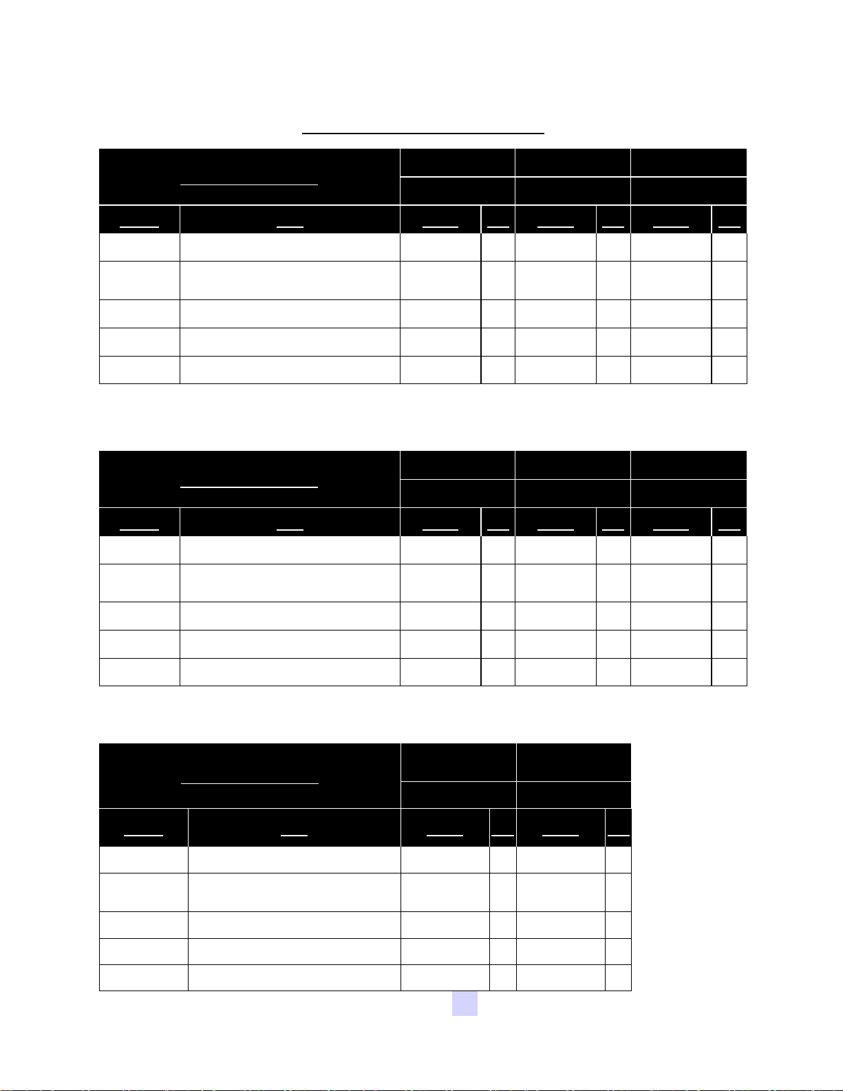
LPX Drum Assembly Parts List
LPX800 6FT CS LPX800 6FT SS LPX2000 6FT CS
LPX DRUM ASSEMBLY
18-01-0042 18-01-0043 18-01-0044
Item # Title Part # Qty Part # Qty Part # Qty
1 NUT LOCK FLG .375-16 ZP GR5 06-03-0014 24 06-03-0014 24 06-03-0014 24
2 WSHR SS BONDED SEALING .375 ID 06-04-0013 24 06-04-0013 24 06-04-0013 24
3 WDMT DRUM LPX 18-01-0016 1 18-01-0129 1 18-01-0018 1
4 WDMT DRUM PDL TALL 18-01-0026 4 18-01-0027 4 18-01-0026 4
5 WDMT DRUM PDL SHORT 18-01-0034 4 18-01-0035 4 18-01-0034 4
LPX2000 6FT SS LPX2000 8FT CS LPX2000 8FT SS
LPX DRUM ASSEMBLY
18-01-0045 18-01-0046 18-01-0047
Item # Title Part # Qty Part # Qty Part # Qty
1 NUT LOCK FLG .375-16 ZP GR5 06-03-0014 24 06-03-0014 32 06-03-0014 32
2 WSHR SS BONDED SEALING .375 ID 06-04-0013 24 06-04-0013 32 06-04-0013 32
3 WDMT DRUM LPX 18-01-0019 1 18-01-0020 1 18-01-0132 1
4 WDMT DRUM PDL TALL 18-01-0027 4 18-01-0028 4 18-01-0133 4
5 WDMT DRUM PDL SHORT 18-01-0035 4 18-01-0036 4 18-01-0134 4
LPX2000 10FT CS LPX2000 10FT SS
LPX DRUM ASSEMBLY
18-01-0048 18-01-0049
Item # Title Part # Qty Part # Qty
1 NUT LOCK FLG .375-16 ZP GR5 06-03-0014 40 06-03-0014 40
2
WSHR SS BONDED SEALING .375
ID
06-04-0013 40 06-04-0013 40
3 WDMT DRUM LPX 18-01-0022 1 18-01-0135 1
4 WDMT DRUM PDL TALL 18-01-0030 4 18-01-0136 4
5 WDMT DRUM PDL SHORT 18-01-0038 4 18-01-0137 4
USC, LLCPage 52
Page 53

LPX MANUAL SEED TREATER
LPX End Chute & Parts List
LPX END CHUTE 18-01-0072
Item # Part # Title Qty
1 05-10-3400 PLT DSCHG TRTR 4
2 05-10-3886 SKIRT DSCHG TRTR LPX2000 1
3 06-01-0198 BOLT, CARRIAGE, 5/16-18 X 3/4 UNC ZP GRADE 5 12
4 06-03-0002 NUT NYL LOCK .313-18 ZP GR5 12
5 101FB5 ADPT END CHUTE EXT LPX2000 1
USC, LLC Page 53
Page 54

LPX MANUAL SEED TREATER
LPX Static Mixer & Parts List
LPX STATIC MIXER 04-03-0157
Item # PART # Title Qty
1 02-02-0006 VLV BALL .500 NPT 2WAY BRSS 5
2 02-05-0005 FTTG CPLG .500 NPT FM SS 1
3 02-06-0020 FTTG 90 DEG STRT .500NPTX .500NPT 4
4 02-07-0007 FTTG NIP .500 NPT X 1.125 TBE SS 5
5 02-07-0019 NIPPLE, .500-14 NPT X 3.0 LG 304SS 1
6 02-08-0007 FTTG STGHT .500HB X .500NPT ML NYL 1
7 02-11-0001 FTTG CROSS .500 NPT FM SS 2
8 02-15-0014 FTTG CPLG .500 NPT QCK DISC INSERT 4
9 02-16-0050 FTTG PUSH 90DEG .625ODX.500 NPT ML 1
10 04-03-0030 MXR IL PVC 6ELEMENT .500PIPE X 7.00 1
11 05-10-2891B STATIC MIXER & MNFLD MNT BRKT 1
12 06-01-0037 BOLT U .313-18 X 1.38 X 2.188 ZP 2
13 06-03-0002 NUT NYL LOCK .313-18 ZP GR5 4
USC, LLCPage 54
Page 55

LPX MANUAL SEED TREATER
LPX Treater
USC, LLC Page 55
Page 56

LPX MANUAL SEED TREATER
LPX Treater
USC, LLCPage 56
Page 57

LPX MANUAL SEED TREATER
LPX Treater
USC, LLC Page 57
Page 58

LPX MANUAL SEED TREATER
LPX Treater
USC, LLCPage 58
Page 59

LPX MANUAL SEED TREATER
LPX Treater
USC, LLC Page 59
Page 60

LPX MANUAL SEED TREATER
LPX Treater
USC, LLCPage 60
Page 61

LPX MANUAL SEED TREATER
LPX Treater
USC, LLC Page 61
Page 62

LPX MANUAL SEED TREATER
LPX Treater Parts List
LPX TREATER 800 - 6 Foot 2000 - 6 Foot
Item #
1
CNVR CNTL PANEL See Table 1a 1 See Table 1a 1
Title Part # Qty Part # Qty
2 WHL GUIDE .375ID X 2.50 X .875 NPRN 01-06-0004 2 01-06-0004 2
3 SMW PANEL See Table 1b 1 See Table 1b 1
4 TRTR PANEL See Table 1c 1 See Table 1c 1
5 KIT PWR See Table 2a 1 See Table 2a 1
6 ASSY STTC MXR & VLVS LPX TRTR 04-03-0157 1 04-03-0157 1
7 WDMT ADJ TREATER LEG 05-05-0001 4 05-05-0001 4
8 WDMT CHAIN GRD LP800/LP2000 05-06-0001 1 05-06-0001 1
9 WDMT INLET HOPP EXT See Table 3a 1 See Table 3a 1
10 ASSY END CHUTE DOOR GALV 05-07-0198 1 05-07-0198 1
11 GRD DRUM INLET LOWER 05-10-0150 1 05-10-0150 1
12 PLT CVR DISCH CHUTE 1 05-10-3800 1 05-10-3800 1
13 GRD DRUM INLET LPX BOLTED 05-10-3931 1 05-10-3931 1
14 GRD DRUM BTM FRNT HALF LPX 05-10-3950 1 05-10-3950 1
15 GRD DRUM BTM REAR HALF LPX 05-10-3951 1 05-10-3951 1
16 SEED WHEEL PANEL MOUNT PLATE 05-10-3980 1 05-10-3980 1
17 BOLT .250-20 X .750 ZP GR5 06-01-0006 12 06-01-0006 12
18 BOLT .375-16 X 1.75 ZP GR5 06-01-0019 2 06-01-0019 2
19 BOLT .500-13 X .750 ZP GR5 06-01-0024 4 06-01-0024 4
20 BOLT .500-13 X 3.25 ZP GR5 06-01-0029 8 06-01-0029 8
21 BOLT, FLG .375-16 UNC ZP GRADE 5; 3/4" LG 06-01-0124 76 06-01-0124 76
22 BOLT, CARRIAGE, 5/16-18 X 3/4 UNC ZP GRADE 5 06-01-0198 4 06-01-0198 4
23 BOLT FLG .500-13 X 1.250 ZP GR5 06-01-0232 4 06-01-0232 4
24 NUT,LOCK, FLG .250-20 ZP SERRATTED 06-03-0013 4 06-03-0013 4
25 NUT LOCK FLG .375-16 ZP GR5 06-03-0014 12 06-03-0014 12
26 NUT LOCK FLG .500-13 ZP GR5 06-03-0015 12 06-03-0015 12
27 NUT LOCK FLG .3125-18 ZP GR5 06-03-0019 4 06-03-0019 4
USC, LLCPage 62
Page 63

LPX MANUAL SEED TREATER
LPX Treater Parts List
LPX TREATER 800 - 6 Foot 2000 - 6 Foot
Item # Title Part # Qty Part # Qty
28 WSHR LOCK SPLT .250 ZP 06-04-0001 8 06-04-0001 8
29 WSHR FLAT .500 ZP 06-05-0005 8 06-05-0005 8
30 PIN CLIP HITCH 3.063 SIZE 9 ZP 06-09-0002 4 06-09-0002 4
31 PIN CLVS .500 X 3.50 PLN 06-09-0005 4 06-09-0005 4
32 SEAL BRSH 180 DEG 7.81 OR X 4.00 IR 06-10-0018 2 06-10-0018 2
33 ATWL LBL USC, LLC 3" X 15" PRO-CUT 09-01-0042 1 09-01-0042 1
34 ASSY SEED METER WHL 13-04-0064 1 13-04-0065 1
35 ASSY BASE FR LPX 18-01-0011 1 18-01-0011 1
36 ASSY DRUM LPX2000 18-01-0042 1 18-01-0044 1
36* ASSY DRUM LPX2000 (Stainless Steel Only) 18-01-0043 1 18-01-0045 1
37 WDMT DRUM GRD LPX 18-01-0050 1 18-01-0050 1
38 WDMT DRUM EXT GRD LPX 6-8-10FT 18-01-0054 1 18-01-0054 1
39 WDMT END CHUTE LPX 18-01-0057 1 18-01-0057 1
39* WDMT END CHUTE LPX (Stainless Steel Only) 18-01-0125 1 18-01-0125 1
40 ASSY ADJ CHMBR LPX 18-01-0061 1 18-01-0062 1
41 ASSY ATMZR 18-01-0067 1 18-01-0069 1
41* ASSY ATMZR (Stainless Steel Only) 18-01-0068 1 18-01-0070 1
42 ASSY END CHUTE EXT LPX 18-01-0072 1 18-01-0072 1
43 WDMT INLET HOPP LPX 18-01-0080 1 18-01-0080 1
44 WDMT HEADACHE RACK SHORT 18-01-0081 1 18-01-0081 1
45 WDMT DRUM EXT GRD MNT LPX 6-8-10FT 18-01-0082 1 18-01-0082 1
46 WDMT HEADACHE RACK TALL 18-01-0083 1 18-01-0083 1
47 ASSY GRD DRUM LPX2000 RT GALV 18-01-0091 1 18-01-0091 1
48 ASSY GRD DRUM LPX2000 LT GALV 18-01-0094 1 18-01-0094 1
49 WDMT ENCL MNT LPX 18-01-0097 1 18-01-0097 1
50 WDMT FORKLIFT PCKT EXT 18-01-0106 2 18-01-0106 2
USC, LLC Page 63
Page 64

LPX MANUAL SEED TREATER
LPX Treater Parts List
LPX TREATER 2000 - 8 Foot 2000 - 10 Foot
Item #
1
2
3
4
5
6
7
8
9
10
11
12
13
14
15
16
17
18
19
20
21
22
23
24
25
26
27
Title Part #
Qt
y
Part # Qty
CNVR CNTL PANEL See Table 1a 1 See Table 1a 1
WHL GUIDE .375ID X 2.50 X .875 NPRN 01-06-0004 2 01-06-0004 2
SMW PANEL See Table 1b 1 See Table 1b 1
TRTR PANEL See Table 1c 1 See Table 1c 1
KIT PWR See Table 2a 1 See Table 2a 1
ASSY STTC MXR & VLVS LPX TRTR 04-03-0157 1 04-03-0157 1
WDMT ADJ TREATER LEG 05-05-0001 4 05-05-0001 4
WDMT CHAIN GRD LP800/LP2000 05-06-0001 1 05-06-0001 1
WDMT INLET HOPP EXT See Table 3a 1 See Table 3a 1
ASSY END CHUTE DOOR GALV 05-07-0198 1 05-07-0198 1
GRD DRUM INLET LOWER 05-10-0150 1 05-10-0150 1
PLT CVR DISCH CHUTE 1 05-10-3800 1 05-10-3800 1
GRD DRUM INLET LPX BOLTED 05-10-3931 1 05-10-3931 1
GRD DRUM BTM FRNT HALF LPX 05-10-3993 1 05-10-3923 1
GRD DRUM BTM REAR HALF LPX 05-10-3994 1 05-10-3924 1
SEED WHEEL PANEL MOUNT PLATE 05-10-3980 1 05-10-3980 1
BOLT .250-20 X .750 ZP GR5 06-01-0006 12 06-01-0006 12
BOLT .375-16 X 1.75 ZP GR5 06-01-0019 2 06-01-0019 2
BOLT .500-13 X .750 ZP GR5 06-01-0024 4 06-01-0024 4
BOLT .500-13 X 3.25 ZP GR5 06-01-0029 8 06-01-0029 8
BOLT, FLG .375-16 UNC ZP GRADE 5; 3/4" LG 06-01-0124 76 06-01-0124 76
BOLT, CARRIAGE, 5/16-18 X 3/4 UNC ZP GRADE 5 06-01-0198 4 06-01-0198 4
BOLT FLG .500-13 X 1.250 ZP GR5 06-01-0232 4 06-01-0232 4
NUT,LOCK, FLG .250-20 ZP SERRATTED 06-03-0013 4 06-03-0013 4
NUT LOCK FLG .375-16 ZP GR5 06-03-0014 12 06-03-0014 12
NUT LOCK FLG .500-13 ZP GR5 06-03-0015 12 06-03-0015 12
NUT LOCK FLG .3125-18 ZP GR5 06-03-0019 4 06-03-0019 4
USC, LLCPage 64
Page 65

LPX MANUAL SEED TREATER
LPX Treater Parts List
LPX TREATER 2000 - 8 Foot 2000 - 10 Foot
Item # Title Part #
28
29
30
31
32
33
34
35
36
36*
37
38
39
39*
40
41
41*
42
43
44
45
46
47
48
49
50
WSHR LOCK SPLT .250 ZP 06-04-0001 8 06-04-0001 8
WSHR FLAT .500 ZP 06-05-0005 8 06-05-0005 8
PIN CLIP HITCH 3.063 SIZE 9 ZP 06-09-0002 4 06-09-0002 4
PIN CLVS .500 X 3.50 PLN 06-09-0005 4 06-09-0005 4
SEAL BRSH 180 DEG 7.81 OR X 4.00 IR 06-10-0018 2 06-10-0018 2
ATWL LBL USC, LLC 3" X 15" PRO-CUT 09-01-0042 1 09-01-0042 1
ASSY SEED METER WHL 13-04-0065 1 13-04-0065 1
ASSY BASE FR LPX 18-01-0012 1 18-01-0013 1
ASSY DRUM LPX2000 18-01-0046 1 18-01-0048 1
ASSY DRUM LPX2000 (Stainless Steel Only) 18-01-0047 1 18-01-0049 1
WDMT DRUM GRD LPX 18-01-0051 1 18-01-0052 1
WDMT DRUM EXT GRD LPX 6-8-10FT 18-01-0054 1 18-01-0054 1
WDMT END CHUTE LPX 18-01-0057 1 18-01-0057 1
WDMT END CHUTE LPX (Stainless Steel Only) 18-01-0125 1 18-01-0125 1
ASSY ADJ CHMBR LPX 18-01-0062 1 18-01-0062 1
ASSY ATMZR 18-01-0069 1 18-01-0069 1
ASSY ATMZR (Stainless Steel Only) 18-01-0070 1 18-01-0070 1
ASSY END CHUTE EXT LPX 18-01-0072 1 18-01-0072 1
WDMT INLET HOPP LPX 18-01-0080 1 18-01-0080 1
WDMT HEADACHE RACK SHORT 18-01-0081 1 18-01-0081 1
WDMT DRUM EXT GRD MNT LPX 6-8-10FT 18-01-0082 1 18-01-0082 1
WDMT HEADACHE RACK TALL 18-01-0083 1 18-01-0083 1
ASSY GRD DRUM LPX2000 RT GALV 18-01-0092 1 18-01-0093 1
ASSY GRD DRUM LPX2000 LT GALV 18-01-0095 1 18-01-0096 1
WDMT ENCL MNT LPX 18-01-0097 1 18-01-0097 1
WDMT FORKLIFT PCKT EXT 18-01-0107 2 NA
Qt
y
Part # Qty
USC, LLC Page 65
Page 66

LPX MANUAL SEED TREATER
LPX Treater Parts List
Table 1a -> CNVR PNL
03-12-0152 -> PNL CNVR 230V 1PH 5HP IN 5HP OUT
03-12-0153 -> PNL CNVR 230V 1PH 7.5HP IN 5HP OUT
03-12-0154 -> PNL CNVR 230V 1PH 5HP IN 7.5HP OUT
03-12-0155 -> PNL CNVR 230V 1PH 7.5HP IN 7.5HPOUT
03-12-0156 -> PNL CNVR 230V 3PH 5HP IN 5HP OUT
03-12-0157 -> PNL CNVR 230V 3PH 7.5HP IN 5HP OUT
03-12-0158 -> PNL CNVR 230V 3PH 5HP IN 7.5HP OUT
03-12-0159 -> PNL CNVR 230V 3PH 7.5HP IN 7.5HPOUT
03-12-0160 -> PNL CNVR 460V 3PH 5HP IN 5HP OUT
03-12-0161 -> PNL CNVR 460V 3PH 7.5HP IN 5HP OUT
03-12-0162 -> PNL CNVR 460V 3PH 5HP IN 7.5HP OUT
03-12-0163 -> PNL CNVR 460V 3PH 7.5HP IN 7.5HPOUT
03-12-0164 -> PNL CNVR 575V 3PH 5HP IN 5HP OUT
03-12-0165 -> PNL CNVR 575V 3PH 7.5HP IN 5HP OUT
03-12-0166 -> PNL CNVR 575V 3PH 5HP IN 7.5HP OUT
03-12-0167 -> PNL CNVR 575V 3PH 7.5HP IN 7.5HP OUT
Table 1b -> SMW PNL
03-12-0172 -> PNL CNTL LPX SMW 230V 1PH
03-12-0173 -> PNL CNTL LPX SMW 230V 3PH
03-12-0174 -> PNL CNTL LPX SMW 460V 3PH
03-12-0175 -> PNL CNTL LPX SMW 575V 3PH
03-12-0176 -> PNL CNTL LPX MNL SMW (This is the 2nd Seed Wheel panel for the manual
option only)
Table 1c -> TRTR PNL
03-12-0168 -> PNL CNTL LPX TRTR 230V 1PH
03-12-0169 -> PNL CNTL LPX TRTR 230V 3PH
03-12-0170 -> PNL CNTL LPX TRTR 460V 3PH
03-12-0171 -> PNL CNTL LPX TRTR 575V 3PH
Table 2a -> Power Kits
230V -> 03-20-0011
575V -> 03-20-0017
Table 3a -> Extension Rings
0
6IN CS -> 05-07-0367
12IN CS -> 05-07-0008
USC, LLCPage 66
Page 67

LPX MANUAL SEED TREATER
LPX Pump Stand - Single Pump Head & Parts List
SINGLE PUMP HEAD 13-04-0105
Item # Part # Title Qty
1 01-01-0010 MTR .1HP 6-600RPM 90VDC 1
2 02-01-0005 PUMP HEAD PRST MF LS 115V 600RPM 1
3 02-03-0001 TUBE MASTERFLEX PUMPHEAD (28 inches) 4
4 02-14-0002 1/2-14 NPT,PLUG BP 4
5 02-15-0016 FTTG CPLG .500 NPT QCK DISC BODY 2
6 02-15-0022 FTTG CPLG .375 HB X 90 QCK DISC INSERT 2
7 06-01-0189 BOLT, FLG .375-16 UNC ZP GRADE 5; 1-1/4" LG 2
8 06-03-0014 NUT LOCK FLG .375-16 ZP GR5 2
9 06-07-0005 CLMP HOSE .219 TO .625 X .313W ZP 2
10 102276 BRKT PUMP MOUNT PUMPSTD 1
USC, LLC Page 67
Page 68
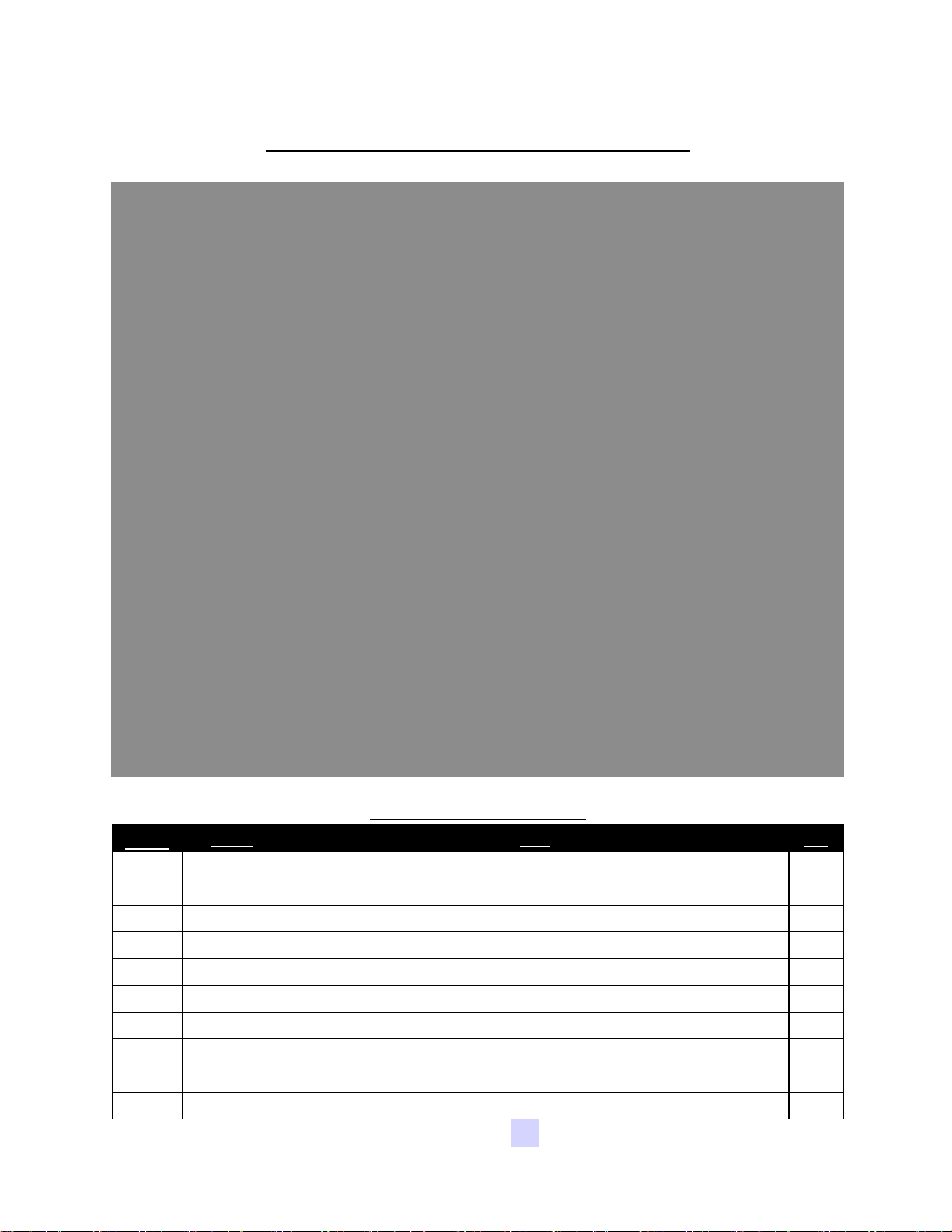
LPX MANUAL SEED TREATER
LPX Pump Stand - Dual Pump Head & Parts List
DUAL PUMP HEAD 13-04-0104
Item #
Part # Title Qty
1 01-01-0010 MTR .1HP 6-600RPM 90VDC 1
2 02-01-0005 PUMP HEAD PRST MF LS 115V 600RPM 2
3 02-03-0001 TUBE MASTERFLEX PUMPHEAD (28 Inches) 5
4 02-14-0002 1/2-14 NPT,PLUG BP 2
5 02-15-0016 FTTG CPLG .500 NPT QCK DISC BODY 4
6 02-15-0022 FTTG CPLG .375 HB X 90 QCK DISC INSERT 4
7 06-01-0189 BOLT, FLG .375-16 UNC ZP GRADE 5; 1-1/4" LG 2
8 06-03-0014 NUT LOCK FLG .375-16 ZP GR5 2
9 06-07-0005 CLMP HOSE .219 TO .625 X .313W ZP 4
10 102276 BRKT PUMP MOUNT PUMPSTD 1
USC, LLCPage 68
Page 69

LPX MANUAL SEED TREATER
LPX Pump Stand - Triple Pump Head & Parts List
3 PUMP HEAD 13-04-0103
Item # Part # Title Qty
1 01-01-0066 SPEED REDUCER, 3.7 TO 1 1
2 01-01-0160 MTR .25HP 2500 RPM 34 90VDC 1
3 02-01-0005 PUMP HEAD PRST MF LS 115V 600RPM 3
4 02-15-0016 FTTG CPLG .500 NPT QCK DISC BODY 6
5 02-15-0022 FTTG CPLG .375 HB X 90 QCK DISC INSERT 6
6 06-01-0124 BOLT, FLG .375-16 UNC ZP GRADE 5; 3/4" LG 6
7 06-01-0137 BOLT .375-16 X 2.00 ZP GR5 FULL THRD 2
8 06-03-0014 NUT LOCK FLG .375-16 ZP GR5 8
9 06-07-0005 CLMP HOSE .219 TO .625 X .313W ZP 6
10 102213 BRKT 3PUMPHEAD MNT PUMPSTD 1
11 102214 BRKT 3HEAD MOTOR MNT PUMPSTD 1
12 02-03-0001 HOSE MF .375 NPRN BLK - LS35 .31 ID (28 Inches) 6
USC, LLC Page 69
Page 70
LPX MANUAL SEED TREATER
LPX Pump Stand - Calibration Tube & Parts List
CAL TUBE PUMP STAND 13-04-0106
Item # Part # Title Qty
1 02-03-0005 TUBE,CALIBRATION TUBE INSIDE (22.5 Inches)
1
2 02-03-0034 TUBE CAL TUBE TO VLV PUMPSTD (11.25 Inches) 1
3 02-03-0034 TUBE SOL VLV TO CAL TUBE PUMPSTD (28 Inches) 1
4 02-04-0008 BUSHING .750-14 NPT, REDUCER .500-14 NPT 1
5 02-08-0007 FTTG STGHT .500HB X .500NPT ML NYL 1
6 02-16-0028 FTTG PUSH .625OD X .500 NPT ML 2
7 02-16-0050 FTTG PUSH 90DEG .625ODX.500 NPT ML 1
8 05-08-0006 WDMT,INOC.BRK,SM 1
9 05-08-0007 WDMT,BRK,INOC LG 1
10 06-01-0189 BOLT, FLG .375-16 UNC ZP GRADE 5; 1-1/4" LG 1
11 06-03-0003 NUT NYL LOCK .375-16 ZP GR5 1
12 06-05-0004 WSHR FLAT .375 ZP 2
13 06-07-0006 CLMP HOSE .500 TO .906 X .313W ZP 1
14 07-02-0006 CALIBRATION TUBE,10K ML - 2005 1
USC, LLCPage 70
Page 71

LPX MANUAL SEED TREATER
LPX Pump Stand - Dry Lock Fittings & Parts List
DRY LOCK FITTINGS 13-10-0017
Item # Part # Title Qty
1 02-04-0024 BUSH .750-14 NPT .500-14 NPT BP 1
2 02-06-0017 1/2-14 NPT,SL 90 DEG. BP 1
3 02-07-0009 FTTG NIP .500 NPT X 1.75 TBE BLK 1
4 02-15-0035 FTTG CPLG 0.50 NPT FM PARKER POLY 1
5 02-15-0036 FTTG CPLG 0.50 NPT ML PARKER POLY 1
USC, LLC Page 71
Page 72

LPX MANUAL SEED TREATER
LPX Pump Stand - Base Frame
USC, LLCPage 72
Page 73

LPX MANUAL SEED TREATER
LPX Pump Stand - Base Frame Parts List
LPX PUMP STAND BASE FRAME 05-03-1066
Item # Part # Title Qty
1 02-02-0007 VLV BALL .500 NPT 3WAY BRSS 1
2 02-04-0008 BUSHING .750-14 NPT, REDUCER .500-14 NPT 1
3 02-05-0043 FTTG MANIFOLD UHMW 1 IN 3 OUT 2
4 02-06-0015 BARB, .750-14 NPT X .750 90DEG WP 1
5 02-07-0070 FTTG NIP .750 NPT X 1.50 TBE SS 1
6 02-08-0011 1/2-14 NPT, 3/4 BARB, STRAIGHT BP 1
7 02-12-0011 FLTR TEE PPE .750 NPT 16 MESH BANJO 1
8 02-16-0028 FTTG PUSH .625OD X .500 NPT ML 1
9 02-16-0050 FTTG PUSH 90DEG .625ODX.500 NPT ML 1
10 05-03-1052 WDMT SMALL PUMPSTAND LH UPRIGHT 1
11 05-03-1053 WDMT SMALL PUMPSTAND BASE BOX 1
12 05-03-1064 WDMT PANEL MNT PUMPSTD 1
13 05-03-1072 WDMT SPACER PUMPSTD 1
14 05-03-1073 WDMT SCALE LID PUMPSTD 1
15 05-03-1074 WDMT SMALL PUMPSTAND RH UPRIGHT 1
16 06-01-0124 BOLT, FLG .375-16 UNC ZP GRADE 5; 3/4" LG 31
17 06-01-0192 BOLT .250-20 X 2.50 ZP GR5 8
18 06-03-0013 NUT,LOCK, FLG .250-20 ZP SERRATTED 8
19 06-03-0014 NUT LOCK FLG .375-16 ZP GR5 1
20 06-06-0020 SRCW, PAN HD, 10-24 X .500 ZP 2
21 06-07-0007 CLMP HOSE .563 TO 1.06 X .313W ZP 2
22 102200 BRKT PUMP ALL HEADS PUMPSTD 1
23 10220E PLT XBEAM SUPP VLV PUMPSTD 1
24 102290 PLT LABEL SOURCE PUMPSTD 1
25 1022AA BRKT FORKLIFT GUARD PUMPSTD 1
26 1022AB 1022AB 02-03-0006 8.25IN LONG 1
27 1022AC PLT SPACER VLV SOURCE MOUNT 1
USC, LLC Page 73
Page 74

LPX MANUAL SEED TREATER
LPX Pump Stand - Scale Assembly & Parts List
LPX SCALE ASSY 05-03-1069
Item # Part # Title Qty
1 03-19-0028 SCL, 24' X 24" 1000 LB BASE 1
2 06-01-0204 BOLT, FLG .375-16 UNC ZP GRADE 5; 2-1/2" LG 1
3 06-03-0014 NUT LOCK FLG .375-16 ZP GR5 2
4 06-03-0015 NUT LOCK FLG .500-13 ZP GR5 12
5 06-05-0004 WSHR FLAT .375 ZP 2
6 06-14-0018 .500-13 THD RD CS 3IN LONG 4
7 PART OF 03-19-0028 SCALE DISPLAY 1
USC, LLCPage 74
Page 75
LPX MANUAL SEED TREATER
LPX Pump Stand - Mass Flow Meter & Parts List
MASS FLOW METER 05-03-1067
Item # Part # Title Qty
1 02-03-0034 TUBE MANIFOLD TO FLOWMETER (14.75 Inches) 1
2 02-03-0034 TUBE FLOWMETER TO SOLENOID VALVE (20 Inches) 1
3 02-16-0050 FTTG PUSH 90DEG .625ODX.500 NPT ML 2
4 03-18-0019 FLMT PROMASS 83E08 DN8 3/8IN 1
5 03-18-0021 FTTG ADPTR 1/2" VC0 X 1/2" FPT E+H 2
6 05-10-3413 BRACKET FLMT CLAMP E&H 83E 1
7 06-01-0116 BOLT .375-16 X 2.75 ZP GR5 2
USC, LLC Page 75
Page 76
LPX MANUAL SEED TREATER
LPX Pump Stand - Volumetric Flow Meter & Parts List
VOLUMETRIC FLOW METER 05-03-1068
Item # Part # Title Qty
1 02-03-0034 TUBE MANIFOLD TO FLOWMETER (31 Inches) 1
2 02-03-0034 TUBE FLOWMETER TO AUTO VLV (22 Inches) 1
3 02-05-0005 FTTG CPLG .500 NPT FM SS 2
4 02-16-0028 FTTG PUSH .625OD X .500 NPT ML 1
5 02-16-0050 FTTG PUSH 90DEG .625ODX.500 NPT ML 1
6 03-18-0018 FLMT IFM EFECTOR SM6001 1/2 IN 1
7 03-18-0020 FTTG ADPTR G1/2 TO 1/2NPT ML IFM 2
8 06-01-0199 BOLT U .313-18 X 1.00 X .375 ZP GR5 2
9 06-03-0013 NUT,LOCK, FLG .250-20 ZP SERRATTED 4
USC, LLCPage 76
Page 77

LPX MANUAL SEED TREATER
LPX Pump Stand - 30 Gallon Stainless Steel Tank
USC, LLC Page 77
Page 78

LPX MANUAL SEED TREATER
LPX Pump Stand - 30 Gallon Stainless Steel Tank Parts List
30 GAL STAINLESS STEEL PUMP STAND 04-03-0159
Item # Part # Title Qty
1 01-01-0007 MTR .25HP 1725RPM 34 90VDC 1
2 01-01-0039 GBOX IL 61.8:1 56C OTP 56C INP 1
3 01-07-0015 CPLG CLPN .625 X .750 X 1.50OD SS 1
4 02-02-0006 .500-14 NPT X 2-WAY VALVE 1
5 02-03-0005 DRAIN HOSE PUMP STAND (12 Inches) 1
6 02-05-0028 FTTG .500 NPT DBL THD PPE BULKHEAD 1
7 02-05-0045 FTTG .750 NPT DBL THD PPE BULKHEAD 3
8 02-06-0012 ELBOW, .500-14 NPT, 90 DEG. SS 1
9 02-07-0007 FTTG NIP .500 NPT X 1.125 TBE SS 1
10 02-07-0015 FTTG NIP .500 NPT X 6.00 TBE SS 1
11 02-08-0007 FTTG STGHT .500HB X .500NPT ML NYL 1
12 02-14-0001 FTTG PLUG SQHD .500 NPT SS 1
13 02-16-0028 FTTG PUSH .625OD X .500 NPT ML 2
14 05-03-1088 WDMT 30GAL CHEM TNK LOCK LID 1
15 05-03-1089 WDMT 30GAL REMV TOP LOCK LID 1
16 05-04-0005 WDMT 27GAL STIR ARM LOWER 1
17 05-04-0011 WDMT 27GAL STIR ARM MIDDLE 2
18 05-10-0799 PDL 27GAL WIPER 2
19 05-11-0349 30-GAL TANK STIR ROD 1
20 06-01-0042 BOLT, .375-16 X .750 18-8 SS 6
21 06-01-0051 BOLT .250-20 X 1.00 SS 316 6
22 06-01-0053 BOLT .375-16 X 1.25 ZP GR5 4
23 06-01-0083 BOLT .313-18 X 1.00 SS 18-8 4
24 06-02-0017 NUT FULL .313-18 SS 18-8 4
25 06-03-0007 NUT NYL LOCK .250-20 SS 18-8 6
26 06-03-0014 NUT LOCK FLG .375-16 ZP GR5 4
27 06-04-0008 WSHR LOCK SPLT .375 SS 18-8 6
28 06-04-0010 WSHR LOCK SPLT .313 SS 18-8 4
29 06-05-0002 WASHER, .250 FLAT 316 SS 6
30 06-07-0006 CLMP HOSE .500 TO .906 X .313W ZP 1
31 06-10-0001 SEAL,CHARCAOL TANK 1
USC, LLCPage 78
Page 79

LPX MANUAL SEED TREATER
LPX Pump Stand—60 Gallon Stainless Steel Tank
USC, LLC Page 79
Page 80

LPX MANUAL SEED TREATER
LPX Pump Stand - 60 Stainless Steel Tank Parts List
60 GAL SS PUMP STAND 04-03-0158
Item # Part # Title Qty
1 01-01-0007 MTR .25HP 1725RPM 34 90VDC 1
2 01-01-0039 GBOX IL 61.8:1 56C OTP 56C INP 1
3 01-07-0015 CPLG CLPN .625 X .750 X 1.50OD SS 1
4 02-02-0006 VLV BALL .500 NPT 2WAY BRSS 1
5 02-03-0005 DRAIN HOSE PUMP STAND (12 Inches) 1
6 02-03-0034 HOSE SOL VLV TO TANK (23 Inches) 1
7 02-03-0034 HOSE TANK TO VLV (23 Inches) 1
8 02-05-0028 FTTG .500 NPT DBL THD PPE BULKHEAD 1
9 02-05-0045 FTTG .750 NPT DBL THD PPE BULKHEAD 3
10 02-06-0012 ELBOW, .500-14 NPT, 90 DEG. SS 1
11 02-07-0007 FTTG NIP .500 NPT X 1.125 TBE SS 1
12 02-07-0015 FTTG NIP .500 NPT X 6.00 TBE SS 1
13 02-08-0007 FTTG STGHT .500HB X .500NPT ML NYL 1
14 02-14-0001 FTTG PLUG SQHD .500 NPT SS 1
15 02-16-0028 FTTG PUSH .625OD X .500 NPT ML 2
16 05-03-0069 WDMT 50GAL MIDDLE STIR ARM 3
17 05-03-0070 WDMT 50GAL LOWER STIR ARM 1
18 05-03-1078 WDMT BASE 60GAL TANK 1
19 05-03-1079 WDMT 60GAL REMOVABLE TOP 2 HOLE 1
20 05-10-0878 PDL 50GAL WIPER 2
21 05-11-0341 ROD 60GAL DRV 1
22 06-01-0042 BOLT, .375-16 X .750 18-8 SS 10
23 06-01-0051 BOLT .250-20 X 1.00 SS 316 6
24 06-01-0053 BOLT .375-16 X 1.25 ZP GR5 4
25 06-01-0083 BOLT .313-18 X 1.00 SS 18-8 4
26 06-02-0017 NUT FULL .313-18 SS 18-8 4
27 06-03-0007 NUT NYL LOCK .250-20 SS 18-8 6
28 06-03-0014 NUT LOCK FLG .375-16 ZP GR5 4
29 06-04-0008 WSHR LOCK SPLT .375 SS 18-8 10
30 06-04-0010 WSHR LOCK SPLT .313 SS 18-8 4
31 06-05-0002 WSHR FLAT .250 X .625OD SS 18-8 6
32 06-07-0006 CLMP HOSE .500 TO .906 X .313W ZP 1
33 06-09-0075 KNOB WING LATCH 1
34 06-09-0076 KNOB WING CAM 1
35 06-10-0001 SEAL RBBR BULBS CHAR .500 X .250 (38 Inches) 1
36 06-12-0011 3/16 X .450" LONG POP RIVET 2
USC, LLCPage 80
Page 81

LPX MANUAL SEED TREATER
LPX 30 Gallon, Stainless Steel, Volumetric Flow Meter, Manual Controls
Pump Stand & Parts List
PSM30S22100
Item # Part # Title Qty
1 02-14-0002 1/2-14 NPT,PLUG BP 1
2 04-03-0159 ASSY TANK 27GAL LOCK LID 1
3 05-03-1066 ASSY PUMPSTD FRAME BASE 1
4 05-03-1068 ASSY VOL FLMT PUMPSTD 1
5 13-04-0104 KIT LS HEAD X2 ASSY PUMPSTD 1
6 13-04-0106 KIT CAL TUBE ASSY PUMPSTD 1
7 13-04-0109 MAN PUMPSTD CNTRLS NO FLMT 1
8 13-10-0017 KIT FTTG CHEM TNK .5NPT PARKER 3
USC, LLC Page 81
Page 82

LPX MANUAL SEED TREATER
LPX 60 Gallon, Stainless Steel, Mass Flow Meter, Manual Controls
Pump Stand & Parts List
PSM60S11010
Item # Part # Title Qty
1 02-14-0014 .750-14 NPT PLUG BP 3
2 04-03-0158 ASSY SS 60GAL TANK PUMPSTD 1
3 05-03-1066 ASSY PUMPSTD FRAME BASE 1
4 05-03-1067 ASSY MASS FLMT PUMPSTD 1
5 13-04-0105 KIT LS HEAD X1 ASSY PUMPSTD 1
6 13-04-0106 KIT CAL TUBE ASSY PUMPSTD 1
7 13-04-0109 MAN PUMPSTD CNTRLS NO FLMT 1
USC, LLCPage 82
Page 83

LPX MANUAL SEED TREATER
LPX Pump Stand - 30 Gallon Poly Tank
USC, LLC Page 83
Page 84

LPX MANUAL SEED TREATER
LPX Pump Stand - 30 Gallon Poly Tank Parts List
30GAL POLY PUMP STAND 04-03-0161
Item # Part # Title Qty
1 01-01-0007 MTR .25HP 1725RPM 34 90VDC 1
2 02-02-0006 .500-14 NPT X 2-WAY VALVE 1
3 02-02-0056 VLV BALL .750 NPT FM PLAS 1
4 02-03-0005 DRAIN HOSE PUMP STAND (12 Inches) 1
5 02-03-0034 TBG .625 OD POLYE COMP (24 Inches) 1
6 02-04-0008 BUSHING .750-14 NPT, REDUCER .500-14 NPT 2
7 02-04-0034 FTTG BUSH 1.50NPT X .750NPT PPE 1
8 02-05-0028 FTTG .500 NPT DBL THD PPE BULKHEAD 1
9 02-05-0045 FTTG .750 NPT DBL THD PPE BULKHEAD 3
10 02-06-0010 FTTG 90 DEG .500HB X .500NPT ML NYL 1
11 02-07-0008 FTTG NIP .500 NPT X 1.125 TBE BLK 1
12 02-07-0025 NIPPLE 3/4" NPT CLOSE 304SS 2
13 02-09-0008 TEE 3/4 NPT X 3/4 NPT X 3/4 NPT SS 1
14 02-15-0040 FTTG CPLG CAM LVR 1.5" ML X ML 1
15 02-15-0041 FTTG CPLG CAM LVR 90DEG 1.5" FMXFM 1
16 02-16-0028 FTTG PUSH .625OD X .500 NPT ML 2
17 04-03-0162 MXR PROP 30"X5/16" SHAFT 3" PROP 1
18 05-03-1071 WDMT TANKSTD 30GAL PUMPSTD 1
19 05-03-1106 WDMT MTR MNT POLY TANK 30G PUMPSTD 1
20 05-11-0346 COUPLER MOTOR MIX SHAFT POLY TANK 1
21 06-01-0124 BOLT, FLG .375-16 UNC ZP GRADE 5; 3/4" LG 4
22 06-01-0189 BOLT, FLG .375-16 UNC ZP GRADE 5; 1-1/4" LG 4
23 06-01-0239 JBOLT .375-16 X 5.00 CS ZP 1
24 06-02-0003 NUT FULL .375-16 ZP GR5 1
25 06-03-0014 NUT LOCK FLG .375-16 ZP GR5 8
26 06-06-0080 SETSCREW #10-32 X 0.375 HEX CUP PT 9
27 06-07-0006 CLMP HOSE .500 TO .906 X .313W ZP 1
28 07-02-0020 TNK 30GAL CONE 1.5 FPT OUTLET FD 1
29 102247 PSM BOT MTR MNT PUMPSTD 1
USC, LLCPage 84
Page 85

LPX MANUAL SEED TREATER
LPX Pump Stand - 60 Gallon Poly Tank
USC, LLC Page 85
Page 86

LPX MANUAL SEED TREATER
LPX Pump Stand - 60 Gallon Poly Tank Parts List
60 GAL POLY PUMPSTAND 04-03-0160
Item # Part # Title Qty
1 01-01-0007 MTR .25HP 1725RPM 34 90VDC 1
2 02-02-0006 .500-14 NPT X 2-WAY VALVE 1
3 02-02-0056 VLV BALL .750 NPT FM PLAS 1
4 02-03-0005 DRAIN HOSE PUMP STAND (12 Inches) 1
5 02-03-0034 TBG .625 OD POLYE COMP (24 Inches) 1
6 02-04-0008 BUSHING .750-14 NPT, REDUCER .500-14 NPT 2
7 02-04-0033 FTTG BUSH 2.00NPT X .750NPT PPE 1
8 02-05-0028 FTTG .500 NPT DBL THD PPE BULKHEAD 1
9 02-05-0045 FTTG .750 NPT DBL THD PPE BULKHEAD 3
10 02-06-0010 FTTG 90 DEG .500HB X .500NPT ML NYL 1
11 02-07-0008 FTTG NIP .500 NPT X 1.125 TBE BLK 1
12 02-07-0025 NIPPLE 3/4" NPT CLOSE 304SS 2
13 02-09-0008 TEE 3/4 NPT X 3/4 NPT X 3/4 NPT SS 1
14 02-15-0039 FTTG CPLG CAM LVR 2" ML X FM NPT 1
15 02-15-0042 FTTG CPLG CAM LVR 90DEG 2" FM X FM 1
16 02-16-0028 FTTG PUSH .625OD X .500 NPT ML 2
17 04-03-0162 MXR PROP 30"X5/16" SHAFT 3" PROP 1
18 05-03-1062 WDMT MTR MNT POLY TANK PUMPSTD 1
19 05-03-1070 WDMT TANKSTD 60GAL PUMPSTD 1
20 05-11-0346 COUPLER MOTOR MIX SHAFT POLY TANK 1
21 06-01-0124 BOLT, FLG .375-16 UNC ZP GRADE 5; 3/4" LG 8
22 06-03-0014 NUT LOCK FLG .375-16 ZP GR5 8
23 06-06-0080 SETSCREW #10-32 X 0.375 HEX CUP PT 9
24 06-07-0006 CLMP HOSE .500 TO .906 X .313W ZP 1
25 07-02-0013 TNK 60GAL 60 DEG 2.00 MNPT FD 1
26 102247 PSM BOT MTR MNT PUMPSTD 1
USC, LLCPage 86
Page 87

LPX MANUAL SEED TREATER
LPX 30 Gallon, Poly, Mass Flow Meter, Manual Controls
Pump Stand & Parts List
PSM30P13000
Item # Part # Title Qty
1 02-14-0002 1/2-14 NPT,PLUG BP 1
2 02-14-0014 .750-14 NPT PLUG BP 3
3 04-03-0161 ASSY POLY 30GAL TANK PUMPSTD 1
4 05-03-1066 ASSY PUMPSTD FRAME BASE 1
5 05-03-1067 ASSY MASS FLMT PUMPSTD 1
6 13-04-0106 KIT CAL TUBE ASSY PUMPSTD 1
7 13-04-0109 MAN PUMPSTD CNTRLS NO FLMT 1
8 13-04-0112 KIT LPX ADDON 2ND 3RD PS PUMP HEAD 1
USC, LLC Page 87
Page 88

LPX MANUAL SEED TREATER
LPX 60 Gallon, Poly, Calibration Tube, Manual Controls
Pump Stand & Parts List
PSM60P1011
Item # Part # Title Qty
1 02-03-0034 TBG .625 OD POLYE COMP 1
2 02-14-0014 .750-14 NPT PLUG BP 9
3 04-03-0160 ASSY POLY 60GAL TANK PUMPSTD 1
4 05-03-1066 ASSY PUMPSTD FRAME BASE 1
5 05-03-1069 ASSY SCL PUMPSTD 1
6 13-04-0105 KIT LS HEAD X1 ASSY PUMPSTD 1
7 13-04-0106 KIT CAL TUBE ASSY PUMPSTD 1
8 13-04-0109 MAN PUMPSTD CNTRLS NO FLMT 1
USC, LLCPage 88
Page 89

LPX MANUAL SEED TREATER
Section
Section
Limited Warranty
Limited Warranty
USC, LLC, (Manufacturer) warrants its seed treating equipment as follows:
1. Limited Warranty: Manufacturer warrants that the Products sold hereunder will be free
from defects in material and workmanship for a period of 12 months from date of shipment. If
the Products do not conform to this Limited Warranty during the warranty period, Buyer shall
notify Manufacturer in writing of the claimed defects and demonstrate to Manufacturer
satisfaction that said defects are covered by this Limited Warranty. If the defects are properly
reported to Manufacturer within the warranty period, and the defects are of such type and
nature as to be covered by this warranty, Manufacturer shall, at its expense, furnish
replacement Products or, at Manufacturer’s option, replacement parts for the defective
products. Shipping and installation of the replacement Products or replacement parts shall be
at the Buyer’s expense.
2. Other Limits: THE FOREGOING IS IN LIEU OF ALL OTHER WARRANTIES, EX-
PRESSED OR IMPLIED, INCLUDING BUT NOT LIMITED TO THE IMPLIED WARRANTIES
OF MERCHANTABILITY AND FITNESS FOR A PARTICULAR PURPOSE. Manufacturer
does not warrant against damages or defects arising from improper installation (where
installation is by persons other than Manufacturer), against defects in products or components
not manufactured by Manufacturer, or against damages resulting from such non-Manufacturer
made products or components. Manufacturer passes on to the Buyer the warranty it received
(if any) from the maker of such non-Manufacturer made products or components. This
warranty also does not apply to Products upon which repairs and/or modifications have been
effected or attempted by persons other than pursuant to written authorization by Manufacturer.
Manufacturer does not warrant against casualties or damages resulting from misuse and/or
abuse of product(s), acts of nature, effects of weather, including effects of weather due to
outside storage, accidents, or damages incurred during transportation by common carrier.
3. Exclusive Obligation: THIS WARRANTY IS EXCLUSIVE. The sole and exclusive
obligation of Manufacturer shall be to repair or replace the defective Products in the manner
and for the period provided above. Manufacturer shall not have any other obligation with
respect to the Products or any part thereof, whether based on contract, tort, strict liability or
otherwise. Under no circumstances, whether based on this Limited Warranty or otherwise,
shall Manufacturer be liable for incidental, special, or consequential damages.
4. Other Statements: Manufacturer’s employees or representatives’ oral or other written
statements do not constitute warranties, shall not be relied upon by Buyer, and are not a part
of the contract for sale or this limited warranty.
5. Return Policy: Approval is required prior to returning goods to USC, LLC. A restocking fee
will apply.
6. Entire Obligation: This Limited Warranty states the entire obligation of Manufacturer with
respect to the Products. If any part of this Limited Warranty is determined to be void or illegal,
the remainder shall remain in full force and effect.
JJ
USC, LLC Page 89
Page 90

LPX MANUAL SEED TREATER
USC, LLC
2320 124th road
Sabetha, Ks 66534
PHONE: (785) 431-7900
FAX: (785) 431-7950
EMAIL: [email protected]
WEB: www.uscllc.com
USC, LLCPage 90
 Loading...