

Page 1

LPX AUTOMATED
SEED TREATER
Operators Manual
Software Release: U-TREAT v2.0.0
2320 124th Road Sabetha, Kansas 66534 P: (785) 431-7900 F: (785) 431-7950 www.uscllc.com Revision Effective 15 FEB 2013
Page 2

LPX AUTOMATED SEED TREATER
Introduction
Introduction
Thank you for choosing USC, LLC for your equipment needs. We appreciate your
business and will work diligently to ensure that you are satisfied with your choice.
OVERVIEW
The purpose of this manual is to provide you with the basic information needed to
operate and maintain the LPX automated seed treater. It does not hold USC, LLC
liable for any accidents or injuries that may occur.
OPERATOR RESPONSIBILITIES
As the purchaser/owner/operator of this equipment and control system, you have an
obligation to install, operate, and maintain the equipment in a manner that minimizes
the exposure of people in your care to any potential hazards inherent in using this
equipment. It is critical that the owner of this equipment:
Has a clear and documented understanding of the process this machine is
being used in and of any resulting hazards or special requirements arising
from this specific application.
Allow only properly trained and instructed personnel to install, operate,
or service this equipment.
Maintain a comprehensive safety program involving all who work with this
machine and other associated process equipment.
Establish clear areas of staff responsibility (e.g. operation, setup, sanitation,
maintenance, and repairs).
Provide all personnel with necessary safety equipment.
Periodically inspect the equipment to insure that the doors, covers, guards,
and safety devices are in place and functioning, that all safety instructions
and warning labels are intact and legible, and that the equipment is in good
working order.
In addition to the operating instructions, observe and enforce the applicable
legal and other binding regulations, national and local codes.
As the person with the most to gain or loose from working safely, it is important that
you work responsibly and stay alert. By following a few simple rules, you can prevent
an accident that could injure or kill you or a co-worker.
Page 2
Page 3
LPX AUTOMATED SEED TREATER
Do not operate, clean, or service this equipment until you have read and
understood the contents of this manual. If you do not understand the
information in this manual, bring it to the attention of your supervisor, or call
your local USC dealer for assistance.
Any operator who is known or suspected to be under the influence of alcohol
or drugs should not be allowed to operate the equipment.
Understand and follow the safety practices required by your employer and
this manual.
PAY ATTENTION to what you and other personnel are doing and how these
activities may affect your safety.
Failure to follow these instructions may result in serious personal
injury or death.
RECEIVING YOUR EQUIPMENT
As soon as the equipment is received, it should be carefully inspected to make certain
that it has sustained no damage during shipment and that all items listed on the
packing list are accounted for. If there is any damage or shortages, the purchaser
must immediately notify your USC dealer. Ownership passes to purchaser when the
unit leaves the USC, LLC. premises. The purchaser is responsible for unloading and
mounting all components of the equipment.
Document the serial number of the machine for future reference. The serial number is
located on the upper right corner of the main panel mounting bracket.
Serial
Number
SERIAL NUMBER:__________________________________
Page 3
Page 4

LPX AUTOMATED SEED TREATER
Table of Contents
Table of Contents
Section Contents Page #
Section A Safety Instructions ..................................................................... 5
Section B Installation ................................................................................ 12
Section C Mechanical Operation .............................................................. 18
LPX Treater Overview ............................................................ 18
Seed Wheel ............................................................................ 19
Atomizer Chamber ................................................................. 20
Rotating Drum ....................................................................... 21
Pump Stand Overview ............................................................ 22
Mix Tank, Calibration Tube .................................................... 23
Peristaltic Pump Heads & Pump Motor ................................. 24
Flow Meters, Pump Stand Valves .......................................... 25
Section D Electrical Operation ................................................................. 28
Main Screen ............................................................................... 30
H-O-A Screen............................................................................. 33
Utilities Screen ........................................................................... 37
Security Screen .......................................................................... 39
Tools & Options Screen ............................................................. 41
Section E Calibration ................................................................................ 47
Seed Flow Calibration ................................................................ 47
Pump Calibration ....................................................................... 50
Flow Meter Calibration ............................................................... 51
Seed Wheel Calibration ............................................................. 52
Treating Seed ............................................................................ 53
Editing & Printing Reports .......................................................... 55
Downloading Reports ................................................................. 57
Section F Troubleshooting & Alarms ...................................................... 61
Troubleshooting ......................................................................... 61
Proximity Switch Adjustment Guide ........................................... 63
System Alarms - Faults .............................................................. 64
System Messages ...................................................................... 67
Section G Maintenance ............................................................................. 68
Section H Storage ...................................................................................... 71
Section I Mechanical Drawings .............................................................. 74
Section J Limited Warranty .................................................................... 139
Page 4
Page 5

LPX AUTOMATED SEED TREATER
Section
Section
Safety Instructions
Safety Instructions
Every year accidents in the work place maim, kill and injure people. Although it may
be impossible to prevent all accidents, with the right combination of training, operating
practices, safety devices, and operator vigilance, the number of accidents can be
significantly reduced. The purpose of this section is to educate equipment users
about hazards, unsafe practices, and recommended hazard avoidance techniques.
SAFETY WORDS AND SYMBOLS
It is very important that operators and maintenance personnel understand the words
and symbols that are used to communicate safety information. Safety words, their
meaning and format, have been standardized for U.S. manufacturers and published by
the American National Standards Institute (ANSI). The European Community (E.C.)
has adopted a different format based on the International Standards Organization
(I.S.O.) and applicable machinery directives. Both formats are presented below.
Graphic symbols are not standardized, but most manufacturers will use some variation
of the ones seen in this manual.
AA
Indicates an imminently hazardous situation which, if not
avoided, will result in death or serious injury.
Indicates a potentially hazardous situation which, if not avoided,
could result in death or serious injury.
Indicates a potentially hazardous situation which, if not avoided,
may result in minor or moderate injury and/or property damage.
Provides additional information that the operator needs to be
aware of to avoid a potentially hazardous situation.
Page 5
Page 6

LPX AUTOMATED SEED TREATER
Mandatory Lockout Power Symbol. Disconnect, lockout and
tagout electrical and other energy sources before inspecting,
cleaning or performing maintenance on this panel.
International Safety Alert Symbol. The exclamation point (!)
surrounded by a yellow triangle indicates that an injury hazard
exists. However, it does not indicate the seriousness of
potential injury. The exclamation point (!) is also used with the
DANGER, WARNING and CAUTION symbols so the potential
injury is indicated.
Electrocution Hazard Symbol. This symbol indicates that an
electrocution hazard exists. Serious injury or death could result
from contacting high voltage.
International Electrocution Hazard. This symbol indicates
that an electrocution hazard exists. Serious injury or death
could result from contacting high voltage.
Mandatory Read Manual Action Symbol. (I.S.O. format) This
symbol instructs personnel to read the Operators Manual before
servicing or operating the equipment.
Mandatory Read Manual Action Symbol. This symbol
instructs personnel to read the Operators Manual before
servicing or operating the equipment.
Notice is used to notify people of important installation,
operation or maintenance information which is not hazard
related.
Page 6
Page 7

LPX AUTOMATED SEED TREATER
LOCKOUT / TAGOUT PROCEDURES
Lockout/Tagout is the placement of a lock/tag on an energy isolating device in
accordance with an established procedure. When taking equipment out of service to
perform maintenance or repair work, always follow the lockout/tagout procedures as
outlined in ANSI Z344.1 and/or OSHA Standard 1910.147. This standard “requires
employers to establish a program and utilize procedures for affixing appropriate
lockout devices or tagout devices to energy isolating devices and to otherwise disable
machines or equipment to prevent unexpected energizing, start-up, or release of
stored energy in order to prevent injury to employees.”
EMERGENCY STOP
There are two Emergency Stop push buttons on the LPX Automated Seed
Treater, which are located on the main control panel and the treater
junction box. Actuators of emergency stop shall be colored RED. The
background immediately around the device actuator shall be colored
YELLOW. The actuator pushbutton-operated device shall be of the palm
or mushroom head type.
CONTROLLED STOP
This is the stopping of machine motion by reducing the electrical command signal to
0 (zero) once the stop signal has been recognized.
HAZARD REVIEW
Electrocution Hazard
Electrocution accidents are most likely to occur during maintenance
of the electrical system or when working on or near exposed high
voltage wiring. This hazard does not exist when the electrical power
has been disconnected, properly locked, and tagged out.
Automatic Start Hazard
This Semi - Automated Pump Stand may be controlled by an
automated system and may start without warning. Failure to properly
disconnect, lockout, and tagout all energy sources of remotely
controlled equipment creates a very hazardous situation and could
cause injury or even death. PLEASE STAY CLEAR AND BE ALERT.
Page 7
Page 8

LPX AUTOMATED SEED TREATER
YOU are responsible for the SAFE operation and maintenance of your USC, LLC
LPX Automated Seed Treater . YOU must ensure that you and anyone else who is
going to operate, maintain, or work around the pump stand be familiar with the
operating and maintenance procedures and related SAFETY information contained in
this manual. This manual will take you step-by-step through your working day and alert
you to good safety practices that should be adhered to while operating the pump
stand.
Remember, YOU are the key to safety. Good safety practices not only protect you,
but also the people around you. Make these practices a working part of your safety
program. Be certain that EVERYONE operating this equipment is familiar with the
recommended operating and maintenance procedures and follows all the safety
precautions. Most accidents can be prevented. Do not risk injury or death by ignoring
good safety practices.
LPX Automated Treater owners must give operating instructions to operators or
employees before allowing them to operate the machine, and at least annually
thereafter per OSHA (Occupational Safety and Health Administration) regulation
1928.57.
The most important safety device on this equipment is a SAFE operator. It is the
operator’s responsibility to read and understand ALL Safety and Operating
instructions in the manual and to follow them. All accidents can be avoided.
A person who has not read and understood all operating and safety instructions is
not qualified to operate the machine. An untrained operator exposes himself and
bystanders to possible serious injury or death.
Do not modify the equipment in any way. Unauthorized modification may impair the
function and/or safety and could affect the life of the equipment.
Think SAFETY! Work SAFELY!
GENERAL SAFETY
1. Read and understand the Operator’s Manual and all safety signs
before operating, maintaining, adjusting or unplugging the
LPX Automated Treater .
2. Only trained persons shall operate the seed treater. An untrained
operator is not qualified to operate the machine.
3. Have a first-aid kit available for use should the need arise, and
know how to use it.
Page 8
Page 9

LPX AUTOMATED SEED TREATER
4. Provide a fire extinguisher for use in case of an accident. Store in
a highly visible place.
5. Do not allow children, spectators or bystanders within hazard area
of machine.
6. Wear appropriate protective gear. This includes but is not limited
to:
A hard hat
Protective shoes with slip resistant soles
Protective goggles
Heavy gloves
Hearing protection
Respirator or filter mask
7. Place all controls in neutral or off, stop motor, and wait for all
moving parts to stop. Then disable power source before servicing,
adjusting, repairing, or unplugging.
8. Review safety related items annually with all personnel who will be
operating or maintaining the Semi - Automated Pump Stand.
OPERATING SAFETY:
1. Read and understand the Operator’s Manual and all safety signs before using.
2. Disconnect and disable electrical supply completely and wait for all moving parts to
stop before servicing, adjusting, repairing or unplugging.
3. Clear the area of bystanders, especially children, before starting.
4. Be familiar with the machine hazard area. If anyone enters hazard area, shut down
machine immediately. Clear the area before restarting.
5. Keep hands, feet, hair and clothing away from all moving and/or rotating parts.
6. Stay away from overhead obstructions and power lines during operation and
transporting. Electrocution can occur without direct contact.
7. Do not operate machine when any guards are removed.
8. Inspect welds and repair if needed.
Page 9
Page 10
LPX AUTOMATED SEED TREATER
PLACEMENT SAFETY
1. Move only with the appropriate equipment
2. Stay away from overhead power lines when moving pump stand. Electrocution can
occur without direct contact.
3. Be familiar with machine hazard area. If anyone enters hazard areas, shut down
machine immediately. Clear the area before restarting.
4. Operate the pump stand on level ground free of debris. Anchor the pump stand to
prevent tipping or upending.
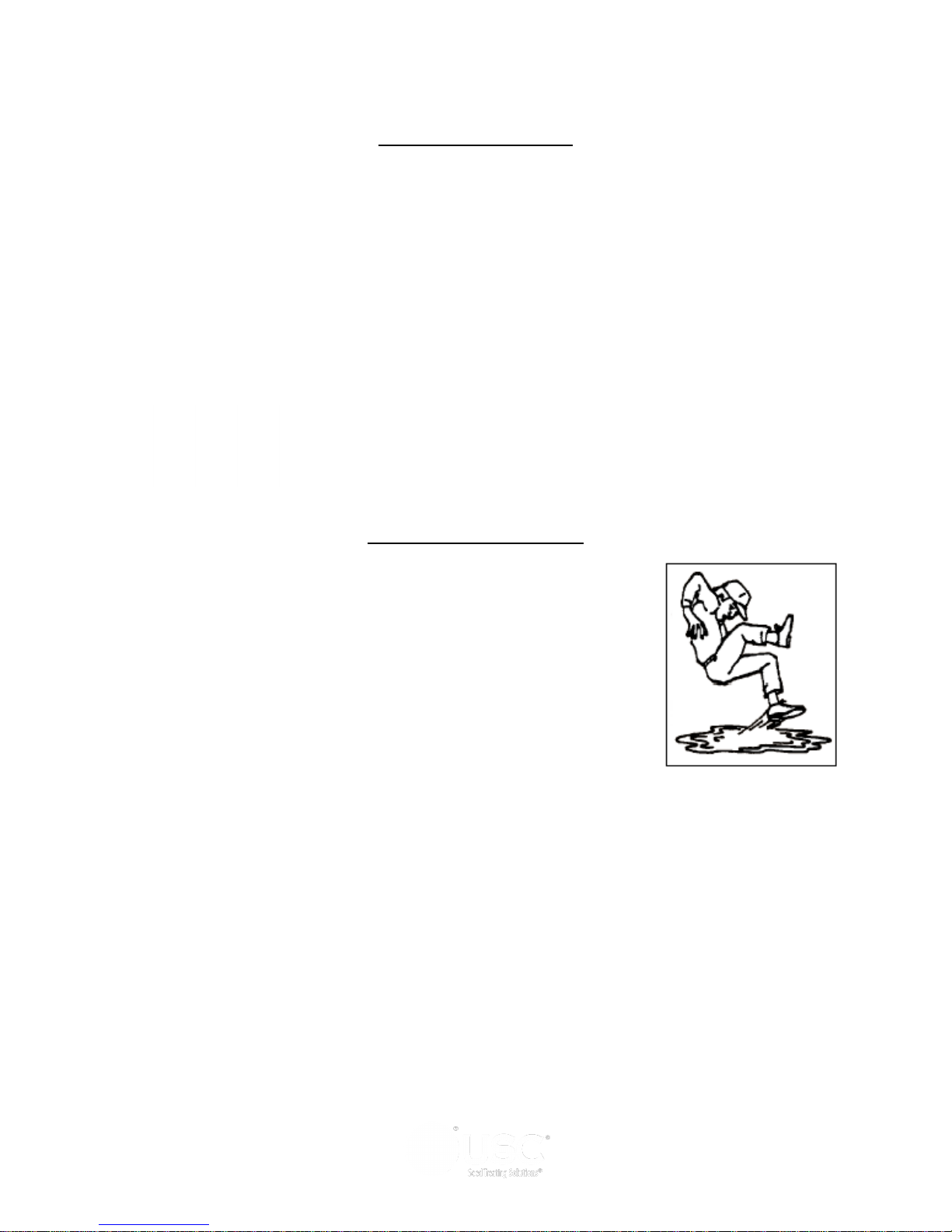
Before placement of the pump stand, be sure that ground is
reasonably level. The pump stand may topple or work improperly
if the ground is too uneven, damaging the equipment and/or
causing personal injury.
MAINTENANCE SAFETY
1. Review the Operator’s Manual and all safety items before
working with, maintaining or operating the LPX Automated
Treater .
2. Place all controls in neutral or off, stop motors, disable power
source, and wait for all moving parts to stop before servicing,
adjusting, repairing or unplugging.
3. Follow good shop practices:
Keep service area clean and dry.
Be sure electrical outlets and tools are properly grounded.
Use adequate light for the job at hand.
4. Keep hands, feet, hair and clothing away from all moving and/or rotating parts.
5. Clear the area of bystanders, especially children, when carrying out any
maintenance and repairs or making any adjustments.
6. Before resuming work, install and secure all guards when maintenance work is
completed.
7. Keep safety signs clean. Replace any sign that is damaged or not clearly visible.
Page 10
Page 11

LPX AUTOMATED SEED TREATER
SAFETY SIGNS
1. Keep safety signs clean and legible at all times.
2. Replace safety signs that are missing or have become illegible.
3. Replaced parts that displayed a safety sign should also display the current sign.
4. Safety signs are available from your Authorized Dealer.
How to Install Safety Signs:
Be sure that the installation area is clean and dry.
Be sure temperature is above 50
Decide on the exact position before you remove the backing paper.
Remove the smallest portion of the split backing paper.
Align the sign over the specified area and carefully press the small portion with
o
F (10oC).
the exposed sticky backing in place.
Slowly peel back the remaining paper and carefully smooth the remaining
portion of the sign in place.
Small air pockets can be pierced with a pin and smoothed out using the piece of
sign backing paper.
Located on the USC equipment you will find safety labels.
Always be sure to read and follow all directions on the labels.
Guards provided with USC LPX Automated Treater are to
remain in place during operation.
Part # 09-02-0001 Part # 09-02-0002
Page 11
Page 12

Section
Section
BB
LPX AUTOMATED SEED TREATER
Installation
Installation
HIGH VOLTAGE ~ Always disconnect the power source
before working on or near the control panel or lead wires.
HIGH VOLTAGE ~ Use insulated tools when making
adjustments while the controls are under power.
Permanent installation may require additional electrical cords,
chemical tubing, and air lines, since each installation is unique.
Inlet
Front
Rear
Discharge
Page 12
Page 13

LPX AUTOMATED SEED TREATER
TREATER SET - UP
The following steps outline the initial set-up of your USC Seed Treating system:
1. Clear the area of bystanders, especially small children, before moving.
2. Be sure there is enough clearance from overhead obstructions and power lines or
other equipment to move the machine into its working position.
3. Using a forklift, place the seed treater in the desired position on a level surface.
USC highly recommends that the seed treater be set up inside a
building or any covered structure to protect the machine from
weathering.
4. Remove any boxes and cords from the drum of the treater.
5. Install the four provided legs and set up on a level surface, preferably concrete.
When all four legs are mounted in the same pin hole, the seed treater has a slight
slope to allow seed to travel through the machine. The pin holes are approximately
2” apart.
If more slope is desired, the rear legs can be dropped an additional
pin hole.
6. Anchor the seed treater in position to prevent the machine from moving during
operation.
7. Inspect machine thoroughly for screws, bolts, fittings, etc. which may have come
loose during shipping.
8. The pump stand(s) should be placed on level ground close to the seed treater.
9. Attach the chemical tubing
from the pump stand(s) to the
atomizer plumbing on the seed
treater (right). Additional tubing
can be added or removed to
accommodate your set-up.
Page 13
Page 14

LPX AUTOMATED SEED TREATER
TREATER SET - UP
10. Setup the Automated Main Control panel at a place that is convenient to the
operator. This may include attaching the automated main control panel to the
seed treater, to the wall, or to the control panel stand that will require anchoring.
11. Connect the gray cable with light blue ends to one of PJCAN connections on the
bottoms of both the treater and automated control panels. Connect the two light
blue plugs into each of the remaining open PJCAN connections.
12. Connect the red cable to the PJESTOPA on the treater control panel and then to
the PJESTOPB on the automated control panel. This cable must run from an A
connection to a B connection (never A to A or B to B). Connect the two red plugs
into each of the remaining open PJESTOP connections.
13. Connect the cables from Pump Stand(s) to applicable port on the Main Control
Panel.
LPX AUTOMATED MAIN CONTROL PANEL
Page 14
Page 15

LPX AUTOMATED SEED TREATER
TREATER SET - UP
LPX AUTOMATED TREATER CONTROL PANEL
Page 15
Page 16
LPX AUTOMATED SEED TREATER
TREATER SET - UP
14. Connect any conveyors that need to be
controlled through the touch screen control
panel to the bottom of the treater control
panel.
.
15. It is required that this air supply have an
in-line customer supplied air dryer to protect
the air system from contamination. Supply
approximately 100 - 110 pounds of air
pressure from the dryer to the port on the
air actuated 3-way valve located on the
pump stand frame behind the electric
control panel.
Air Supplied Here
16. Connect a dedicated analog phone line to
the modem located in the top right portion
of the automated control panel. This will
allow USC remote access to the seed
treater.
Analog Phone Line Hooked Up Here
Page 16
Page 17
LPX AUTOMATED SEED TREATER
TREATER SET - UP
17. Have a certified electrician provide
power to the seed treating system.
Provide convenient shutdown switches,
comply with local electrical codes and
ensure that the system is properly
grounded and bonded. The USC
system must be connected to the same
electrical requirements as specified in
the main control panel on the power
requirement tag, or the electrical
schematic shipped with the piece of
equipment. This will power the USC
LPX seed treater and any attached
conveyors.
Flexible conduit is
recommended for
main power supply.
18. A service port located on the side of the
main control panel will allow the operator
to connect a printer and an Ethernet
connection to the unit. The USB
connection will allow the user to print
reports directly from the reports screen.
USB
Connection
Ethernet
Connection
19. Attach the communication cable from the pump stand control panel to the bottom
of the automated control panel (for an automated pump stand) or to the auxiliary
connection plug on the bottom of the treater control panel (for a manual pump
stand).
20. Provide 110V single phase power to both the main control panel and the pump
stand(s).
Page 17
Page 18

Section
Section
CC
12” Extension Ring
Seed Wheel
Adjustable
Seed Flow
Gate
LPX AUTOMATED SEED TREATER
Mechanical Operation
Mechanical Operation
LPX TREATER OVERVIEW
Rotating
Drum
Quick
Release
Atomizer
Chamber
Handle
Plumbing
To Atomizer
Atomizer Motor
Drum Motor
Treater
Control
Panel
Discharge
Chute
Main
Control
Panel
Adjustable
Legs
Page 18
Page 19

LPX AUTOMATED SEED TREATER
SEED WHEEL
The hopper is equipped with three proximity switches. The top switch controls the inlet
conveyor and the lower switches, located in the seed wheel, control the pump(s).
Refer to H-O-A Screen in section D. See the Proximity Switch Adjustment Guide in
Section F for more in-depth information on these switches.
The Seed Wheel is designed to simplify and increase seed flow calibration accuracy.
A rotating wheel is driven by a variable speed motor, which is set prior to treating the
seed. This is mounted above the atomizer. The wheel consists of 8 identical pockets
approximately 4 inches deep. As it rotates, the wheel captures a certain amount of
seed in each pocket. After the seed is caught, the wheel continues rotation and
dispenses the seed into the atomizer chamber. With the constant turn of the wheel,
there is a consistent amount of seed always sent through the atomizer.
A cup is used to represent a certain percentage of one of the wheels pockets. To
calibrate the seed flow, take a sample of the seed to be treated using the cup and
weigh it (see page 47). By entering the cup weight of the seed sample the system
will automatically adjust the RPM of the Seed Wheel according to the entered target
weight.
The purpose of the seed wheel is to simplify calibration and make seed flow calibration
more accurate. The seed wheel saves time when switching to different seed sizes and
seed types.
Openings to Wheel
Variable
Speed
Motor
Brush
Seed Wheel
Pocket
Opening to
Proximity
Atomizer
Switch
Page 19
Page 20

LPX AUTOMATED SEED TREATER
ATOMIZER CHAMBER
The atomizer chamber consists of a patented design which disperses treatment evenly
to each seed. A motor drives the atomizer head at approximately 1725 RPM’s. As
treatment is being pumped into the atomizer chamber, it drops into the atomizer head.
The centrifugal force of the spinning head forces the treatment to be sprayed out
through a screen covering in all 360 degrees. Meanwhile, seed flows down out of the
seed wheel and down on top of the distribution cone which disperses the seed down
around the atomizer head. The atomizer can be easily accessed for cleaning and
maintenance by pulling down on the quick release handle and sliding the atomizer
away from the treater body. (see page 69)
12” hopper extension
Inlet conveyor
Proximity
Switch
Adjustable
Seed Gate
Lever
Page 20
Quick Release
Atomizer Chamber
Handle
Atomizing
Chamber
Page 21

LPX AUTOMATED SEED TREATER
ROTATING DRUM
The rotating drum comes in options of 6, 8, and 10 feet and accepts treated seed
through the opening on the hopper end. As seed passes through the length of the
drum it is tumbled, producing accurate and uniform seed coating. The seed then exits
the seed treater out the discharge end of the machine.
Never allow exposure of persons or clothing to the drive shaft, idler
wheels, or the drum during operation. Always have the safety
shields in place during operation.
The time it takes for seed to move through the drum both during and at the end of the
run can be changed by lowering or raising the pins on the legs of the discharge end of
the treater. When the pins are in the same hole on all of the treater legs, the treater
has a natural downward tilt towards the discharge end of the treater. Lowering the pins
on the discharge end’s legs will give the treater more tilt during operation which will
allow seed to travel through the drum at a faster rate. Vice verse, raising those pins
will cause seed to stay in the drum longer.
It is not recommended to lower the discharge end’s pins more than
one hole setting different from the inlet end’s pins. If this is done, a
loss in seed coverage and chemical coating may occur.
On the 6 and 8 foot drum options the LPX automated treater will also come standard
with telescoping fork lift pockets. These pockets can be slid out from underneath the
treater to allow a fork lift to pick up the treater from it’s discharge end.
Adjustable
Leg
Telescoping
Fork Pockets
Pin
Page 21
Page 22

LPX AUTOMATED SEED TREATER
PUMP STAND OVERVIEW
Mix Tank
Motor
Dry Lock
Connectors
Mix Tank
Lid
Flow Meter
3 Way Air
Actuated
Valve
Seed Treatment
Return Valve
Mix Tank Motor
On / Off
Switch
Control
Panel
Scale Head
Mix Tank
Mix Tank
Scale
Scale Shipping
Bracket
Page 22
Drain
Valve
Calibration
Tube Holders
Peristaltic
Pump
Heads
Filter
Seed Treatment
Source Valve
Page 23

LPX AUTOMATED SEED TREATER
MIX TANK
The LPX Treater Pump Stand is equipped with a fully modular, touch screen to control
the pump stand. This pump stand will include a 30 or 60 gallon chemical mix tank that
is either of stainless steel or poly construction. This chemical mix tank will have
electric drive agitation that is turned on or off at the pump stand with a manual switch.
The agitator should be running at all times when treatment is present in the mix tank to
keep the chemical mixed and in a suspended state. The tank is equipped with a
shut-off, drain plug, and drain valve located on the bottom. The top of the tank also
includes 3 extra ports which the operator can use to direct fill into the tank (see below).
CALIBRATION TUBE
The LPX Treater Pump Stand is equipped with a
calibration tube which is used to check the liquid flow
rate. The calibration tube measures in ounces, on a
0-340 scale and millimeters on a 0-10000 scale. Manual
valves direct liquid from different areas to keep all liquid
contained. This creates a closed chemical system so
that the operator can manually check the calibration of
the chemical flow rate without handling any of the
chemical.
Page 23
Page 24

LPX AUTOMATED SEED TREATER
PERISTALTIC PUMP HEADS AND MOTOR
The LPX Treater Pump Stand utilizes a variable speed pump motor and special
norprene pump tubing for liquid metering. The pump comes equipped with either
1, 2 or 3 peristaltic pump heads. Liquid will only come into contact with the inside
diameter of the pump tubing and not the pump. This allows for easy cleanup and
less maintenance of the pump.
To open the pump head, lift the lever upward. Place the pump tubing inside the pump
head so it fits inside the notches and above the rollers. Lower the lever back down to
close the pump head, clamping the hose inside the head. Wear or fatiguing of the
tubing within the pump head due to compression is normal. When tubing becomes
worn or chemical rates begin to slow down, open the pump head and move the tubing
to a different position. If the entire piece of tubing becomes worn, simply replace with a
new section. When not using the pump stand for several days or when storing, open
the pump head and remove the tubing to prevent any extra compression.
Pump Head Open Pump Head Closed
If a very low rate is needed, a section of tubing can be removed to force the pump
motor to run at a higher speed. This allows for a more consistent flow rate. When
removing the tubing, uncouple it from the manifold (below, right). If the tubing is
unclamped from the pump head but left coupled in the manifold (below, left), the
pump will suck air and cause flow rates to be very inconsistent.
Page 24
Page 25

LPX AUTOMATED SEED TREATER
FLOW METERS
Each LPX Treater Pump Stand comes with either a volumetric or mass flow meter.
A flow meter is used to perform real-time chemical flow adjustments and monitoring
without the operator having to handle the chemical. The flow meter reading will be
displayed on the HMI touch screen and can be set to read in oz/min or ml/min.
Mass Flow Meter Volumetric Flow Meter
PUMP STAND VALVES
SEED TREATMENT SOURCE VALVE:
This valve controls where the pump is
drawing liquid from. It allows liquid to be pulled from either the bottom of the mix tank
or the calibration tube.
Drawing chemical from the bottom of
the Mix Tank
Drawing chemical from the bottom of
the Calibration Tube
Page 25
Page 26
LPX AUTOMATED SEED TREATER
PUMP STAND VALVES
SEED TREATMENT RETURN VALVE:
This valve directs the liquid coming from the
recirculation side of the Air Actuated 3-Way Valve to either fill the Calibration Tube
or return to the Mix Tank.
Return
Valve
Supply Air
Here
AIR ACTUATED 3-WAY VALVE:
will automatically actuate during normal operation. An internal spring holds the valve
in the recirculation position so that when the valve is not actuated, the chemical will be
directed to flow back to the Mix Tank. When the valve is actuated, the supplied air
pressure will override the spring and move the valve to the PROCESS position.
Chemical flow will then be directed towards the treater’s atomizer chamber.
Page 26
This valve is controlled from the touch screen and
Page 27

LPX AUTOMATED SEED TREATER
PUMP STAND VALVES
Proper calibration of the liquid system is critical to achieve a proper granular/chemical
mixture. Use the calibration procedure on page 50 and 51 to determine liquid flow
rate.
Emptying the remaining liquid can be done by using the reverse function on the control
panel. This will pump liquid back into the mix tank. Then drain the remaining liquid
into a suitable container. Clean water should be pumped through the calibration tube
and mix tank when finished.
Always dispose of chemical or diluted chemical according to your
local, state, and federal regulations.
Only you, the operator, can determine the length of time required to
completely rinse all chemical residue from the tank and plumbing
system.
Page 27
Page 28

LPX AUTOMATED SEED TREATER
Section
Section
Electrical Operation
DD
This section provides a general overview and description of the operator controls for
the LPX Automated Seed Treater.
General Panel Descriptions
Electrical Operation
HIGH VOLTAGE ~ Always disconnect the power source
before working on or near the control panel or lead wires.
HIGH VOLTAGE ~ Use insulated tools when making
adjustments while the controls are under power.
AUTHORIZED PERSONNEL only shall work on the control
panel. Never allow anyone who has not read and familiarized
themselves with the owner’s manual to open or work on the
control panel.e switch is turned on,
This system consists of three plug connected panels, one hard wired panel and two
more optional plug connected panels:
The LPX Treater Main Panel is an enclosure that is attached to the side of the
treater and contains the electrical components required to actuate the seed treater.
This includes the VFDs for the seed wheel and atomizer. Power for the treater is
supplied here. Power to this panel is hard wired.
The LPX Automated Main Control Panel is a plug connected enclosure that
contains the PLC (Programmable Logic Controller) as well as the HMI (Human
Machine Interface) touch screen. The operator is able to control the entire system
through the HMI. Power to this panel is supplied from a standard 110V plug.
The LPX Automated Pump Stand Panel is a plug connected enclosure that is
located on each pump stand frame. This panel connects the pump stand electrical
components to the Automated Main Control Panel. Each pump stand has two
standard 110V plugs. One for the manual ON/OFF switch controlling the mix tank
motor and one for the pump stand control panel.
Page 28
Page 29

LPX AUTOMATED SEED TREATER
MAIN CONTROL PANEL
The following pages explain the function of the touch screen controls.
USC STARTUP SCREEN
While the system is booting up, the treater touch screen will display a timer. Once the
timer reaches zero, this screen is the first screen the operator will see after the system
receives power. Touch this screen to allow the operator to advance to the Main
screen.
The E-Stop Reset push button must be pressed after every power
cycle and every time the E-Stop is activated or the system will not
operate.
Page 29
Page 30
LPX AUTOMATED SEED TREATER
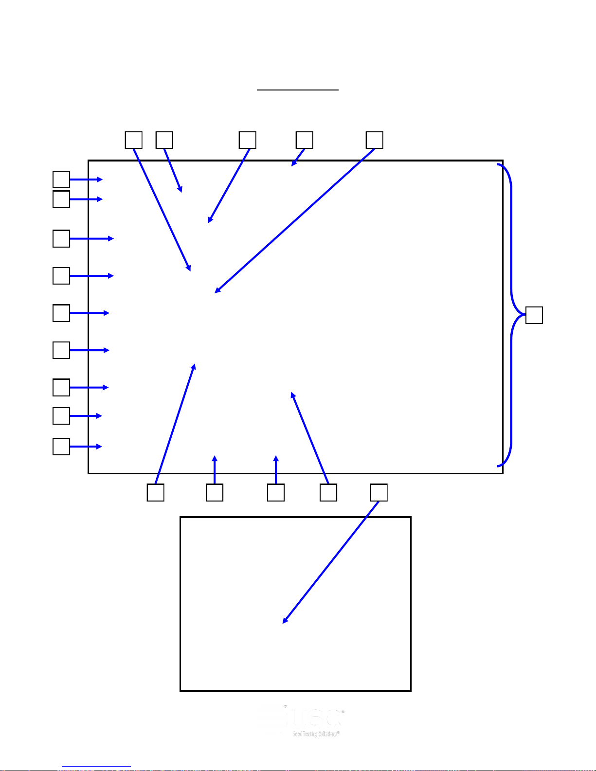
MAIN SCREEN
This screen informs the operator of the status of all system motors and electrical
devices and allows for control/adjustment of system operations.
6
7
8
9
10
11
12
13
1 2 4 3
5
15
14
Page 30
16 17 18
19
20
Page 31

LPX AUTOMATED SEED TREATER
Main Screen Button Descriptions
1. SEED FLOW RATE:
2. SEED TYPE INDICATOR:
“Product Selection” screen.
3. TOTALIZED WEIGHT DISPLAY:
through the seed wheel.
Displays the seed flow rate in pounds per minute.
Displays the type of seed has been selected in the
Displays the total pounds of seed as it passes
4. CURRENT DATE AND TIME DISPLAY.
5. SEED WHEEL MOTOR STATUS INDICATOR:
wheel is ON or OFF.
6. HOPPER FULL:
supply hopper above the seed wheel is detecting seed. When the indicator is active
any equipment plugged into the Inlet Conveyor plug will be turned off.
7. HOPPER EMPTY:
seed wheel are not detecting seed.
Informs the operator when the proximity switch located in the
Informs the operator when the proximity switches located in the
8. INLET CONVEYOR MOTOR STATUS INDICATOR:
inlet conveyor is ON or OFF”
9. OUTLET CONVEYOR MOTOR STATUS INDICATOR:
outlet conveyor is ON or OFF.
Informs the operator if the seed
Informs the operator if the
Informs the operator if the
10. SEEDS / LB:
mode. This indicator will only appear if at least one of the pump stands has been set
to run in the SCU mode.
11. CUP WEIGHT:
allows the operator to input the cup weight for the Seed Wheel.
12. H-O-A”(Hand-Off-Auto):
(page 33).
13. UTILITIES:
14. USC LOGO BUTTON:
site this button allows the operator to toggle back and forth between the main treater
screen and the main bin site screen.
Indicates how many seeds are in a pound when running in SCU
Pressing this button will bring up a numeric keypad (below) which
This button advances the operator to the H-O-A screen
This button advances the operator to the “Utilities” screen (page 37).
When the treater is being used in conjunction with a bin
Page 31
Page 32
LPX AUTOMATED SEED TREATER
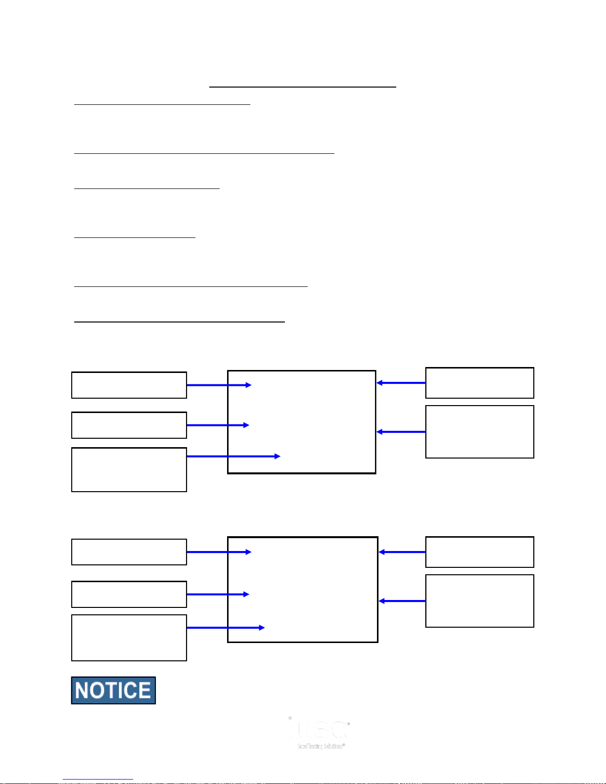
Main Screen Button Descriptions
15. PUMP STATUS MODULES:
This block of information informs the operator of the
pump motor status ON or OFF, air actuated 3-way valve status, currently selected
chemical, target flow rate and actual flow rate from flow meter.
16. ATOMIZER MOTOR STATUS INDICATOR:
Informs the operator if the atomizer
motor is ON or OFF.
17. USC LOGO BUTTON
: Allows the operator to toggle to the Start screen. Once
the START button is pushed and the system begins to operate it becomes the PAUSE
button.
18. START BUTTON:
This is used to start the machine after all motors have been
placed into the AUTO position. Once the button is pushed and the system begins to
operate it becomes the SHUTDOWN button.
19. DRUM MOTOR STATUS INDICATOR:
Informs the operator if the drum drive
motor is ON or OFF”.
20. EMERGENCY STOP INDICATOR:
This blinking display is activated when the
system’s E-Stop button is activated.
CUT WEIGHT / OUNCES PER MINUTE
Chemical Name
Pump Motor Status
( ON or OFF )
Target Chemical Rate
per 100 lbs of Seed
Actual Flow Rate of
Pump on a per
minute basis
SEED COUNT UNITS / OUNCES PER CUT WEIGHT
Chemical Name
Target Chemical Rate
per Seed Count Unit
Actual Flow Rate of
Pump on a hundred
weight basis
Informs the operator
if the Pump is in
Re-circulate or
Process
Pump Motor Status
( ON or OFF )
Informs the operator
if the Pump is in
Re-circulate or
Process
Actual flow rate of pump may be defined as either oz/min or oz/cwt
regardless of the target rate setting (oz/cwt or oz/scu)
Page 32
Page 33
LPX AUTOMATED SEED TREATER
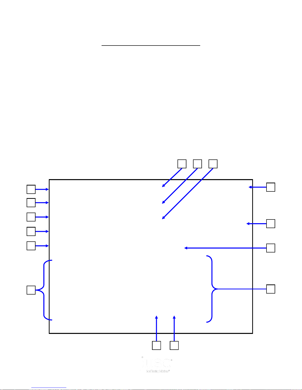
H-O-A (HAND-OFF-AUTO) SCREEN
Hand-Off-Auto controls are provided for most of the automated devices in the system,
and are accessed on this screen.
These H-O-A buttons force the selected component to be energized
(HAND), de-energized (OFF), or automatically energized by the
normal logic sequence (AUTO). The HAND function will cause the
component to operate independent of whatever else the system is
trying to do automatically. These functions should not normally be
used if the automated sequencing is active. Be sure to
understand the impact of energizing or de-energizing a
component with the HAND/OFF settings before using them.
These commands are not a substitute for Lockout/Tagout
procedures when working on or near this machine. Use proper
lockout/tagout procedures to disable the equipment before
servicing it.
2 4 6
1
3
5
7
8
9
10
11
12
13
14
15
Page 33
Page 34
LPX AUTOMATED SEED TREATER
H-O-A Button Descriptions
1. DRUM CONTROL MODULE:
This module controls the function of the drum. The
HAND button will place the drum in the manual mode of operation. The OFF button
will turn the associated device in the OFF mode of operation. The AUTO button will
place the device in the automatic mode of operation. The motor will not operate in this
function unless all other needed devices are in the AUTO mode and the START button
is pressed on the main screen.
2. DRUM PERCENT SPEED:
When this button is pressed, a numeric touch pad
(bottom) will appear to allow the operator to manually adjust the speed of the drum.
3. ATOMIZER CONTROL MODULE:
This module controls the function of the
atomizer. The HAND button will place the atomizer in the manual mode of operation.
The OFF button will turn the associated device in the OFF mode of operation. The
AUTO button will place the device in the automatic mode of operation. The motor will
not operate in this function unless all other needed devices are in the AUTO mode and
either the PRIME TO ATOMIZER or the START button is pressed on the main screen.
4. ATOMIZER PERCENT SPEED:
When this button is pressed, a numeric touch pad
(bottom) will appear to allow the operator to manually adjust the speed of the atomizer.
5. SEED WHEEL CONTROL MODULE:
This
module controls the function of the seed wheel.
The HAND button will place the seed wheel in
the manual mode of operation. This module
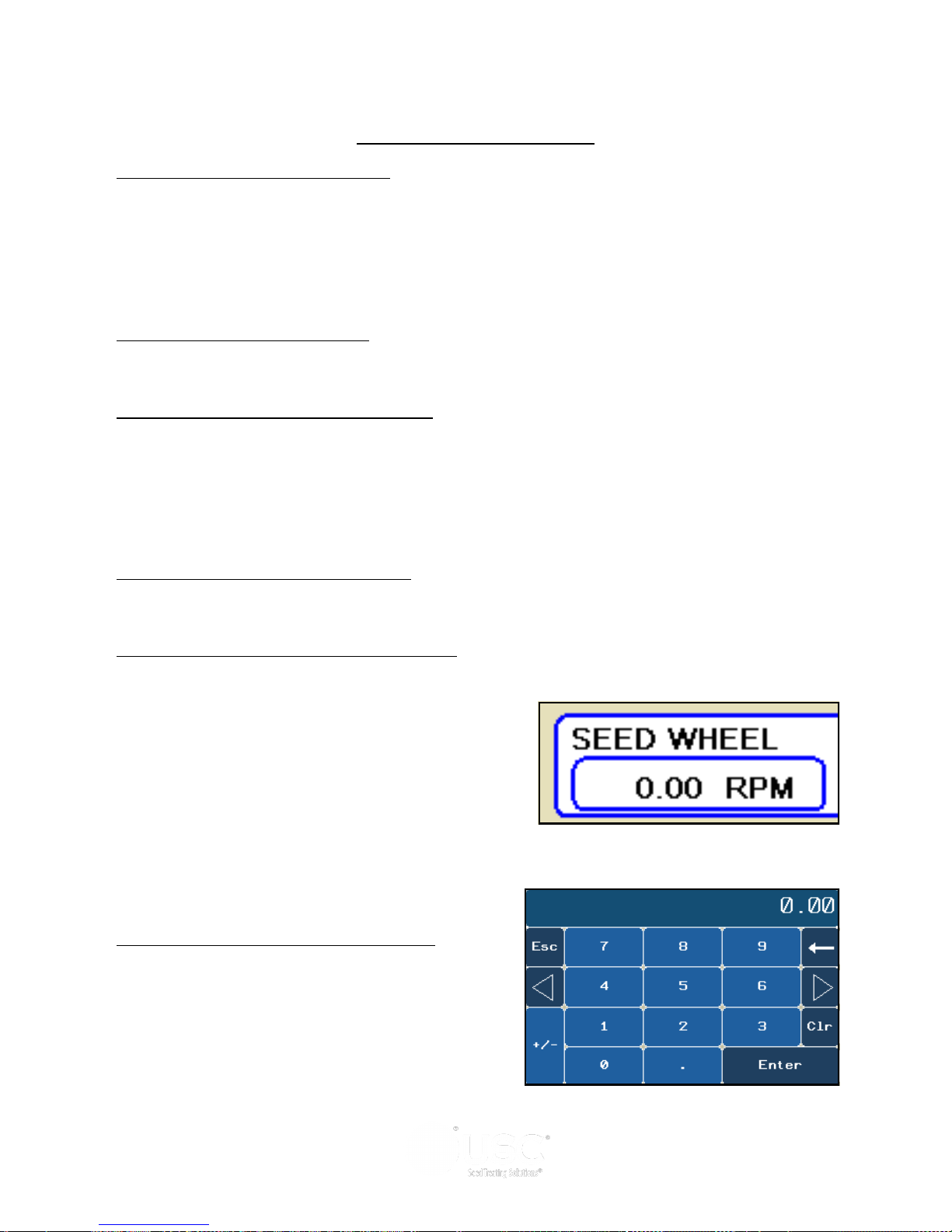
shows the current RPM of the seed wheel
(right). The OFF button will turn the associated
device in the OFF mode of operation. The
AUTO button will place the device in the
automatic mode of operation. The motor will
not operate in this function unless all other
needed devices are in the AUTO mode and the
START button is pressed on the main screen.
6. SEED WHEEL PERCENT SPEED:
When
this button is pressed, a numeric touch pad
(right) will appear to allow the operator to
manually adjust the speed of the seed wheel.
When running in the AUTO mode the program
will override this setting.
Page 34
Page 35

LPX AUTOMATED SEED TREATER
H-O-A Button Descriptions
7. INLET CONVEYOR CONTROL MODULE:
This module controls the function of
the inlet conveyor. The HAND button will place the inlet conveyor in the manual mode
of operation. The OFF button will turn the associated device in the OFF mode of
operation. The AUTO button will place the device in the automatic mode of operation.
The motor will not operate in this function unless all other needed devices are in the
AUTO mode and the START button is pressed on the main screen. When the
proximity switch located in the supply hopper above the seed wheel is detecting seed
and the indicator is active, any equipment plugged into the Inlet Conveyor plug will be
turned off.
8. OUTLET CONVEYOR CONTROL MODULE:
This module controls the function of
the outlet conveyor. The HAND button will place the outlet conveyor in the manual
mode of operation. The OFF button will turn the associated device in the OFF mode
of operation. The AUTO button will place the device in the automatic mode of
operation. The motor will not operate in this function unless all other needed devices
are in the AUTO mode and the START button is pressed on the main screen.
9. PUMP CONTROL MODULES:
These modules control the function of the
Pump Stands. The HAND button will place the desired pump in the manual mode of
operation. The OFF button will turn the associated device in the OFF mode of
operation. The AUTO button will place the device in the automatic mode of operation.
The pump will not operate in this function until the START button is pressed on the
main screen. This module also monitors the proximity sensor in the Seed Wheel.
When the proximity switch is detecting seed and the indicator is active, the 3 - way
valve will switch to PROCESS. When no seed is detected it will switch to RECIRC.
10. SCREEN EXIT BUTTON:
This button is used to exit back to the previous screen.
Its functionality is the same throughout the HMI display.
11. AUXILIARY CONTROL:
This module allows the operator to control any unit
which is plugged into the auxiliary port located on the bottom of the automated treater
control panel. The HAND button will allow the user to operate the unit in the manual
mode of operation. The OFF button will disconnect control to the auxiliary port. The
AUTO button will place the unit in the automatic mode of operation. Any unit plugged
into the auxiliary port will not operate in this function until the START button is pressed
on the main screen. It will also turn off using the same logic as the pump stands. See
picture (page 36, top).
Page 35
Page 36
LPX AUTOMATED SEED TREATER
H-O-A Button Descriptions
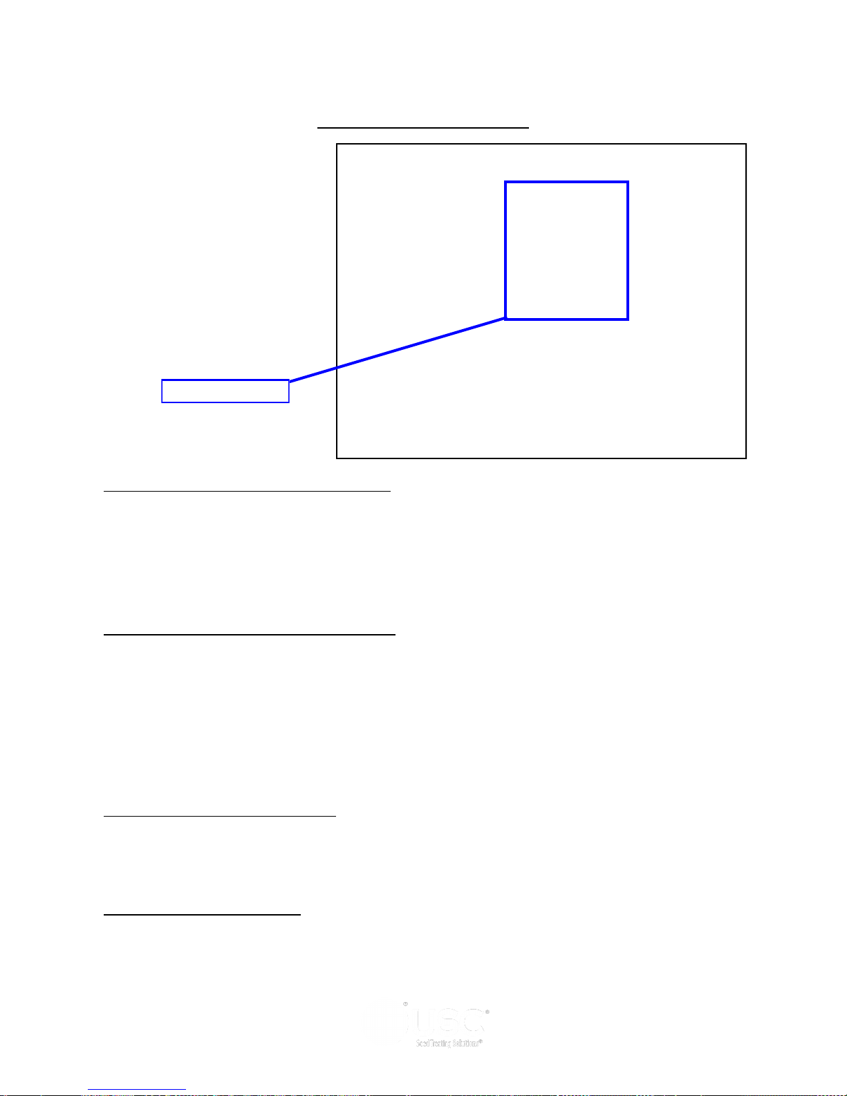
Auxiliary Ports
12. PRIME TO ATOMIZER BUTTON:
Used before a controlled startup to preload
chemical in the tubing leading to the atomizer. To operate this button, place the
atomizer and any pump that will be used in the AUTO mode. Next press and hold the
PRIME TO ATOMIZER button. The atomizer and pumps will turn on and the liquid will
be directed to the atomizer. The atomizer and pumps will run as long as the button is
being pressed. When the button is released the atomizer and pumps will shut-off.
13. AIR VALVE CONTROL MODULE:
This module controls where liquid is diverted
for each pump. When a desired pump is placed in the HAND mode, the RECIRC
button will appear next to that pump control module. In this mode, liquid is pumped out
of its desired tank, through the air actuated 3-way valve manifold and back into the mix
tank. When the RECIRC. button is pressed, the icon will change to PROCESS. In this
mode, liquid is diverted from the air actuated 3-way valve, to the atomizer. When the
OFF button is pressed the pump will go back to RECIRC. When the pump is placed in
the AUTO mode the Air Valve Control cannot be accessed.
14. PUMP PERCENT SPEED:
When this button is pressed, a numeric touch pad
will appear to allow the operator to manually adjust the speed of the pump(s). When
running in the AUTO mode the program will override this setting.
15. REVERSE BUTTON:
Allows the operator to reverse the pump direction and
pump the product back into the mix tank. When the pump is in Hand or Auto mode,
this button will become a display for the actual pump flow rate. When running in the
AUTO mode the program will override this setting.
Page 36
Page 37
LPX AUTOMATED SEED TREATER
UTILITIES SCREEN
This screen allows the operator to set various system parameters and gives access to
the Reports, Product Selection, Security, Alarms, Customer Information and General
Information screens.
1
2
3
4
13
5
8 7 6 9 12 10 11
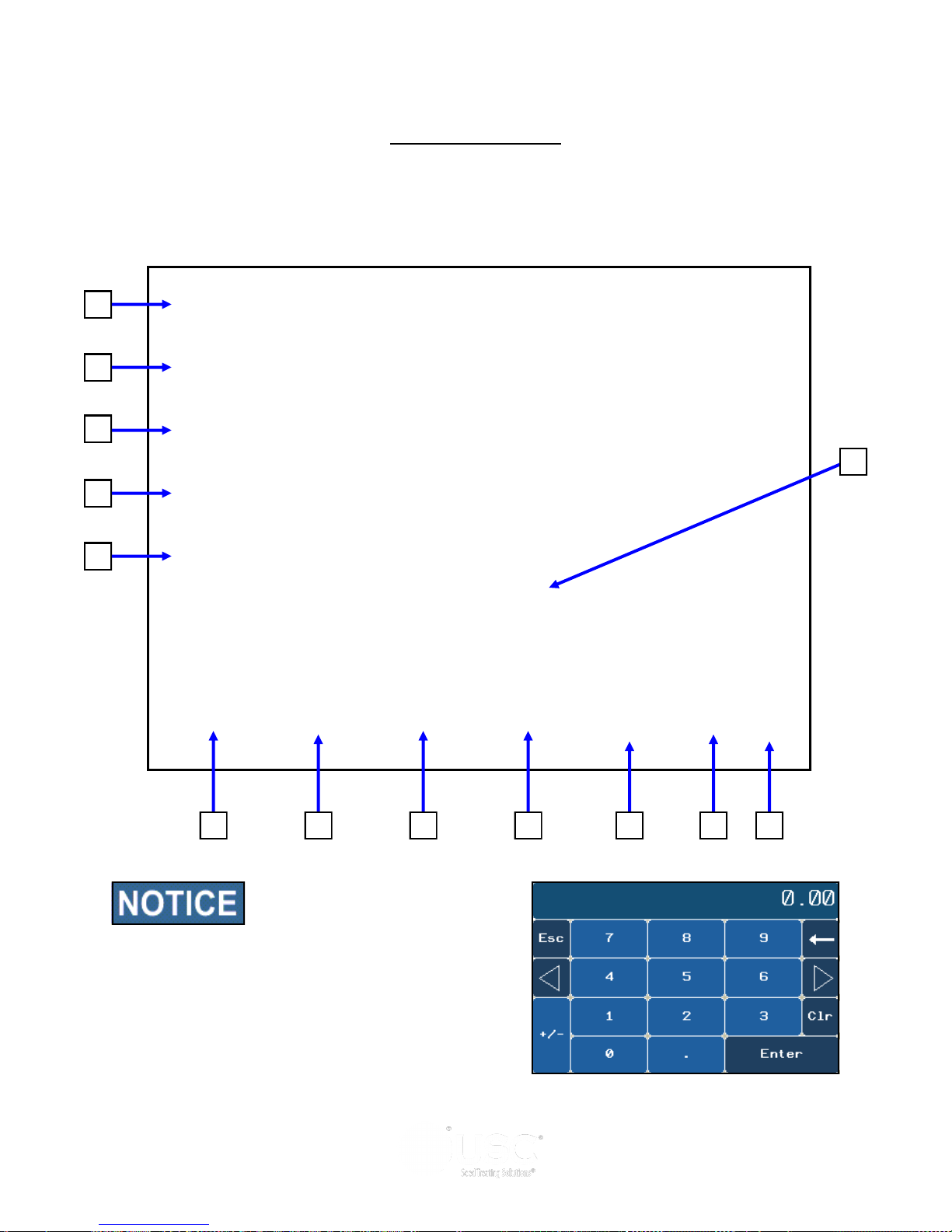
When buttons 1-5 are pressed,
a numeric touch pad (right) will
appear allowing the operator to
enter in a number for that
particular parameter.
Page 37
Page 38

LPX AUTOMATED SEED TREATER
Utilities Screen Button Descriptions
1. TARGET TREATING RATE:
estimated treating rate in pounds per minute. This number is used by the system to
control the rate of the seed wheel and pumps.
2. PUMP PRE-START TIME:
start time of the pumps based on the proximity sensor in the seed wheel detecting
seed and the timing of the seed wheel turning on. This number will allow the air
actuated 3-way valve to actuate and begin sending liquid to the seed treater a
pre-defined number of seconds before the seed wheel will turn on. This will help
prevent any untreated seed at the beginning of a run.
3. PUMP DELAY SHUT-OFF TIME:
adjust the delay shut-off time of the pumps after the proximity switches located in the
seed wheel do not detect anymore seed.
4. INLET CONVEYOR DELAY RESTART TIME:
operator to adjust the restart time of the inlet conveyor after the proximity switch
located at the top of the inlet hopper above the seed wheel no longer detects seed.
5. TREATER SHUTDOWN TIME:
the delay shutdown time of the seed treater after the SHUTDOWN button has been
pressed after a run. This time will allow the seed treater and any conveyors to
completely clean out.
Pressing this button allows the operator to adjust the
Pressing this button allows the operator to adjust the
Pressing this button allows the operator to
Pressing this button allows the
Pressing this button allows the operator to adjust
6. REPORTS:
7. PRODUCT SELECTION:
Selection screen (page 49).
8. SECURITY:
9. ALARMS:
10. CUSTOMER INFO:
Information screen (page 45).
11. INFORMATION:
where the operator can find vital information on storage and troubleshooting.
12. ABOUT USC:
operator what software release is installed.
13. AUTO RATE ADJUST TO BIN SITE:
Tri - Flo™ and USC Bin Site Automation). When this box is checked, Target Treating
Rate will automatically be adjusted to 2% slower than the bin site.
This button advances the operator to the Reports screen (page 55).
This button advances the operator to the Product
This button advances the operator to the Security screen (page 39).
This button advances the operator to the Alarms screen (page 64).
This button advances the operator to the Customer
This button advances the operator to the information screen
Pressing this button brings up a popup screen showing the
(Only present when treater is used with a
Page 38
Page 39
1
2
3
LPX AUTOMATED SEED TREATER
SECURITY SCREEN
4
Security Screen Button Descriptions
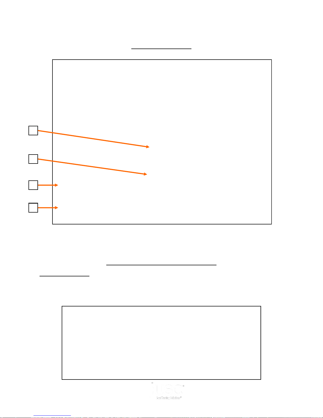
1. PASSWORD :
The operator uses this input to obtain access to ALL options on this
screen. When this button is pressed a keypad (bottom) will appear on the screen.
The password is USC and should only be made accessible to personnel qualified to
operate the seed treater. The User Name will stay OPERATOR.
Page 39
Page 40

LPX AUTOMATED SEED TREATER
Security Screen Button Descriptions
2. LOGOUT BUTTON:
Pressing this button will log the operator out of the Security
screen. However, the operator will be automatically logged out after five minutes of
inactivity or the operator has moved to the Main screen.
3. SEED WHEEL CALIBRATION SCREEN:
Pressing this button will advance the
operator to the Seed Wheel Calibration screen (below).
4. TOOLS & OPTIONS:
Tools & Options screen (page 41).
Page 40
Pressing this button will advance the operator to the
Page 41
1
2
3
4
5
LPX AUTOMATED SEED TREATER
TOOLS & OPTIONS SCREEN
6
7
1. PUMP STAND SETTINGS:
This button advances the operator to the Pump Stand
Settings screen where the Flow Rate Entry Type can be set for cut weight or seed
count units and the Flow Rate Display can be set for ounces per minute or ounces
per cut weight for each individual Pump Stand.
8
9
Page 41
Page 42
LPX AUTOMATED SEED TREATER
Tools & Options Button Descriptions
2. EDIT CHEMICAL NAMES:
better fit their needs. Pressing this button will advance the operator to the Edit
Chemical Name screen (top) . Selecting one of the Chemical buttons brings up an
alpha numeric screen to enter the desired name. Pressing the CALC button for that
chemical name brings up the Chemical Factor Calculator window (bottom left). From
this screen the operator can determine the chemical multiplier by entering the
Calibration Tube amount and the Totalizer amount. Press save and the multiplier is
automatically calculated and entered. Another window will prompt the operator to
verify this information on the main screen Pump Stand module (bottom right).
Chemical Name
Press this button
to bring up the
Chemical Factor
Calculator
Allows the operator to change the chemical names to
Page 42
Page 43

LPX AUTOMATED SEED TREATER
Tools & Options Button Descriptions
2. EDIT CHEMICAL NAMES (continued):
Selecting the light bulb help button in the
upper left corner brings up the Flow Meter Calibration instructions.
3. DATE & TIME:
Allows the operator to set the date and time.
Page 43
Page 44

LPX AUTOMATED SEED TREATER
Tools & Options Button Descriptions
4. STANDARD/METRIC UNITS:
Allows the operator to switch between Standard
or Metric units of measurement. When this button is pressed a window will appear
which will allow the operator to the select the desired units of measurement.
5. PRINT SETUP:
Allows the operator to set up their personal company information
which will be printed at the top of each report. Pressing the button will advance the
operator to the screen below. The company information can be entered by selecting
the blank space under each heading. The operator may also check the Auto Print box
to print a report for a customer every time a report is generated as well as how many
copies the customer requires.
Page 44
Page 45

LPX AUTOMATED SEED TREATER
Tools & Options Button Descriptions
6. EDIT PRODUCT NAMES:
Pressing the button will advance the operator to the
Edit Product screen (top). Select one of the product name buttons and an alpha
numeric popup will appear allowing the operator to change the name. Also, you
may enter a value if you are using the Seed Count Unit of measurement.
7. CUSTOMER INFO:
Pressing the button will advance the operator to the Customer
Info screen (bottom left). If you are looking for a specific customer you may press the
< ENTER SEARCH NAME> button and key in the name or use the arrows to scroll
through the listing. Selecting the CREATE NEW ENTRY button (bottom, right) allows
the operator to create a new customer listing.
Page 45
Page 46

LPX AUTOMATED SEED TREATER
Tools & Options Button Descriptions
8. CLEAR ALL REPORTS:
Pressing this button will open a window which will ask the
operator if they want to clear all the saved reports. If YES is pressed then the reports
will be permanently erased. The operator MUST NOT leave the screen until all files
have been cleared out.
9. SEND REPORTS TO USB:
Pressing this button will open a window which will ask
the operator if they want to send reports to a USB device. Insert a compact flash
device into the USB port on the left side of the control panel. The device must be in
the FAT32 format. Press YES and the reports will be downloaded.
Page 46
Page 47
LPX AUTOMATED SEED TREATER
Section
Section
Calibration
Calibration
EE
SEED FLOW CALIBRATION
The following is a list of steps to use when calibrating the seed wheel. A seed
calibration cup, funnel, stand, and scale are used to calibrate the seed wheel.
1. Set the empty seed calibration cup on the scale and zero out
the weight of the cup.
2. Place the funnel and stand in the seed to be treated or a
separate container (figure 1). This will help to avoid any
unnecessary clean-up while filling and leveling the top of the
seed calibration cup.
3. Place your hand under the bottom of the funnel and fill the
funnel up with seed.
Seed Calibration Cup
4. Place the calibration cup under the funnel stand and remove your hand from the
bottom of the funnel, and allow the cup to be filled. (figure 1)
5. After the cup has been filled, strike off the top of the calibration cup with a straight
edge. (figure 2)
Do not shake the cup.
6. Weigh the sample of seed. (figure 3)
A typical weight of the sample of seed will be anywhere between 2.8 to
4.0 lbs. Anything over or under this range could be caused by not zeroing
out the weight of the cup, or the scale may be set on the wrong units.
Figure 1
Figure 2 Figure 3
Page 47
Page 48
LPX AUTOMATED SEED TREATER
SEED FLOW CALIBRATION
7. Take the weight of the seed sample and
enter it into the main screen under CUP
WEIGHT.
Enter Seed
Sample
Weight Here
8. Press the UTILITIES button on the main screen to advance to the utilities screen.
Enter in the TARGET TREATING RATE in pounds per minute. Also at this time fill
in all other parameters on this screen. Below is a screen shot of the utilities screen
with typical numbers to use when beginning to treat.
Page 48
Page 49
LPX AUTOMATED SEED TREATER
SEED FLOW CALIBRATION
9. Next, press the PRODUCT SELECTION SCREEN button to advance to the product
selection screen. Select the type of seed you will be treating. A confirmation
window will appear to confirm the selection. Press YES to complete the change
(top). If you wish to use the default setting for that seed press the RESET
DEFAULT button in the lower left corner of the screen and a confirmation window
will appear, press YES to confirm this (bottom). Press the help button in the lower
right corner and a help window will show how the operator can edit the product
names.
Select Product
Confirmation
Default Confirmation
Help Screen
Page 49
Page 50
LPX AUTOMATED SEED TREATER
PUMP CALIBRATION
1. Lock down the pump tubing in the pump head. (page 24)
2. Premix enough liquid for the amount of seed you are treating and pour into the
chemical mix tank. It’s always a good practice to mix an extra half gallon of slurry
to help fill all the lines.
3. On the automated mix tank control panel, place the mix tank motor to the ON
position. This will ensure that the chemical mixture within the mix tank is blended
appropriately.
4. From the MAIN screen, select the chemical name box from the desired pump
module and a selection window appears. Choose the type of chemical you will be
applying. Press the TARGET RATE box below the chemical name on the main
screen and you will be taken to the EDIT CHEMICAL NAME screen. Select the
RATE box next to the applicable chemical name and use the keypad to enter the
value. Select the red X twice to return to the main screen to verify the changes.
See edit chemical names on page 42 for more detail.
Enter in
Ounces per
cwt. here
Choose
chemical
name here
Page 50
Page 51
LPX AUTOMATED SEED TREATER
FLOW METER CALIBRATION
Due to the composition of some types of chemicals, additional flow meter calibration
may be required. It is recommended that, like other calibration devices, the flow
meter(s) is checked regularly and calibrated when needed. When calibrating the flow
meter(s), each chemical slurry must be checked and adjusted for.
1. To begin the calibration process, fill the
appropriate mix tank with the slurry that is
going to be used for this calibration.
2. Turn the corresponding pump to the hand
position and adjust the flow rate until it reads
about 20 percent on the pump control module
(top). Let the system run in recirculation mode
for 15 minutes. This will remove any air from
the system.
3. Using a stop watch, place the MIX TANK/
CALIBRATION TUBE valve that is located on
top of the mix tank (middle) to the calibration
tube position and begin timing for one minute.
When one minute is up, place the valve back in
the mix tank position. Note the total ounces of
chemical that is in the calibration tube. Also,
note the reading of the flow meter on the main
screen.
4. From the Edit Chemical Screen (bottom) press
the button for the corresponding chemical and
the Chemical Factor Calculator appears. Enter
the calibration tube ounces into the calibration
tube box and the flow meter reading into the
totalizer box. Press the SAVE button and it will
automatically calculate the multiplier and enter
it for that chemical.
5. Exit to the main screen and re-select the
chemical name to set the new multiplier and
ensure proper calibration on this chemical.
The multiplier will not show up on the screen
but will be used by the system for calibration
purposes.
6. Repeat the process as necessary and for each
different chemical slurry used.
Page 51
Page 52

LPX AUTOMATED SEED TREATER
SEED WHEEL CALIBRATION
1. If the totalized weight from the seed wheel differs from the actual weight of the
seed that was ran through the treater. The seed wheel can be calibrated to
increase accuracy. Press the Utilities button on the Main screen. Next, press the
SECURITY button to advance to the security screen (top). Enter the Password
USC, then press the Seed Wheel Calibration button. This will advance you to the
Seed Wheel Calibration screen (bottom).
2. Enter in the ACTUAL SCALE WEIGHT of the seed that was treated, and the
TOTALIZER WEIGHT from what the seed wheel recorded.
3. Press the APPLY button. The PLC will automatically calibrate the seed wheel and
exit back to the main screen.
Page 52
Page 53
LPX AUTOMATED SEED TREATER
TREATING SEED
1. Under the H-O-A screen, place the DRUM, ATOMIZER, SEED WHEEL, INLET
CONVEYOR, OUTLET CONVEYOR and desired pumps in AUTO.
2. Next, prime the chemical line to the atomizer. Ensure that the valve on each of the
chemical attachment ports on the treater are in the correct position. Then, press
and hold the PRIME TO ATOMIZER button. The atomizer will turn on and liquid
will begin pumping up to the atomizer. When liquid reaches the atomizer release
the PRIME TO ATOMIZER button.
AUTO
Buttons
Prime to
Atomizer
Button
3. Return to the main screen and press the START button. The Customer Information
screen appears. Either select the customer name from the listing or use the
keypad to enter it along with the seed information. Press START to begin the run.
The drum, atomizer, inlet conveyor and outlet conveyor will activate. The pump
will turn on and re-circulate until it reaches the desired flow rate needed to match
the target treating rate that was entered. The inlet conveyor will then begin
dumping seed into the seed wheel.
Page 53
Page 54
LPX AUTOMATED SEED TREATER
TREATING SEED
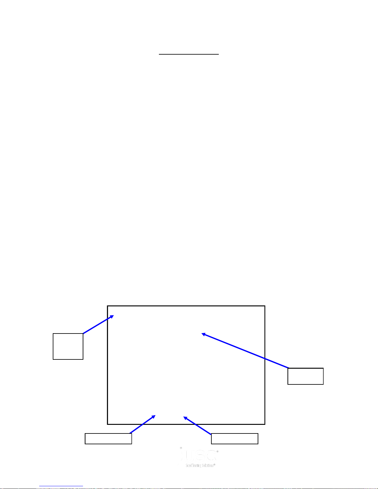
4. When the pump’s flow rate has been reached and seed is covering the proximity
sensors inside of the seed wheel, the air actuated 3-way valve will open and allow
liquid to pump up to the atomizer. A moment later (based on the settings in the
utilities screen), the seed wheel will turn on and the seed treating process will
begin.
5. As the seed is being treated. The main screen will display the pounds per minute,
the total pounds, and the liquid flow rate. If the system needs to be stopped for a
moment because of a problem. The PAUSE button can be pressed to halt the
process. When ready to begin again, the CONTINUE button is pressed.
6. When the seed wheel hopper is full the HOPPER FULL indicator light will come on
and the inlet conveyor will shut off. The flow of seed into the treater will begin
again once seed is no longer present at the top proximity sensor in the hopper and
the Inlet Conveyor Delay Restart time defined on the utilities has expired. This is
done to ensure that seed will not overfill the hopper and flow onto the ground.
7. When all seed passes through the seed wheel, the seed wheel will turn off and the
pump will switch to re-circulate. When more seed is fed into the treater, the treating
process will continue.
8. After all seed has been treated the inlet conveyor and the seed wheel will
shutdown automatically. The 3-way valve on the pump stand will switch to
re-circulate. However, the atomizer, drum and outlet conveyor will still be running.
Press the SHUTDOWN button at the bottom of the screen and the shutdown timer
appears and begins to count down the seconds left before complete shutdown.
The operator decides how much time is adequate for all product to clear the drum
and outlet conveyor. The time is entered on the utilities screen and can be
adjusted whenever necessary.
Hopper
Full
Indicator
Shutdown
Timer
Pause Button
Page 54
Shutdown
Page 55
LPX AUTOMATED SEED TREATER
EDITING & PRINTING REPORTS
The following steps explain how reports are entered after a run has been completed.
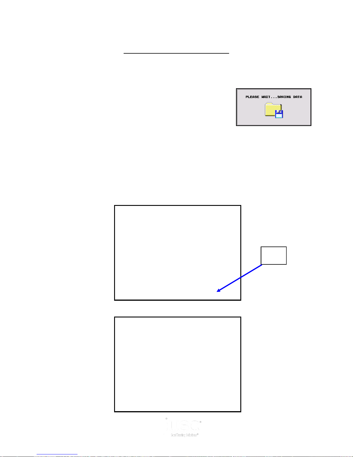
1. After the SHUTDOWN button has been pressed a
dialog box will appear (right), notifying the operator
that the data from the run is being saved.
2. Once the data has been saved, the operator will be brought to a TREATER
REPORTS screen (top). Under the reports screen, the customers information and
seed information can be recorded and saved for later use. Press the EDIT button
and go to the EDIT TREATER REPORTS screen (bottom). From this screen you
can change the customer name, seed variety, and lot number. Pressing the cells
next to each piece of information will bring up a keypad which will allow the
operator to enter in the information. When finished the operator can press the
OK button to save the data.
Edit
Button
Page 55
Page 56
LPX AUTOMATED SEED TREATER
EDITING & PRINTING REPORTS
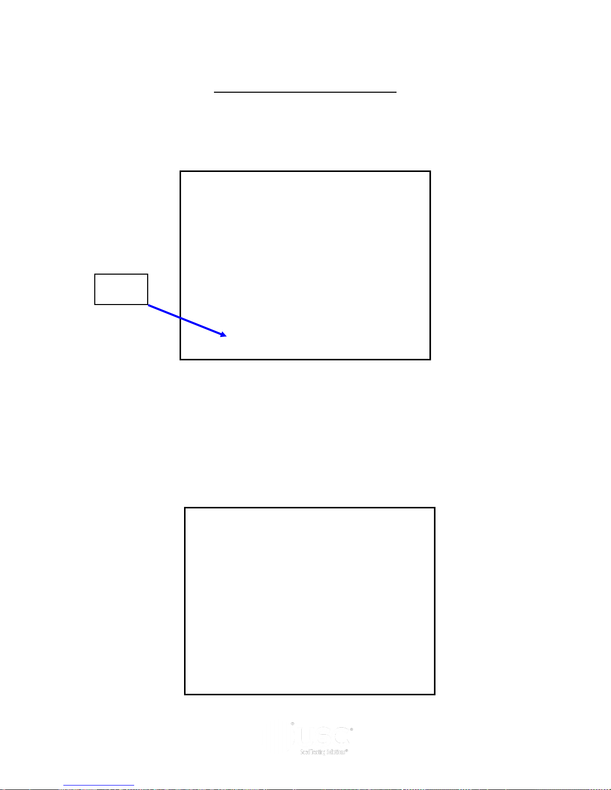
3. Press the PRINT button and a popup window appears. From this screen you can
enter the number of reports to print for the customers records. Then press the X in
the top right corner of the screen to exit back to the main screen.
Print
Button
4. Once the data has been saved, the reports can be accessed later by pressing the
REPORTS button on the UTILITIES screen. If you would like to erase the reports,
press the SECURITY button under the UTILITIES screen to advance to the security
screen. Enter the password USC and then press the TOOLS & OPTIONS button.
From this screen press the CLEAR ALL REPORTS button. A confirmation window
will appear allowing the operator to erase all saved reports.
Page 56
Page 57
LPX AUTOMATED SEED TREATER
DOWNLOADING REPORTS
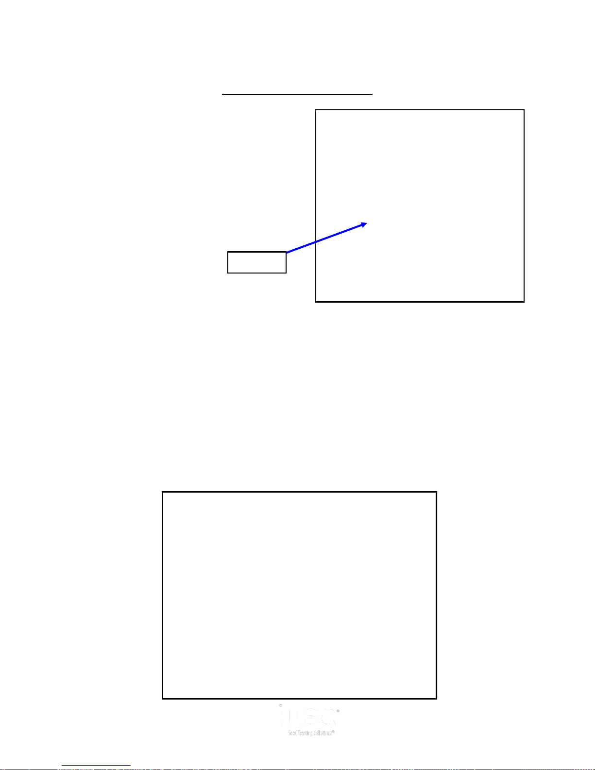
The USB port located on the side of the
operator control panel allows the operator to
download reports to a compact flash device.
USB Port
Use the following steps to upload reports to a computer.
1. Insert a Compact Flash device into the USB port. The Flash device must be in
Fat 32 format.
2. Advance to the Tools & Options screen
3. Press the SEND REPORTS TO USB button. A confirmation window will appear.
Press the YES button and all the reports will automatically copy to the compact
flash device.
4. Remove the compact flash device from the control panel and insert into your
computer.
Page 57
Page 58
LPX AUTOMATED SEED TREATER
DOWNLOADING REPORTS
5. Start Microsoft Office Excel. From the top menu select DATA then FROM TEXT.
6. From the Input Text File screen select the appropriate external drive. Then select
the folders USR / LOG. Change the file type to ALL FILES. Select the file you want to
work with and the Text Import Wizard window will open.
FROM TEXT DATA
EXTERNAL DRIVE
Page 58
FILE TYPE
Page 59

LPX AUTOMATED SEED TREATER
DOWNLOADING REPORTS
7. Under Original data type select Delimited. Change Start import row to 3, then click
Next.
8. Under Delimiters deselect Tab and select Comma. Then click Next.
Page 59
Page 60
LPX AUTOMATED SEED TREATER
DOWNLOADING REPORTS
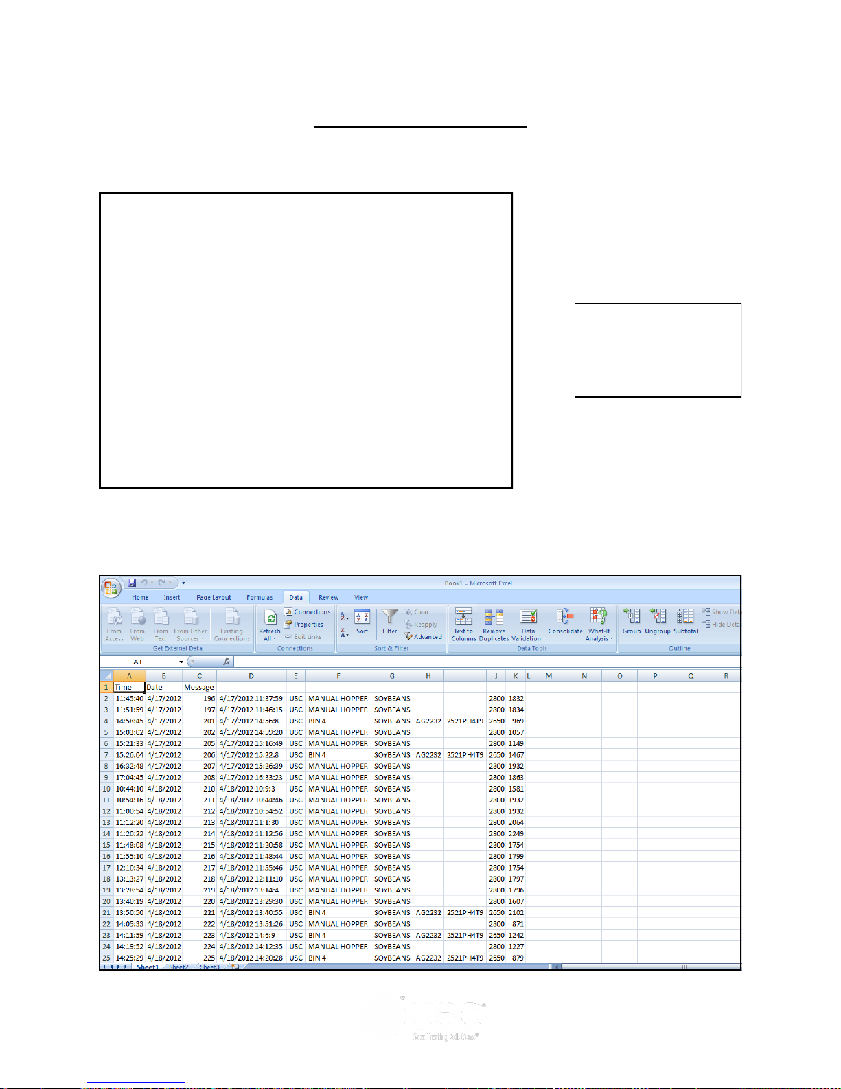
9. Click Finish and the Import Data window appears. Click OK.
10. The Report conversion process is complete. In the File menu, click Save As and
file the report.
Page 60
Page 61

LPX AUTOMATED SEED TREATER
Section
Section
Troubleshooting & Alarms
Troubleshooting & Alarms
FF
TROUBLESHOOTING
Below is a table describing the most frequent problems and solutions with the USC
LPX Automated Seed Treater. For further assistance, contact your local USC dealer.
Problem Possible Cause Solution
Inlet Conveyor will not turn on. 1. Inlet Conveyor proximity
switch is activated.
2. Inlet Conveyor proximity
switch is too sensitive.
3. Conveyor is plugged into
wrong outlet on seed treater
panel.
Pump will not turn off in “AUTO”
when seed runs out.
Pump will not turn on in “AUTO”. 1. Proximity switch is not
1. Proximity switch is dirty.
2. Proximity switch is set too
sensitive.
staying covered.
2. Proximity switch is not
sensitive enough.
1. Clean proximity switch.
2. Adjust the Inlet Conveyor
proximity switch sensitivity by
turning the adjustment screw
counter-clockwise (page 63).
3. Check to make sure the Inlet
Conveyor is plugged into the
inlet conveyor receptacle.
1. Clean proximity switch.
2. Adjust the pump proximity
switch sensitivity by turning
adjustment screw counterclockwise (page 63).
1. Make sure proximity switch is
staying covered with seed.
2. Adjust pump proximity switch
sensitivity by turning the
adjustment screw clockwise
(page 63).
Inlet conveyor won’t shut off
when supply hopper is full.
1. Seed is not hitting proximity
switch.
2. Proximity switch is not set
sensitive enough.
3. Inlet Conveyor is plugged
into wrong receptacle.
1. Make sure seed is hitting
proximity switch.
2. Adjust the inlet conveyor
proximity switch by turning
the adjustment screw
clockwise (page 63).
3. Make sure Inlet Conveyor is
plugged inlet conveyor
receptacle.
Page 61
Page 62

LPX AUTOMATED SEED TREATER
Problem Possible Cause Solution
Pump is fluctuating. 1. Restriction in tubing
2. Filter is plugged or missing
gasket.
Seed calibration is fluctuating. 1. Seed treater supply hopper is
not staying full.
2. Restriction in the supply
hopper or seed wheel.
3. Build-up in the atomizing
chamber.
Drum is slipping and seed is
coming out the inlet side of the
drum.
1. Drum is wet.
2. The seed treater is set too
level.
3. Chains are too loose.
1. Flush tubing and check filter
for any restrictions.
2. Clean filter and check for
gasket.
1. Make sure the supply hopper
and seed wheel are staying
full. May have to lower seed
flow rate in order to have a
consistent flow of seed.
2. Check supply hopper and
seed wheel for any debris,
and remove.
3. Remove atomizing housing
and clean out any build-up of
material.
1. Dry off any moisture that may
have collected on the outside
of the drum.
2. Adjust the slope of the seed
treater to at least a 3” drop
from front to back. If desired,
more slope can be applied.
3. Check and tighten the drive
chains. Also check the chain
alignment.
None of the motors will turn to
“ON” in “HAND” mode.
E-stop is flashing. 1. An E-stop may be
Page 62
1. Processor is faulted.
2. Emergency Stop button is
activated.
depressed.
2. Power may not be on to the
control panels.
3. One of the control panels
may not be connected to all
of the others.
1. Disconnect power and wait
30 seconds before
reconnecting power.
2. Pull out the emergency stop
button.
1. Ensure all E-stops are not
depressed.
2. Check incoming power to
each control panel.
3. Check the wiring and
connections to each
control panel.
Page 63
LPX AUTOMATED SEED TREATER
PROXIMITY SWITCH ADJUSTMENT GUIDE
The proximity switches mounted in the extension ring and the seed wheel detect when
seed is present.
The proximity switch located in the extension ring is used to automatically shut off the
inlet conveyor when the surge hopper is full. This proximity switch is not present on
tower systems.
The proximity switches located in the seed wheel automatically shut off the pump when
all seed has left the hopper.
If the proximity switch is not working properly, this can be caused by wear, dust, or
even moisture. The first step is to clean the lens of the proximity switch. If this does
not solve the problem, the next step would be to adjust the sensitivity of the proximity
switch.
The green light indicates the power status. If it is active the device is powered.
The amber light indicates when seed is being detected. If it is active it detects seed, if
inactive it does not detect seed.
Using the small screwdriver provided inside the control panel, you can adjust the
proximity switch by turning the adjusting screw on the back of the proximity switch.
Turn Clockwise to make the proximity switch more sensitive.
Turn Counterclockwise to make the proximity switch less sensitive.
Proximity Switch Screwdriver
Sensitivity
Adjustment Screw
Amber light Green light
Page 63
Page 64
LPX AUTOMATED SEED TREATER
SYSTEM ALARMS - FAULTS
The table below and on the following pages provides a general description of all the
system alarms (faults & warnings) of the LPX Automated Seed treater. When a fault or
warning condition is detected by the system, the alarms screen will pop-up describing
the cause of the alarm or fault. Any motor fault will activate the alarm screen on the
operator control panel. If running, the system will then progress to the pause state.
A warning will alert the operator of a system condition which needs attention or
correction. The alarms are reset when the fault condition is cleared and the “Reset
Alarm” button is pressed. The horn is silenced by pressing the “Silence Alarm” button
on the alarm screen. For further assistance, contact your local USC dealer.
Clear All Faults
Button
Alarm - Fault Possible Cause Solution
Drum Motor Fault
Seed Wheel Fault
1. No signal from Drum motor
drive (VFD) indicating that
the Drum is running.
2. Drum motor has been
shutdown while in Auto
mode of operation.
1. No signal from Seed Wheel
motor drive (VFD) indicating
that the Seed Wheel is
running.
2. Seed Wheel motor has been
shutdown while in Auto mode
of operation.
Silence Horn
Button
1. Verify that the VFD is
powered up, or check if it is
faulted out. Check the
Information screen.
2. Verify that the Drum was not
turned “Off” while the system
was in Auto mode of
operation.
1. Verify that the VFD is
powered up, or check if it is
faulted out. Check the
Information screen.
2. Verify that the Seed Wheel
was not turned “Off” while the
system was in Auto mode of
operation.
Page 64
Page 65

LPX AUTOMATED SEED TREATER
Alarm - Fault Possible Cause Solution
Atomizer Motor Fault
Pump Motor Fault
Inlet Conveyor Motor Fault Inlet Conveyor motor auxiliary
Outlet Conveyor Motor Fault Outlet Conveyor motor auxiliary
1. No signal from Atomizer
motor drive (VFD) indicating
that the Atomizer is running.
2. Atomizer motor has been
shutdown while in Auto mode
of operation.
Pump motor has been shutdown
while in Auto mode of operation.
contact was not sensed after
being energized to run.
contact was not sensed after
being energized to run.
1. Verify that the VFD is
powered up, or check if it is
faulted out.
2. Verify that the Atomizer was
not turned “Off” while the
system was in Auto mode of
operation.
Verify that the Pump was not
turned “Off” while the system was
in Auto mode of operation.
Verify that the motor starter has
power and is turned on.
Verify that the motor starter has
power and is turned on.
Pump - Not In Process: Valve of the liquid displayed
failed to divert to process when
requested.
Seed Wheel - Lbs/Min Under
Range
Actual Lbs/Min is under 95% of
target rate.
Verify valve has diverted, if so
troubleshoot sensor, if not check
air supply and signal to valve.
Make sure the VFD is not maxed
out at the specified target rate.
Check for sluggish or oscillating
Seed Wheel response. Call the
manufacturer.
Page 65
Page 66

LPX AUTOMATED SEED TREATER
Alarm - Fault Possible Cause Solution
Check Operation Of Seed
Sensors In Seed Wheel
SURGE SUPRESSOR - L1
FAILED!!!
Seed Wheel is in Auto mode of
operation, and only one proximity
sensor has been activated for the
past ten seconds.
L1 of the Surge Protector will no
longer protect the electrical panel
against voltage surges.
Verify both proximity sensors are
working properly. (This alarm will
also be activated if seed is only
flowing through one side of the
seed wheel.)
Replace the Surge Protector.
Page 66
Page 67
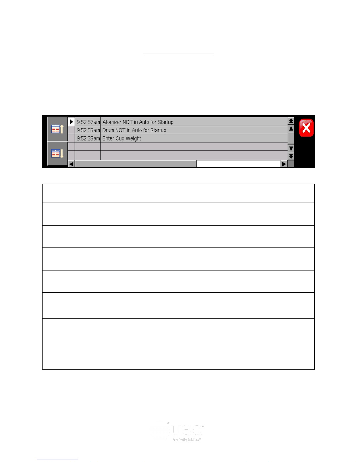
LPX AUTOMATED SEED TREATER
SYSTEM MESSAGES
The table below provides a general description of some of the system messages that
could occur. When a warning condition is detected, a window will appear (below)
notifying the operator that the system will not start because of a certain condition.
When the condition has been corrected, the “START” button can be pressed to start
the system.
Message
Atomizer Not In Auto For Startup
Seed Wheel Not In Auto For Startup:
Drum Not In Auto For Startup
Enter Cup Weight
Current settings EXCEED maximum treater capacity. Check "target treating rate" and "cup weight"
settings.
Current settings are below minimum treater capacity. Check "target treating rate" and "cup weight"
settings.
“Treater Reports - almost FULL. Transfer reports to USB.”
Page 67
Page 68

LPX AUTOMATED SEED TREATER
Section
Section
Maintenance
GG
Maintenance
Proper maintenance of the LPX Automated Seed Treater is critical for peak
performance, reliability and accuracy of this system. The following is a guideline for
the type of maintenance and servicing that should be performed on this unit. Your
environment and uses may require additional maintenance and service beyond this list
to assure a reliable and safe unit. The operator of this unit has ultimate responsibility
to identify areas of concern and rectify them before they become a hazard or safety
issue. There is no substitute for a trained, alert operator.
Do not put this unit into operation with any questionably
maintained parts. Poor performance or a hazard may occur.
DRIVE AND DRUM
Inspect all welds and structural components on frame and drum for bends,
cracks and damage.
Remove shields and inspect pillow block bearings.
Inspect drive wheels for unordinary wear, and setscrews for tightness.
Inspect the Neoprene idler wheels.
Tighten and lubricate chain.
PUMPS AND PLUMBING
Check pump in forward and reverse.
Make sure pump heads open and close smoothly.
Inspect tubing and for uneven wear. Replace pump tubing often to ensure high
flow rates can be met.
Check air actuated 3-way valve . Clean brass filter if necessary
Tighten hose clamps and check filter. Clean filter frequently to avoid blockages
Flush flow meter with clean water frequently to avoid chemical buildup.
SEED WHEEL
Inspect all welds and structural components for bends, cracks and damage.
Remove shields to inspect wheel, brushes and proximity switches.
Use compressed air to blow out any seeds and excess build-up that may have
occurred during operation.
Page 68
Page 69
LPX AUTOMATED SEED TREATER
ATOMIZER
To access inside of atomizer housing, push up on the quick release handle and slide
back the atomizer (below).
Atomizer Head
Slide back atomizer housing and grease
bearing inside. Bearing needs just one
pump of grease every 40 hours of use
(right).
Clean any build-up inside the housing and
the atomizer head. To remove the
atomizer head, loosen the set screw
located on the bottom of the head.
Check for any play in the atomizer shaft.
Make sure the atomizer spins smoothly.
Quick-Release
Handle
Ensure the adjustable chute is fitting
completely into the drum opening.
Adjust if necessary.
Set Screw Bearing
Page 69
Page 70

LPX AUTOMATED SEED TREATER
MIX TANK
Check motor.
Check for any play in the mix tank shaft.
Check valves, fittings, and plug on bottom of tank for leaks.
Check chemical line tubing for abnormal wear.
ELECTRICAL PANEL
Check and tighten wire connections.
Check quick connects on bottom of control panel.
Check starters and overloads.
Check relays and breakers.
Check and set the proximity switches. (page 63).
Check VFD’s.
Page 70
Page 71
LPX AUTOMATED SEED TREATER
Section
Section
Storage
Storage
When storing the USC LPX Automated Seed Treater for long periods of time, the
following procedure must be followed to reduce the chance of rust, corrosion and
fatigue of the treater. You can also use these steps when storing the machine for the
winter.
1. Turn power off to the treater and treater components.
2. Remove shields from the seed wheel and remove any debris or build-up.
Compressed air can be used to blow out any foreign material.
3. Turn power back on to the treater and run seed wheel to help remove any
additional debris. Compressed air can be used to blow out any foreign material.
A dust mask and protective rubber gloves shall be used when
cleaning the machine.
SEEDWHEEL & SUPPLY HOPPER
HH
4. Check brushes for wear (below).
5. Wipe off and clean the lens of the proximity switches (below).
6. Disconnect power and mount all guard back in place.
7. Tarp or cover the supply hopper and seed wheel to keep out any dirt or unwanted
pests.
Proximity Switch
Encoder Brush
Page 71
Page 72

LPX AUTOMATED SEED TREATER
ATOMIZER CHAMBER
1. Remove and clean the atomizer
housing.
2. Remove the atomizer head and
stainless steel plumbing. The
atomizer head can be disassembled
(right), for easier cleaning. It is
threaded together and can simply be
unscrewed.
3. Reinstall the atomizer head and
plumbing. Grease the bearing and
spin the atomizer head a few times to
ensure all grease has been worked
into the bearings.
LIQUID SYSTEM
1. Make certain the inside of the tank is completely drained of chemical residue and
thoroughly flush the inside of the tank with clean water.
2. Remove and clean the filter.
3. Pump clean water through all areas of the plumbing including the mix tank, flow
meter, and valves. It may be necessary to move the position of the air actuated
3-way valve from recirc to process in order to clean the chemical lines that run to
the seed treater.
4. Open all drain points, valves, and filter
to let as much of the liquid drain as
possible.
5. If the seed treater will be exposed to
possible freezing temperatures, the final
flush of the system should be made with
an non freezable liquid. Or use
compressed air to blow the lines out
from any moisture.
6. Release pump heads (right) and remove
tubing to prevent any unnecessary
wear.
Page 72
Pump Head Open
Page 73

LPX AUTOMATED SEED TREATER
ROTATING DRUM
1. Remove the shields and clean out any seed that may have fallen underneath the
drum.
2. Clean out any residue left on the inside of the drum and around the seed lifters.
3. Lubricate the chain to keep from corroding in storage.
FINAL
1. Store the machine inside a protective building to keep it from being exposed to the
weather.
2. Disconnect power to the machine.
3. Ensure all guards and safety signs are in place.
Page 73
Page 74
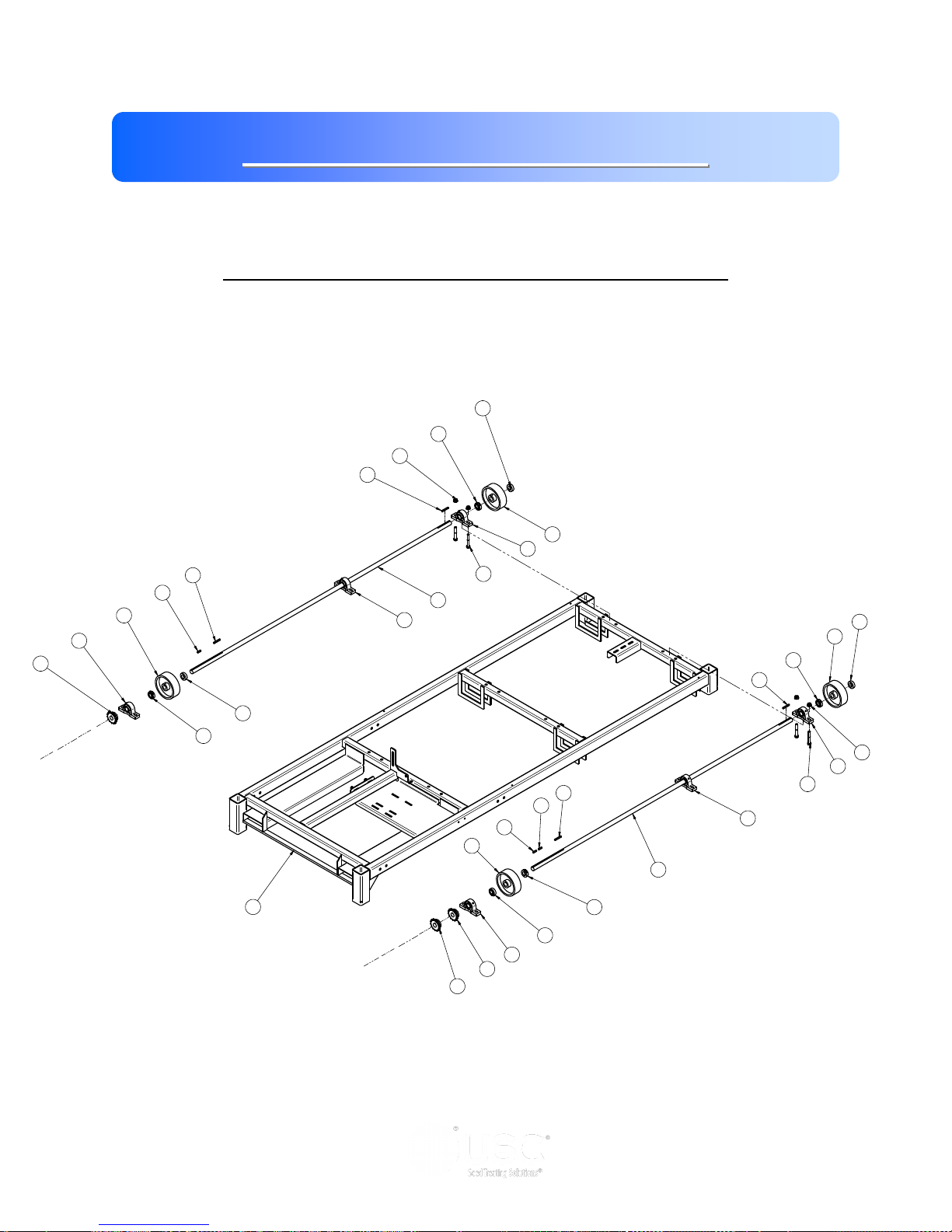
LPX AUTOMATED SEED TREATER
4
11
8
9
9
6
7
6
4
2
2
14
4
18
6
7
6
8
6
6
7
4
18
8
14
11
4
8
9
6
6
7
4
2
22
Section
Section
Mechanical Drawings
II
Mechanical Drawings
The following pages show the parts of the LPX Automated Seed Treater. Please have
the part number ready when ordering parts.
LPX BASE FRAME ASSEMBLY (18-01-0011 & 18-01-0012)
Page 74
Page 75
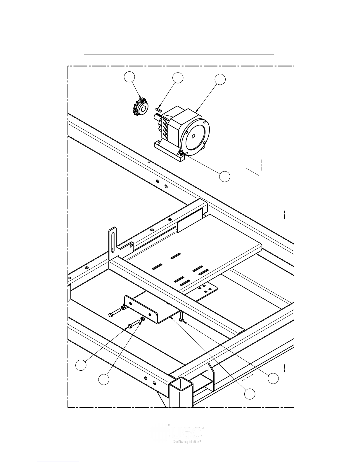
LPX AUTOMATED SEED TREATER
2
9
1
19
16
10
17
15
LPX BASE FRAME ASSEMBLY (18-01-0011 & 18-01-0012)
Page 75
Page 76
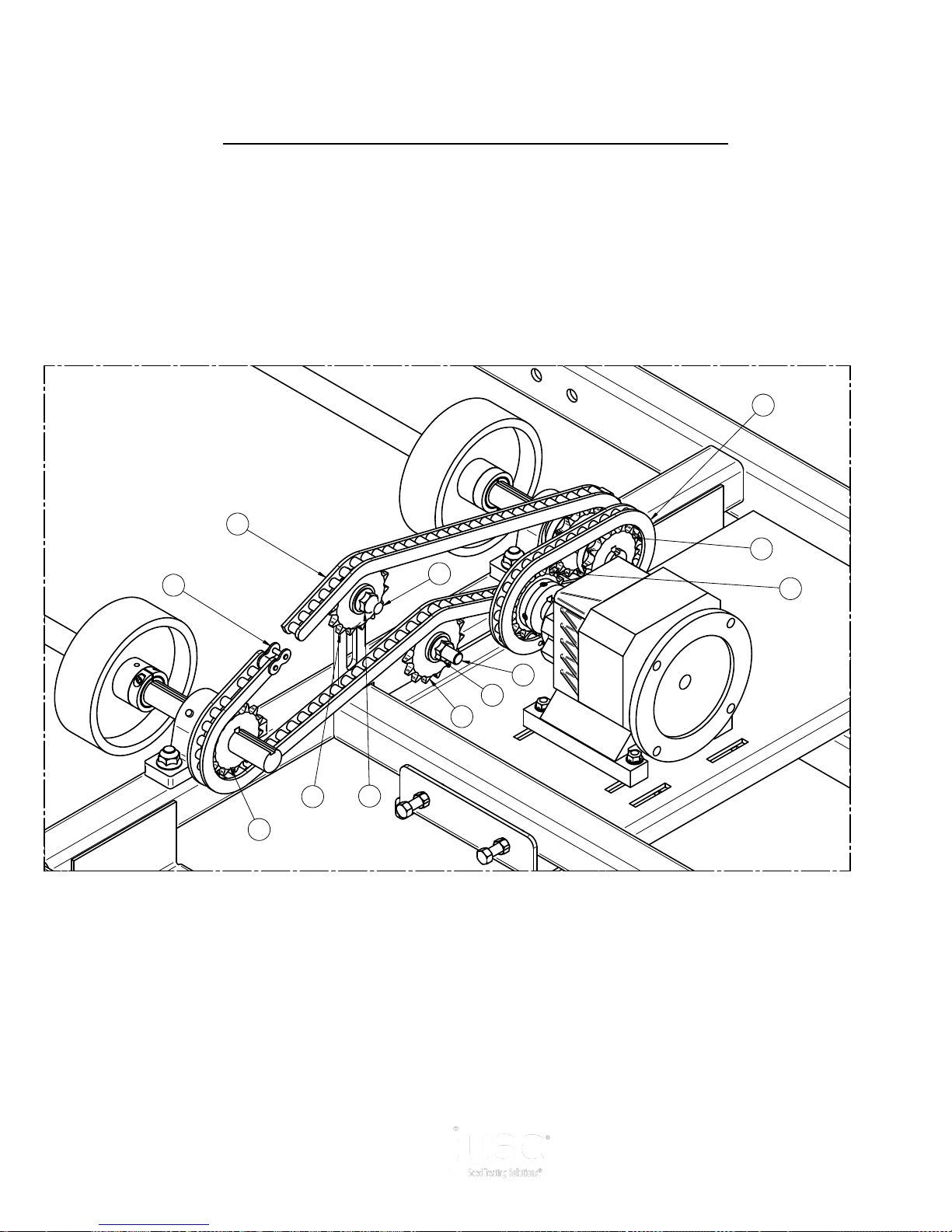
LPX AUTOMATED SEED TREATER
20
5
2
3
18
12
3
18
13
2
21
2
LPX BASE FRAME ASSEMBLY (18-01-0011 & 18-01-0012)
Page 76
Page 77

LPX AUTOMATED SEED TREATER
LPX BASE FRAME ASSEMBLY (18-01-0011 & 18-01-0012)
LPX 6 FT LPX 8 FT
LPX BASE FRAME ASSEMBLY
18-01-0011 18-01-0012
Item # Description Part # Qty Part # Qty
1 GBOX IL 56C 16.2:1 GR B1 FOOT MNT 01-01-0101 1 01-01-0101 1
2 SPROCKET # 50 14T 1.00 IN BORE TYPE B 01-02-0093 4 01-02-0093 4
3 SPKT 17 T 50P .500 ID IDLER 01-02-0095 2 01-02-0095 2
4 BRG PLW 1.00ID STSC SEALED 01-03-0036 6 01-03-0036 6
5 #50 CNTG LINK 01-04-0005 2 01-04-0005 2
6 SHAFT CLR 1.00ID SPLIT 01-05-0008 8 01-05-0008 8
7 WHL DRV 6 X 2 X 1.00ID .250KWY 01-06-0002 4 01-06-0002 4
8 KEY .250 X 2.00 CS 01-10-0003 4 01-10-0003 4
9 KEY .250 X 1.00 CS 01-10-0004 4 01-10-0004 4
10 WDMT DRUM DRV ADJ PLT 05-04-0067 1 05-04-0067 1
11 DRUM DRIVE SHAFT LPX 05-11-0003 2 05-11-0348 2
12 BOLT CRG .500-13 X 2.00 ZP GR5 06-01-0026 1 06-01-0026 1
13 BOLT .500-13 X 2.00 ZP GR5 06-01-0027 1 06-01-0027 1
14 BOLT .500-13 X 3.25 ZP GR5 06-01-0029 12 06-01-0029 12
15 BOLT .375-16 X 2.00 ZP GR5 FULL THRD 06-01-0137 2 06-01-0137 2
16 BOLT CRG .313-18 X 1.75 ZP GR5 06-01-0172 4 06-01-0172 4
17 NUT FULL .375-16 ZP GR5 06-02-0003 2 06-02-0003 2
18 NUT LOCK FLG .500-13 ZP GR5 06-03-0015 14 06-03-0015 14
19 NUT, FLG .3125-18 UNC ZP GRADE 5 06-03-0019 4 06-03-0019 4
20 #50 CHAIN 84LINKS 13-05-0156 1 13-05-0156 1
21 #50 CHAIN -- 32 LINKS 13-05-0157 1 13-05-0157 1
22 WDMT BASE FRAME LPX 18-01-0007 1 18-01-0008 1
Page 77
Page 78
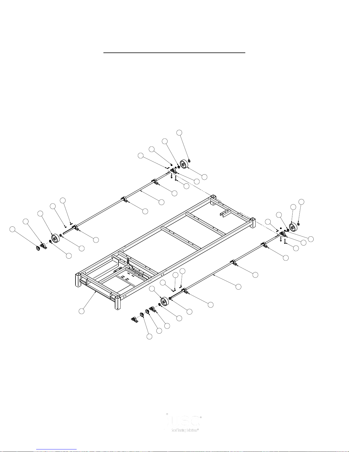
LPX AUTOMATED SEED TREATER
5
13
9
10
10
7
8
7
5
2
2
16
5
20
7
8
7
9
7
7
8
5
20
9
16
12
5
9
10
7
7
8
5
2
25
5
5
5
5
LPX BASE FRAME ASSEMBLY (18-01-0013)
Page 78
Page 79
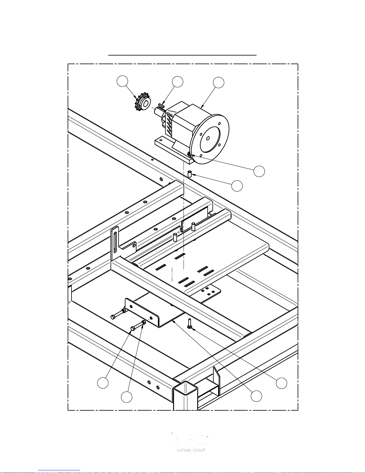
LPX AUTOMATED SEED TREATER
4
10
1
21
18
11
19
17
22
LPX BASE FRAME ASSEMBLY (18-01-0013)
)
Page 79
Page 80
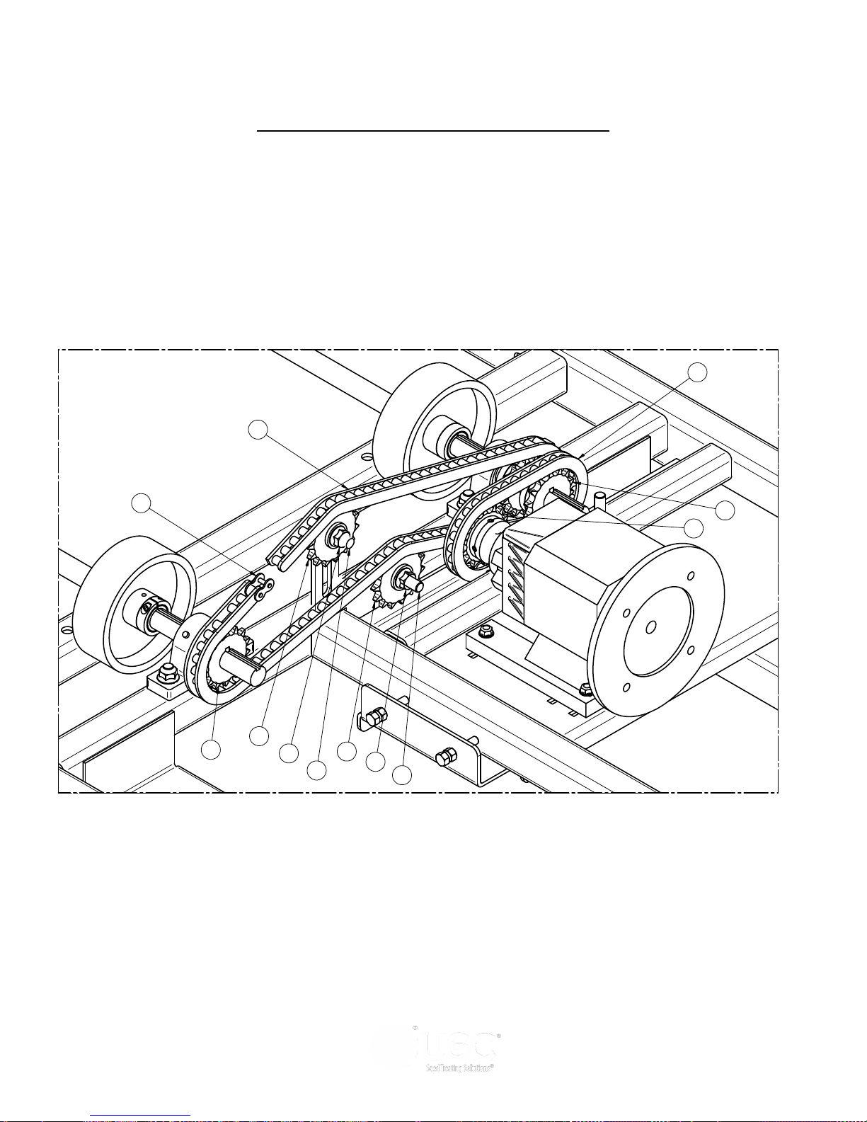
LPX AUTOMATED SEED TREATER
23
6
2
3
20
14
3
20
15
24
24
4
LPX BASE FRAME ASSEMBLY (18-01-0013)
Page 80
Page 81

LPX AUTOMATED SEED TREATER
LPX BASE FRAME ASSEMBLY (18-01-0013)
Item # Part #
1 01-01-0167
GBOX IL 182-4TC 16.6:1 GR B1 FT MNT 1
Description Qty
2 01-02-0093 SPROCKET # 50 14T 1.00 IN BORE TYPE B 3
3 01-02-0095 SPKT 17 T 50P .500 ID IDLER 2
4 01-02-0117 SPROCKET # 50 14T 1.25 IN BORE TYPE B 1
5 01-03-0060 BRG PLW SEALED 1.00ID STSC 11
6 01-04-0005 #50 CNTG LINK 2
7 01-05-0008 SHAFT CLR 1.00ID SPLIT 8
8 01-06-0002 WHL DRV 6 X 2 X 1.00ID .250KWY 4
9 01-10-0003 KEY .250 X 2.00 CS 4
10 01-10-0004 KEY .250 X 1.00 CS 4
11 05-04-0067 WDMT DRUM DRV ADJ PLT 1
12 05-11-0235 DRUM DRIVE SHAFT LX2000 +4 108" 1
13 05-11-0387 DRUM DRIVE SHAFT LPX 10FT EXT 1
14 06-01-0026 BOLT CRG .500-13 X 2.00 ZP GR5 1
15 06-01-0027 BOLT .500-13 X 2.00 ZP GR5 1
16 06-01-0029 BOLT .500-13 X 3.25 ZP GR5 20
17 06-01-0137 BOLT .375-16 X 2.00 ZP GR5 FULL THRD 2
18 06-01-0172 BOLT CRG .313-18 X 1.75 ZP GR5 4
19 06-02-0003 NUT FULL .375-16 ZP GR5 2
20 06-03-0015 NUT LOCK FLG .500-13 ZP GR5 24
21 06-03-0019 NUT, FLG .3125-18 UNC ZP GRADE 5 4
22 102D70 BUSH 10FT LPX GBOX MNT 4
23 13-05-0156 #50 CHAIN 84LINKS 1
24 13-05-0157 #50 CHAIN -- 32 LINKS 1
25 18-01-0009 WDMT BASE FR LPX 10 FT 1
Page 81
Page 82
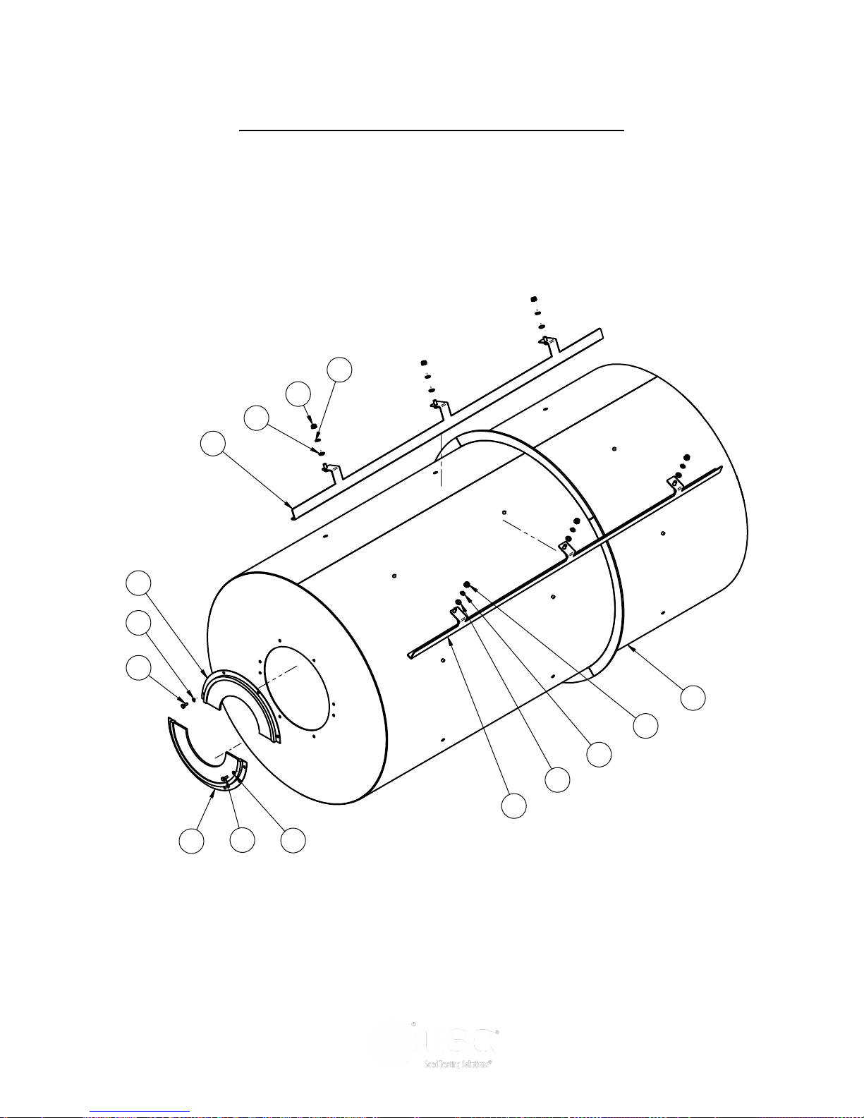
LPX AUTOMATED SEED TREATER
7
9
5
3
2
8
5
3
2
6
6
1
4
1
4
LPX800 & LPX2000 6 FOOT DRUM ASSEMBLYS
Page 82
Page 83
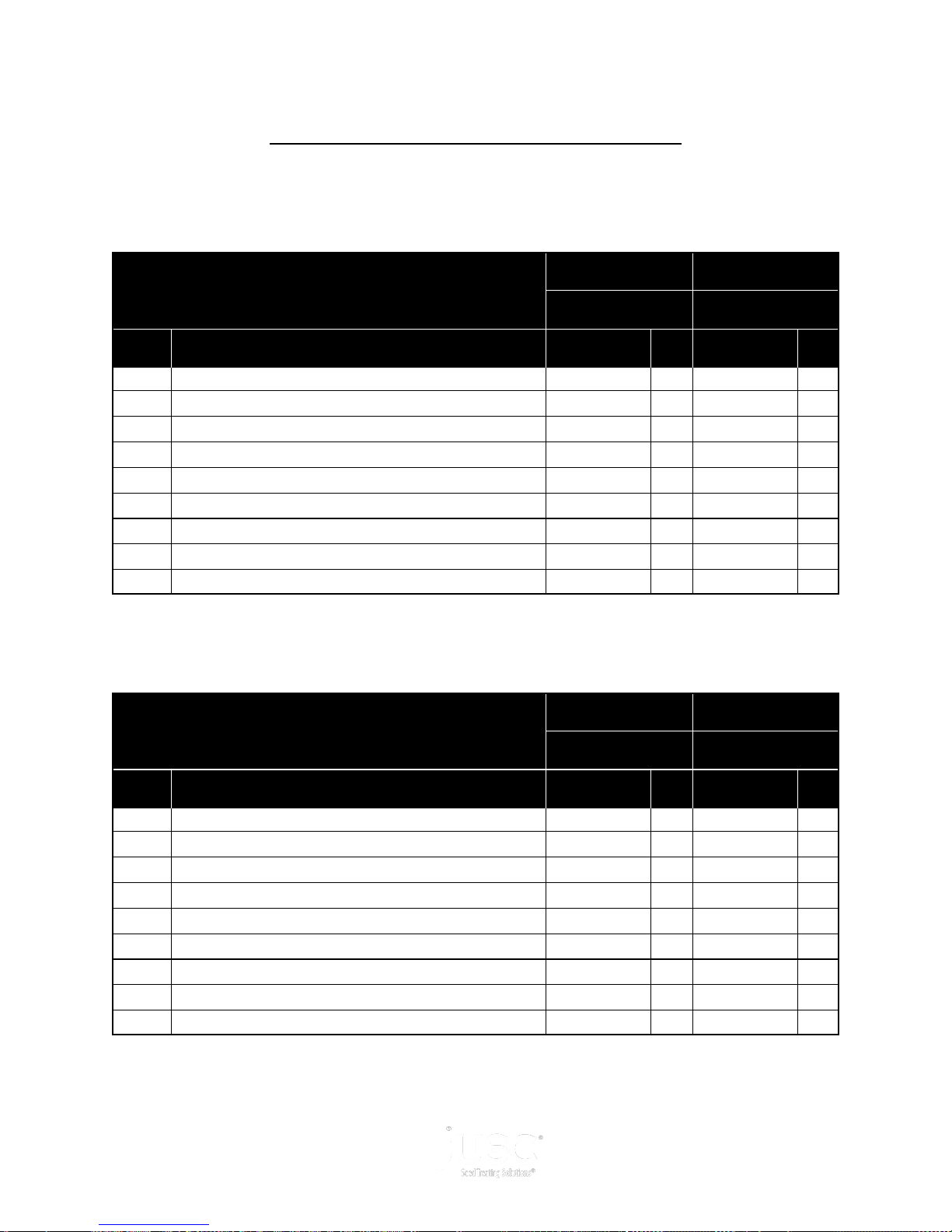
LPX AUTOMATED SEED TREATER
LPX800 & LP2000 6 FOOT DRUM ASSEMBLYS
LPX800 6FT CS LPX800 6FT SS
LPX800 DRUM ASSEMBLY
18-01-0042 18-01-0043
Item # Description Part # Qty Part # Qty
1 BOLT .250-20 X .75 UNC ——— — ——— —
2 NUT .375-16 06-03-0014 24 06-02-0010 24
3 WASHER, LOCK, SPLIT .375 SS ——— — 06-04-0008 24
4 WASHER, LOCK, SPLIT .250 ——— — ——— —
5 WASHER, SS, BONDED, SEALING .375 ID 06-04-0013 24 06-04-0013 24
6 SEAL, BRUSH, 180 DEG 7.80 OR X 4.00 IR ——— — ——— —
7 WELDMENT, DRUM 18-01-0016 1 18-01-0129 1
8 WELDMENT, DRUM PADDLE, TALL 18-01-0026 4 18-01-0027 4
9 WELDMENT, DRUM PADDLE, SHORT 18-01-0034 4 18-01-0035 4
LPX2000 6FT CS LPX2000 6FT SS
LPX2000 DRUM ASSEMBLY
18-01-0044 18-01-0045
Item # Description Part # Qty Part # Qty
1 BOLT .250-20 X .75 UNC 06-01-0006 8 06-01-0006 8
2 NUT .375-16 06-03-0014 24 06-02-0010 24
3 WASHER, LOCK, SPLIT .375 SS ——— — 06-04-0008 24
4 WASHER, LOCK, SPLIT .250 06-04-0001 8 06-04-0009 8
5 WASHER, SS, BONDED, SEALING .375 ID 06-04-0013 24 06-04-0013 24
6 SEAL, BRUSH, 180 DEG 7.80 OR X 4.00 IR 06-10-0018 2 06-10-0018 2
7 WELDMENT, DRUM 18-01-0018 1 18-01-0019 1
8 WELDMENT, DRUM PADDLE, TALL 18-01-0026 4 18-01-0027 4
9 WELDMENT, DRUM PADDLE, SHORT 18-01-0034 4 18-01-0035 4
Page 83
Page 84
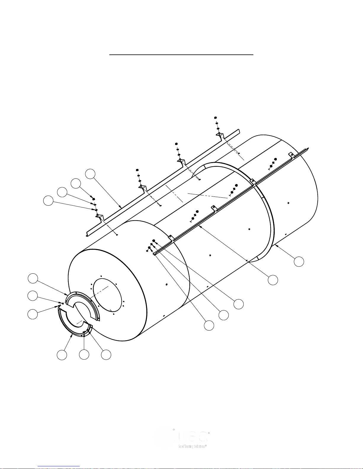
LPX AUTOMATED SEED TREATER
9
2
3
5
4
1
4
1
6
6
7
8
2
3
5
LPX2000 8 & 10 FOOT DRUM ASSEMBLYS
Page 84
Page 85
LPX AUTOMATED SEED TREATER
LPX2000 8 & 10 FOOT DRUM ASSEMBLYS
LPX2000 8FT CS LPX2000 8FT SS
LPX DRUM ASSEMBLY
18-01-0046 18-01-0047
Item # Description Part # Qty Part # Qty
1 BOLT .250-20 X .75 UNC 06-01-0006 8 06-01-0006 8
2 NUT .375-16 06-03-0014 32 06-02-0010 32
3 WASHER, LOCK, SPLIT .375 SS ——— — 06-04-0008 32
4 WASHER, LOCK, SPLIT .250 06-04-0001 8 06-04-0009 8
5 WASHER, SS, BONDED, SEALING .375 ID 06-04-0013 32 06-04-0013 32
6 SEAL, BRUSH, 180 DEG 7.80 OR X 4.00 IR 06-10-0018 2 06-10-0018 2
7 WELDMENT, DRUM 18-01-0187 1 18-01-0186 1
8 WELDMENT, DRUM PADDLE, SHORT 18-01-0192 4 18-01-0193 4
9 WELDMENT, DRUM PADDLE, TALL 18-01-0194 4 18-01-0195 4
LPX2000 10FT CS LPX2000 10FT SS
LPX DRUM ASSEMBLY
18-01-0048 18-01-0049
Item # Description Part # Qty Part # Qty
1 BOLT .250-20 X .75 UNC 06-01-0006 8 06-01-0006 8
2 NUT .375-16 06-03-0014 40 06-02-0010 40
3 WASHER, LOCK, SPLIT .375 SS ——— — 06-04-0008 40
4 WASHER, LOCK, SPLIT .250 06-04-0001 8 06-04-0009 8
5 WASHER, SS, BONDED, SEALING .375 ID 06-04-0013 40 06-04-0013 40
6 SEAL, BRUSH, 180 DEG 7.80 OR X 4.00 IR 06-10-0018 2 06-10-0018 2
7 WELDMENT, DRUM 18-01-0188 1 18-01-0189 1
8 WELDMENT, DRUM PADDLE, SHORT 18-01-0196 4 18-01-0197 4
9 WELDMENT, DRUM PADDLE, TALL 18-01-0198 4 18-01-0199 4
Page 85
Page 86
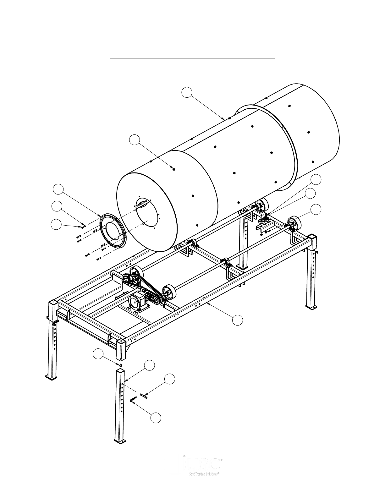
LPX AUTOMATED SEED TREATER
37
20
33
55
23
40
29
22
3
29
10
35
36
LPX AUTOMATED TREATER (Drum and Legs)
Page 86
Page 87
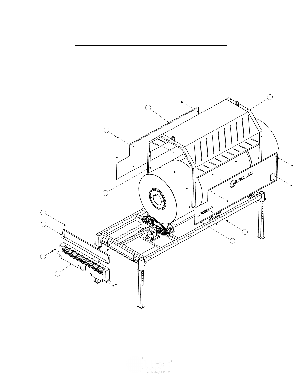
LPX AUTOMATED SEED TREATER
THIS MATERIAL IS THE CONFIDENTIAL AND PROPRIETARY PR OPERTY OF
USC, LLC. AND SHALL NOT BE USED WITHOUT PERMISSION.
THIS MATERIAL IS THE CONFIDENTIAL AND PROPRIETARY PR OPERTY OF
USC, LLC. AND SHALL NOT BE USED WITHOUT PERMISSION.
DRAWN
CHECKED
ENG APPR
NAME
davidw
11/20/2012
UNLESS OTHERWISE SPECIFIED DIMENSIONS ARE IN
INCHES:
TOLERANCES:
FRACTIONS DECIMALS ANGLES
DRAWN
CHECKED
ENG APPR
NAME
davidw
11/20/2012
UNLESS OTHERWISE SPECIFIED DIMENSIONS ARE IN
INCHES:
TOLERANCES:
FRACTIONS DECIMALS ANGLES
51
25
25
41
50
25
13
25
11
25
LPX AUTOMATED TREATER (Drum and Drive Guards)
Page 87
Page 88
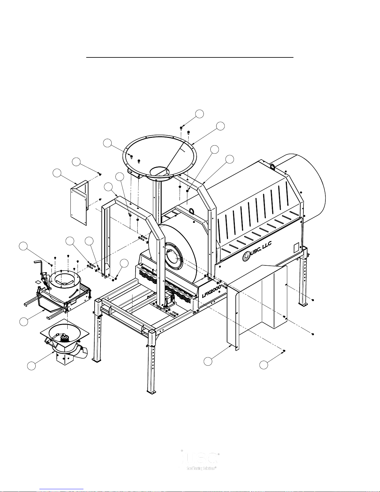
LPX AUTOMATED SEED TREATER
46
30
28
16
25
28
30
49
47
43
25
34
24
44
54
30
25
LPX AUTOMATED TREATER (Inlet and Atomizer Chamber)
Page 88
Page 89
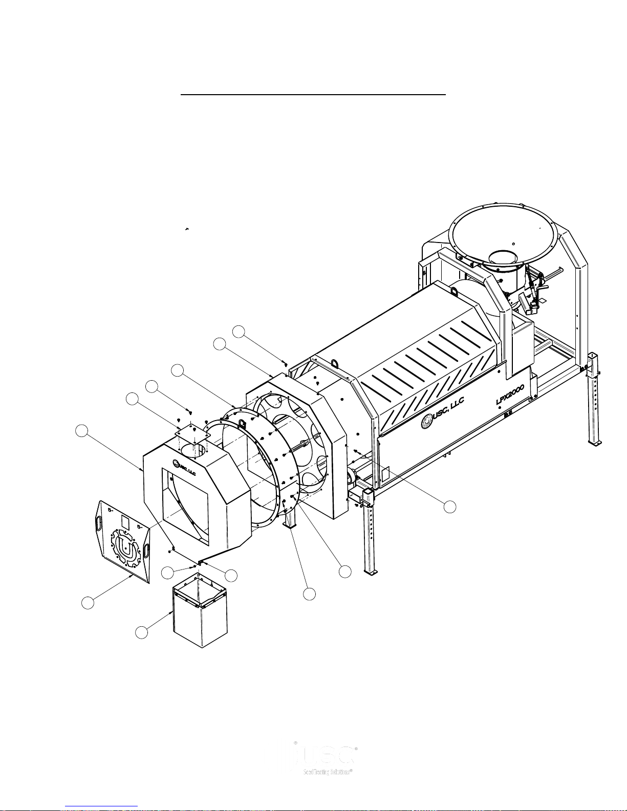
LPX AUTOMATED SEED TREATER
48
25
25
42
25
25
53
19
25
12
45
26
31
LPX AUTOMATED TREATER (Discharge End)
Page 89
Page 90
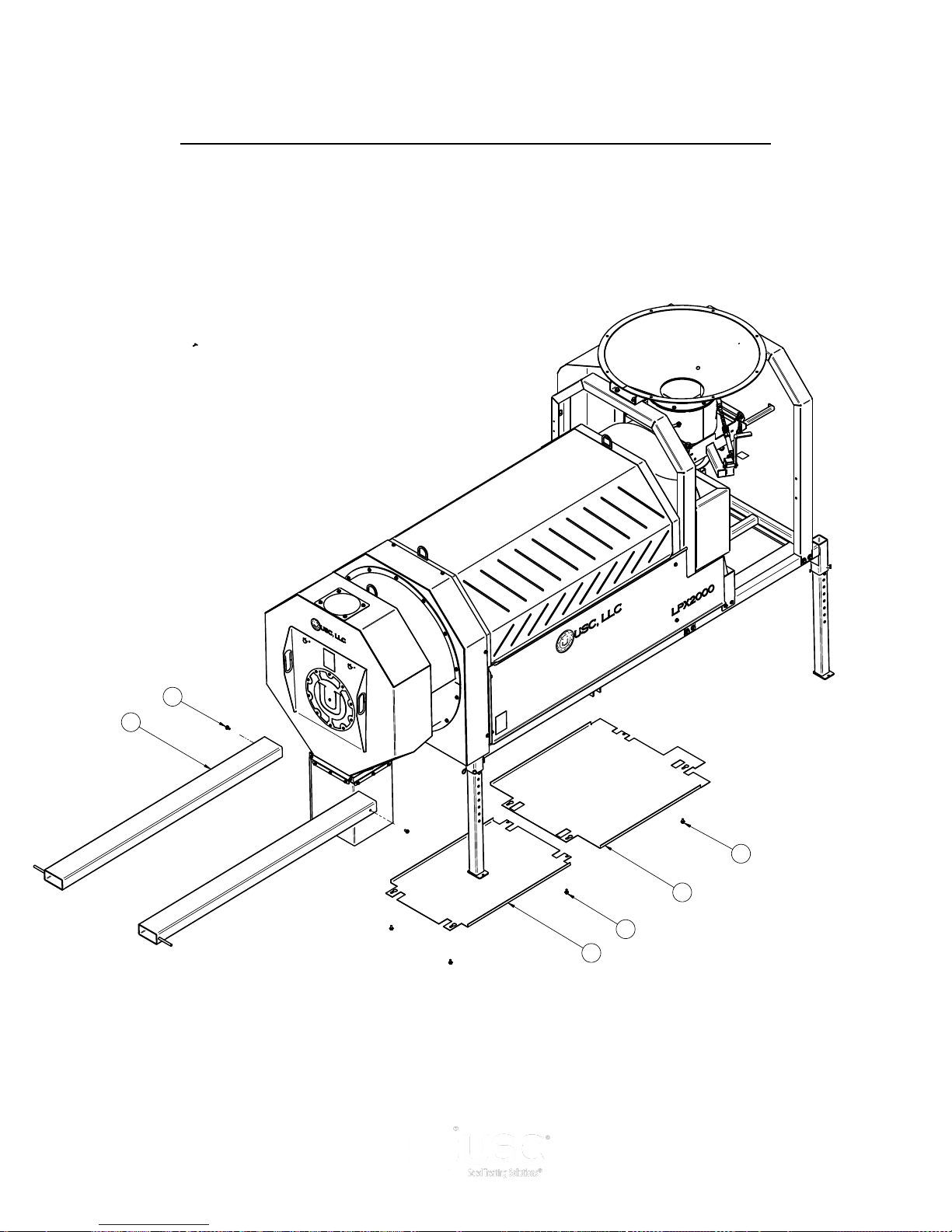
LPX AUTOMATED SEED TREATER
52
25
18
25
25
17
LPX AUTOMATED TREATER (Forklift Pockets and Bottom Guards)
Page 90
Page 91
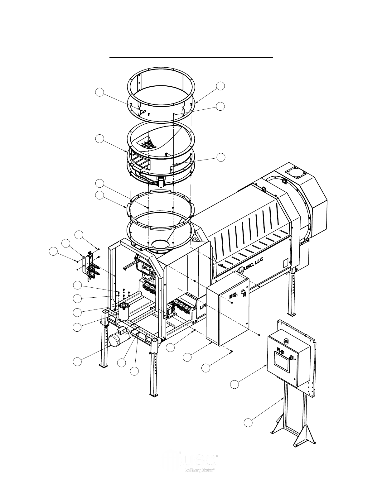
1
32
21
2
32
21
9
14
38
5
27
29
39
29
15
8
29
25
7
29
25
6
LPX AUTOMATED SEED TREATER
LPX AUTOMATED TREATER (Final Assembly)
Page 91
Page 92

LPX AUTOMATED SEED TREATER
LPX AUTOMATED TREATER
LPX 800 LPX 2000
TREATER
6 FOOT 6 FOOT
Item # Description Part # Qty Part # Qty
1 MTR .33HP 1725RPM 56C TENV SEE TABLE 1 1 SEE TABLE 1 1
2 MTR 1.5HP 1725RPM 56C TENC SEE TABLE 2 1 SEE TABLE 2 1
3 WHL GUIDE .375ID X 2.50 X .875 NPRN 01-06-0004 2 01-06-0004 2
4 PLUG STEEL 22MM 03-08-0130 1 03-08-0130 1
5 SENS PROX 24-240 AC AB 875CPG8N18A2 03-10-0051 1 03-10-0051 1
6 PANEL CONTROL MAIN LPX TREATER 03-12-0150 1 03-12-0150 1
7 PANEL CONTROL LPX TREATER (6 & 8 FOOT DRUMS) SEE TABLE 3 1 SEE TABLE 3 1
7* PANEL CONTROL LPX TREATER (10 FOOT DRUM) SEE TABLE 4 1 SEE TABLE 4 1
8 ASSY STATIC MIXER LPX TREATER 04-03-0157 1 04-03-0157 1
9 BIN SITE MAIN CNTL PNL FLOOR STAND 05-03-0580 1 05-03-0580 1
10 WDMT ADJ TREATER LEG 05-05-0001 4 05-05-0001 4
11 WDMT CHAIN GRD LPX 05-06-0001 1 05-06-0001 1
12 ASSY END CHUTE DOOR 05-07-0198 1 05-07-0198 1
12* ASSY END CHUTE DOOR (STAINLESS STEEL) 05-07-0530 1 05-07-0530 1
13 GRD DRUM INLET LOWER 05-10-0150 1 05-10-0150 1
14 DISK ATOMIZER MOTOR 05-10-0805 1 05-10-0805 1
15 SEAL BETWEEN FLANGES SMW TO TRTR 05-10-2463 4 05-10-2463 4
16 GRD DRUM INLET LPX BOLTED 05-10-3931 1 05-10-3931 1
17 GRD DRUM BTM FRNT HALF LPX 05-10-3950 1 05-10-3950 1
18 GRD DRUM BTM REAR HALF LPX 05-10-3951 1 05-10-3951 1
19 PLT CVR TREATER DSCHG 05-10-3800 1 05-10-3800 1
19* PLT CVR TREATER DSCHG (STAINLESS STEEL) 05-10-4032 1 05-10-4032 1
20 BOLT, .250-20 X .750 UNC 18-8 06-01-0006 8 06-01-0006 8
20* BOLT, .250-20 X .750 UNC 18-8 (STAINLESS STEEL) 06-01-0003 8 06-01-0003 8
21 BOLT .375-16 X 1.00 ZP GR5 06-01-0016 16 06-01-0016 16
22 BOLT .375-16 X 1.75 ZP GR5 06-01-0019 2 06-01-0019 2
23 BOLT .500-13 X .750 ZP GR5 06-01-0024 4 06-01-0024 4
24 BOLT .500-13 X 3.25 ZP GR5 06-01-0029 8 06-01-0029 8
25 BOLT, FLG .375-16 UNC ZP GRADE 5; 3/4" LG 06-01-0124 82 06-01-0124 82
26 BOLT CRG .3125-18X.750 ZP SHORT NECK 06-01-0171 4 06-01-0171 4
27 BOLT, FLG .375-16 UNC ZP GRADE 5; 1-1/4" LG 06-01-0189 8 06-01-0189 8
28 BOLT FLG .500-13 X 1.250 ZP GR5 06-01-0232 4 06-01-0232 4
29 NUT LOCK FLG .375-16 ZP GR5 06-03-0014 62 06-03-0014 62
Page 92
Page 93

LPX AUTOMATED SEED TREATER
LPX AUTOMATED TREATER
LPX 800 LPX 2000
TREATER
6 FOOT 6 FOOT
Item # Description Part # Qty Part # Qty
30 NUT LOCK FLG .500-13 ZP GR5 06-03-0015 12 06-03-0015 12
31 NUT LOCK FLG .3125-18 ZP GR5 06-03-0019 4 06-03-0019 4
32 WSHR LOCK SPLT .375 ZP 06-04-0003 16 06-04-0003 16
33 WASHER, .250 LOCK 316 06-04-0001 8 06-04-0001 8
33* WASHER, .250 LOCK 316 (STAINLESS STEEL) 06-04-0009 8 06-04-0009 8
34 WSHR FLAT .500 ZP 06-05-0005 8 06-05-0005 8
35 PIN CLIP HITCH 3.063 SIZE 9 ZP 06-09-0002 4 06-09-0002 4
36 PIN CLVS .500 X 3.50 PLN 06-09-0005 4 06-09-0005 4
37 SEAL BRSH 180 DEG 7.81 OR X 4.00 IR 06-10-0018 2 06-10-0018 2
38 ASSY EXTENSION HOPPER SEE TABLE 5 1 SEE TABLE 5 1
39 ASSY SEED METER WHEEL 13-04-0064 1 13-04-0065 1
40 ASSY BASE FRAME LPX (SEE PAGES 74-81) 18-01-0011 1 18-01-0011 1
41 WDMT DRUM GRD LPX 18-01-0050 1 18-01-0050 1
42 WDMT DRUM EXT GRD LPX 18-01-0054 1 18-01-0054 1
43 ASSY ADJ CHMBR LPX 18-01-0061 1 18-01-0062 1
44 ASSY ATOMIZER LPX 18-01-0067 1 18-01-0069 1
44* ASSY ATOMIZER LPX (STAINLESS STEEL) 18-01-0068 1 18-01-0070 1
45 ASSY END CHUTE EXTENSION LPX 18-01-0072 1 18-01-0072 1
46 WDMT INLET HOPPER LPX 18-01-0080 1 18-01-0080 1
47 WDMT HEADACHE RACK SHORT 18-01-0081 1 18-01-0081 1
48 WDMT DRUM EXT GRD MNT LPX 18-01-0082 1 18-01-0082 1
49 WDMT HEADACHE RACK TALL 18-01-0083 1 18-01-0083 1
50 ASSY GRD DRUM LPX RT GALV 18-01-0091 1 18-01-0091 1
51 ASSY GRD DRUM LPX LT GALV 18-01-0094 1 18-01-0094 1
52 WDMT FORKLIFT POCKET EXT 18-01-0106 2 18-01-0106 2
53 WDMT END CHUTE LPX 18-01-0057 1 18-01-0057 1
53* WDMT END CHUTE LPX (STAINLESS STEEL) 18-01-0125 1 18-01-0125 1
54 WDMT ENCL MNT LPX LARGE PNL 18-01-0155 1 18-01-0155 1
55 ASSY DRUM LPX (SEE PAGES 82-85) 18-01-0042 1 18-01-0044 1
55* ASSY DRUM LPX-STAINLESS STEEL (SEE PAGES 82-85) 18-01-0043 1 18-01-0045 1
Page 93
Page 94

LPX AUTOMATED SEED TREATER
LPX AUTOMATED TREATER
LPX 2000 LPX 2000
TREATER
8 FOOT 10 FOOT
Item # Description Part # Qty Part # Qty
1 MTR .33HP 1725RPM 56C TENV SEE TABLE 1 1 SEE TABLE 1 1
2 MTR 1.5HP 1725RPM 56C TENC SEE TABLE 2 1 SEE TABLE 2 1
3 WHL GUIDE .375ID X 2.50 X .875 NPRN 01-06-0004 2 01-06-0004 2
4 PLUG STEEL 22MM 03-08-0130 1 03-08-0130 1
5 SENS PROX 24-240 AC AB 875CPG8N18A2 03-10-0051 1 03-10-0051 1
6 PANEL CONTROL MAIN LPX TREATER 03-12-0150 1 03-12-0150 1
7 PANEL CONTROL LPX TREATER (6 & 8 FOOT DRUMS) SEE TABLE 3 1 SEE TABLE 3 1
7* PANEL CONTROL LPX TREATER (10 FOOT DRUM) SEE TABLE 4 1 SEE TABLE 4 1
8 ASSY STATIC MIXER LPX TREATER 04-03-0157 1 04-03-0157 1
9 BIN SITE MAIN CNTL PNL FLOOR STAND 05-03-0580 1 05-03-0580 1
10 WDMT ADJ TREATER LEG 05-05-0001 4 05-05-0001 4
11 WDMT CHAIN GRD LPX 05-06-0001 1 05-06-0001 1
12 ASSY END CHUTE DOOR 05-07-0198 1 05-07-0198 1
12* ASSY END CHUTE DOOR (STAINLESS STEEL) 05-07-0530 1 05-07-0530 1
13 GRD DRUM INLET LOWER 05-10-0150 1 05-10-0150 1
14 DISK ATOMIZER MOTOR 05-10-0805 1 05-10-0805 1
15 SEAL BETWEEN FLANGES SMW TO TRTR 05-10-2463 4 05-10-2463 4
16 GRD DRUM INLET LPX BOLTED 05-10-3931 1 05-10-3931 1
17 GRD DRUM BTM FRNT HALF LPX 05-10-3993 1 05-10-3923 1
18 GRD DRUM BTM REAR HALF LPX 05-10-3994 1 05-10-3924 1
19 PLT CVR TREATER DSCHG 05-10-3800 1 05-10-3800 1
19* PLT CVR TREATER DSCHG (STAINLESS STEEL) 05-10-4032 1 05-10-4032 1
20 BOLT, .250-20 X .750 UNC 18-8 06-01-0006 8 06-01-0006 8
20* BOLT, .250-20 X .750 UNC 18-8 (STAINLESS STEEL) 06-01-0003 8 06-01-0003 8
21 BOLT .375-16 X 1.00 ZP GR5 06-01-0016 16 06-01-0016 16
22 BOLT .375-16 X 1.75 ZP GR5 06-01-0019 2 06-01-0019 2
23 BOLT .500-13 X .750 ZP GR5 06-01-0024 4 06-01-0024 4
24 BOLT .500-13 X 3.25 ZP GR5 06-01-0029 8 06-01-0029 8
25 BOLT, FLG .375-16 UNC ZP GRADE 5; 3/4" LG 06-01-0124 82 06-01-0124 82
26 BOLT CRG .3125-18X.750 ZP SHORT NECK 06-01-0171 4 06-01-0171 4
27 BOLT, FLG .375-16 UNC ZP GRADE 5; 1-1/4" LG 06-01-0189 8 06-01-0189 8
28 BOLT FLG .500-13 X 1.250 ZP GR5 06-01-0232 4 06-01-0232 4
29 NUT LOCK FLG .375-16 ZP GR5 06-03-0014 62 06-03-0014 62
Page 94
Page 95

LPX AUTOMATED SEED TREATER
LPX AUTOMATED TREATER
LPX 2000 LPX 2000
TREATER
8 FOOT 10 FOOT
Item # Description Part # Qty Part # Qty
30 NUT LOCK FLG .500-13 ZP GR5 06-03-0015 12 06-03-0015 12
31 NUT LOCK FLG .3125-18 ZP GR5 06-03-0019 4 06-03-0019 4
32 WSHR LOCK SPLT .375 ZP 06-04-0003 16 06-04-0003 16
33 WASHER, .250 LOCK 316 06-04-0001 8 06-04-0001 8
33* WASHER, .250 LOCK 316 (STAINLESS STEEL) 06-04-0009 8 06-04-0009 8
34 WSHR FLAT .500 ZP 06-05-0005 8 06-05-0005 8
35 PIN CLIP HITCH 3.063 SIZE 9 ZP 06-09-0002 4 06-09-0002 4
36 PIN CLVS .500 X 3.50 PLN 06-09-0005 4 06-09-0005 4
37 SEAL BRSH 180 DEG 7.81 OR X 4.00 IR 06-10-0018 2 06-10-0018 2
38 ASSY EXTENSION HOPPER SEE TABLE 5 1 SEE TABLE 5 1
39 ASSY SEED METER WHEEL 13-04-0065 1 13-04-0065 1
40 ASSY BASE FRAME LPX (SEE PAGES 74-81) 18-01-0012 1 18-01-0013 1
41 WDMT DRUM GRD LPX 18-01-0051 1 18-01-0052 1
42 WDMT DRUM EXT GRD LPX 18-01-0054 1 18-01-0054 1
43 ASSY ADJ CHMBR LPX 18-01-0062 1 18-01-0062 1
44 ASSY ATOMIZER LPX 18-01-0069 1 18-01-0069 1
44* ASSY ATOMIZER LPX (STAINLESS STEEL) 18-01-0070 1 18-01-0070 1
45 ASSY END CHUTE EXTENSION LPX 18-01-0072 1 18-01-0072 1
46 WDMT INLET HOPPER LPX 18-01-0080 1 18-01-0080 1
47 WDMT HEADACHE RACK SHORT 18-01-0081 1 18-01-0081 1
48 WDMT DRUM EXT GRD MNT LPX 18-01-0082 1 18-01-0082 1
49 WDMT HEADACHE RACK TALL 18-01-0083 1 18-01-0083 1
50 ASSY GRD DRUM LPX RT GALV 18-01-0092 1 18-01-0093 1
51 ASSY GRD DRUM LPX LT GALV 18-01-0095 1 18-01-0096 1
52 WDMT FORKLIFT POCKET EXT 18-01-0107 2 N/A —
53 WDMT END CHUTE LPX 18-01-0057 1 18-01-0057 1
53* WDMT END CHUTE LPX (STAINLESS STEEL) 18-01-0125 1 18-01-0125 1
54 WDMT ENCL MNT LPX LARGE PNL 18-01-0155 1 18-01-0155 1
55 ASSY DRUM LPX (SEE PAGES 82-85) 18-01-0046 1 18-01-0048 1
55* ASSY DRUM LPX-STAINLESS STEEL (SEE PAGES 82-85) 18-01-0047 1 18-01-0049 1
Page 95
Page 96
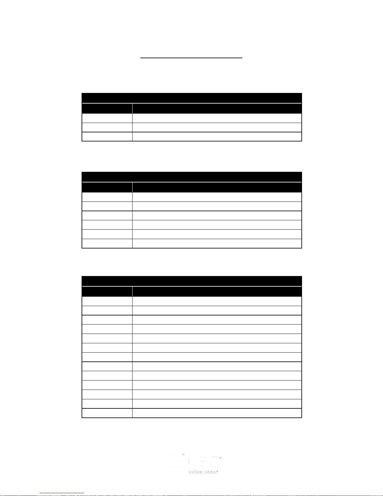
LPX AUTOMATED SEED TREATER
LPX AUTOMATED TREATER
TABLE 1
Part # Description
01-01-0105 MOTOR ATOMIZER .33 HP 230V
01-01-0105 MOTOR ATOMIZER .33 HP 460V
01-01-0144 MOTOR ATOMIZER .50 HP 575V
TABLE 2
Part # Description
01-01-0106 MOTOR DRUM 1.5 HP 230V
01-01-0106 MOTOR DRUM 1.5 HP 460V
01-01-0146 MOTOR DRUM 1.5 HP 575V
01-01-0166 MOTOR DRUM 3.0 HP 230V
01-01-0166 MOTOR DRUM 3.0 HP 460V
TBD MOTOR DRUM 3.0 HP 575V
Page 96
TABLE 3 (6 and 8 foot drums)
Part # Description
03-12-0168 PNL CNTL LPX TRTR 230V 1PH 5HP
03-12-0169 PNL CNTL LPX TRTR 230V 3PH 5HP
03-12-0202 PNL CNTL LPX TRTR 230V 3PH 5/7.5HP
03-12-0203 PNL CNTL LPX TRTR 230V 3PH 7.5/5HP
03-12-0204 PNL CNTL LPX TRTR 230V 3PH 7.5HP
03-12-0170 PNL CNTL LPX TRTR 460V 3PH 5HP
03-12-0205 PNL CNTL LPX TRTR 460V 3PH 5/7.5HP
03-12-0206 PNL CNTL LPX TRTR 460V 3PH 7.5/5HP
03-12-0207 PNL CNTL LPX TRTR 460V 3PH 7.5HP
03-12-0171 PNL CNTL LPX TRTR 575V 3PH 5HP
03-12-0208 PNL CNTL LPX TRTR 575V 3PH 5/7.5HP
03-12-0209 PNL CNTL LPX TRTR 575V 3PH 7.5/5HP
03-12-0210 PNL CNTL LPX TRTR 575V 3PH 7.5HP
Page 97

LPX AUTOMATED SEED TREATER
LPX AUTOMATED TREATER
TABLE 4 (10 foot drums)
Part # Description
03-12-0240 PNL CNTL LPX TRTR 230V 1PH 5HP/3HP DRUM MTR
03-12-0241 PNL CNTL LPX TRTR 230V 3PH 5HP/3HP DRUM MTR
03-12-0242 PNL CNTL LPX TRTR 230V 3PH 5/7.5HP/3HP DRUM MTR
03-12-0243 PNL CNTL LPX TRTR 230V 3PH 7.5/5HP/3HP DRUM MTR
03-12-0244 PNL CNTL LPX TRTR 230V 3PH 7.5HP/3HP DRUM MTR
03-12-0239 PNL CNTL LPX TRTR 460V 3PH 5HP/3HP DRUM MTR
03-12-0238 PNL CNTL LPX TRTR 460V 3PH 5/7.5HP/3HP DRUM MTR
03-12-0237 PNL CNTL LPX TRTR 460V 3PH 7.5/5HP/3HP DRUM MTR
03-12-0236 PNL CNTL LPX TRTR 460V 3PH 7.5HP/3HP DRUM MTR
03-12-0245 PNL CNTL LPX TRTR 575V 3PH 5HP/3HP DRUM MTR
03-12-0246 PNL CNTL LPX TRTR 575V 3PH 5/7.5HP/3HP DRUM MTR
03-12-0247 PNL CNTL LPX TRTR 575V 3PH 7.5/5HP/3HP DRUM MTR
03-12-0248 PNL CNTL LPX TRTR 575V 3PH 7.5HP/3HP DRUM MTR
TABLE 5
Part # Description
13-04-0043 INLET EXTENSION CHUTE - 12 INCH
13-04-0121 INLET EXTENSION CHUTE - 6 INCH
Page 97
Page 98
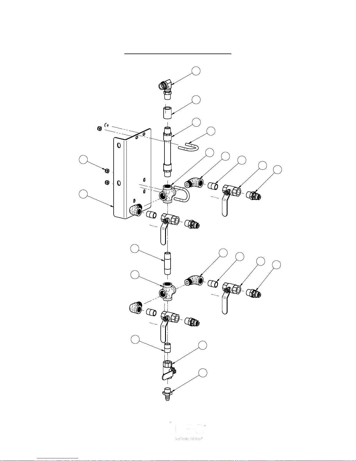
Item # Part # Rev Title Qty
1 02-02-0006 A VLV BALL .500 NPT 2WAY BRSS 5
2 02-05-0005 A COUPLER, .500-14 FEMALE,SS 150PSI 1
3 02-06-0020 A FTTG 90 DEG STRT .500NPTX .500NPT 4
4 02-07-0007 A FTTG NIP .500 NPT X 1.125 TBE SS 1
5 02-07-0007 A FTTG NIP .500 NPT X 1.125 TBE SS 4
6 02-07-0019 A NIPPLE, .500-14 NPT X 3.0 LG 304SS 1
7 02-08-0007 A FTTG STGHT .500HB X .500NPT ML NYL 1
8 02-11-0001 A FTTG CROSS .500 NPT FM SS 2
9 02-15-0014 A FTTG CPLG .500 NPT QCK DISC INSERT 4
10 02-16-0050 A FTTG PUSH 90DEG .625ODX.500 NPT ML 1
11 04-03-0030 A MXR IL PVC 6ELEMENT .500PIPE X 7.00 1
12 05-10-2891B B STATIC MIXER & MNFLD MNT BRKT 1
13 06-01-0037 A BOLT U .313-18 X 1.38 X 2.188 ZP 2
14 06-03-0002 A NUT NYL LOCK .313-18 ZP GR5 4
10
2
11
13
14
12
3
5
1
9
6
8
3
5
1
9
4
1
7
8
LPX AUTOMATED SEED TREATER
LPX STATIC MIXER (04-03-0157)
Page 98
Page 99

LPX AUTOMATED SEED TREATER
LPX STATIC MIXER (04-03-0157)
Item # Part #
1 02-02-0006
VLV BALL .500 NPT 2WAY BRSS 5
Description Qty
2 02-05-0005 COUPLER, .500-14 FEMALE,SS 150PSI 1
3 02-06-0020 FTTG 90 DEG STRT .500NPTX .500NPT 4
4 02-07-0007 FTTG NIP .500 NPT X 1.125 TBE SS 1
5 02-07-0007 FTTG NIP .500 NPT X 1.125 TBE SS 4
6 02-07-0019 NIPPLE, .500-14 NPT X 3.0 LG 304SS 1
7 02-08-0007 FTTG STGHT .500HB X .500NPT ML NYL 1
8 02-11-0001 FTTG CROSS .500 NPT FM SS 2
9 02-15-0014 FTTG CPLG .500 NPT QCK DISC INSERT 4
10 02-16-0050 FTTG PUSH 90DEG .625ODX.500 NPT ML 1
11 04-03-0030 MXR IL PVC 6ELEMENT .500PIPE X 7.00 1
12 05-10-2891B STATIC MIXER & MNFLD MNT BRKT 1
13 06-01-0037 BOLT U .313-18 X 1.38 X 2.188 ZP 2
14 06-03-0002 NUT NYL LOCK .313-18 ZP GR5 4
Page 99
Page 100
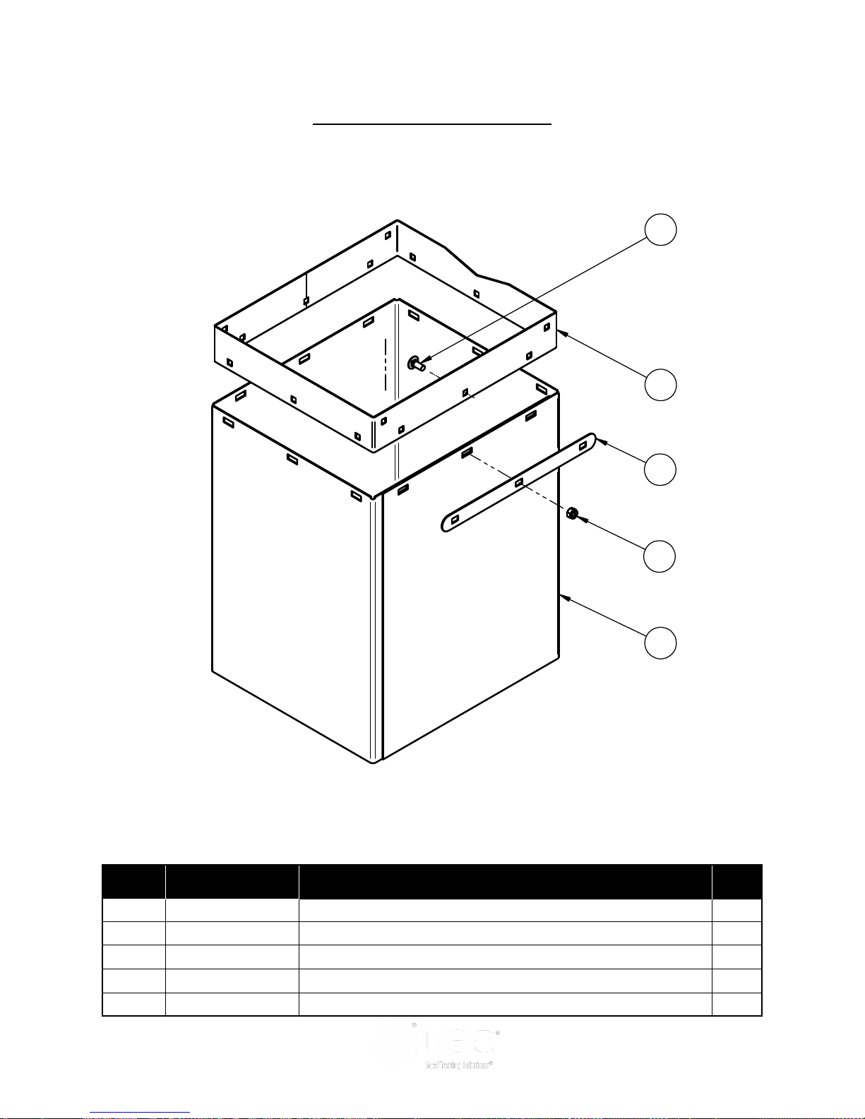
LPX AUTOMATED SEED TREATER
2
3
1
5
4
LPX END CHUTE (18-01-0072)
Item # Part #
1 05-10-3400
2 05-10-3886 SKIRT DSCHG TRTR LPX2000 1
3 06-01-0171 BOLT CRG .3125-18X.750 ZP SHORT NECK 12
4 06-03-0002 NUT NYL LOCK .313-18 ZP GR5 12
5 101FB5 ADPT END CHUTE EXT LPX2000 1
Page 100
PLT DSCHG TRTR 4
Description Qty
 Loading...