

Page 1

LPV PORTABLE SEED TREATER
Operators Manual
Document: TD-09-06-1052 Revision: A
2320 124th Road Sabetha, Kansas 66534 PH: (785) 431-7900 FAX: (785) 431-7950 www.uscllc.com
Revision Effective 28 MAR 2018
Page 2

PORTABLE LPV TREATER
Introduction
Thank you for choosing USC, LLC for your equipment needs. We appreciate your
business and will work diligently to ensure that you are satisfied with your choice.
OVERVIEW
The purpose of this manual is to provide you with the basic information needed to
operate and maintain the LPV Portable Treater It does not hold USC, LLC liable
for any accidents or injuries that may occur.
The technical information provided in this document is based on extensive testing
under controlled conditions at the USC research and development facility.
This information is given without guarantee as the conditions of operation and storage
of the equipment are beyond our control. Variables such as temperature, humidity,
viscosity of chemical products and changes in seed size or variety may all effect
the accuracy of application and seed coverage. Periodically check the equipment
calibration while treating and make adjustments as required. This will insure the
optimum seed coverage.
OPERATOR RESPONSIBILITIES
As the purchaser/owner/operator of this equipment and control system, you have an
obligation to install, operate, and maintain the equipment in a manner that minimizes
the exposure of people in your care to any potential hazards inherent in using this
equipment. It is critical that the owner of this equipment:
Has a clear and documented understanding of the process this machine is
being used in and of any resulting hazards or special requirements arising
from this specific application.
Allow only properly trained and instructed personnel to install, operate or
service this equipment.
Maintain a comprehensive safety program involving all who work with this
machine and other associated process equipment.
Establish clear areas of staff responsibility (e.g. operation, setup, sanitation,
maintenance, and repairs).
Provide all personnel with necessary safety equipment.
Periodically inspect the equipment to insure that the doors, covers, guards,
and safety devices are in place and functioning, that all safety instructions
and warning labels are intact and legible, and that the equipment is in good
working order.
In addition to the operating instructions, observe and enforce the applicable
legal and other binding regulations, national and local codes.
Page 2
Page 3

PORTABLE LPV TREATER
As the person with the most to gain or lose from working safely, it is important that you
work responsibly and stay alert. By following a few simple rules, you can prevent an
accident that could injure or kill you or a co-worker.
Disconnect, lockout, and tagout electrical and all other energy sources
before inspecting, cleaning, servicing, repairing, or any other activity that
would expose you to the hazards of electrical shock.
Do not operate, clean, or service this equipment until you have read and
understood the contents of this manual. If you do not understand the
information in this manual, bring it to the attention of your supervisor, or call
USC at (785) 431-7900 for assistance.
Any operator who is known or suspected to be under the influence of alcohol
or drugs should not be allowed to operate the equipment.
Understand and follow the safety practices required by your employer and
this manual.
PAY ATTENTION to what you and other personnel are doing and how these
activities may affect your safety.
Failure to follow these instructions may result in serious personal
injury or death.
RECEIVING YOUR EQUIPMENT
As soon as the equipment is received, it should be carefully inspected to make certain
that it has sustained no damage during shipment and that all items listed on the
packing list are accounted for. If there is any damage or shortages, the purchaser
must immediately notify USC, LLC. Ownership passes to purchaser when the unit
leaves the USC, LLC. premises. The purchaser is responsible for unloading and
mounting all components of the equipment.
Document the serial number of the conveyors for future reference. The serialization
labels are located on the right side of each conveyor near the inlet end.
INLET CONVEYOR SERIAL NUMBER:_____________________________________
OUTLET CONVEYOR SERIAL NUMBER:___________________________________
Page 3
Page 4

PORTABLE LPV TREATER
Document the vehicle identification number for future reference. On gooseneck
trailers, the V.I.N. is located on a sticker on the side near the top of the gooseneck as
shown below.
V.I.N.
Number
TRAILER V.I.N. NUMBER:_______________________________________________
Document the vehicle identification number for future reference. On bumper hitch
trailers, the V.I.N. is located on the side of the deck, in the left front corner.
V.I.N.
Number
TRAILER V.I.N. NUMBER:_______________________________________________
Page 4
Page 5

PORTABLE LPV TREATER
Table of Contents
Section Contents Page #
Section A Safety Instructions ..................................................................... 6
Section B Installation ................................................................................ 15
Section C Mechanical Operation .............................................................. 17
Fill Hopper, Inlet Conveyor ..................................................... 18
Outlet Conveyor Hydraulics ..................................................... 18
Outlet Conveyor ...................................................................... 18
Portable Treater Overview ...................................................... 19
Section D Electrical Operation ................................................................. 21
Treater Setup .......................................................................... 22
Preparing Treater for Transport ............................................... 27
Section E Troubleshooting ....................................................................... 28
Unplugging ............................................................................. 29
Section F Maintenance ............................................................................. 30
Section G Belt Tensioning Specification ................................................. 35
Section H Storage ...................................................................................... 36
Section I Mechanical Drawings ............................................................... 38
Section J Limited Warranty ...................................................................... 87
Page 5
Page 6
PORTABLE LPV TREATER
Section
A
Every year accidents in the work place maim, kill and injure people. Although it may
be impossible to prevent all accidents, with the right combination of training, operating
practices, safety devices, and operator vigilance, the number of accidents can be
significantly reduced. The purpose of this section is to educate equipment users
about hazards, unsafe practices, and recommended hazard avoidance techniques.
It is very important that operators and maintenance personnel understand the words
and symbols that are used to communicate safety information. Safety words, their
meaning and format, have been standardized for U.S. manufacturers and published
by the American National Standards Institute (ANSI). The European Community (E.C.)
has adopted a different format based on the International Standards Organization
(I.S.O.) and applicable machinery directives. Both formats are presented below.
Graphic symbols are not standardized, but most manufacturers will use some variation
of the ones seen in this manual.
Safety Instructions
SAFETY WORDS AND SYMBOLS
SAFETY
INSTRUCTIONS
Indicates an imminently hazardous situation which, if not
avoided, will result in death or serious injury.
Indicates a potentially hazardous situation which, if not avoided,
could result in death or serious injury.
Indicates a potentially hazardous situation which, if not avoided,
may result in minor or moderate injury and/or property damage.
Provides additional information that the operator needs to be
aware of to avoid a potentially hazardous situation.
The minimum clearance height requirement for the LPV
Portable Treater is the same as a standard semi trailer,
13 FEET 6 INCHES.
Page 6
Page 7

PORTABLE LPV TREATER
Mandatory Lockout Power Symbol. Disconnect, lockout and
tagout electrical and other energy sources before inspecting,
cleaning or performing maintenance on this panel.
International Safety Alert Symbol. The exclamation point (!)
surrounded by a yellow triangle indicates that an injury hazard
exists. However, it does not indicate the seriousness of potential
injury. The exclamation point (!) is also used with the DANGER,
WARNING and CAUTION symbols so the potential injury is
indicated.
Electrocution Hazard Symbol. This symbol indicates that an
electrocution hazard exists. Serious injury or death could result
from contacting high voltage.
NOTICE
International Electrocution Hazard. This symbol indicates that
an electrocution hazard exists. Serious injury or death could result
from contacting high voltage.
Mandatory Read Manual Action Symbol. (I.S.O. format) This
symbol instructs personnel to read the Operators Manual before
servicing or operating the equipment.
Mandatory Read Manual Action Symbol. This symbol
instructs personnel to read the Operators Manual before
servicing or operating the equipment.
Notice is used to notify people of important installation, operation
or maintenance information which is not hazard related.
Page 7
Page 8

PORTABLE LPV TREATER
LOCKOUT / TAGOUT PROCEDURES
Lockout/Tagout is the placement of a lock/tag on an energy isolating device in
accordance with an established procedure. When taking equipment out of service to
perform maintenance or repair work, always follow the lockout/tagout procedures as
outlined in ANSI Z344.1 and/or OSHA Standard 1910.147. This standard “requires
employers to establish a program and utilize procedures for affixing appropriate
lockout devices or tagout devices to energy isolating devices and to otherwise disable
machines or equipment to prevent unexpected energizing, start-up, or release of
stored energy in order to prevent injury to employees.”
EMERGENCY STOP
There are three Emergency Stop push buttons on the Portable LPV
Seed Treater. One is located on the I / O control panel mounted on
the side of the treater, and one each on the Treater Control and Main
Control Panels mounted on the side of the trailer. All Actuators of
emergency stop shall be colored RED. The background immediately
around the device actuator shall be colored YELLOW. The actuator
pushbutton operated device shall be of the palm or mushroom
head type.
If the treater is equipped with the optional portable generator,
there is also an emergency stop on the generator that would
NOTICE
shut down the power source. This is not the preferred method
for emergency shutdown.
CONTROLLED STOP
This is the stopping of machine motion by reducing the electrical command signal to
0 (zero) once the stop signal has been recognized. The operator initiates this stop by
pressing the PAUSE button at he bottom of the main screen.
HAZARD REVIEW
Electrocution Hazard
Electrocution accidents are most likely to occur during
maintenance of the electrical system or when working on or near
exposed high voltage wiring. This hazard does not exist when the
electrical power has been disconnected, properly locked, and
tagged out.
Automatic Start Hazard
This equipment may be controlled by an automated system and
may start without warning. Failure to properly disconnect, lockout,
and tagout all energy sources of remotely controlled equipment
creates a very hazardous situation and could cause injury or
even death. PLEASE STAY CLEAR AND BE ALERT.
Page 8
Page 9

PORTABLE LPV TREATER
YOU are responsible for the SAFE operation and maintenance of your USC, LLC
equipment . YOU must ensure that you and anyone else who is going to operate,
maintain or work around the equipment be familiar with the operating and maintenance
procedures and related SAFETY information contained in this manual. This manual will
take you step-by-step through your working day and alert you to good safety practices
that should be adhered to while operating the equipment
Remember, YOU are the key to safety. Good safety practices not only protect you,
but also the people around you. Make these practices a working part of your safety
program. Be certain that EVERYONE operating this equipment is familiar with the
recommended operating and maintenance procedures and follows all the safety
precautions. Most accidents can be prevented. Do not risk injury or death by ignoring
good safety practices.
Equipment owners must give operating instructions to operators or employees
before allowing them to operate the machine, and at least annually thereafter
per OSHA (Occupational Safety and Health Administration) regulation 1928.57.
The most important safety device on this equipment is a SAFE operator. It is the
operator’s responsibility to read and understand ALL Safety and Operating
instructions in the manual and to follow them. All accidents can be avoided.
A person who has not read and understood all operating and safety instructions is
not qualified to operate the machine. An untrained operator exposes himself and
bystanders to possible serious injury or death.
Do not modify the equipment in any way. Unauthorized modification may impair the
function and/or safety and could affect the life of the equipment.
Think SAFETY! Work SAFELY!
GENERAL SAFETY
1. Read and understand the operator’s manual and all safety labels
before operating, maintaining, adjusting or unplugging the
equipment .
2. Only trained persons shall operate the equipment . An untrained
operator is not qualified to operate the machine.
3. Have a first-aid kit available for use should the need arise,
and know how to use it.
Page 9
Page 10

PORTABLE LPV TREATER
4. Provide a fire extinguisher for use in case of an accident. Store in
a highly visible place.
5. Do not allow children, spectators or bystanders within hazard area
of machine.
6. Wear appropriate protective gear. This includes but is not limited
to:
A hard hat
Protective shoes with slip resistant soles
Protective goggles
Heavy gloves
Hearing protection
Respirator or filter mask
7. Place all controls in neutral or off, stop motor, and wait for all
moving parts to stop. Then disable power source before servicing,
adjusting, repairing, or unplugging.
8. Review safety related items annually with all personnel who will be
operating or maintaining the equipment.
OPERATING SAFETY:
1. Read and understand the operator’s manual and all safety labels before using.
2. Disconnect and disable electrical supply completely and wait for all moving parts to
stop before servicing, adjusting, repairing or unplugging.
3. Clear the area of bystanders, especially children, before starting.
4. Be familiar with the machine hazard area. If anyone enters hazard area, shut down
machine immediately. Clear the area before restarting.
5. Keep hands, feet, hair and clothing away from all moving and/or rotating parts.
6. Stay away from overhead obstructions and power lines during operation and
transporting. Electrocution can occur without direct contact.
7. Do not operate machine when any guards are removed.
8. Inspect welds and repair if needed.
Page 10
Page 11

PORTABLE LPV TREATER
PLACEMENT SAFETY
1. Move only with the appropriate equipment.
2. Ensure there is enough clearance from overhead obstructions and other equipment
to move the machine into its working position. 13 feet 6 inches is required to clear
the top of the inlet conveyor.
3. Stay away from overhead power lines when moving equipment. Electrocution can
occur without direct contact.
4. Operate the equipment on level ground free of debris. USC strongly
recommends that the trailers is attached to the tow vehicle whenever the
discharge conveyor is deployed and the treating system is in use.
MAINTENANCE SAFETY
1. Review the operator’s manual and all safety items before
working with, maintaining or operating the equipment .
2. Place all controls in neutral or off, stop motors, disable power
source, and wait for all moving parts to stop before servicing,
adjusting, repairing or unplugging.
3. Follow good shop practices:
Keep service area clean and dry.
Be sure electrical outlets and tools are properly grounded.
Use adequate light for the job at hand.
4. Keep hands, feet, hair and clothing away from all moving and/or rotating parts.
5. Clear the area of bystanders, especially children, when carrying out any
maintenance and repairs or making any adjustments.
6. Before resuming work, install and secure all guards when maintenance work is
completed.
Page 11
Page 12

PORTABLE LPV TREATER
SAFETY LABELS
1. Keep safety labels clean and legible at all times.
2. Replace safety labels that are missing or have become illegible.
3. Replaced parts that displayed a safety label should also display the current label.
4. Replacement safety labels are available. Contact USC at (785) 431-7900 .
How to Install Safety Labels:
Be sure that the installation area is clean and dry.
Be sure temperature is above 50
Decide on the exact position before you remove the backing paper.
Remove the smallest portion of the split backing paper.
Align the sign over the specified area and carefully press the small portion with
o
F (10oC).
the exposed sticky backing in place.
Slowly peel back the remaining paper and carefully smooth the remaining
portion of the sign in place.
Small air pockets can be pierced with a pin and smoothed out using the piece
of sign backing paper.
Located on the USC equipment you will find safety labels.
Always be sure to read and follow all directions on the labels.
Page 12
Guards provided with USC equipment are to remain in place
during operation.
Page 13

PORTABLE LPV TREATER
Think SAFETY! Work SAFELY!
REMEMBER—If safety labels have been damaged, removed, become illegible, or
parts replaced without safety labels, new labels must be applied. New safety labels are
available from USC at (785) 431-7900.
Part # 09-02-0010
Part # 09-02-0003
Part # 09-02-0015
Part # 09-02-0001
Part # 09-02-0002
Page 13
Page 14

PORTABLE LPV TREATER
Part # 09-02-0007 Part # 09-02-0006
Page 14
Part # 09-02-0011
Part # 09-02-0009
Part # 09-02-0012
Page 15
PORTABLE LPV TREATER
Section
Installation
HIGH VOLTAGE ~ Always disconnect the power source
before working on or near the control panel or lead wires.
HIGH VOLTAGE ~ Use insulated tools when making
adjustments while the controls are under power.
B
1. If the treater does not come equipped with a generator, or you are
supplying your own generator, have a certified electrician provide
power to the seed treating system. The treater panel is the only
equipment that is hard wired (below). This will power the USC
LPV Seed treater and any attached conveyors. All other
equipment requires a properly grounded 110V source. Provide
convenient shutdown switches, comply with local electrical codes
and ensure that the system is properly grounded and bonded.
All USC control panels must be connected adhering to the same
electrical requirements as specified in the main control panel on
the power requirement tag (right), or the electrical schematic
shipped with the piece of equipment.
NOTICE
A minimum rating of 34 KW is required when using
a generator with the system.
Incoming power connected to
these terminals in the Treater
Control Panel
Page 15
Page 16

PORTABLE LPV TREATER
INSTALLATION
2. Remove any boxes from the drum of the treater.
3. Inspect machine thoroughly for screws, bolts, fittings, etc. which may have come
loose during shipping.
4. If not using a generator, disconnect power before moving the treater to another
location.
When using a generator as a power source,
USC recommends grounding the treating system
according to local electrical codes. Two ground lugs
are provided on the trailer. One at the left front corner
and one on the right rear corner of the trailer.
Page 16
Page 17
PORTABLE LPV TREATER
Mechanical Operation
Section
C
The Tube Series Conveyor is designed to efficiently move seed between a storage
facility or seed totes and a truck, trailer or seed treater. Power is provided by an
electric motor. Be familiar with the machine before starting.
It is the responsibility of the owner or operator to read this manual and to train all
other operators before they start working with the machine. In addition to the design
and configuration of equipment, hazard control and accident prevention are dependent
upon the awareness, concern, and prudence of personnel involved in the operation,
transport, maintenance and storage of equipment or in the use and maintenance of
facilities.
NOTICE
Many features incorporated into this machine are the result of suggestions made by
customers like you. Read this manual carefully to learn how to operate the machine
safely and how to set it to provide maximum efficiency. By following the operating
instructions in conjunction with a good maintenance program, your conveyor will
provide many years of trouble free service.
Follow all safety instructions exactly. Safety is everyone’s business.
By following recommended procedures, a safe working environment
is provided for the operator, bystanders and the area around the
worksite. Untrained operators are not qualified to operate the
machine.
Page 17
Page 18

PORTABLE LPV TREATER
PORTABLE LPV TREATER OVERVIEW
FILL HOPPER
The fill hopper holds 65 units of seed. The hopper feeds into the inlet conveyor using
a rack and pinion gate.
INLET CONVEYOR
The 17 foot inlet conveyor feeds into the seed treater supply hopper. The conveyor
plugs into a receptacle on the bottom of the treater control panel marked (Inlet
Conveyor). The inlet conveyor is tied in with a proximity switch located in the 8 inch
hopper extension ring. When seed reaches up and covers the proximity switch, the
inlet conveyor will automatically shut-off so the hopper will not overflow. The conveyor
will remain off until seed drops below the proximity switch. When the proximity sensor
no longer detects seed, a timer relay will begin to count down to a pre-set time and turn
the conveyor back on. The time delay prevents the conveyor from turning on and off
too quickly.
NOTICE
If the inlet conveyor will not turn on after being shut down
awhile, this may mean the proximity switch is malfunctioning.
Refer to the Proximity Switch Adjustment Guide in the U-Treat
manual.
OUTLET CONVEYOR HYDRAULICS
The outlet conveyor is stored for transportation parallel to the trailer. An electric
powered motor drives the hydraulic system that deploys the conveyor to an operating
position, and then returns it to the transporting position after the treating process is
complete. The conveyor must always be at a full 90 degrees from the trailer when
in use.
OUTLET CONVEYOR
As seed passes through the length of the treater drum, it is tumbled, producing
accurate and uniform seed coating. The seed then exits the seed treater out the
discharge chute of the machine and into the 20 foot outlet conveyor. The conveyor
plugs into a receptacle on the bottom of the treater control panel marked (Outlet
Conveyor). The seed is then discharged into a pro box, trailer, or any other container.
Page 18
Never allow exposure of persons or clothing to the drive shaft,
idler wheels, or the treater drum during operation. Always have
the safety shields in place during operation.
Page 19

PORTABLE LPV TREATER
PORTABLE LPV TREATER OVERVIEW
Hopper
Supply
Wheel
Metering
Seed
Inlet
Conveyor
Stand
Pump
Stairs
Movable
Pump Motor
Hydraulic
Controls
Hydraulic
Trailer
Gooseneck
Treater
Seed
LPV
Feeder
Additive
Dry
Page 19
Page 20

PORTABLE LPV TREATER
PORTABLE LPV TREATER OVERVIEW
Conveyor
Outlet
40 kW
Generator
Page 20
Outlet Conveyor
Box
Distribution
Power
Panel
Control
Treater
Panel
Main Control
Automated
Handle
Lock Down
Page 21
PORTABLE LPV TREATER
Section
Electrical Operation
HIGH VOLTAGE ~ Always disconnect the power source
before working on or near the control panel or lead wires.
HIGH VOLTAGE ~ Use insulated tools when making
adjustments while the controls are under power.
AUTHORIZED PERSONNEL only shall work on the control
panel. Never allow anyone who has not read and familiarized
themselves with the owner’s manual to open or work on the
control panel.
This section provides a general overview and description of the operator controls for
the Portable LPV Treater.
NOTICE
General Panel Descriptions:
USC recommends the use of a surge protection device with a
minimum rating of 400 Joules for all automated main control
panels.
D
All three panels are located side by side on the right side of the trailer at the center.
The U-Connect-Pro Control Panel is an enclosure that contains the HP T620 Thin
Client. This device converts the user supplied internet signal and sends it to the
main control panel. Power to this panel is supplied from a power cable to a
standard 115V outlet.
The LPV Treater Control Panel is an enclosure that contains the electrical
components required to actuate the seed treater. This includes the VFDs
for the seed wheel and atomizer. Power for the treater is supplied here.
Power to this panel is hard wired.
The Automated Main Control Panel is a plug connected enclosure. It contains
the PLC (Programmable Logic Controller) as well as the HMI (Human Machine
Interface) touch screen. The operator is able to control the entire system through
the HMI. Power to this panel is supplied from a power cable to a standard 115V
outlet.
Page 21
Page 22

PORTABLE LPV TREATER
For the LPV Automated Treater HMI Touch screens, see the appropriate U-Treat
Automation manual.
TREATER SET UP
USC strongly recommends that the trailers is attached
to the tow vehicle whenever the discharge conveyor is
deployed and the treating system is in use.
The following steps outline the set-up of your USC Portable LPV Treater :
1. Clear the area of bystanders, especially small children, before moving.
2. Attach the Portable System to an appropriate towing vehicle.
3. Ensure there is enough clearance from overhead obstructions and power lines
or other equipment to move the machine into its working position. 13 feet 6 inches
is required to clear the top of the inlet conveyor.
4. Move the portable system to a desired position on a level surface ensuring the
machine remains stable during the treating process.
5. Set the park brake on the towing vehicle before dismounting.
6. Lower the trailer jacks to provide additional stability during the treating process.
If you are going to operate without the tow vehicle attached, the trailer may not
be more than 5 degrees low on the discharge conveyor side. With the vehicle
attached the angle may be no more than 10 degrees. Use the trailer jacks
to make the trailer as level as possible. If the angle is too steep, the equipment
may topple or work improperly, damaging the equipment and or causing
personal injury.
7. Remove the Clevis pins
from both sides of the
portable steps (left), and
rotate them into the working
position (right). Insert both
pins back into the mounting
bracket to avoid misplacing
them.
Page 22
Page 23
PORTABLE LPV TREATER
GENERATOR OPERATION
8. If using a fixed power source, provide power using the instructions on page 15.
If using the USC provided generator, follow steps one through four to operate the
generator. Before you start the generator, ensure that all switches on the treater,
pumps stands, hydraulic motor and control panels as well as the main disconnect
switch on the generator are in the OFF position.
3
1
STEP 1 - Turn On Panel Display: Move the control
panel power switch up into the ON position.
The display will turn on and the red LED on the start
switch will begin to flash on and off. The icon in the
lower right corner indicates what mode of manual
operation the generator is in. See table below.
2
Main Power
Disconnect
Switch
Page 23
Page 24

PORTABLE LPV TREATER
GENERATOR OPERATION
8. (Continued).
STEP 2: Start Generator. Press the green Start
button on the generator. There will be a short pause
for system checks, then generator will begin cranking
over to start. Once the generator is running,
the display will show the voltage ramping up from
0 to 120 volts and an hour glass will appear in the
lower right corner of the screen untill both voltages
read 120v.
If the generator fails to start after cranking for ten seconds,
it will pause for ten seconds and then begin cranking
a second time. If it fails to start after three attempts it will
NOTICE
stop and display an error message. Example: Low Fuel Level
or Battery Under Voltage. Once the problem is resolved,
press the Start button again.
When L1N and L2N have reached 120v the hour glass
will turn into a motor piston moving up and down.
The generator is ready for use. Move the main power
disconnect switch to the right into the ON position.
Power is now available to the control panels,
spider box and hydraulic motor power switch.
STEP 3: Shutdown Generator. When you are done treating, turn off the treater
panel, main control panel, pump stand mix motors and hydraulic motor. Move the
main disconnect switch to the left placing it in the OFF position. Shutdown the
generator by pressing the red Stop button. The hour glass will come back and after
the preset time elapses it will gradually reduce speed until it shutsdown. After it has
stopped running, move the control panel power switch down to the OFF position.
If left on it will drain the generator battery.
For an operators manual with more detailed information regarding the display functions
go to the Deep Sea Electronics website and download document number 057-260 at:
https://www.deepseaplc.com/genset/manual-auto-start-control-modules/dse4510
Page 24
Page 25

PORTABLE LPV TREATER
TREATER SET UP
9. Now that the generator is up and running, Turn on the power to the treater, treater
I / O and Main Control Panels.
10. Use the following steps to deploy the discharge conveyor.
STEP 1: Remove the hitch pin from the treater drum
transport bracket located next to the drum actuator.
Hitch
Pin
STEP 2: Go to the main control panel HMI treater
main screen. Press the HOA button. Press and hold
the UP button on the drum actuator module and raise
the drum until the inside drum frame is level with or
above the outside treater frame.
STEP 3: Remove the hitch pin from the outlet conveyor lockdown handle (bottom, left).
Hold the latch rod in one hand and lift the handle with the other hand until the latch
crossbar clears the conveyor lock on the conveyor head. Allow the latch rod to rest
at the bottom of the slot on the supprt plate (bottom, right). The conveyor is now ready
to move to a working position.
Hitch
Pin
Page 25
Page 26

PORTABLE LPV TREATER
TREATER SET UP
STEP 4: Press the black start button on the hydraulic
motor power switch.
STEP 5: Use the left control lever to raise the
outlet conveyor until it is out of the cradle.
STEP 6: Use the right control lever to rotate the
outlet conveyor out until it reaches the dead
stop, a full 90 degrees from the trailer.
STEP 7: Use the left control lever to raise the
outlet conveyor until it is high enough to clear
the receptacle you will be discharging the
treated seed into.
After the outlet conveyor has been moved into a working position,
NOTICE
you may turn off the hydraulic motor. It is only necessary for it to
be running when moving the conveyor.
Page 26
Page 27

PORTABLE LPV TREATER
PREPARING TREATER FOR TRANSPORT
1. Run the system untill all of the seed is out of the treater and the outlet conveyor.
2. Go to the main control panel HMI treater main screen. Press the HOA button.
Press and hold the UP button on the drum actuator module and raise the drum
until the inide drum frame is level with or above the outside treater frame.
3. Use the right control lever to rotate the outlet conveyor in until it reaches the dead
stop and is now parallel with the trailer.
4. Use the left control lever to lower the outlet conveyor until it is resting inside of the
cradle.
5. Turn off the hydraulic motor.
6. Secure the outlet conveyor by following step three of the treater set up procedure
on page 25 in reverse.
7. Go to the main control panel HMI treater main screen. Press and hold the DOWN
button on the drum actuator module and lower the drum until it stops, then insert
the clevis pin back in the drum transport bracket.
8. Turn off the pump stand motors that are still running.
9. Turn off the power to the treater and Main Control Panels.
10. After all systems have been turned off, shutdown the generator by placing the main
disconnect switch in the OFF position. Then press the red button once to shutdown
the generator.
Page 27
Page 28

PORTABLE LPV TREATER
Section
E
Below is a table describing the most frequent problems and solutions with the Inlet and
Outlet conveyors. For further assistance, contact the USC Service department at
(785) 431-7900.
Troubleshooting
TROUBLESHOOTING
Problem Possible Cause Solution
Conveyor will not run. 1. Not turned on.
2. Conveying belt loose.
3. Drive belt loose.
Belt edge fraying. 1. Belt not aligned. 1. Align and tension belt.
Low conveying capacity. 1. Angle too steep.
2. Slow operating speed.
3. Conveyor belt slipping.
4. Drive belt slipping.
Discharge conveyor will not
rotate right, left or raise up and
down.
1. Hydraulic line is leaking.
2. Not enough fluid in system.
3. Object is obstructing travel.
1. Start power source or turn on
power.
2. Tighten and align belt.
3. Tighten drive belt.
1. Reposition with angle at 30o.
2. Increase operating speed.
3. Tighten belt.
4. Set drive belt tension.
1. Repair or replace hose.
2. Check fluid level in
reservoir. Add fluid.
3. Remove obstruction.
Treater E-Stops. Alarm message
reads: “Drum Tilt Actuator NOT
in requested position”.
Page 28
1. Treater is positioned at an
angle that is to steep
because the trailer is not on
level ground. The front or the
back are too low.
2. Trailer can not be leveled at
the current location
1. Level the trailer, then reset
the system and continue to
treat.
2. The treater inclinometer is
based on true line of gravity.
If the trailer can not be
leveled. Log into the system
as ADMIN and go to page 3
of the setpoints. Open up
the angle tolerance. Plus or
minus ten degrees is the
maximum allowed. Refer to
the U-Treat manual for more
information.
Page 29
PORTABLE LPV TREATER
UNPLUGGING
In unusual moisture or material conditions, the machine can plug. When unplugging,
follow this procedure:
1. Place all controls in neutral or off, stop motor, disable and lock out power source
before unplugging.
2. Remove the nut, bolt and sliding clean out door from the bottom of the inlet tube
section of the conveyor. Remove any built up material. Reinstall door and
hardware.
Clean
Out
Doors
3. Open the tail cover (below).
4. Remove plugged material.
5. Install and secure conveyor and tail covers.
Remove shipping bolts
after receiving
conveyor
Bottom clean-out cover
Bottom clean-out cover removed
Page 29
Page 30

PORTABLE LPV TREATER
Section
F
Proper maintenance of the Portable LPV Treater is critical for peak performance,
reliability and accuracy of this system. The following is a guideline for the type of
maintenance and servicing that should be performed on this unit. Your environment
and uses may require additional maintenance and service beyond this list to assure
a reliable and safe unit. The operator of this unit has ultimate responsibility to identify
areas of concern and rectify them before they become a hazard or safety issue.
There is no substitute for a trained, alert operator.
If the portable treater is equipped with a Husker Power generator, refer to the
Isuzu Diesel operators manual shipped in a box with all the other documentation.
Maintenance
Do not put this unit into operation with any questionably
maintained parts. Poor performance or a hazard may occur.
ELECTRIC GENERATOR
FLUIDS AND LUBRICANTS
Grease
Use an SAE multipurpose high temperature grease with extreme pressure (EP)
performance. Also acceptable is an SAE multipurpose lithium-based grease.
Hydraulic Oil
Use DTE 25 hydraulic oil for Electric Powered Hydraulic Pack.
Storing Lubricants
Your machine can operate at top efficiency only if clean lubricants are used. Use clean
containers to handle all lubricants. Store them in an area protected from dust, moisture
and other contaminants.
GREASING
Use a Maintenance Checklist to keep record of all scheduled maintenance.
Use a hand-held grease gun for all greasing.
Wipe grease fitting with a clean cloth before greasing to avoid injecting dirt and grit.
Replace and repair broken fittings immediately.
NOTICE
Page 30
If fittings will not take grease, remove and clean thoroughly.
Also clean lubricant passageway. Replace fitting if necessary.
Page 31

PORTABLE LPV TREATER
CONVEYOR SERVICING INTERVALS
Every 40 hours or Weekly
1. Check the conveyor belt tension and alignment.
2. Grease conveyor bearings.
A. Two bolt flanged bearings, tail roller bearings right and left (2 locations).
B. Two bolt flanged bearings, drive roller bearings right and left (2 locations).
3. Remove guard and check the drive belt tension and alignment. The belts will
deflect approximately 1/4 to 1/2 inch when properly tensioned.
Every 200 hours or Annually
1. Repack wheel bearings.
2. Wash machine.
3. Check pulley bushing for wear. To inspect pulley:
A. Lower the conveyor to its lowest position.
B. When the conveyor has reached the lowest position, it will stop at the pins.
C. Loosen and remove the bolt.
D. Inspect the bushing on the pulley for wear.
E. Reverse steps A-E for re-assembly.
Page 31
Page 32
PORTABLE LPV TREATER
CONVEYING BELT TENSION AND ALIGNMENT-TAIL END
A contoured belt with molded flights is used to convey material along the frame. The
tension and alignment of the belt should be checked weekly, or more often if required,
to be sure that it does not slip or run to one side. A properly tensioned belt will not slip
when it is operating. Operating the belt with less slippage will increase the belt life and
causes less stress on bearings, pulleys and shafts.
Although it is acceptable to align the belt from either the Head or
the Tail (Intake) end. Tightening the belt may only be done from
the Tail end of the conveyor
To maintain the belt, follow this procedure:
NOTICE
Place all controls in neutral or off, stop motor and disable power
source before working on belt.
1. Use the take-up bolt located at the tail to set the tension of the belting.
2. If the belt needs to be tightened to prevent slippage, use the take-up adjustments
on the tail end only.
3. The belt is tightened by turning both take-up adjustments an equal number of
turns.
4. Use the drive roller to check the alignment. The belt should be centered.
5. Turn the belt 1/2 revolution when the belt is new and check the drive and tail roller.
If out of alignment, the belt will move to the loose side. Loosen the jam nut and use
the bearing position bolts to set the position. Tighten jam nut.
6. Run and check again. Check frequently during the first few minutes of operation
and then several times during the first 10 hours. The belt normally seats itself
during the first 10 hours of operation and can be checked weekly after that.
7. The belt is properly aligned when the belt runs in the center of the head and tail
rollers.
Use this bolt to
tighten and
align the belt
Loosen these jam nuts before
adjusting the bearing position
bolt
Page 32
Page 33
PORTABLE LPV TREATER
CONVEYING BELT ALIGNMENT - HEAD END
1. A misaligned belt will track toward the loose side. Set the tracking by loosening the
bearing mounts on the tight side and using the bearing position bolt to move the
end of the head roller toward the tail. Tighten the bearing mount when the belt is
centered on the head roller.
2. Run the belt and check the tracking again. Loosen the tight side slightly again if
required. Repeat the adjusting and checking procedure until the belt centers on
the inlet end roller and remains centered when running.
3. Always repeat this aligning procedure when installing a new belt. Check frequently
during the first 10 hours of operation. After 10 hours, the belt is normally seated
and checking the alignment can be done less frequently.
Tighten jam nuts
after adjustment
BELT REPLACEMENT
1. Rotate the belt until the seam is visible.
2. Move the tail roller to its loosest position.
3. Pull all the slack to the seam area.
4. Remove the wire connector and open the belt.
5. Attach one end of the replacement belt to the
belt end being removed.
Use this bolt to
align the belt
Belt Seam
6. Pull the old belt out and the new belt will be
threaded into place.
7. Disconnect the old belt.
8. Connect the ends of the new belt together and
secure.
9. Set the belt tension.
10. Check and set the belt alignment
Check Alignment
Page 33
Page 34

PORTABLE LPV TREATER
DRIVE BELT TENSION & ALIGNMENT
Power to the conveying belt is transmitted through a V-belt. The V-belt drive system
must be maintained at the proper belt tension and pulley alignment to obtain the
desired performance and life. When maintaining the belt drive system for the electric
drive model, follow this procedure:
Turn motor off and unplug power cord or turn off power and lock out
NOTICE
the master panel before starting maintenance on drive belt system.
Drive Belt Tension
1. Push on the center of the belt span with a force
of approximately 5 to 10 lbs.
2. Follow the belt tensioning specification on page 35
to determine proper belt deflection.
3. Move the motor up, using the adjustment bolt, to
set drive belt tension (right).
4. Close and secure guards.
Drive Belt Alignment
1. Lay a straightedge across the pulley faces to
check the alignment (right).
2. Use the pulley hub or the motor mounting plate
slots to move the pulley to the required position
for alignment.
3. Tighten hub bolts to secure pulley on shaft.
4. Check belt tension
5. Close and secure guards.
Drive Belt Replacement
1. Lower motor to its lowest position.
2. Remove old belt and replace with a new one.
Motor base adjustment
3. Raise motor to set the belt tension.
4. Check pulley alignment. Adjust if required.
5. Close and secure guards.
Page 34
Lay a straightedge across
Page 35

PORTABLE LPV TREATER
Section
Belt Tensioning Specification
V-Belt tensioning adjustment can be made using a tension meter or other type spring
scale using the following procedure. After seating the belts in the groove and adjusting
center distance so as to take up the slack in the belts, further increase the tension until
only a slight bow on the slack side is apparent while the drive is operating under load.
Stop the drive and using the meter, measure the force necessary to depress one of the
center belts 1/64 inch for every inch of belt span (see sketch below). For example, a
deflection for a 50 inch belt span is 50/64 or 25/32 inch. The amount of force required
to deflect the belt should compare with the deflection forces noted in the table below.
Also notice for V- Belts that deflection forces vary from the initial RUN - IN values
which are greater (reflecting higher run-in tensioning) to the NORMAL values for after
the run-in period.
G
BELT
CROSS SECTION
AX
BX
SMALLER PULLEY
DIAMETER RANGE
(inches)
3.0 - 3.6
3.8 - 4.8
5.0 - 7.0
3.4 - 4.2
4.4 - 5.2
5.4 - 9.4
DEFLECTION FORCE
RUN - IN (lbs) NORMAL (lbs)
4 - 1/8
5
6
5 - 1/4
7 - 1/8
9
2 - 3/4
3 - 1/4
4
3 - 1/2
4 - 3/4
6
Page 35
Page 36

PORTABLE LPV TREATER
Section
H
When storing the Portable LPV Treater for long periods of time, the following
procedure must be followed to reduce the chance of rust, corrosion and fatigue of the
conveyor. You can also use these steps when storing the machine for the winter.
1. Clear the area of bystanders, especially small children.
2. Thoroughly wash the entire machine to remove all dirt, mud, debris or residue.
3. Inspect all moving or rotating parts to see if anything has become entangled in
them. Remove the entangled material.
Storage
A dust mask and protective rubber gloves shall be used when
cleaning the machine.
4. Lubricate all grease fittings. Make sure that all grease cavities have been filled with
grease to remove any water residue from the washing. This also protects the
bearing seals.
5. Remove drive assembly cover. Clean entire area and ensure drive belt and chain
are clean and free of debris. Lubricate drive chain.
6. Touch up all paint nicks and scratches to prevent rusting.
7. Select an area that is dry, level and free of debris.
8. If possible, store the machine inside a protective building to keep it from being
exposed to the weather. If storing outside, cover the entire machine with a large
waterproof tarpaulin. If you do not have one large enough, at a minimum cover all
electric motors.
9. Unhook from towing vehicle.
10. Place blocks under the intake or the jack if required.
11. Store machine in an area away from human activity.
12. Do not allow children to play on or around the stored machine.
Page 36
Page 37

PORTABLE LPV TREATER
NOTES:
Page 37
Page 38
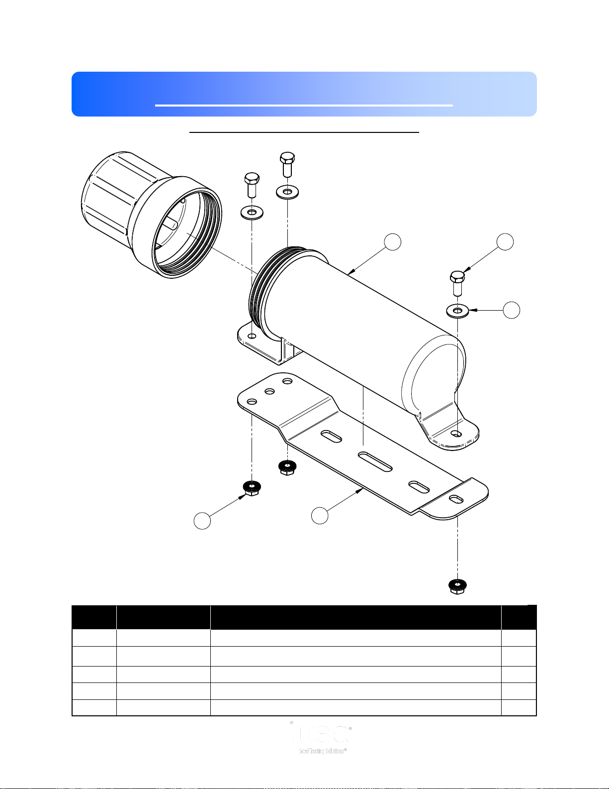
Section
ISOMETRIC VIEW
ASSEMBLED
1
2
3
4
5
I
PORTABLE LPV TREATER
Mechanical Drawings
MANUAL TUBE ASSEMBLY (13-05-0322)
Item # Part #
Page 38
Description Qty
1 06-01-0010
2 06-03-0019 NUT, FLG .3125-18 UNC ZP GRADE 5 3
3 06-05-0011 WASHER, .3125 FLAT 18-8 SS 3
4 08-07-0050 HOLDER MANUAL 3.25 DIA 1
5 103980 PLT MANUAL MT 1
BOLT .313-18 X 0.75 ZP GR5 3
Page 39
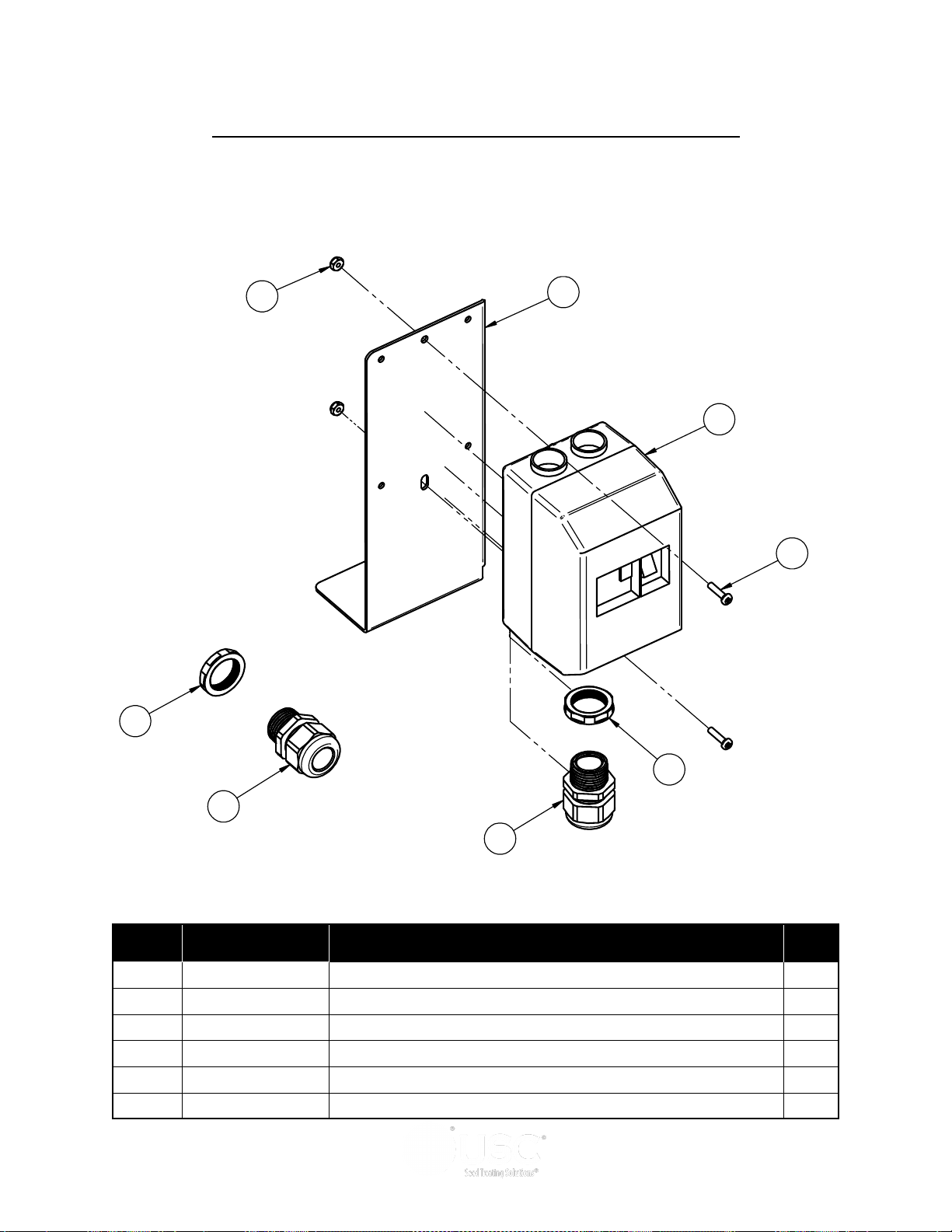
PORTABLE LPV TREATER
5
4
1
6
3
2
2
3
ELECTRIC POWER PACK SWITCH ASSEMBLY (03-13-0037)
Item # Part #
1 03-04-0136
2 03-08-0300 CONN CG .75NPT .450-.709 3235LTF 2
3 03-08-0309 NUT NYLOC .750 NPT 8466 2
4 05-10-2002 BRKT SW MP ENCL 1
5 06-03-0017 NUT,LOCK, #8-32 ZP NYLON INSERT 2
6 06-06-0012 SCRW MACH 8-32 X .750 PHLP RDHD ZP 2
MP MNL 24-32A 600V TMQ GV2ME32 1
Description Qty
Page 39
Page 40
PORTABLE LPV TREATER
SHEET 2 OF 2
U S C, L L C.
FILENAME: 13-08-0721A2 = HYD SW Kit
TITLE: ASSY ELEC PWR PK LPV PORT 230V 1PH
TOLERANCES
FRACTIONS: +/- 1/8"
DECIMALS: X.XX +/- .06", X.XXX +/-.031
ANGLES: +/- 1°
THIS MATERIAL IS THE
CONFIDENTIAL AND
PROPRIETARY PROPERTY OF
USC, LLC. AND SHALL NOT BE
USED WITHOUT PERMISSION.
06/08/17 at 8:45
REV: DWG#: 13-08-0721
1
3
5
7
8
9
10
11
12
13
14
18
21
20
15
19
18
2
6
16
4
17
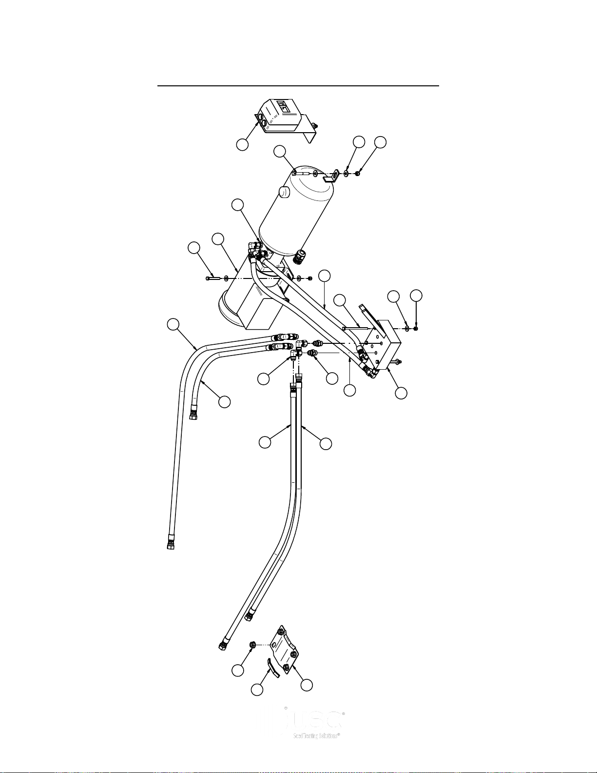
ELECTRIC POWER PACK ASSEMBLY (13-08-0721)
Page 40
Page 41

PORTABLE LPV TREATER
ELECTRIC POWER PACK ASSEMBLY (13-08-0721)
Item # Part #
1 01-01-0257
2 02-02-0125 VLV HYD 2 SPOOL 8GPM 1
3 02-05-0069 FTTG HYD STGHT 8MJ-8MOR 6
4 02-05-0074 FTTG HYD STGHT 8MJ-6MP 2
5 02-06-0059 FTTG HYD 90 DEG 8MJ-8FJX 8
6 03-13-0037 KIT SW MNL MP 110V 2 HP MTR 24-32A 1
7 06-01-0109 BOLT, .3125-18 UNC ZP G5; 2.25" LG 4
8 06-01-0116 BOLT .375-16 X 2.75 ZP GR5 2
9 06-01-0333 BOLT .3125-18 X 4.50 ZP GR5 3
10 06-03-0002 NUT NYL LOCK .313-18 ZP GR5 7
11 06-03-0003 NUT NYL LOCK .375-16 ZP GR5 2
12 06-03-0015 NUT LOCK FLG .500-13 ZP GR5 4
13 06-05-0003 WSHR FLAT .313 ZP 11
14 06-05-0004 WSHR FLAT .375 ZP 4
15 06-10-0025 EDGING SGRPG .375DP X .281W BLK 2
16 10564A HOSE RETAINER 1
17 13-05-0335 HHA .375ID 090.0IN -08FJX -08FJX 1
18 13-05-0397 HHA .375ID 031.2IN -08FJX -08FJX 1
19 13-05-0412 HHA .375ID 034.6IN -08FJX -08FJX 2
20 13-05-0599 HHA .375ID 109.0IN -08FJX -08FJX 1
21 13-05-0601 HHA .375ID 054.0IN -08FJX -08FJX 1
HYD PWR PK 2HP 1.0GPM 3000PSI 1
Description Qty
Page 41
Page 42
PORTABLE LPV TREATER
DRAWN
CHECKED
ENG APPR
NAME
davidw
DATE
09/27/2016
TITLE
SIZE
D
DWG NO
File Name:13-08-0653 = 5 HP DDrive.dft
SHEET 2 OF 3
UNLESS OTHERWISE SPECIFIED DIMENSIONS ARE IN
INCHES:
TOLERANCES:
FRACTIONS DECIMALS ANGL ES
± 1/32
.XX=±.03
.XXX=±.005
.XXXX=±.0005
±0.50°
DO NOT SCALE DRAWING
U S C, L L C.
Sabetha, Kansas 66534 USA
THIS MATERIAL IS THE CONFIDENTIAL AND PROPRIETARY PROPERTY OF
USC, LLC. AND SHALL NOT BE USED WITHOUT PERMISSION.
13-08-0653
Printed 09/29/16 at 7:22
DRAWN
CHECKED
ENG APPR
NAME
davidw
DATE
09/27/2016
TITLE
SIZE
D
DWG NO
File Name:13-08-0653 = 5 HP DDrive.dft
SHEET 2 OF 3
UNLESS OTHERWISE SPECIFIED DIMENSIONS ARE IN
INCHES:
TOLERANCES:
FRACTIONS DECIMALS ANGL ES
± 1/32
.XX=±.03
.XXX=±.005
.XXXX=±.0005
±0.50°
DO NOT SCALE DRAWING
U S C, L L C.
Sabetha, Kansas 66534 USA
THIS MATERIAL IS THE CONFIDENTIAL AND PROPRIETARY PROPERTY OF
USC, LLC. AND SHALL NOT BE USED WITHOUT PERMISSION.
13-08-0653
Printed 09/29/16 at 7:22
KIT DRIVE 5HP DD TS25
KIT DRIVE 5HP DD TS25
16
6
13
17
4
1
7
15
9
3
2
5
12
11
14
8
10
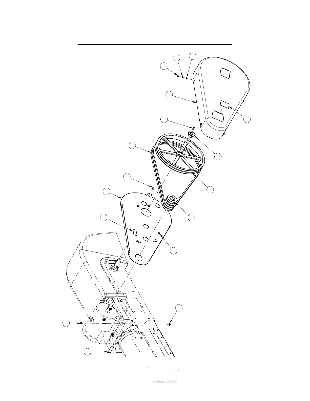
5 HP MOTOR DIRECT DRIVE ASSEMBLY (13-05-0653)
Page 42
Page 43

PORTABLE LPV TREATER
5 HP MOTOR DIRECT DRIVE ASSEMBLY (13-05-0653)
Item # Part #
1 01-02-0060
2 01-08-0120 SHEAVE 2BK190H 1
3 01-08-0121 BELT BX88 2
4 01-08-0122 SHV 2BK36 X 1.125 FHSH BORE 1
5 05-06-0127 CVR BELT DRV 1
6 06-01-0006 BOLT, .250-20 X .75 UNC ZP GRADE 5 5
7 06-01-0138 BOLT, FLG .3125-18 UNC ZP GRADE 5; 3/4" LG 4
8 06-01-0153 BOLT CRG .375-16X.750 ZP SHORT NECK 4
9 06-02-0047 NUT .250-20 U-CLIP NUT 5
10 06-03-0014 NUT LOCK FLG .375-16 ZP GR5 4
11 06-04-0001 WSHR LOCK SPLT .250 ZP 4
12 06-05-0001 WASHER, FLAT .250 4
13 09-02-0009 ATWK LBL WARNING ROTATING PARTS 1
14 09-02-0010 ATWK LBL DANGER ELECTROCUTION 1
15 09-02-0012 ATWK LBL DANGER MISSING SHIELD 1
16 104869 BACKPLATE BELT COVER 1
17 106-3-2036 KEY .250 X 1.25 CS 1
BUSH 1.000IN BORE TYPE H 1
Description Qty
Page 43
Page 44
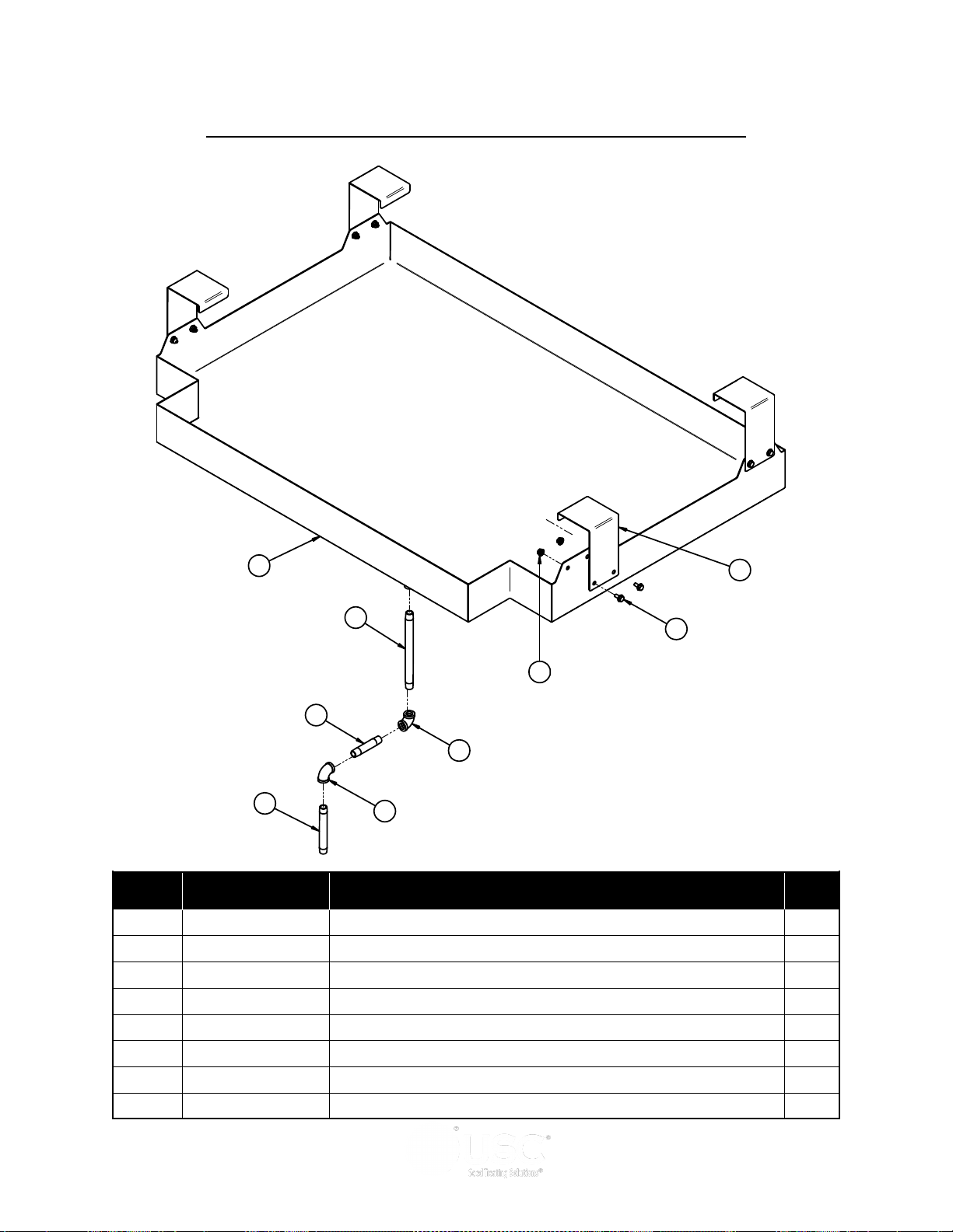
PORTABLE LPV TREATER
REVISION HISTORY
REV ECN DESCRIPTION DATE BY
A INITIAL DRAWING 3/2/2017 martyh
Item # Part # Rev Title Qty
1 02-06-0012 A FTTG 90 DEG .500NPT FM SS 2
2 02-07-0013 A FTTG NIP .500 NPT X 4.00 TBE SS 1
3 02-07-0015 A FTTG NIP .500 NPT X 6.00 TBE SS 1
4 02-07-0058 A FTTG NIP .500 NPT X 10.00 TBE SS 1
5 05-03-1711 A WDMT LPV CONTAIN PAN 1
6 06-01-0124 A BOLT FLG .375-16 X .750 ZP GR5 8
7 06-03-0014 A NUT LOCK FLG .375-16 ZP GR5 8
8 10577A A MNT HANGER 4
5
4
1
2
1
3
6
8
7
LPV TREATER CONTAINMENT PAN ASSEMBLY (13-05-0609)
Item # Part #
1 02-06-0012
FTTG 90 DEG .500NPT FM SS 2
Description Qty
2 02-07-0013 FTTG NIP .500 NPT X 4.00 TBE SS 1
3 02-07-0015 FTTG NIP .500 NPT X 6.00 TBE SS 1
4 02-07-0058 FTTG NIP .500 NPT X 10.00 TBE SS 1
5 05-03-1711 WDMT LPV CONTAIN PAN 1
6 06-01-0124 BOLT FLG .375-16 X .750 ZP GR5 8
7 06-03-0014 NUT LOCK FLG .375-16 ZP GR5 8
8 10577A MNT HANGER 4
Page 44
Page 45
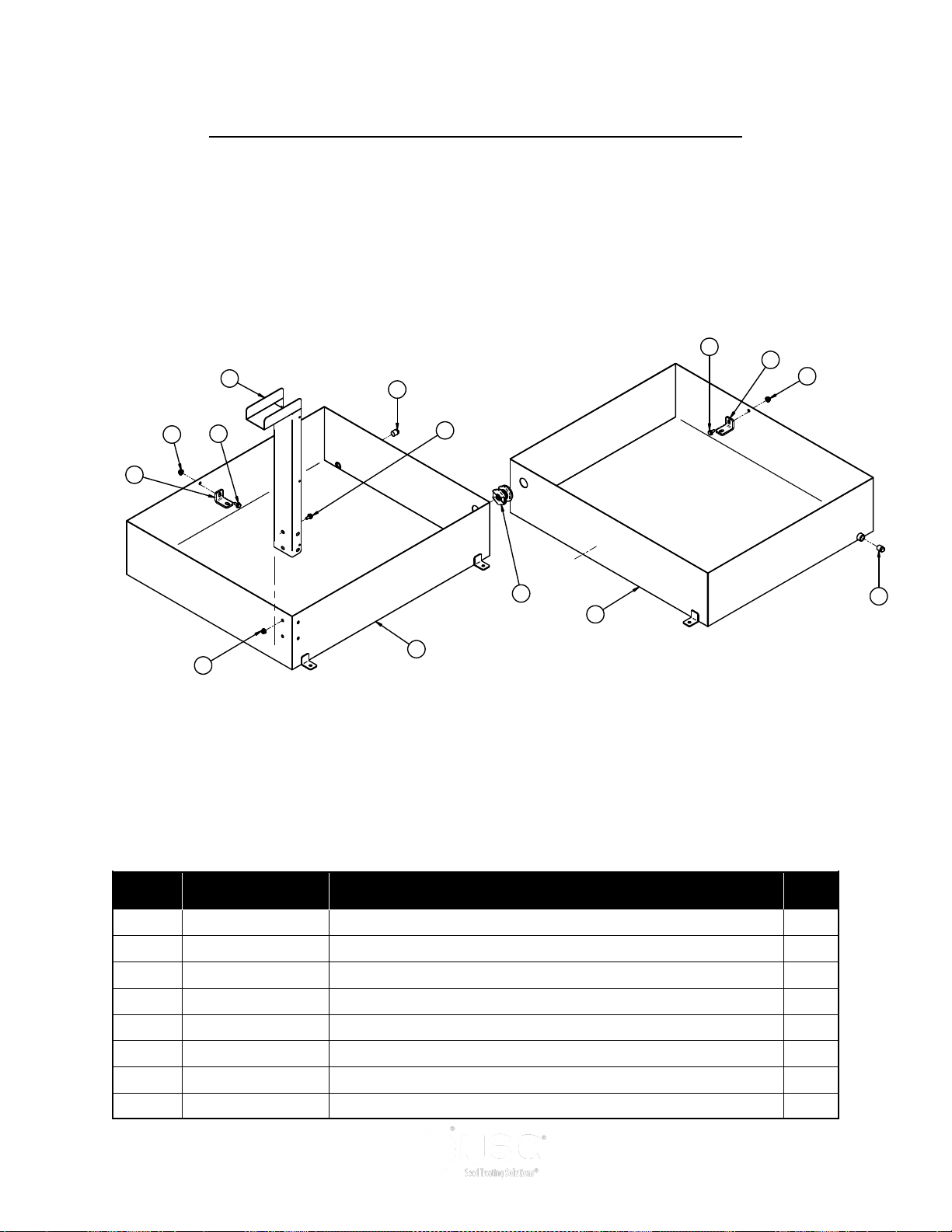
PORTABLE LPV TREATER
REVISION HISTORY
REV ECN DESCRIPTION DATE BY
A INITIAL DRAWING 3/2/2017 martyh
4
6
3
5
3
4
8
2
1
7
2
4
6
3
PUMP STAND CONTAINMENT PAN ASSEMBLY (13-05-0610)
Item # Part #
1 02-05-0045
Description Qty
FTTG .750 NPT DBL THD PPE BULKHEAD 1
2 02-14-0001 FTTG PLUG SQHD .500 NPT SS 2
3 06-01-0124 BOLT FLG .375-16 X .750 ZP GR5 6
4 06-03-0014 NUT LOCK FLG .375-16 ZP GR5 6
5 105784 WDMT HOSE CONTAINMENT 1
6 105785 MNT BRKT 2
7 10578B WDMT CONTAINMENT PAN 1
8 10578D WDMT CONTAINMENT PAN 1
Page 45
Page 46
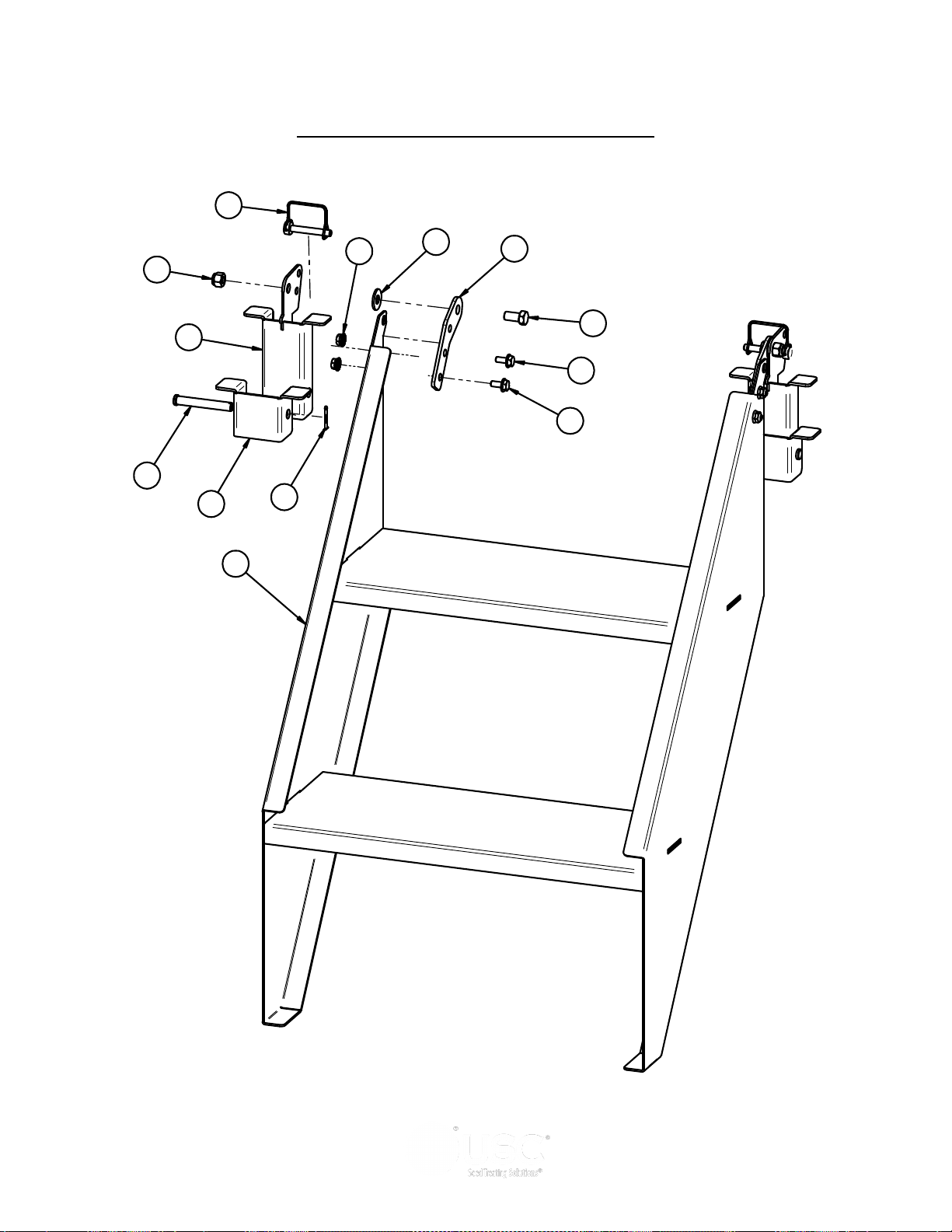
PORTABLE LPV TREATER
REV ECN DESCRIPTION DATE BY
A INITIAL DRAWING 11/23/16 ADW
001 REVISED HINGE 2/16/2017 martyh
Item # Part # Rev Title Qty
1 06-01-0069 A BOLT .500-13 X 1.00 ZP GR5 2
2 06-01-0124 A BOLT FLG .375-16 X .750 ZP GR5 4
3 06-03-0004 A NUT NYL LOCK .500-13 ZP GR5 2
4 06-03-0014 A NUT LOCK FLG .375-16 ZP GR5 4
5 06-05-0005 A WSHR FLAT .500 ZP 2
6 06-09-0005 A PIN CLVS .500 X 3.50 PLN 2
7 06-09-0079 A PIN SFTY .375 X 2.5 SQ DBL WIRE SNAP 2
8 06-09-0087 A .125 X 1.50 ZP COTTER PIN 2
9 1055CD A WDMT PORT STEP 1
10 105702 A WDMT HINGE 2
11 105740 A BRKT HINGE LOCK 2
12 10574A A PLT HINGE ARM 2
9
2
2
1
12
5
4
8
11
6
10
3
7
FOLD UP STEP ASSEMBLY (13-05-0592)
Page 46
Page 47

PORTABLE LPV TREATER
FOLD UP STEP ASSEMBLY (13-05-0592)
Item # Part #
1 06-01-0069
2 06-01-0124 BOLT FLG .375-16 X .750 ZP GR5 4
3 06-03-0004 NUT NYL LOCK .500-13 ZP GR5 2
4 06-03-0014 NUT LOCK FLG .375-16 ZP GR5 4
5 06-05-0005 WSHR FLAT .500 ZP 2
6 06-09-0005 PIN CLVS .500 X 3.50 PLN 2
7 06-09-0079 PIN SFTY .375 X 2.5 SQ DBL WIRE SNAP 2
8 06-09-0087 .125 X 1.50 ZP COTTER PIN 2
9 1055CD WDMT PORT STEP 1
10 105702 WDMT HINGE 2
11 105740 BRKT HINGE LOCK 2
12 10574A PLT HINGE ARM 2
BOLT .500-13 X 1.00 ZP GR5 2
Description Qty
Page 47
Page 48
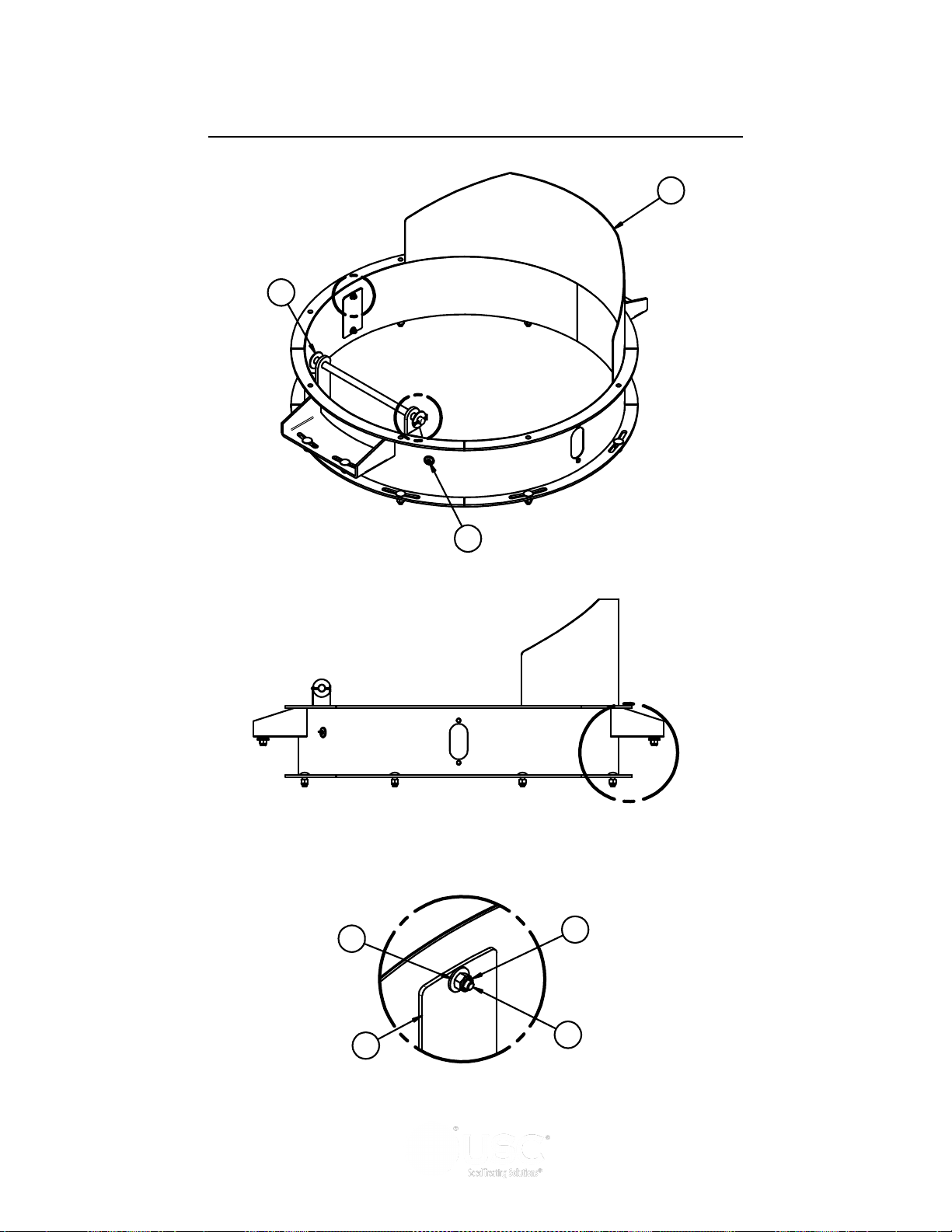
PORTABLE LPV TREATER
A
DETAIL A
7
5
3
2
1
B
DETAIL B
8
4
6
C
DETAIL C
12
TREATER INLET HOPPER EXTENSION ASSEMBLY (10550E)
Page 48
Page 49
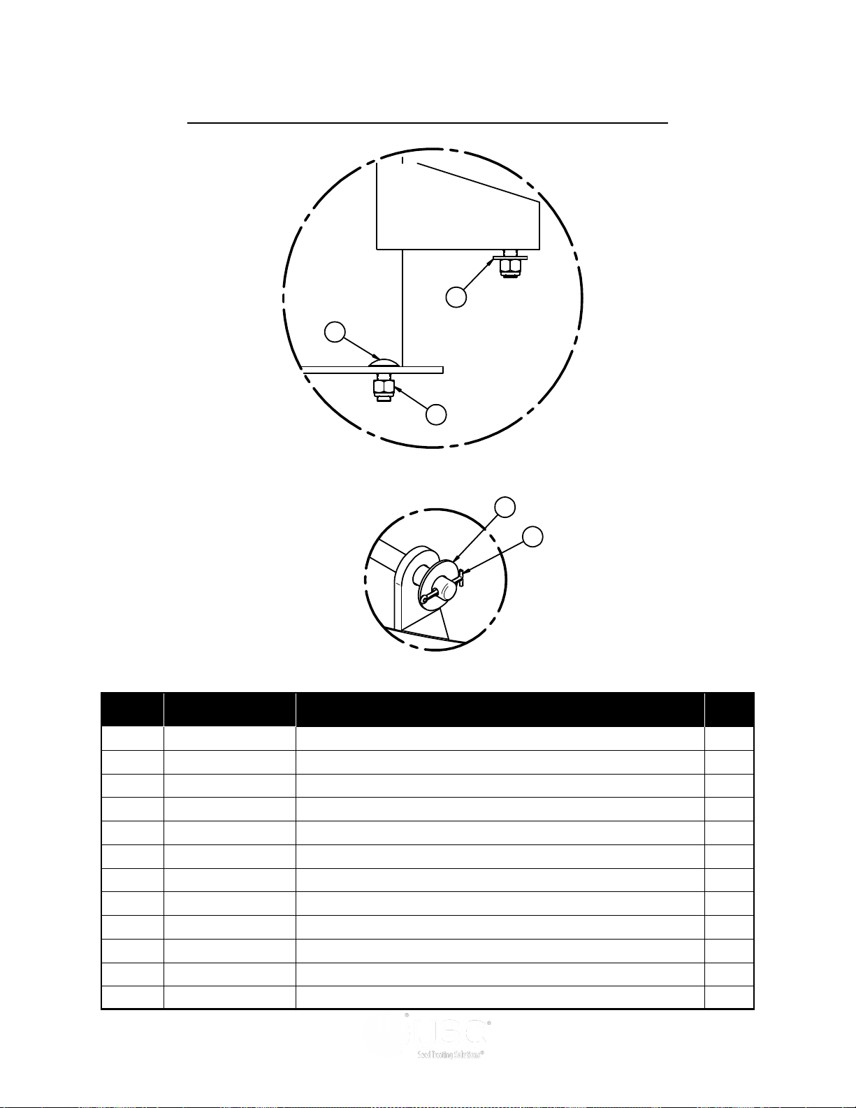
PORTABLE LPV TREATER
7
5
9
DETAIL B
DETAIL C
10
11
TREATER INLET HOPPER EXTENSION ASSEMBLY (10550E)
Item # Part #
1 03-08-0130
2 05-04-0016 WDMT FRONT PIVOT ROD 1
3 05-10-4064 PLT HOPP 6IN EXT VIEW 2
4 06-01-0006 BOLT, .250-20 X .75 UNC ZP GRADE 5 4
5 06-01-0062 BOLT CRG .500-13 X 1.25 ZP GR5 12
6 06-03-0001 NUT,LOCK, .250-20 ZP G5 NYLON INSERT 4
7 06-03-0004 NUT NYL LOCK .500-13 ZP GR5 12
8 06-05-0001 WASHER, FLAT .250 4
9 06-05-0005 WSHR FLAT .500 ZP 4
10 06-05-0007 WASHER, .750 FLAT ZP 1
11 06-09-0023 .188 X 2.00 ZP COTTER PIN 1
12 105510 WDMT 36ID X 8 INLET HOPP EXT CS 1
Description Qty
PLUG STEEL 22MM 1
Page 49
Page 50
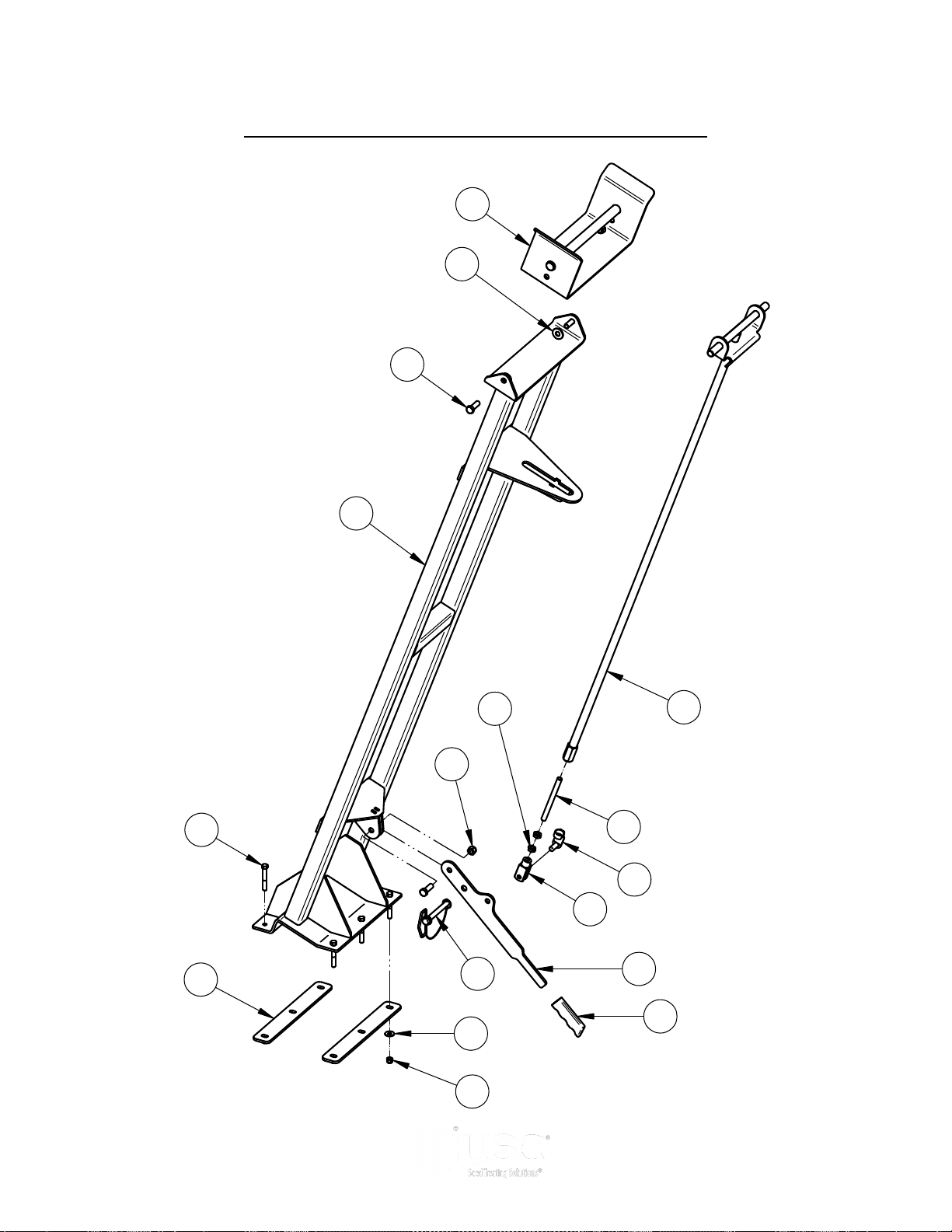
PORTABLE LPV TREATER
5
7
9
4
10
1
2
15
8
6
12
13
14
11
3
16
17
Item Number Document Number Quantity Title
1 05-03-1718 1 WDMT CNVR REST W/LK PORT
2 05-03-1719 1 WDMT CNVR REST W/LK PIVOT
3 05-03-1720 1 WDMT LATCH ROD
4 06-01-0025 3 BOLT .500-13 X 1.50 ZP GR5
5 06-01-0116 6 BOLT .375-16 X 2.75 ZP GR5
6 06-02-0015 2 NUT JAM .500-20 ZP GR5
7 06-03-0003 6 NUT NYL LOCK .375-16 ZP GR5
8 06-03-0004 3 NUT NYL LOCK .500-13 ZP GR5
9 06-05-0004 6 WSHR FLAT .375 ZP
10 06-05-0005 2 WSHR FLAT .500 ZP
11 06-09-0053 1 PIN HITCH .500 X 4.O LG W-LINCH PIN
12 06-09-0085 1 CLPSBL HOPP HNDL GRIP
13 06-12-0008 1 CLVS .500-20 X .500
14 06-12-0009 1 PIN CLIP SPRING .500
15 105748 2 PLT BACKING CNVR REST
16 1058EE 1 PLT LEVER LOCK
17 1059D4 1 ROD FTH .500-20 X 6.00
OUTLET CONVEYOR REST ASSEMBLY (13-05-0622)
Page 50
Page 51

PORTABLE LPV TREATER
OUTLET CONVEYOR REST ASSEMBLY (13-05-0622)
Item # Part #
1 05-03-1718
2 05-03-1719 WDMT CNVR REST W/LK PIVOT 1
3 05-03-1720 WDMT LATCH ROD 1
4 06-01-0025 BOLT .500-13 X 1.50 ZP GR5 3
5 06-01-0116 BOLT .375-16 X 2.75 ZP GR5 6
6 06-02-0015 NUT JAM .500-20 ZP GR5 2
7 06-03-0003 NUT NYL LOCK .375-16 ZP GR5 6
8 06-03-0004 NUT NYL LOCK .500-13 ZP GR5 3
9 06-05-0004 WSHR FLAT .375 ZP 6
10 06-05-0005 WSHR FLAT .500 ZP 2
11 06-09-0053 PIN HITCH .500 X 4.O LG W-LINCH PIN 1
12 06-09-0085 CLPSBL HOPP HNDL GRIP 1
13 06-12-0008 CLVS .500-20 X .500 1
14 06-12-0009 PIN CLIP SPRING .500 1
15 105748 PLT BACKING CNVR REST 2
16 1058EE PLT LEVER LOCK 1
17 1059D4 ROD FTH .500-20 X 6.00 1
WDMT CNVR REST W/LK PORT 1
Description Qty
Page 51
Page 52
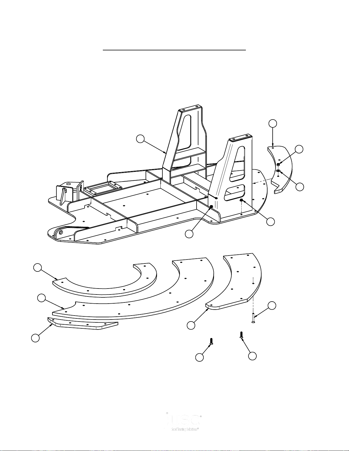
PORTABLE LPV TREATER
7
8
10
1
2
4
11
6
5
5
3
9
3
CONVEYOR PIVOT ASSEMBLY (13-05-0594)
Page 52
Page 53

PORTABLE LPV TREATER
CONVEYOR PIVOT ASSEMBLY (13-05-0594)
Item # Part #
1 05-03-1691
2 06-03-0003 NUT NYL LOCK .375-16 ZP GR5 3
3 06-03-0014 NUT LOCK FLG .375-16 ZP GR5 24
4 06-05-0004 WSHR FLAT .375 ZP 3
5 06-06-0070 SCRW MACH .375-16 X 1.50 SH FLHD BO 24
6 06-06-0107 SCRW MACH .375-16 X 2.50 SH FLHD BO 3
7 1054FC PIVOT PLT BTM SLIDE 1 1
8 1054FD PIVOT PLT BTM SLIDE 2 1
9 1054FE PIVOT PLT BTM SLIDE 3 1
10 1055AC PIVOT PLT BTM SLIDE 4 1
11 1059D5 PIVOT PLT TOP SLIDE 1
WDMT PIVOT PLT 1
Description Qty
Page 53
Page 54
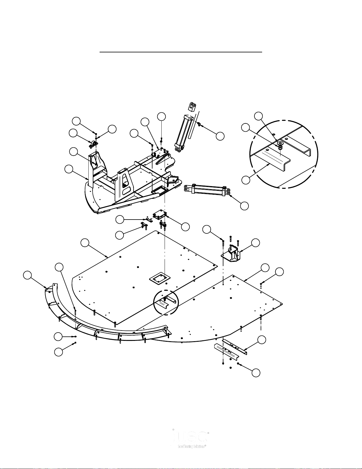
PORTABLE LPV TREATER
11
9
12
18
3
5
20
21
22
19
24
10
15
16
1
2
8
4
6
7
23
A
DETAIL A
21
14
14
17
13
15
LPV PORTABLE PIVOT ASSEMBLY (13-05-0594)
Page 54
Page 55

PORTABLE LPV TREATER
LPV PORTABLE PIVOT ASSEMBLY (13-05-0594)
Item # Part #
1 01-03-0060
2 02-06-0058 FTTG HYD 90 DEG 8MJ-8MOR 4
3 03-17-0133 CYL HYD 14IN STRK 3.0IN ID 2
4 05-03-1706 WDMT BOLT HLDR 2
5 05-03-1708 WDMT CYLN MNT LPV PORT 1
6 05-03-1709 WDMT DECK PLT TURNTABLE 1
7 05-03-1710 WDMT BOLT HLDR LG 2
8 06-01-0024 BOLT .500-13 X .750 ZP GR5 6
9 06-01-0029 BOLT .500-13 X 3.25 ZP GR5 4
10 06-01-0054 BOLT .500-13 X 1.75 ZP GR5 4
11 06-01-0116 BOLT .375-16 X 2.75 ZP GR5 16
12 06-01-0252 BOLT .500-13 X 3.00 ZP GR5 24
13 06-03-0003 NUT NYL LOCK .375-16 ZP GR5 16
14 06-03-0004 NUT NYL LOCK .500-13 ZP GR5 32
15 06-03-0015 NUT LOCK FLG .500-13 ZP GR5 8
16 06-04-0004 WSHR LOCK SPLT .500 ZP 10
17 06-05-0004 WSHR FLAT .375 ZP 16
18 06-05-0005 WSHR FLAT .500 ZP 6
19 06-08-0007 TURNTABLE 1500LB 1
20 105516 WDMT PIVOT RETAINER 1
21 105726 PIVOT SUPPT BRKT 4
22 105752 PLT LPV PORT PIVOT 1
BRG PLW SEALED 1.00ID STSC 2
Description Qty
23 10575A PLT PIVOT MNT 1
24 13-05-0586 ASSY CNVR PIVOT PLT 1
Page 55
Page 56
PORTABLE LPV TREATER
REV DESCRIPTION DATE BY
B
DELETE 05-10-2138, 06-10-0060, 103F37, 103F38, 103F3C, 103F3D, 103FB4, 103FB5. ADD
05-08-0536, 10472A, 1047FE, 1047FF, 104800, 104803, 104804, 13-05-0478, 13-05-0479
002
REVISE 13-08-0478 & 13-08-0479 FROM A TO B, DELETE 1047FE, 1047FF, 104803, 104804,
06-12-0022, ADD 13-05-0582, 13-05-0583, 06-02-0100
C
REVISE 05-08-0477 FROM A TO B, REV 13-05-0582 & 13-05-0583 FROM A TO B, REV 10472A
FROM A TO B, DELETE 104800, ADD 105608
6
7
3
9
4
10
1
17
18
12
14
11
2
13
15
16
8
Item Number Document Number REV Quantity Title
10 06-03-0014 A 4 NUT LOCK FLG .375-16 ZP GR5
11 06-03-0019 A 16 NUT LOCK FLG .3125-18 ZP GR5
12 103D17 A 2 PLT SKIRT SPACER
13 10472A B 1 EAR BRUSH MNT
14 105608 A 1 COVER CLN\OUT
15 13-05-0478 B 1 ASSY BRUSH W\CLIPS 11.25
16 13-05-0479 B 1 ASSY BRUSH W\CLIPS 11.88
17 13-05-0582 B 1 ASSY SKIRT RH TS25
18 13-05-0583 B 1 ASSY SKIRT RIGID TS25
5
10
3
9
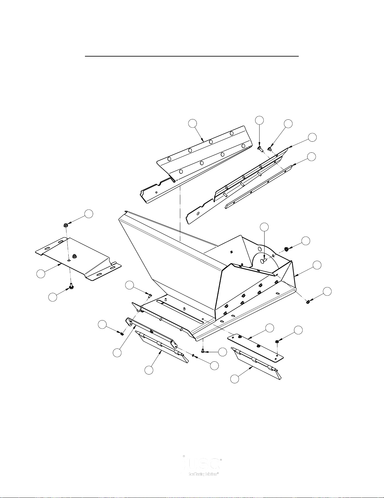
INLET CONVEYOR INLET HOPPER ASSEMBLY (13-08-0540)
Page 56
Page 57

PORTABLE LPV TREATER
INLET CONVEYOR INLET HOPPER ASSEMBLY (13-08-0540)
Item # Part #
1 05-08-0477
2 05-08-0536 WDMT PIVOT BRSH PLT TS25 1
3 06-01-0004 BOLT, .250-20 X .500 UNC ZP GRADE 5 6
4 06-01-0115 BOLT CRG .375-16 X 1.00 ZP GR5 2
5 06-01-0124 BOLT FLG .375-16 X .750 ZP GR5 2
6 06-01-0129 BOLT CRG .313-18 X .50 ZP GR5 8
7 06-01-0223 BOLT CRG .313-18 X 1.00 ZP GR5 8
8 06-02-0100 PUSH NUT SS .250 UNTHREADED 2
9 06-03-0013 NUT,LOCK, FLG .250-20 ZP SERRATTED 6
10 06-03-0014 NUT LOCK FLG .375-16 ZP GR5 4
11 06-03-0019 NUT LOCK FLG .3125-18 ZP GR5 16
12 103D17 PLT SKIRT SPACER 2
13 10472A EAR BRUSH MNT 1
14 105608 COVER CLN\OUT 1
15 13-05-0478 ASSY BRUSH W\CLIPS 11.25 1
16 13-05-0479 ASSY BRUSH W\CLIPS 11.88 1
17 13-05-0582 ASSY SKIRT RH TS25 1
18 13-05-0583 ASSY SKIRT RIGID TS25 1
WDMT LG INLET 8IN RND 1
Description Qty
Page 57
Page 58
DRAWN
CHECKED
ENG APPR
UNLESS OTHERWISE SPECIFIED DIMENSIONS ARE IN INCHES:
DECIMALS ANGLES
.XX=±.06
.XXX=±.031
THIS MATERIAL IS THE CONFIDENTIAL AND PROPRIETARY PROPERTY OF
NOTES:
TAKE-UP SLIDES MUST BE ABLE TO MOVE FREELY AFTER BEARING IS TIGHT.
ZERKS ARE TO BE POINTED UP ON BOTH SIDES.
SLIDES SHOULD NOT CONTACT TRANSITION WELDMENT, 2 PLCS.
1.
2.
3.
17
12
11
18
14
7
9
10
15
19
21
8
13
16
23
24
1
2
5
4
26
25
3
22
20
Item Number Document Number Quantity Title
1 01-03-0042 2 BRG FLG MNT 1.000ID 2BOLT ECNTRC
2 01-08-0108 1 PULLEY TAIL W-LAGGING
3 05-08-0404 2 WDMT TAKE-UP PLT RND CNVR
4 05-08-0419 1 WDMT SPLICE 12IN
5 05-08-0569 1 WDMT TAIL TRANS TS25
6 05-10-4339 2 PLT STOP MOUNT
7 06-01-0013 4 BOLT, .312-18 UNC ZP GRADE 5; 1.50" LG
8 06-01-0027 2 BOLT .500-13 X 2.00 ZP GR5
9 06-01-0115 4 BOLT CRG .375-16 X 1.00 ZP GR5
10 06-01-0124 2 BOLT FLG .375-16 X .750 ZP GR5
11 06-01-0150 4 BOLT, CARRIAGE, .250-20x.50 G5 ZP
12 06-01-0153 22 BOLT CRG .375-16X.750 ZP SHORT NECK
13 06-01-0249 2 BOLT .625-11 X 9.00 ZP GR5 FTH
14 06-01-0261 12 BOLT FLG .3125-18 X .500 ZP GR5
15 06-02-0003 4 NUT FULL .375-16 ZP GR5
16 06-02-0005 4 NUT, .625-11 UNC ZP GRADE 5
17 06-03-0004 2 NUT NYL LOCK .500-13 ZP GR5
18 06-03-0013 4 NUT,LOCK, FLG .250-20 ZP SERRATTED
19 06-03-0014 28 NUT LOCK FLG .375-16 ZP GR5
20 06-04-0002 4 WSHR LOCK SPLT .313 ZP
21 06-04-0003 4 WSHR LOCK SPLT .375 ZP
22 06-05-0003 4 WSHR FLAT .313 ZP
23 06-05-0006 4 WASHER, .625 FLAT ZP
24 06-09-0066 2 KNOB .375 -16 X 1. 4 LUG PLASTIC
25 104241 1 PLT TAKE-UP CVR
26 13-05-0523 1 ASSY INLET FRAME W/RIVETNUTS TS25
6
14
19
PORTABLE LPV TREATER
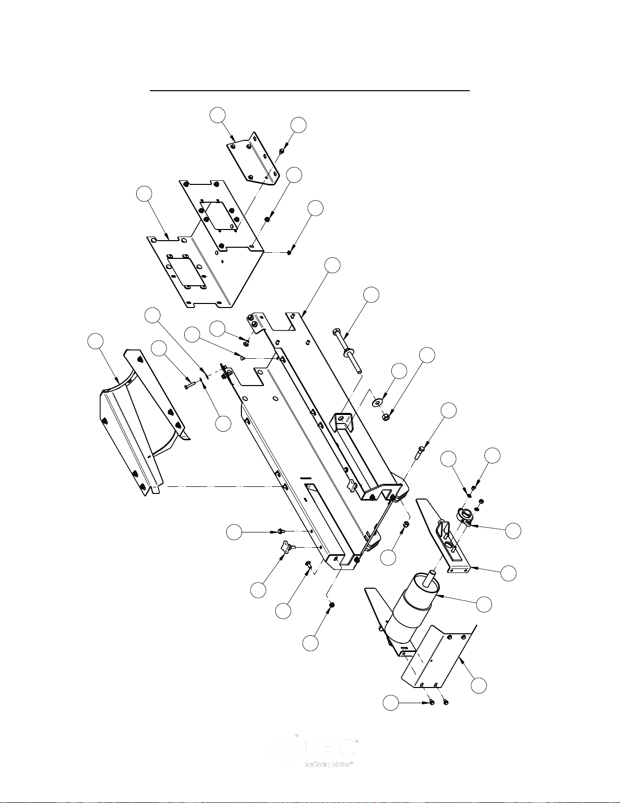
INLET CONVEYOR INLET END ASSEMBLY (13-08-0532)
Page 58
Page 59

PORTABLE LPV TREATER
INLET CONVEYOR INLET END ASSEMBLY (13-08-0532)
Item # Part #
1 01-03-0042
2 01-08-0108 PULLEY TAIL W-LAGGING 1
3 05-08-0404 WDMT TAKE-UP PLT RND CNVR 2
4 05-08-0419 WDMT SPLICE 12IN 1
5 05-08-0569 WDMT TAIL TRANS TS25 1
6 05-10-4339 PLT STOP MOUNT 2
7 06-01-0013 BOLT, .312-18 UNC ZP GRADE 5; 1.50" LG 4
8 06-01-0027 BOLT .500-13 X 2.00 ZP GR5 2
9 06-01-0115 BOLT CRG .375-16 X 1.00 ZP GR5 4
10 06-01-0124 BOLT FLG .375-16 X .750 ZP GR5 2
11 06-01-0150 BOLT, CARRIAGE, .250-20x.50 G5 ZP 4
12 06-01-0153 BOLT CRG .375-16X.750 ZP SHORT NECK 22
13 06-01-0249 BOLT .625-11 X 9.00 ZP GR5 FTH 2
14 06-01-0261 BOLT FLG .3125-18 X .500 ZP GR5 12
15 06-02-0003 NUT FULL .375-16 ZP GR5 4
16 06-02-0005 NUT, .625-11 UNC ZP GRADE 5 4
17 06-03-0004 NUT NYL LOCK .500-13 ZP GR5 2
18 06-03-0013 NUT,LOCK, FLG .250-20 ZP SERRATTED 4
19 06-03-0014 NUT LOCK FLG .375-16 ZP GR5 28
20 06-04-0002 WSHR LOCK SPLT .313 ZP 4
21 06-04-0003 WSHR LOCK SPLT .375 ZP 4
22 06-05-0003 WSHR FLAT .313 ZP 4
23 06-05-0006 WASHER, .625 FLAT ZP 4
24 06-09-0066 KNOB .375 -16 X 1. 4 LUG PLASTIC 2
25 104241 PLT TAKE-UP CVR 1
26 13-05-0523 ASSY INLET FRAME W/RIVETNUTS TS25 1
BRG FLG MNT 1.000ID 2BOLT ECNTRC 2
Description Qty
Page 59
Page 60
PORTABLE LPV TREATER
4
7
6
5
8
1
2
9
Item Number Document Number REV Quantity Title
1 05-08-0419 A 1 WDMT SPLICE 12IN
2 05-08-0461 B 1 WDMT TUBE 8.00IN X 84.86IN
3 05-08-0610 A 1 WDMT CLEAN OUT
4 05-10-4524 A 1 FRAME INLET SEC CLN OUT
5 06-01-0124 A 8 BOLT FLG .375-16 X .750 ZP GR5
6 06-01-0138 A 16 BOLT, FLG .3125-18 UNC ZP GRADE 5; 3/4" LG
7 06-01-0150 A 4 BOLT, CARRIAGE, .250-20x.50 G5 ZP
8 06-01-0153 A 32 BOLT CRG .375-16X.750 ZP SHORT NECK
9 06-01-0261 A 8 BOLT FLG .3125-18 X .500 ZP GR5
10 06-01-0311 A 1 BOLT .313-18 X 3.25 ZP GR5
11 06-02-0092 A 16 RIVETNUT .312-18 ZP
12 06-03-0002 A 1 NUT NYL LOCK .313-18 ZP GR5
13 06-03-0013 A 4 NUT,LOCK, FLG .250-20 ZP SERRATTED
14 06-03-0014 A 40 NUT LOCK FLG .375-16 ZP GR5
15 103B9A A 2 PLT SPLICE COVER
16 1050CF A 1 PLT DOOR CLEAN OUT
17 1050E8 A 1 PLT BELT GUIDE
NOTES:
RIVETNUTS ARE TO BE FULLY SEATED WHEN INSTALLED, 16 PLCS.
TO PREVENT THREAD DAMAGE, DO NOT OVER TIGHTEN OR CROSS-THREAD BOLTS WHEN INSTALLING.
DIRECTIONAL ARROW IN PAN SHOULD POINT TOWARDS DISCHARGE HEAD.
MAKE SURE CLEAN OUT DOOR IS INSTALLED AND RETAINED WITH BOLT AND NUT.
1.
2.
3.
4.
11
13
14
15
11
16
17
10
12
14
14
3
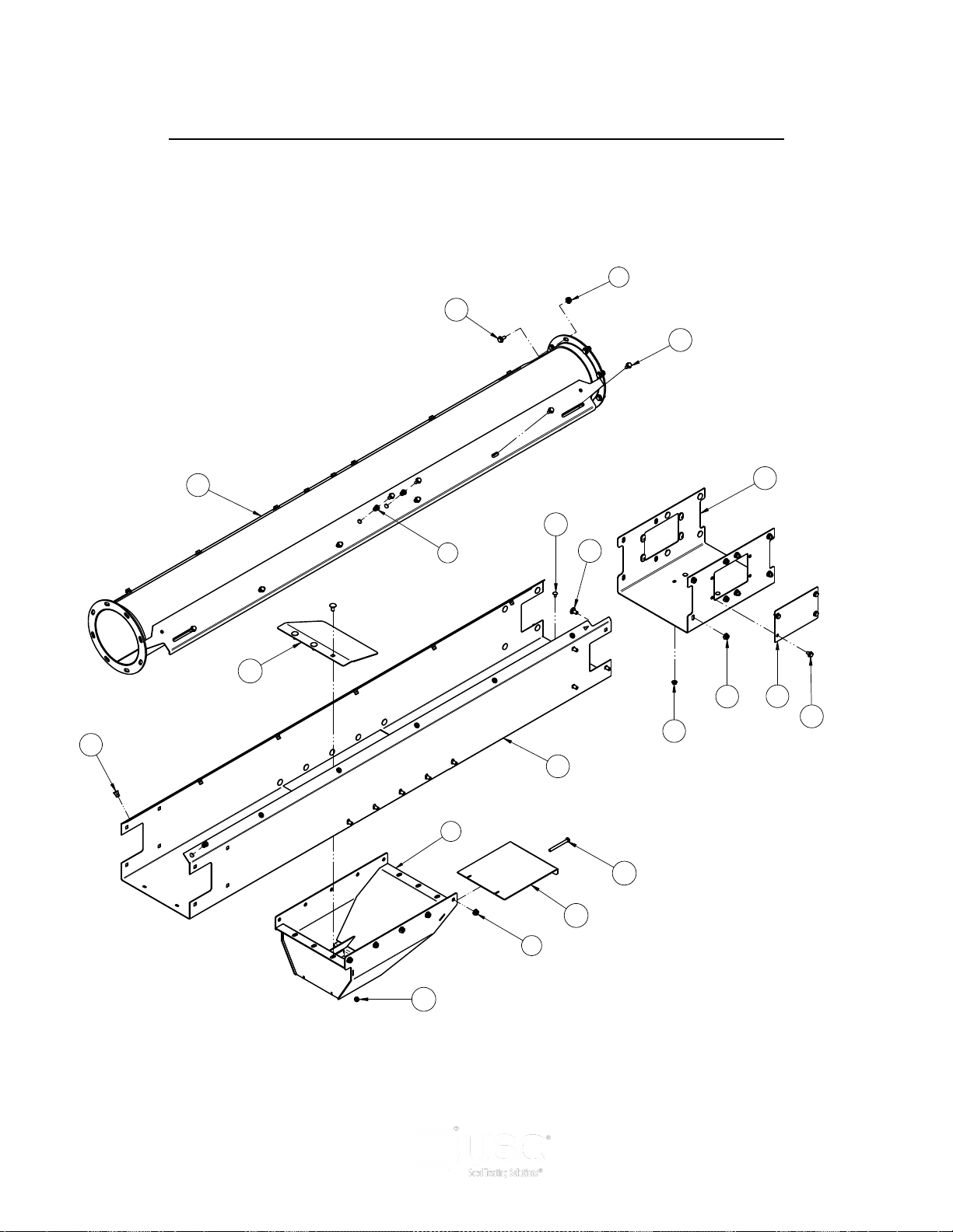
INLET CONVEYOR EXTENSION CLEAN OUT ASSEMBLY (13-08-0668)
Page 60
Page 61

PORTABLE LPV TREATER
INLET CONVEYOR EXTENSION CLEAN OUT ASSEMBLY (13-08-0668)
Item # Part #
1 05-08-0419
2 05-08-0461 WDMT TUBE 8.00IN X 84.86IN 1
3 05-08-0610 WDMT CLEAN OUT 1
4 05-10-4524 FRAME INLET SEC CLN OUT 1
5 06-01-0124 BOLT FLG .375-16 X .750 ZP GR5 8
6 06-01-0138 BOLT, FLG .3125-18 UNC ZP GRADE 5; 3/4" LG 16
7 06-01-0150 BOLT, CARRIAGE, .250-20x.50 G5 ZP 4
8 06-01-0153 BOLT CRG .375-16X.750 ZP SHORT NECK 32
9 06-01-0261 BOLT FLG .3125-18 X .500 ZP GR5 8
10 06-01-0311 BOLT .313-18 X 3.25 ZP GR5 1
11 06-02-0092 RIVETNUT .312-18 ZP 16
12 06-03-0002 NUT NYL LOCK .313-18 ZP GR5 1
13 06-03-0013 NUT,LOCK, FLG .250-20 ZP SERRATTED 4
14 06-03-0014 NUT LOCK FLG .375-16 ZP GR5 40
15 103B9A PLT SPLICE COVER 2
16 1050CF PLT DOOR CLEAN OUT 1
17 1050E8 PLT BELT GUIDE 1
WDMT SPLICE 12IN 1
Description Qty
Page 61
Page 62
PORTABLE LPV TREATER
1
6
2
5
3
4
Item Number Document Number Quantity Title
1 05-08-0661 1 WDMT SPOUT MNT
2 06-01-0006 4 BOLT .250-20 X .750 ZP GR5
3 06-05-0004 2 WSHR FLAT .375 ZP
4 06-05-0005 2 WSHR FLAT .500 ZP
5 06-09-0001 2 KNOB 3PRONG 1.25IN
6 105429 1 PLT ADJ SPOUT
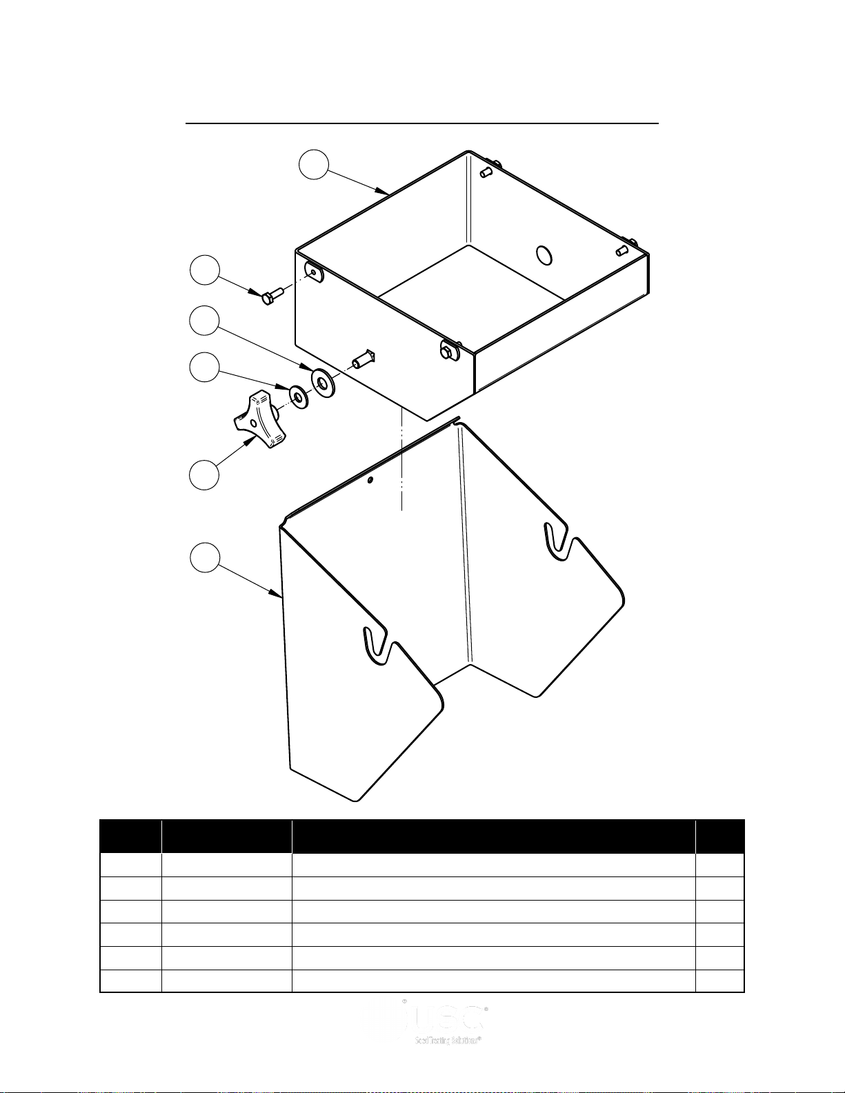
ADJUSTABLE DISCHARGE SPOUT ASSEMBLY (13-08-0705)
Item # Part #
1 05-08-0661
2 06-01-0006 BOLT .250-20 X .750 ZP GR5 4
3 06-05-0004 WSHR FLAT .375 ZP 2
4 06-05-0005 WSHR FLAT .500 ZP 2
5 06-09-0001 KNOB 3PRONG 1.25IN 2
6 105429 PLT ADJ SPOUT 1
Page 62
WDMT SPOUT MNT 1
Description Qty
Page 63
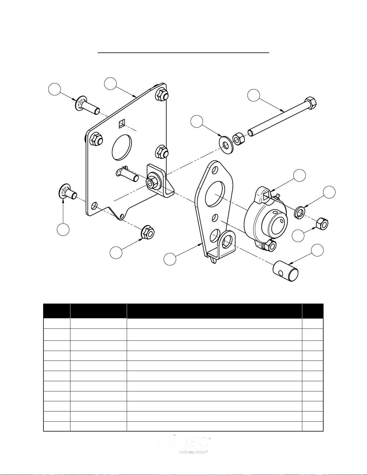
PORTABLE LPV TREATER
REV DESCRIPTION DATE BY
A INITIAL DRAWING 03/19/15 LGH
5
4
6
7
8
10
9
1
2
3
11
HEAD TRACKING PLATE ASSEMBLY (13-08-0564)
Item # Part #
1 01-03-0042
2 05-08-0484 WDMT TRACKING PIVOT 1
3 05-08-0494 WDMT TRACKING PLT HD 1
4 06-01-0127 BOLT CRG .375-16 X 1.25 ZP GR5 2
5 06-01-0153 BOLT CRG .375-16X.750 ZP SHORT NECK 4
6 06-01-0247 BOLT .375-16X4.5 HE G5 ZP FTH 1
7 06-02-0003 NUT FULL .375-16 ZP GR5 4
8 06-03-0014 NUT LOCK FLG .375-16 ZP GR5 4
9 06-04-0003 WSHR LOCK SPLT .375 ZP 2
10 06-05-0004 WSHR FLAT .375 ZP 2
11 104079 PIN TRACKING PIVOT 1
BRG FLG MNT 1.000ID 2BOLT ECNTRC 1
Description Qty
Page 63
Page 64
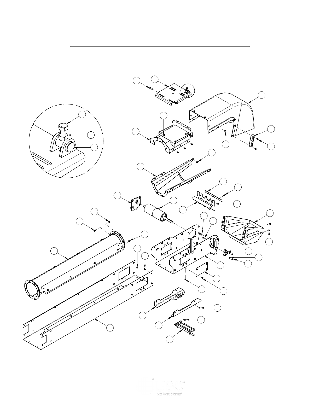
PORTABLE LPV TREATER
A
DETAIL A
20
23
21
24
19
29
5
30
1
2
7
35
31
4
17
18
14
22
25
26
3
32
36
8
6
9
10
34
Item Number Document Number REV Quantity Title
1 01-03-0042 A 1 BRG FLG MNT 1.000ID 2BOLT ECNTRC
2 01-08-0109 A 1 PULLEY HEAD VULC TS2500
3 05-06-0131 A 1 COVER HD TS25 DD
4 05-08-0414 B 1 WDMT TUBE 8.00IN X 60IN
5 05-08-0529 A 1 WDMT LOCK PORT CNVR
6 05-08-0549 A 1 WDMT MTR MNT PLT LG
7 05-08-0564 A 1 WDMT HD TRANS TS25
8 05-08-0565 A 1 WDMT HD CVR TS25
9 05-08-0566 A 1 WDMT DSCHG HD TS25
10 05-08-0567 A 1 WDMT DSCHG HD SPOUT TS25
11 05-08-0568 A 2 WDMT DSCHG HD MNT PLT
12 05-10-4359 B 1 BRKT MNT PORT RH
13 05-10-4361 B 1 BRKT MNT PORT LH
14 06-01-0080 A 2 BOLT .500-13 X 1.25 ZP GR5
15 06-01-0115 A 4 BOLT CRG .375-16 X 1.00 ZP GR5
16 06-01-0122 A 3 BOLT, CARRIAGE, .250-20x.75 G5 ZP
17 06-01-0124 A 10 BOLT FLG .375-16 X .750 ZP GR5
18 06-01-0127 A 2 BOLT CRG .375-16 X 1.25 ZP GR5
19 06-01-0138 A 16 BOLT, FLG .3125-18 UNC ZP GRADE 5; 3/4" LG
20 06-01-0150 A 6 BOLT, CARRIAGE, .250-20x.50 G5 ZP
21 06-01-0153 A 32 BOLT CRG .375-16X.750 ZP SHORT NECK
22 06-01-0157 A 1 BOLT, .500-13 X 4" UNC ZP GRADE 5 fth
23 06-01-0261 A 8 BOLT FLG .3125-18 X .500 ZP GR5
24 06-02-0003 A 2 NUT FULL .375-16 ZP GR5
25 06-02-0004 A 1 NUT FULL .500-13 ZP GR5
26 06-03-0004 A 2 NUT NYL LOCK .500-13 ZP GR5
27 06-03-0013 A 9 NUT,LOCK, FLG .250-20 ZP SERRATTED
28 06-03-0014 A 42 NUT LOCK FLG .375-16 ZP GR5
29 06-04-0003 A 2 WSHR LOCK SPLT .375 ZP
30 103B39 A 1 PLT SCRAPER HLDR 12IN CNVR
31 103B9A A 2 PLT SPLICE COVER
32 10414A A 1 PIN MTR PIVOT
33 104259 A 1 RBBR SCRAPER 12IN FILL
34 104C11 B 1 PLT BAFFLE MNT
35 13-05-0529 A 1 ASSY FRAME HD TS2532 W/RIVETNUTS
36 13-08-0564 A 1 ASSY TRACKING PLT HD
12
15
11
33
27
28
16
13
28
19
17
28
28
21
INLET CONVEYOR HEAD SECTION ASSEMBLY (13-08-0737)
Page 64
Page 65

PORTABLE LPV TREATER
INLET CONVEYOR HEAD SECTION ASSEMBLY (13-08-0737)
Item # Part #
1 01-03-0042
2 01-08-0109 PULLEY HEAD VULC TS2500 1
3 05-06-0131 COVER HD TS25 DD 1
4 05-08-0414 WDMT TUBE 8.00IN X 60IN 1
5 05-08-0529 WDMT LOCK PORT CNVR 1
6 05-08-0549 WDMT MTR MNT PLT LG 1
7 05-08-0564 WDMT HD TRANS TS25 1
8 05-08-0565 WDMT HD CVR TS25 1
9 05-08-0566 WDMT DSCHG HD TS25 1
10 05-08-0567 WDMT DSCHG HD SPOUT TS25 1
11 05-08-0568 WDMT DSCHG HD MNT PLT 2
12 05-10-4359 BRKT MNT PORT RH 1
13 05-10-4361 BRKT MNT PORT LH 1
14 06-01-0080 BOLT .500-13 X 1.25 ZP GR5 2
15 06-01-0115 BOLT CRG .375-16 X 1.00 ZP GR5 4
16 06-01-0122 BOLT, CARRIAGE, .250-20x.75 G5 ZP 3
17 06-01-0124 BOLT FLG .375-16 X .750 ZP GR5 10
18 06-01-0127 BOLT CRG .375-16 X 1.25 ZP GR5 2
19 06-01-0138 BOLT, FLG .3125-18 UNC ZP GRADE 5; 3/4" LG 16
20 06-01-0150 BOLT, CARRIAGE, .250-20x.50 G5 ZP 6
21 06-01-0153 BOLT CRG .375-16X.750 ZP SHORT NECK 32
22 06-01-0157 BOLT, .500-13 X 4" UNC ZP GRADE 5 fth 1
BRG FLG MNT 1.000ID 2BOLT ECNTRC 1
Description Qty
23 06-01-0261 BOLT FLG .3125-18 X .500 ZP GR5 8
24 06-02-0003 NUT FULL .375-16 ZP GR5 2
25 06-02-0004 NUT FULL .500-13 ZP GR5 1
26 06-03-0004 NUT NYL LOCK .500-13 ZP GR5 2
27 06-03-0013 NUT,LOCK, FLG .250-20 ZP SERRATTED 9
28 06-03-0014 NUT LOCK FLG .375-16 ZP GR5 42
29 06-04-0003 WSHR LOCK SPLT .375 ZP 2
30 103B39 PLT SCRAPER HLDR 12IN CNVR 1
31 103B9A PLT SPLICE COVER 2
32 10414A PIN MTR PIVOT 1
33 104259 RBBR SCRAPER 12IN FILL 1
34 104C11 PLT BAFFLE MNT 1
35 13-05-0529 ASSY FRAME HD TS2532 W/RIVETNUTS 1
36 13-08-0564 ASSY TRACKING PLT HD 1
Page 65
Page 66
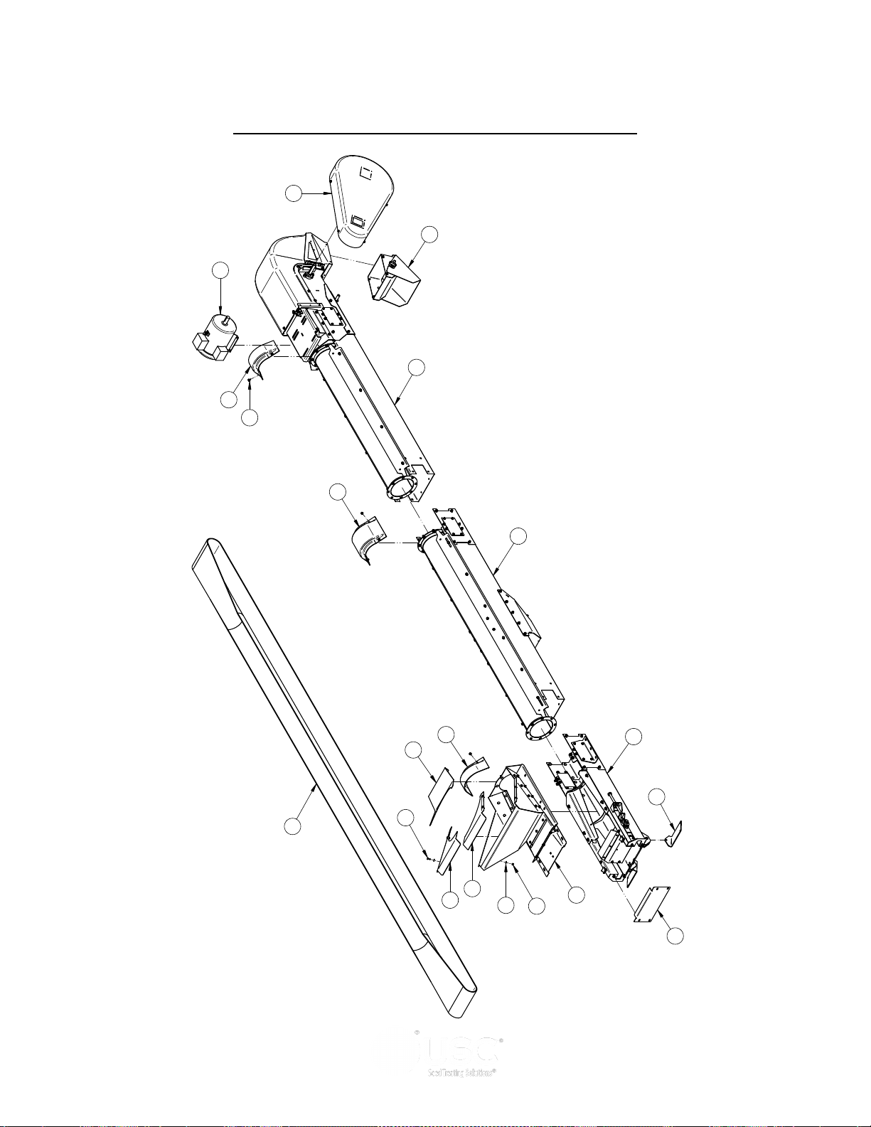
PORTABLE LPV TREATER
DRAWN
CHECKED
ENG APPR
NAME
davidw
DATE
03/27/2017
TITLE
SIZE
D
DWG NO
File Name:17-13-0028 = 17FT Inlet Cnvr.dft
SHEET 2 OF 2
UNLESS OTHERWISE SPECIFIED DIMENSIONS ARE IN
INCHES:
TOLERANCES:
FRACTIONS DECIMALS ANGLES
± 1/32
.XX=±.03
.XXX=±.005
.XXXX=±.0005
±0.50°
DO NOT SCALE DRAWING
U S C, L L C.
Sabetha, Kansas 66534 USA
THIS MATERIAL IS THE CONFIDENTIAL AND PROPRIETARY PROPERTY OF
USC, LLC. AND SHALL NOT BE USED WITHOUT PERMISSION.
17-13-0028
Printed 03/27/17 at 10:08
DRAWN
CHECKED
ENG APPR
NAME
davidw
DATE
03/27/2017
TITLE
SIZE
D
DWG NO
File Name:17-13-0028 = 17FT Inlet Cnvr.dft
SHEET 2 OF 2
UNLESS OTHERWISE SPECIFIED DIMENSIONS ARE IN
INCHES:
TOLERANCES:
FRACTIONS DECIMALS ANGLES
± 1/32
.XX=±.03
.XXX=±.005
.XXXX=±.0005
±0.50°
DO NOT SCALE DRAWING
U S C, L L C.
Sabetha, Kansas 66534 USA
THIS MATERIAL IS THE CONFIDENTIAL AND PROPRIETARY PROPERTY OF
USC, LLC. AND SHALL NOT BE USED WITHOUT PERMISSION.
17-13-0028
Printed 03/27/17 at 10:08
A
Rev
TS25 CNVR 17FT 5HP 1PH LPV PORT
A
Rev
TS25 CNVR 17FT 5HP 1PH LPV PORT
12
10
9
17
4
15
18
19
1
16
13
8
7
5
6
3
12
2
14
2
17 FT INLET CONVEYOR ASSEMBLY (17-13-0028)
Page 66
Page 67
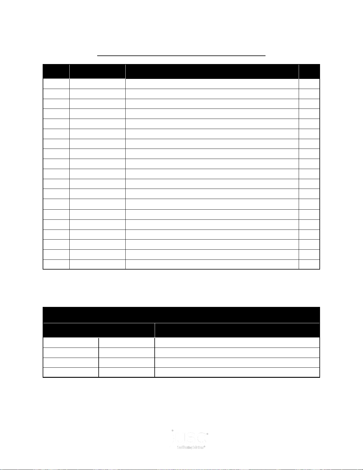
PORTABLE LPV TREATER
17 FT INLET CONVEYOR ASSEMBLY (17-13-0028)
Item # Part #
1 05-06-0111
2 05-06-0112 CVR SPLICE INLET RND CNVR 8IN 2
3 06-01-0006 BOLT, .250-20 X .75 UNC ZP GRADE 5 4
4 06-01-0261 BOLT FLG .3125-18 X .500 ZP GR5 8
5 06-03-0001 NUT,LOCK, .250-20 ZP G5 NYLON INSERT 4
6 06-05-0001 WASHER, FLAT .250 8
7 102F37 FLR MNT CNVR BRKT 2
8 103B89 PLT REAR CVR 1
9 1053D5 PLT LG INLET DEFLECTOR 1
10 1058E0 PLT RH INLET CVR PORT 1
11 1058E1 PLT LH INLET CVR PORT 1
12 11-02-0136 BELT CNVR CLTS TS1217 1
13 13-08-0532 ASSY INLET SECT TS25 1
14 13-08-0540 ASSY LG INLET HOPPER TS25 1
15 13-08-0653 KIT DRIVE 5HP DD TS25 1
16 13-08-0668 ASSY INLET EXT CLEAN OUT 1
17 13-08-0705 ASSY ADJ SPOUT TS CNVRS 1
18 13-08-0737 ASSY HEAD SECT TS2517 LPV-PORT 1
19 SEE TABLE 1 CONVEYOR MOTOR 1
CVR SPLICE RND CNVR 8IN 1
Description Qty
TABLE 1
Conveyor Part # Motor Part # Conveyor Description
17-13-0028 01-01-0107 INLET TREATER CONVEYOR 17FT 230V 1PH
17-13-0029 01-01-0151 INLET TREATER CONVEYOR 17FT 230V 3PH
17-13-0030 01-01-0209 INLET TREATER CONVEYOR 17FT 460V 3PH
17-13-0031 01-01-0143 INLET TREATER CONVEYOR 17FT 575V 3PH
Page 67
Page 68
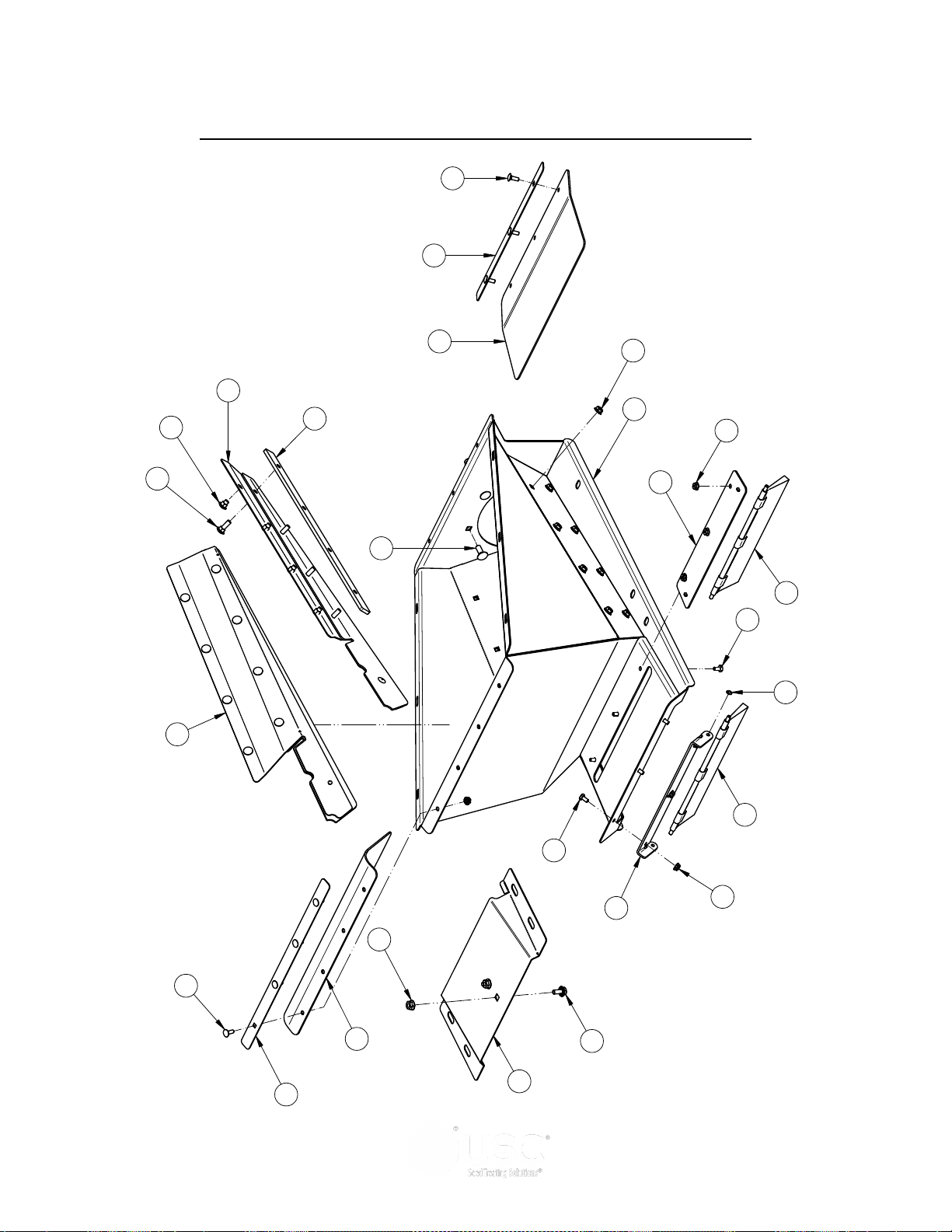
PORTABLE LPV TREATER
DRAWN
CHECKED
ENG APPR
NAME
davidw
DATE
UNLESS OTHERWISE SPECIFIED DIMENSIONS ARE IN INCHES:
TOLERANCES:
DECIMALS ANGLES
.XX=±.06
.XXX=±.031
±1°
DO NOT SCALE DRAWING
THIS MATERIAL IS THE CONFIDENTIAL AND PROPRIETARY PROPERTY OF
USC, LLC. AND SHALL NOT BE USED WITHOUT PERMISSION.
02/23/17
7
8
3
10
4
11
2
22
23
13
15
12
1
14
20
21
9
6
16
17
18
19
5
Item Number Document Number REV Quantity Title
1 05-08-0536 A 1 WDMT PIVOT BRSH PLT TS25
2 05-08-0698 A 1 WDMT INLET HOP TS25 LPV PORT
3 06-01-0004 A 6 BOLT, .250-20 X .500 UNC ZP GRADE 5
4 06-01-0115 A 2 BOLT CRG .375-16 X 1.00 ZP GR5
5 06-01-0122 A 7 BOLT, CARRIAGE, .250-20x.75 G5 ZP
6 06-01-0124 A 2 BOLT FLG .375-16 X .750 ZP GR5
7 06-01-0129 A 8 BOLT CRG .313-18 X .50 ZP GR5
8 06-01-0223 A 8 BOLT CRG .313-18 X 1.00 ZP GR5
9 06-02-0100 A 2 PUSH NUT SS .250 UNTHREADED
10 06-03-0013 A 13 NUT,LOCK, FLG .250-20 ZP SERRATTED
11 06-03-0014 A 4 NUT LOCK FLG .375-16 ZP GR5
12 06-03-0019 A 16 NUT LOCK FLG .3125-18 ZP GR5
13 103D17 A 2 PLT SKIRT SPACER
14 10472A B 1 EAR BRUSH MNT
15 105608 A 1 COVER CLN\OUT
16 105770 A 1 STRAP SEAL MNT
17 105771 A 1 INLET SEAL RBBR
18 105772 A 1 STRAP SEAL MNT
19 105773 A 1 INLET SEAL RBBR
20 13-05-0478 B 1 ASSY BRUSH W\CLIPS 11.25
21 13-05-0479 B 1 ASSY BRUSH W\CLIPS 11.88
22 13-05-0582 B 1 ASSY SKIRT RH TS25
23 13-05-0583 B 1 ASSY SKIRT RIGID TS25
5
3
10
OUTLET CONVEYOR INLET HOPPER ASSEMBLY (13-08-0736)
Page 68
Page 69

PORTABLE LPV TREATER
OUTLET CONVEYOR INLET HOPPER ASSEMBLY (13-08-0736)
Item # Part #
1 05-08-0536
2 05-08-0698 WDMT INLET HOP TS25 LPV PORT 1
3 06-01-0004 BOLT, .250-20 X .500 UNC ZP GRADE 5 6
4 06-01-0115 BOLT CRG .375-16 X 1.00 ZP GR5 2
5 06-01-0122 BOLT, CARRIAGE, .250-20x.75 G5 ZP 7
6 06-01-0124 BOLT FLG .375-16 X .750 ZP GR5 2
7 06-01-0129 BOLT CRG .313-18 X .50 ZP GR5 8
8 06-01-0223 BOLT CRG .313-18 X 1.00 ZP GR5 8
9 06-02-0100 PUSH NUT SS .250 UNTHREADED 2
10 06-03-0013 NUT,LOCK, FLG .250-20 ZP SERRATTED 13
11 06-03-0014 NUT LOCK FLG .375-16 ZP GR5 4
12 06-03-0019 NUT LOCK FLG .3125-18 ZP GR5 16
13 103D17 PLT SKIRT SPACER 2
14 10472A EAR BRUSH MNT 1
15 105608 COVER CLN\OUT 1
16 105770 STRAP SEAL MNT 1
17 105771 INLET SEAL RBBR 1
18 105772 STRAP SEAL MNT 1
19 105773 INLET SEAL RBBR 1
20 13-05-0478 ASSY BRUSH W\CLIPS 11.25 1
21 13-05-0479 ASSY BRUSH W\CLIPS 11.88 1
22 13-05-0582 ASSY SKIRT RH TS25 1
23 13-05-0583 ASSY SKIRT RIGID TS25 1
WDMT PIVOT BRSH PLT TS25 1
Description Qty
Page 69
Page 70
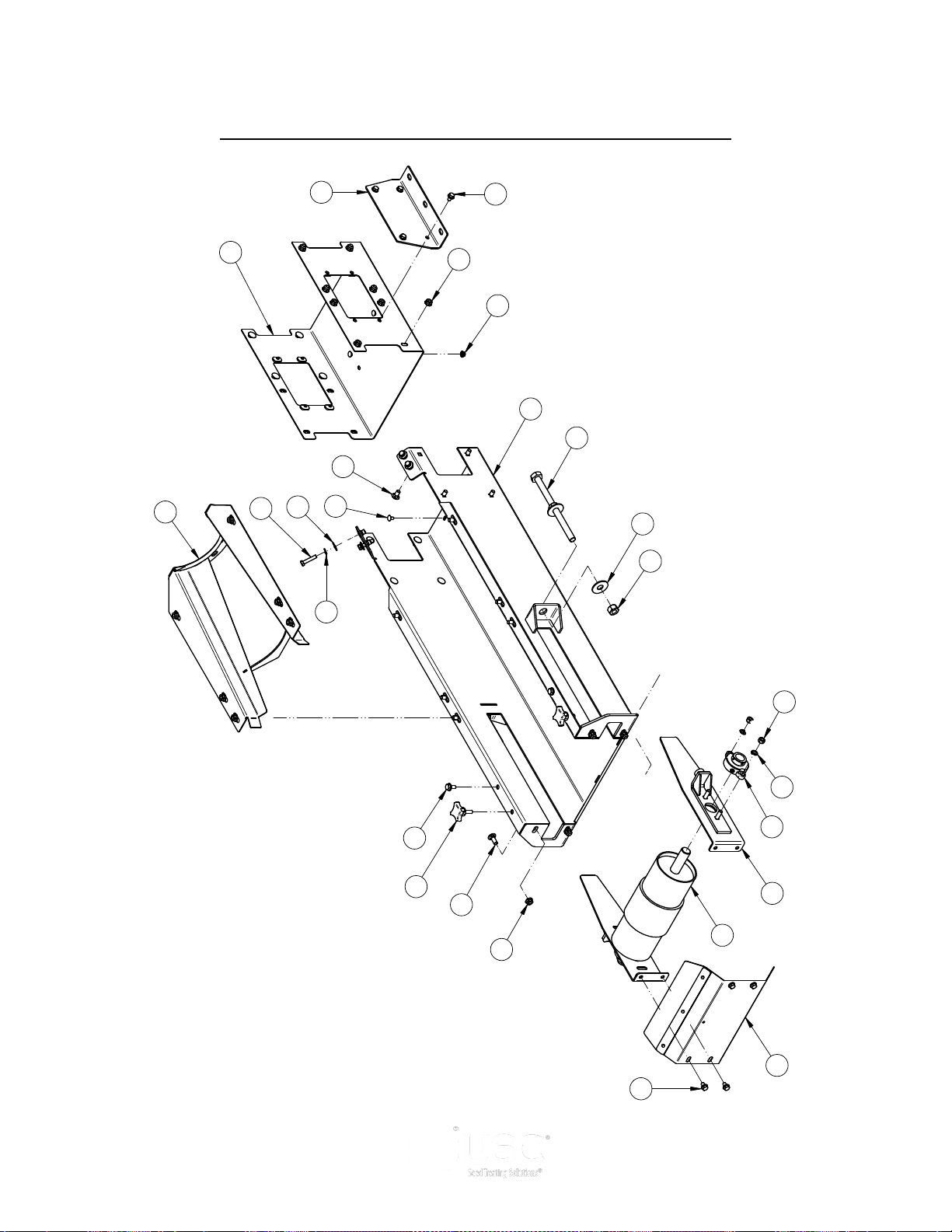
DRAWN
CHECKED
ENG APPR
NAME
davidw
DATE
11/10/14
TITLE
SIZE
D
File Name:13-08-0710B = Inlet .dft
UNLESS OTHERWISE SPECIFIED DIMENSIONS ARE IN INCHES:
TOLERANCES:
DECIMALS ANGLES
.XX=±.06
.XXX=±.031
±1°
DO NOT SCALE DRAWING
THIS MATERIAL IS THE CONFIDENTIAL AND PROPRIETARY PROPERTY OF
USC, LLC. AND SHALL NOT BE USED WITHOUT PERMISSION.
ASSY INLET SECT TS25 PORT
Printed 03/06/17 at 13:24
11
10
16
13
7
8
9
14
17
19
12
15
21
22
1
2
5
4
23
24
3
20
18
Item Number Document Number Quantity Title
1 01-03-0042 2 BRG FLG MNT 1.000ID 2BOLT ECNTRC
2 01-08-0108 1 PULLEY TAIL W-LAGGING
3 05-08-0404 2 WDMT TAKE-UP PLT RND CNVR
4 05-08-0419 1 WDMT SPLICE 12IN
5 05-08-0569 1 WDMT TAIL TRANS TS25
6 05-10-4339 2 PLT STOP MOUNT
7 06-01-0013 4 BOLT, .312-18 UNC ZP GRADE 5; 1.50" LG
8 06-01-0115 4 BOLT CRG .375-16 X 1.00 ZP GR5
9 06-01-0124 2 BOLT FLG .375-16 X .750 ZP GR5
10 06-01-0150 4 BOLT, CARRIAGE, .250-20x.50 G5 ZP
11 06-01-0153 22 BOLT CRG .375-16X.750 ZP SHORT NECK
12 06-01-0249 2 BOLT .625-11 X 9.00 ZP GR5 FTH
13 06-01-0261 12 BOLT FLG .3125-18 X .500 ZP GR5
14 06-02-0003 4 NUT FULL .375-16 ZP GR5
15 06-02-0005 4 NUT, .625-11 UNC ZP GRADE 5
16 06-03-0013 4 NUT,LOCK, FLG .250-20 ZP SERRATTED
17 06-03-0014 28 NUT LOCK FLG .375-16 ZP GR5
18 06-04-0002 4 WSHR LOCK SPLT .313 ZP
19 06-04-0003 4 WSHR LOCK SPLT .375 ZP
20 06-05-0003 4 WSHR FLAT .313 ZP
21 06-05-0006 4 WASHER, .625 FLAT ZP
22 06-09-0066 2 KNOB .375 -16 X 1. 4 LUG PLASTIC
23 13-05-0585 1 ASSY INLET W/RIVETNUTS TS25 PORT
24 13-08-0722 1 ASSY BAFFLE W/SEAL TS25
6
17
13
PORTABLE LPV TREATER
OUTLET CONVEYOR INLET END ASSEMBLY (13-08-0710)
Page 70
Page 71

PORTABLE LPV TREATER
OUTLET CONVEYOR INLET END ASSEMBLY (13-08-0710)
Item # Part #
1 01-03-0042
2 01-08-0108 PULLEY TAIL W-LAGGING 1
3 05-08-0404 WDMT TAKE-UP PLT RND CNVR 2
4 05-08-0419 WDMT SPLICE 12IN 1
5 05-08-0569 WDMT TAIL TRANS TS25 1
6 05-10-4339 PLT STOP MOUNT 2
7 06-01-0013 BOLT, .312-18 UNC ZP GRADE 5; 1.50" LG 4
8 06-01-0115 BOLT CRG .375-16 X 1.00 ZP GR5 4
9 06-01-0124 BOLT FLG .375-16 X .750 ZP GR5 2
10 06-01-0150 BOLT, CARRIAGE, .250-20x.50 G5 ZP 4
11 06-01-0153 BOLT CRG .375-16X.750 ZP SHORT NECK 22
12 06-01-0249 BOLT .625-11 X 9.00 ZP GR5 FTH 2
13 06-01-0261 BOLT FLG .3125-18 X .500 ZP GR5 12
14 06-02-0003 NUT FULL .375-16 ZP GR5 4
15 06-02-0005 NUT, .625-11 UNC ZP GRADE 5 4
16 06-03-0013 NUT,LOCK, FLG .250-20 ZP SERRATED 4
17 06-03-0014 NUT LOCK FLG .375-16 ZP GR5 28
18 06-04-0002 WSHR LOCK SPLT .313 ZP 4
19 06-04-0003 WSHR LOCK SPLT .375 ZP 4
20 06-05-0003 WSHR FLAT .313 ZP 4
21 06-05-0006 WASHER, .625 FLAT ZP 4
22 06-09-0066 KNOB .375 -16 X 1. 4 LUG PLASTIC 2
BRG FLG MNT 1.000ID 2BOLT ECNTRC 2
Description Qty
23 13-05-0585 ASSY INLET W/RIVETNUTS TS25 PORT 1
24 13-08-0722 ASSY BAFFLE W/SEAL TS25 1
Page 71
Page 72
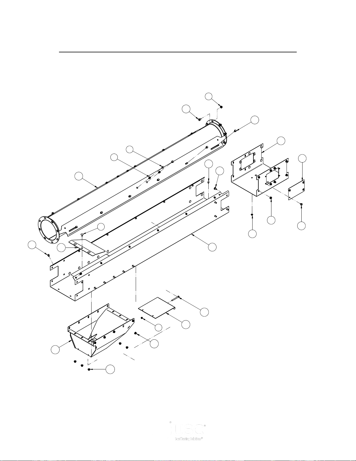
PORTABLE LPV TREATER
4
7
6
5
8
1
2
9
Item Number Document Number REV Quantity Title
1 05-08-0419 A 1 WDMT SPLICE 12IN
2 05-08-0461 B 1 WDMT TUBE 8.00IN X 84.86IN
3 05-08-0610 A 1 WDMT CLEAN OUT
4 05-10-4576 A 1 FRAME INLET SEC CLN/OUT TS25
5 06-01-0124 A 8 BOLT FLG .375-16 X .750 ZP GR5
6 06-01-0138 A 16 BOLT, FLG .3125-18 UNC ZP GRADE 5; 3/4" LG
7 06-01-0150 A 4 BOLT, CARRIAGE, .250-20x.50 G5 ZP
8 06-01-0153 A 32 BOLT CRG .375-16X.750 ZP SHORT NECK
9 06-01-0261 A 8 BOLT FLG .3125-18 X .500 ZP GR5
10 06-01-0311 A 1 BOLT .313-18 X 3.25 ZP GR5
11 06-02-0092 A 16 RIVETNUT .312-18 ZP
12 06-03-0002 A 1 NUT NYL LOCK .313-18 ZP GR5
13 06-03-0013 A 4 NUT,LOCK, FLG .250-20 ZP SERRATTED
14 06-03-0014 A 40 NUT LOCK FLG .375-16 ZP GR5
15 103B9A A 2 PLT SPLICE COVER
16 1050CF A 1 PLT DOOR CLEAN OUT
17 1050E8 A 1 PLT BELT GUIDE
12
14
15
16
12
7
18
17
13
11
4
8
14
14
12
OUTLET CONVEYOR CLEAN OUT EXTENSION ASSEMBLY (13-08-0707)
Page 72
Page 73

PORTABLE LPV TREATER
OULLET CONVEYOR CLEAN OUT EXTENSION ASSEMBLY (13-08-0707)
Item # Part #
1 05-08-0419
2 05-08-0461 WDMT TUBE 8.00IN X 84.86IN 1
3 05-08-0610 WDMT CLEAN OUT 1
4 05-10-4576 FRAME INLET SEC CLN/OUT TS25 1
5 06-01-0124 BOLT FLG .375-16 X .750 ZP GR5 8
6 06-01-0138 BOLT, FLG .3125-18 UNC ZP GRADE 5; 3/4" LG 16
7 06-01-0150 BOLT, CARRIAGE, .250-20x.50 G5 ZP 4
8 06-01-0153 BOLT CRG .375-16X.750 ZP SHORT NECK 32
9 06-01-0261 BOLT FLG .3125-18 X .500 ZP GR5 8
10 06-01-0311 BOLT .313-18 X 3.25 ZP GR5 1
11 06-02-0092 RIVETNUT .312-18 ZP 16
12 06-03-0002 NUT NYL LOCK .313-18 ZP GR5 1
13 06-03-0013 NUT,LOCK, FLG .250-20 ZP SERRATTED 4
14 06-03-0014 NUT LOCK FLG .375-16 ZP GR5 40
15 103B9A PLT SPLICE COVER 2
16 1050CF PLT DOOR CLEAN OUT 1
17 1050E8 PLT BELT GUIDE 1
WDMT SPLICE 12IN 1
Description Qty
Page 73
Page 74
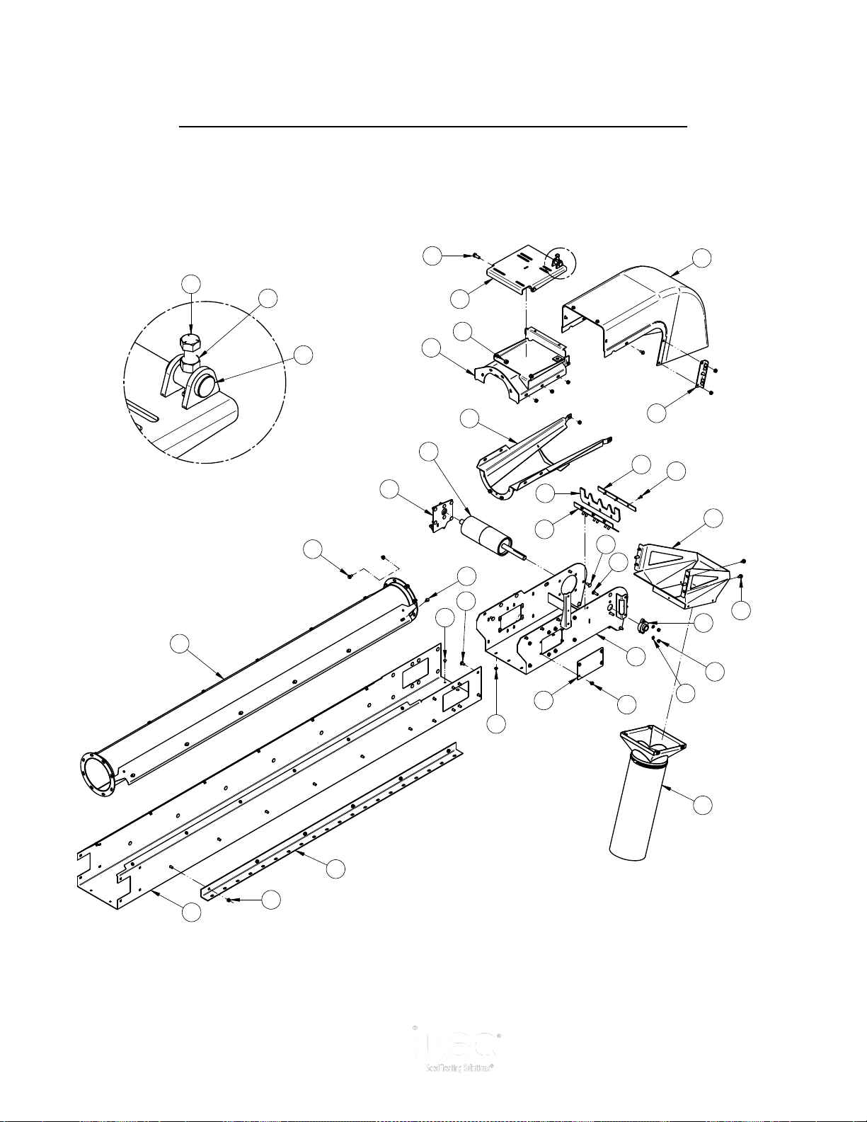
PORTABLE LPV TREATER
A
DETAIL A
18
25
21
19
22
26
27
11
33
28
1
2
6
34
29
4
17
15
13
12
20
23
24
3
30
35
7
5
8
9
32
Item Number Docume nt Number REV Quantity Title
1 01-03-0042 A 1 BRG FLG MNT 1 .000ID 2BOLT ECNTRC
2 01-08-0109 A 1 PULL EY HEAD VULC TS2500
3 05-06-0131 A 1 COVER HD TS25 DD
4 05-08-0416 B 1 WDMT TUBE 8 .00IN X 95.14IN
5 05-08-0549 A 1 WDMT MTR MNT PLT LG
6 05-08-0564 A 1 WDMT HD TRANS TS25
7 05-08-0565 A 1 WDMT HD CVR T S25
8 05-08-0566 A 1 WDMT DSCHG HD TS25
9 05-08-0567 A 1 WDMT DSCHG HD SPOUT TS25
10 05-08-0568 A 2 WDMT DSCHG HD MNT PLT
11 05-10-4028 A 2 TRANSPORT STOP PLT EXT MNT
12 06-01-0080 A 2 BOLT .500-13 X 1 .25 ZP GR5
13 06-01-0115 A 4 BOLT CRG .375-16 X 1.00 ZP GR5
14 06-01-0122 A 3 BOLT, CARRI AGE, .250-20x.75 G5 ZP
15 06-01-0124 A 10 BOLT FLG .375-16 X .750 ZP GR5
16 06-01-0127 A 2 BOLT CRG .375-16 X 1.25 ZP GR5
17 06-01-0138 A 18 BOLT, FLG .3125-18 UNC ZP GRADE 5; 3/4" LG
18 06-01-0150 A 6 BOLT, CAR RIAGE, .250-20x.50 G5 ZP
19 06-01-0153 A 42 BOLT CRG .375-16X.750 ZP SHORT NECK
20 06-01-0157 A 1 BOLT, . 500-13 X 4" UNC ZP GRADE 5 fth
21 06-01-0261 A 8 BOLT FLG . 3125-18 X .500 ZP GR5
22 06-02-0003 A 2 NUT FULL .375-16 ZP GR5
23 06-02-0004 A 1 NUT FULL .500-13 ZP GR5
24 06-03-0004 A 2 NUT NYL LOCK .500-13 ZP GR5
25 06-03-0013 A 9 NUT,LOCK, FLG .250-20 ZP SERRATTED
26 06-03-0014 A 52 NUT LOCK FLG .375-16 ZP GR5
27 06-04-0003 A 2 WSHR LOCK SPLT .375 ZP
28 103B39 A 1 PLT SCRAPER HLDR 12IN CNVR
29 103B9A A 2 PLT SPLICE COVER
30 10414A A 1 PIN MTR PIVOT
31 104259 A 1 RBBR SCRAPER 12IN FILL
32 104C11 A 1 PLT BAFFLE MNT
33 13-05-0227B B 1 ASSY 8ID FLEX SPOUT S2000
34 13-05-0508 A 1 AS SY FRAME HD TS25 DD W/RIVETNUTS
35 13-08-0564 A 1 ASS Y TRACKING PLT HD
NOTES:
GREASE ZERK IS TO BE POINTED DOWN WHEN ASSEMBLED.
PULLEY IS TO BE OFFSET WHEN INSTALLED IN ORDER TO ASSEMBLE LOCKING COLLAR.
POSITION RUBBER SCRAPER TO HIGHEST SETTING WITHOUT CONTACTING BELT.
HEAD COVER IS TO BE INSIDE SPOUT WDMT WHEN ASSEMBLED.
MOTOR MOUNT PLATE MUST PIVOT FREELY AFTER INSTALLATION.
1.
2.
3.
4.
5.
14
16
10
31
15
OUTLET CONVEYOR HEAD SECTION ASSEMBLY (13-08-0652)
Page 74
Page 75

PORTABLE LPV TREATER
OUTLET CONVEYOR HEAD SECTION ASSEMBLY (13-08-0652)
Item # Part #
1 01-03-0042
2 01-08-0109 PULLEY HEAD VULC TS2500 1
3 05-06-0131 COVER HD TS25 DD 1
4 05-08-0416 WDMT TUBE 8.00IN X 95.14IN 1
5 05-08-0549 WDMT MTR MNT PLT LG 1
6 05-08-0564 WDMT HD TRANS TS25 1
7 05-08-0565 WDMT HD CVR TS25 1
8 05-08-0566 WDMT DSCHG HD TS25 1
9 05-08-0567 WDMT DSCHG HD SPOUT TS25 1
10 05-08-0568 WDMT DSCHG HD MNT PLT 2
11 05-10-4028 TRANSPORT STOP PLT EXT MNT 2
12 06-01-0080 BOLT .500-13 X 1.25 ZP GR5 2
13 06-01-0115 BOLT CRG .375-16 X 1.00 ZP GR5 4
14 06-01-0122 BOLT, CARRIAGE, .250-20x.75 G5 ZP 3
15 06-01-0124 BOLT FLG .375-16 X .750 ZP GR5 10
16 06-01-0127 BOLT CRG .375-16 X 1.25 ZP GR5 2
17 06-01-0138 BOLT, FLG .3125-18 UNC ZP GRADE 5; 3/4" LG 18
18 06-01-0150 BOLT, CARRIAGE, .250-20x.50 G5 ZP 6
19 06-01-0153 BOLT CRG .375-16X.750 ZP SHORT NECK 42
20 06-01-0157 BOLT, .500-13 X 4" UNC ZP GRADE 5 fth 1
21 06-01-0261 BOLT FLG .3125-18 X .500 ZP GR5 8
22 06-02-0003 NUT FULL .375-16 ZP GR5 2
23 06-02-0004 NUT FULL .500-13 ZP GR5 1
24 06-03-0004 NUT NYL LOCK .500-13 ZP GR5 2
25 06-03-0013 NUT,LOCK, FLG .250-20 ZP SERRATTED 9
26 06-03-0014 NUT LOCK FLG .375-16 ZP GR5 52
27 06-04-0003 WSHR LOCK SPLT .375 ZP 2
28 103B39 PLT SCRAPER HLDR 12IN CNVR 1
29 103B9A PLT SPLICE COVER 2
30 10414A PIN MTR PIVOT 1
31 104259 RBBR SCRAPER 12IN FILL 1
32 104C11 PLT BAFFLE MNT 1
33 13-05-0227 ASSY 8ID FLEX SPOUT S2000 1
34 13-05-0508 ASSY FRAME HD TS25 DD W/RIVETNUTS 1
35 13-08-0564 ASSY TRACKING PLT HD 1
BRG FLG MNT 1.000ID 2BOLT ECNTRC 1
Description Qty
Page 75
Page 76
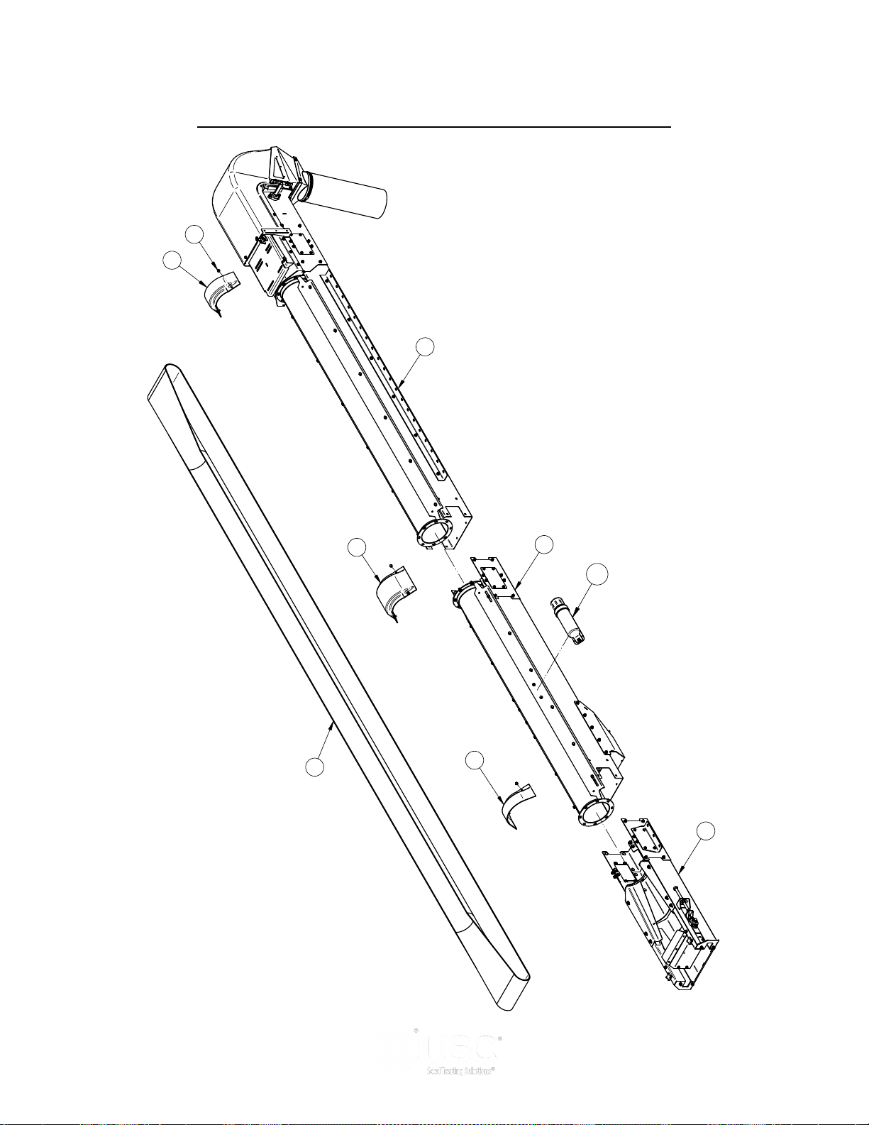
PORTABLE LPV TREATER
DRAWN
CHECKED
ENG APPR
NAME
davidw
DATE
TITLE
SIZE
D
DWG NO
File Name:13-08-0706B = 20FT Cnvr Base.dft
SHEET 1 OF 2
UNLESS OTHERWISE SPECIFIED DIMENSIONS ARE IN INCHES:
TOLERANCES:
DECIMALS ANGLES
.XX=±.06
.XXX=±.031
±1°
DO NOT SCALE DRAWING
U S C, L L C.
Sabetha, Kansas 66534 USA
THIS MATERIAL IS THE CONFIDENTIAL AND PROPRIETARY PROPERTY OF
USC, LLC. AND SHALL NOT BE USED WITHOUT PERMISSION.
13-08-0706
ASSY TS25 20FT BASE PORT
Printed 03/06/17 at 14:28
B
Rev
11/10/14
3
1
2
10
11
9
6
Item Number Document Number REV Quantity Title
1 05-06-0111 A 1 CVR SPLICE RND CNVR 8IN
2 05-06-0112 A 2 CVR SPLICE INLET RND CNVR 8IN
3 06-01-0261 A 8 BOLT FLG .3125-18 X .500 ZP GR5
4* 09-01-0178 A 2 LBL ATWK TS2520
5* 09-02-0016 A 1 LBL ATWRK ATT BELT ALIGN
6 11-02-0139 A 1 BELT CNVR CLTS TS3520
7 13-05-0332 A 1 ASSY MANUAL TUBE MT
8* 13-05-0353 A 1 DECAL PKG TS CNVRS
9 13-08-0652 A 1 ASSY HEAD SECT TS25 DD
10 13-08-0707 A 1 ASSY INLET CLN/OUT TS25 PORT
11 13-08-0710 B 1 ASSY INLET SECT TS25 PORT
7
2
20 FT OUTLET CONVEYOR BASE ASSEMBLY (13-08-0706)
Page 76
Page 77

PORTABLE LPV TREATER
20 FT OUTLET CONVEYOR BASE ASSEMBLY (13-08-0706)
Item # Part #
1 05-06-0111
2 05-06-0112 CVR SPLICE INLET RND CNVR 8IN 2
3 06-01-0261 BOLT FLG .3125-18 X .500 ZP GR5 8
4 09-01-0178 LBL ATWK TS2520 2
5 09-02-0016 LBL ATWRK ATT BELT ALIGN 1
6 11-02-0139 BELT CNVR CLTS TS3520 1
7 13-05-0332 ASSY MANUAL TUBE MT 1
8 13-05-0353 DECAL PKG TS CNVRS 1
9 13-08-0652 ASSY HEAD SECT TS25 DD 1
10 13-08-0707 ASSY INLET CLN/OUT TS25 PORT 1
11 13-08-0710 ASSY INLET SECT TS25 PORT 1
CVR SPLICE RND CNVR 8IN 1
Description Qty
NOTE: Items 4,5 and 8 not shown on drawing.
Page 77
Page 78
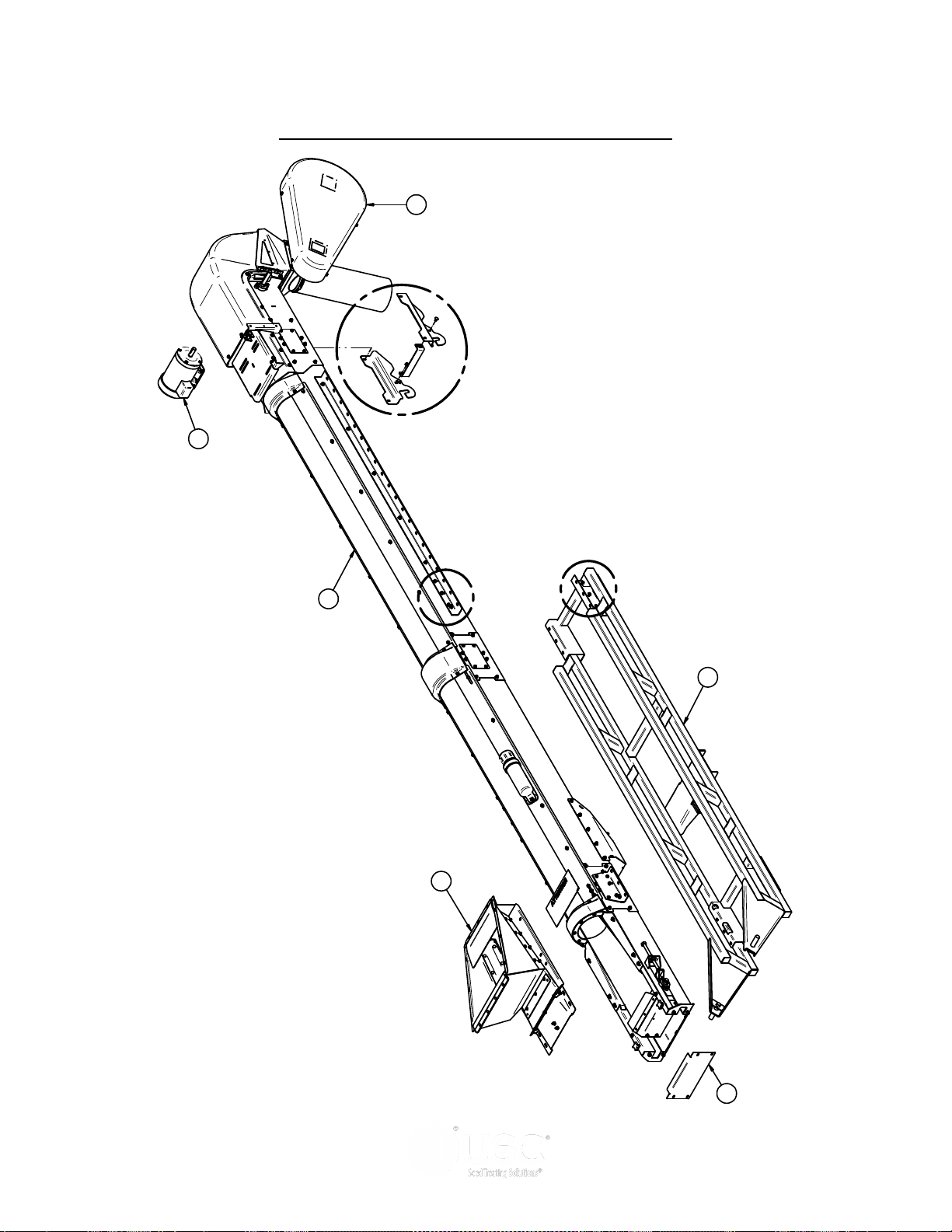
PORTABLE LPV TREATER
SHEET 1 OF 2
FILENAME: 17-13-0024A3 = 20FT Outlet Cnvr
TITLE: TS25 CNVR 20FT 5HP 230V 1PH PORT
TOLERANCES
FRACTIONS: +/- 1/8"
DECIMALS: X.XX +/- .06", X.XXX +/-.031
ANGLES: +/- 1°
THIS MATERIAL IS THE
CONFIDENTIAL AND
PROPRIETARY PROPERTY OF
USC, LLC. AND SHALL NOT BE
USED WITHOUT PERMISSION.
05/31/17 at 17:19
REV: A DWG#: 17-13-0024
1
5
A
B
C
12
10
11
9
20 FT OUTLET CONVEYOR TOP ASSEMBLY
Page 78
Page 79
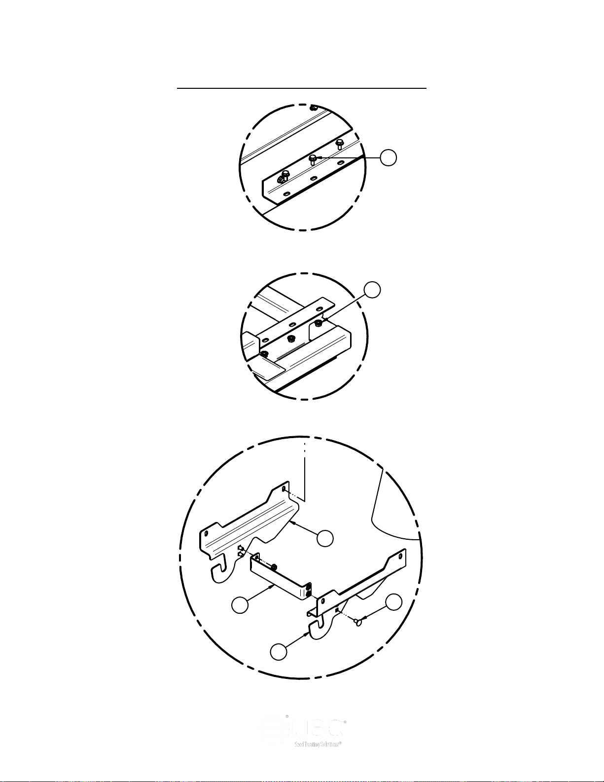
REV DESCRIPTION DATE BY
002
DELETE 13-08-0540, 1055AE, 06-06-0052.
ADD 13-08-0736
003 REV 13-08-0706 FROM A TO B 4/26/2017 LGH
004 ADD 1058EF, 1058FE, 1058FF, 06-01-0153 5/30/2017 LGH
Item # Part # Rev Title Qty
1 05-03-1689 A WDMT PORT OUTLET CNVR SUPP FRM 1
2 06-01-0124 A BOLT FLG .375-16 X .750 ZP GR5 12
3 06-01-0153 A BOLT CRG .375-16X.750 ZP SHORT NECK 4
4 06-03-0014 A NUT LOCK FLG .375-16 ZP GR5 16
5 103B89 A PLT REAR CVR 1
6 1058EF A STRAP TIE 1
7 1058FE A PLT CNVR LOCK RH 1
8 1058FF A PLT CNVR LOCK LH 1
9 13-08-0653 A KIT DRIVE 5HP DD TS25 1
10 13-08-0706 B ASSY TS25 20FT BASE PORT 1
11 13-08-0736 A ASSY INLET HOP TS25 LPV PORT 1
12 SEE TABLE 1 CONVEYOR DRIVE MOTOR 1
DETAIL C
3
6
7
DETAIL B
4
DETAIL A
2
8
PORTABLE LPV TREATER
20 FT OUTLET CONVEYOR TOP ASSEMBLY
Page 79
Page 80
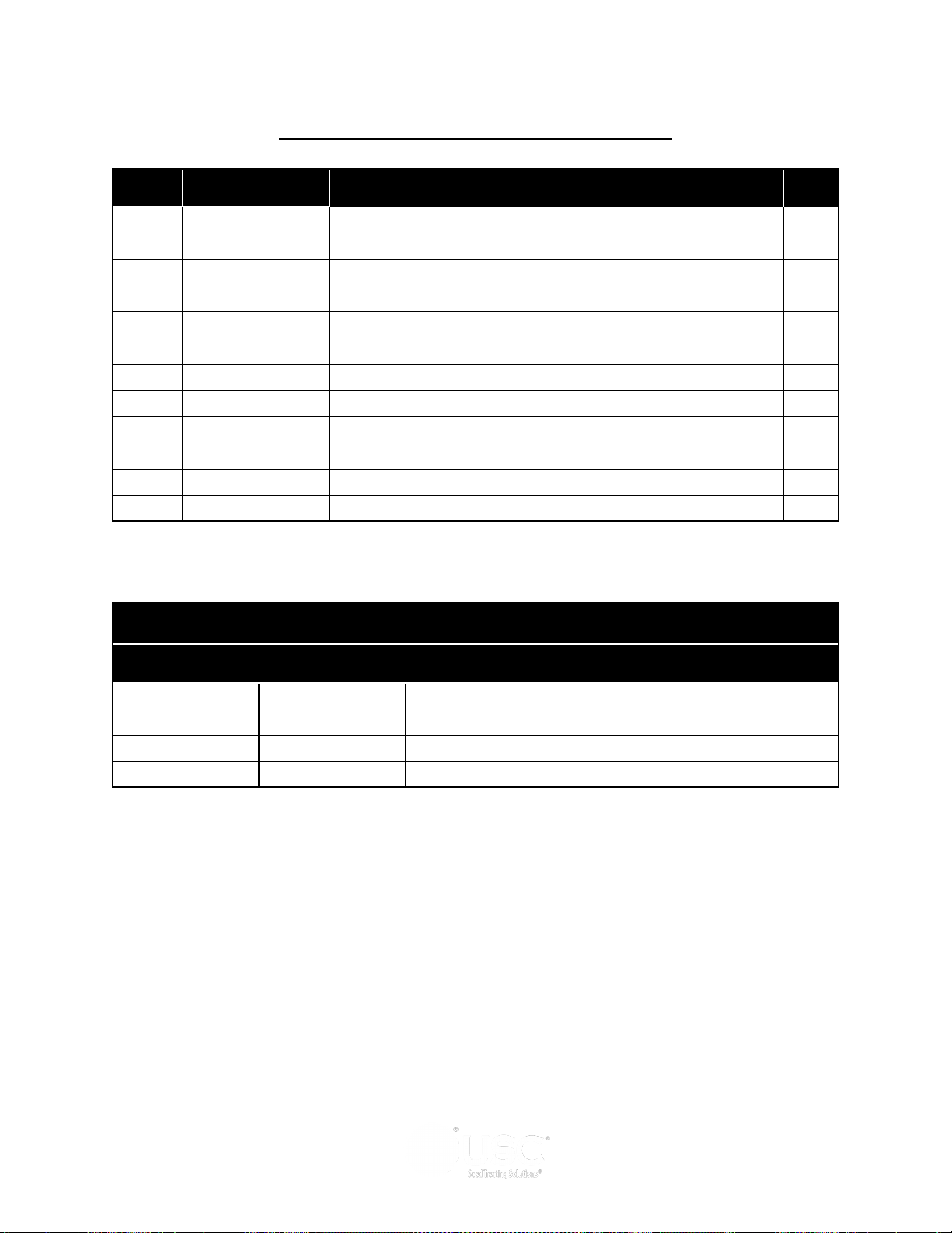
PORTABLE LPV TREATER
20 FT OUTLET CONVEYOR TOP ASSEMBLY
Item # Part #
1 05-03-1689
2 06-01-0124 BOLT FLG .375-16 X .750 ZP GR5 12
3 06-01-0153 BOLT CRG .375-16X.750 ZP SHORT NECK 4
4 06-03-0014 NUT LOCK FLG .375-16 ZP GR5 16
5 103B89 PLT REAR CVR 1
6 1058EF STRAP TIE 1
7 1058FE PLT CNVR LOCK RH 1
8 1058FF PLT CNVR LOCK LH 1
9 13-08-0653 KIT DRIVE 5HP DD TS25 1
10 13-08-0706 ASSY TS25 20FT BASE PORT 1
11 13-08-0736 ASSY INLET HOP TS25 LPV PORT 1
12 SEE TABLE 1 CONVEYOR DRIVE MOTOR 1
WDMT PORT OUTLET CNVR SUPP FRM 1
Description Qty
TABLE 1
Conveyor Part # Motor Part # Conveyor Description
17-13-0024 01-01-0107 OUTLET TREATER CONVEYOR 20FT 230V 1PH
17-13-0025 01-01-0151 OUTLET TREATER CONVEYOR 20FT 230V 3PH
17-13-0026 01-01-0209 OUTLET TREATER CONVEYOR 20FT 460V 3PH
17-13-0027 01-01-0143 OUTLET TREATER CONVEYOR 20FT 575V 3PH
Page 80
Page 81
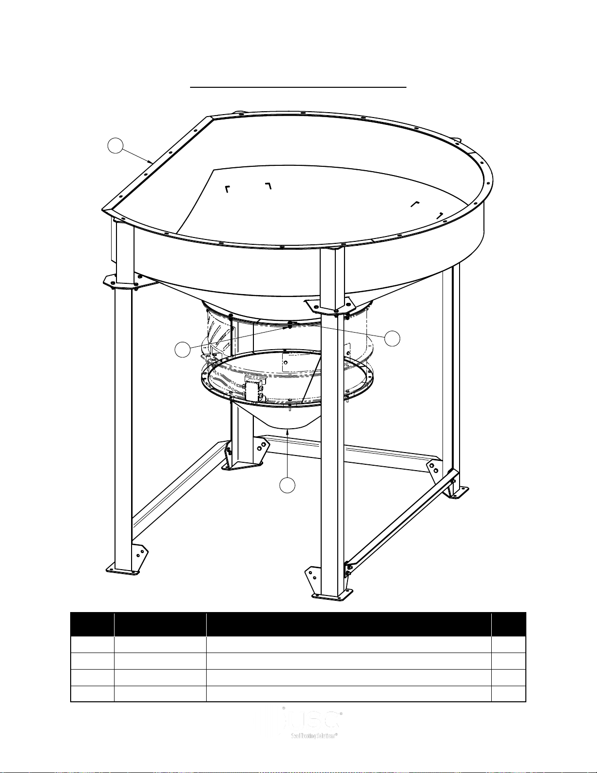
PORTABLE LPV TREATER
2
1
4
3
FILL HOPPER ASSEMBLY (13-04-0127)
Item # Part #
1 05-03-0282
2 05-07-0080 HOPP S2000 PORT FOR SMW 1
3 06-01-0189 BOLT FLG .375-16 X 1.250 ZP GR5 8
4 06-03-0014 NUT LOCK FLG .375-16 ZP GR5 8
WDMT HOPP SMW DSCHG 1
Description Qty
Page 81
Page 82
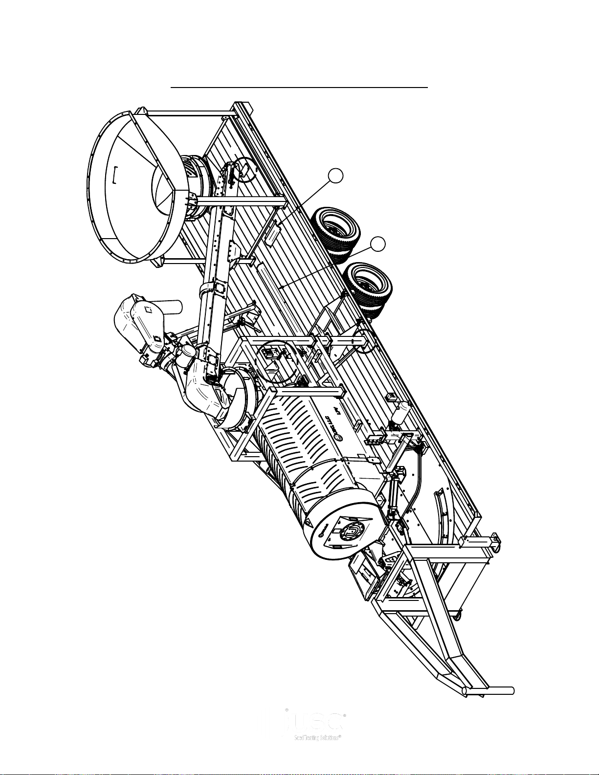
PORTABLE LPV TREATER
SHEET 1 OF 2
FILENAME: 13-10-0055 = LPV Port Hdwr Kit
TITLE: KIT HDWR LPV PORT TRTR
TOLERANCES
FRACTIONS: +/- 1/8"
DECIMALS: X.XX +/- .06", X.XXX +/-.031
ANGLES: +/- 1°
THIS MATERIAL IS THE
CONFIDENTIAL AND
PROPRIETARY PROPERTY OF
USC, LLC. AND SHALL NOT BE
USED WITHOUT PERMISSION.
06/08/17 at 10:29
REV: A DWG#: 13-10-0055
A
B
C
2
1
LPV PORTABLE HARDWARE KIT (13-10-0055)
Page 82
Page 83
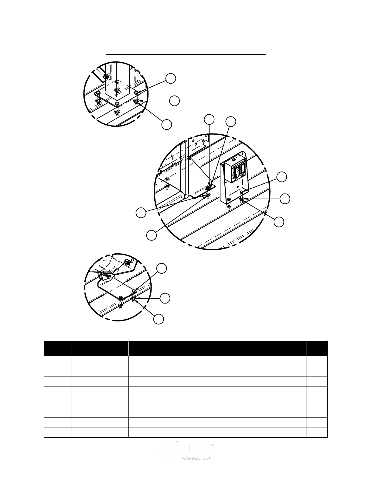
PORTABLE LPV TREATER
DETAIL B
3
7
7
5
3
7
5
DETAIL C
3
7
5
DETAIL A
4
8
6
LPV PORTABLE HARDWARE KIT (13-10-0055)
Item # Part #
Description Qty
1 05-06-0109
2 05-06-0110 ASSY CVR WIRE/HOSE GRD 1
3 06-01-0116 BOLT .375-16 X 2.75 ZP GR5 14
4 06-01-0252 BOLT .500-13 X 3.00 ZP GR5 28
5 06-03-0003 NUT NYL LOCK .375-16 ZP GR5 14
6 06-03-0004 NUT NYL LOCK .500-13 ZP GR5 28
7 06-05-0004 WSHR FLAT .375 ZP 22
8 06-05-0005 WSHR FLAT .500 ZP 28
ASSY CVR WIRE/HOSE GRD 1
Page 83
Page 84
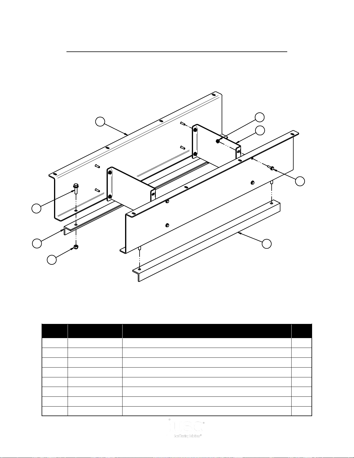
PORTABLE LPV TREATER
REVISION HISTORY
REV DESCRIPTION DATE BY
A INITIAL DRAWING 3/6/2017 martyh
001
REV 10570A, ADD 10611E, 106120,
06-01-0271, 06-03-0004
5
1
4
6
2
3
7
8
DRY ADDITIVE FEEDER FLAT MOUNTING ASSEMBLY (05-07-0933)
Item # Part #
1 06-01-0189
2 06-01-0271 BOLT FLG .500-13 X 1.750 ZP 4
3 06-03-0004 NUT NYL LOCK .500-13 ZP GR5 4
4 06-03-0014 NUT LOCK FLG .375-16 ZP GR5 8
5 10570A DAF MNT BRKT PORT 2
6 10570B DAF MNT BRKT PORT 2
7 10611E ANGL CLAMP SHORT 1
8 106120 ANGLE CLAMP LONG 1
Page 84
BOLT FLG .375-16 X 1.250 ZP GR5 8
Description Qty
Page 85
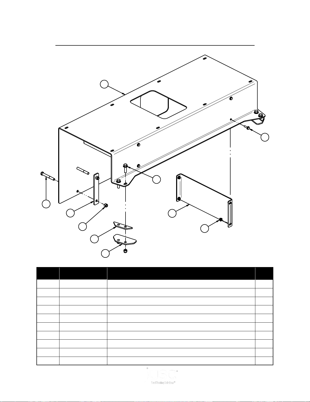
PORTABLE LPV TREATER
REV DESCRIPTION DATE BY
A INITIAL DRAWING 04/04/18 LGH
6
10
5
9
1
4
8
7
2
3
DRY ADDITIVE FEEDER ANGLE MOUNTING ASSEMBLY (05-07-1007)
Item # Part #
1 06-01-0030
2 06-01-0189 BOLT FLG .375-16 X 1.250 ZP GR5 8
3 06-01-0271 BOLT FLG .500-13 X 1.750 ZP 4
4 06-03-0004 NUT NYL LOCK .500-13 ZP GR5 10
5 06-03-0014 NUT LOCK FLG .375-16 ZP GR5 8
6 106256 PLT DAF MNT PORT 1
7 106259 PLT MNT CLMP 3
8 10625A DAF MNT BRKT PORT 2
9 10625D PLT CLMP SPACER 2
10 10625E PLT CLAMP 2
BOLT, .500-13 X 4" UNC ZP GRADE 5 6
Description Qty
Page 85
Page 86
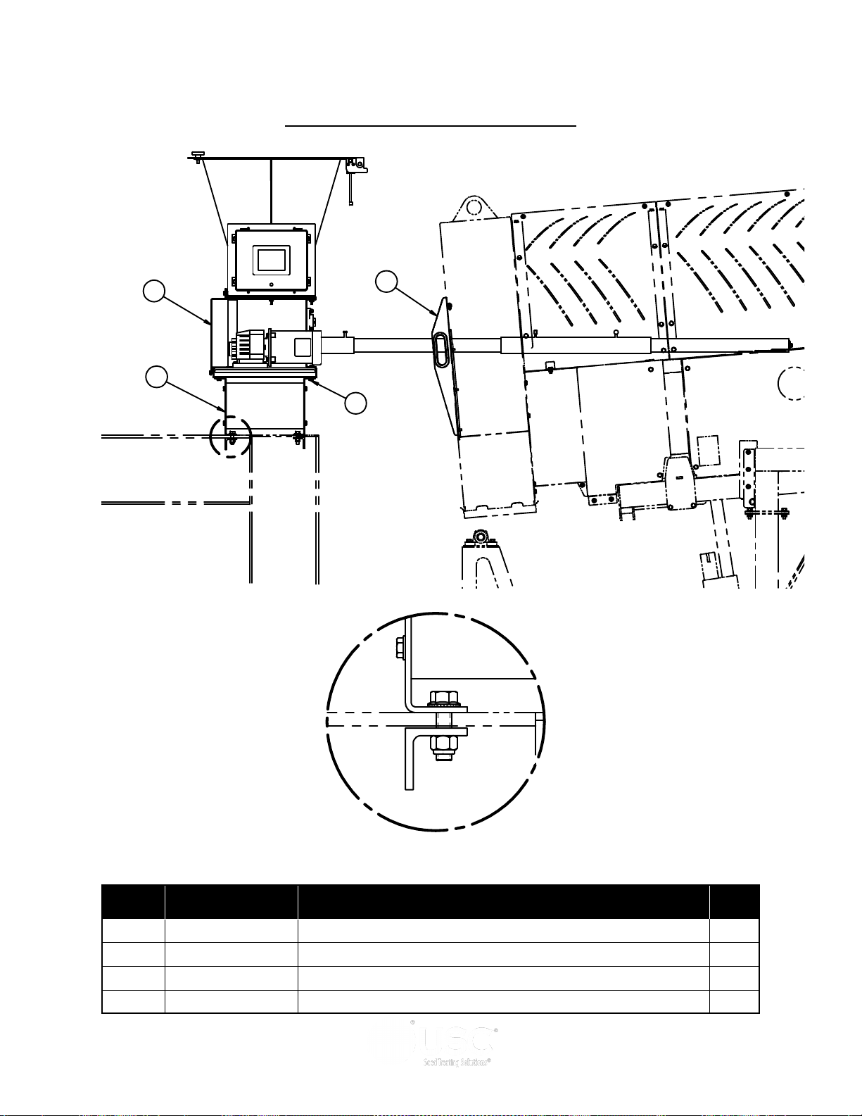
PORTABLE LPV TREATER
REVISION HISTORY
REV ECN DESCRIPTION DATE BY
MOD GOOSENECK MOUNT 3/6/2017 martyh
4
2
1
3
A
REV ECN DESCRIPTION DATE BY
MOD GOOSENECK MOUNT 3/6/2017 martyh
DETAIL A
DRY ADDITIVE FEEDER ASSEMBLY
Item # Part #
1 05-07-0924
ASSY END CHUTE DOOR DAF GALV 1
Description Qty
2 05-07-0933 ASSY DAF MNT GOOSENECK 1
3 06-01-0124 BOLT FLG .375-16 X .750 ZP GR5 4
4 13-05-0373 DAF 2046 CS 84IN REMV TUBE 1
Page 86
Page 87

PORTABLE LPV TREATER
Section
USC Limited Warranty
USC, LLC, (Manufacturer) warrants its seed treating equipment as follows:
1. Limited Warranty: Manufacturer warrants that the Products sold hereunder will be free
from defects in material and workmanship for a period of 18 months from date of shipment.
If the Products do not conform to this Limited Warranty during the warranty period, Buyer
shall notify Manufacturer in writing of the claimed defects and demonstrate to Manufacturer
satisfaction that said defects are covered by this Limited Warranty. If the defects are properly
reported to Manufacturer within the warranty period, and the defects are of such type and
nature as to be covered by this warranty, Manufacturer shall, at its expense, furnish
replacement Products or, at Manufacturer’s option, replacement parts for the defective
products. Shipping and installation of the replacement Products or replacement parts shall
be at the Buyer’s expense.
2. Other Limits: THE FOREGOING IS IN LIEU OF ALL OTHER WARRANTIES,
EXPRESSED OR IMPLIED, INCLUDING BUT NOT LIMITED TO THE IMPLIED
WARRANTIES OF MERCHANTABILITY AND FITNESS FOR A PARTICULAR PURPOSE.
Manufacturer does not warrant against damages or defects arising from improper installation
(where
installation is by persons other than Manufacturer), against defects in products or components
not manufactured by Manufacturer, or against damages resulting from such non-Manufacturer
made products or components. Manufacturer passes on to the Buyer the warranty it received
(if any) from the maker of such non-Manufacturer made products or components. This
warranty also does not apply to Products upon which repairs and / or modifications have been
effected or attempted by persons other than pursuant to written authorization by Manufacturer.
This includes any welding on equipment which could damage electrical components.
Manufacturer does not warrant against casualties or damages resulting from misuse and / or
abuse of Products, improper storage or handling, acts of nature, effects of weather, including
effects of weather due to outside storage, accidents, or damages incurred during
transportation by common carrier.
3. Exclusive Obligation: THIS WARRANTY IS EXCLUSIVE. The sole and exclusive
obligation of Manufacturer shall be to repair or replace the defective Products in the manner
and for the period provided above. Manufacturer shall not have any other obligation with
respect to the Products or any part thereof, whether based on contract, tort, strict liability or
otherwise. Under no circumstances, whether based on this Limited Warranty or otherwise,
shall Manufacturer be liable for lost profits, lost revenue, lost sales (whether direct or indirect
damages), incidental, special, punitive, indirect or consequential damages.
4. Other Statements: Manufacturer’s employees or representatives’ oral or other written
statements do not constitute warranties, shall not be relied upon by Buyer, and are not a part
of the contract for sale or this limited warranty.
5. Return Policy: Approval is required prior to returning goods to Manufacturer. A restocking
fee will apply.
6. Entire Obligation: This Limited Warranty states the entire obligation of Manufacturer with
respect to the Products. If any part of this Limited Warranty is determined to be void or illegal,
the remainder shall remain in full force and effect.
US / Canada Non-Exclusive 2016
J
Page 87
Page 88

PORTABLE LPV TREATER
Page 88
USC, LLC
2320 124th road
Sabetha, KS 66534
PHONE: (785) 431-7900
FAX: (785) 431-7950
EMAIL: [email protected]
WEB: www.uscllc.com
 Loading...