

U.S. Boiler Company MegaSteam MST288, MegaSteam MST396, MegaSteam MST513, MegaSteam MST629 Installation, Operating And Service Instructions

Installation, Operating and Service Instructions for
MegaSteam
TM
Residential
9700609
Natural Draft
Oil-Fired
Steam Boiler
TO THE INSTALLER:
Affix these instructions adjacent to boiler.
TO THE CONSUMER:
Retain these instructions for future reference.
For service or repairs to boiler, call your heating contractor. When seeking information on boiler, provide
Boiler Model Number and Serial Number as shown on Rating Label.
WARNING
Improper installation, adjustment, alteration, service or maintenance can cause
property damage, injury, or loss of life. For assistance or additional information, consult a qualified
installer, service agency or the gas supplier. This boiler requires a special venting system. Read these
instructions carefully before installing.
103536-08 - 4/18
Price - $5.00

IMPORTANT INFORMATION - READ CAREFULLY
All boilers must be installed in accordance with National, State and Local Plumbing, Heating and Electrical Codes and the regulations of the serving utilities. These
Codes and Regulations may differ from this instruction manual. Authorities having
jurisdiction should be consulted before installations are made.
In all cases, reference should be made to the following Standards:
USA BOILERS
A. Current Edition of American National Standard ANSI/NFPA 31, “Installation of Oil
Burning Equipment”, for recommended installation practices.
B. Current Edition of American National Standard ANSI/NFPA 211, “Chimneys, Fire
places, Vents, and Solid Fuel Burning Appliances”, For Venting requirements.
C. Current Edition of American Society of Mechanical Engineers ASME CSD-1,
“Controls and Safety Devices for Automatically Fired Boilers”, for assembly and
operations of controls and safety devices.
D. All wiring on boilers installed in the USA shall be made in accordance with the
National Electrical Code and/or Local Regulations.
The following terms are used throughout this manual to bring attention to the presence of
hazards of various risk levels, or to important information concerning product life.
DANGER
hazardous situation which, if not avoided, will
result in death, serious injury or substantial
property damage.
WARNING
Indicates a potentially
hazardous situation which, if not avoided,
could result in death, serious injury or
substantial property damage.
NOTICE This boiler has a limited warranty, a copy of which is included with this boiler. The warranty for
this boiler is valid only if the boiler has been installed, maintained and operated in accordance with these
instructions.
Surface rust on cast iron sections may be attributed to the manufacturing process as well as
condensation during storage. Surface rust is normal and does not affect the performance or longevity of
a boiler.
Indicates an imminently
CAUTION
Indicates a potentially
hazardous situation which, if not avoided, may
result in moderate or minor injury or property
damage.
NOTICE Indicates special instructions on
installation, operation, or maintenance which
are important but not related to personal injury
hazards.
2
103536-08 - 4/18

DANGER
DO NOT store or use gasoline or other flammable vapors or liquids in the vicinity of this
or any other appliance.
WARNING
Improper installation, adjustment, alteration, service or maintenance can cause
property damage, personal injury or loss of life. Failure to follow all instructions in the proper order
can cause personal injury or death. Read and understand all instructions, including all those contained
in component manufacturers manuals which are provided with the boiler before installing, starting-up,
operating, maintaining or servicing this boiler. Keep this manual and literature in legible condition and
posted near boiler for reference by owner and service technician.
•
This boiler requires regular maintenance and service to operate safely. Follow the instructions contained
in this manual.
•
Installation, maintenance, and service must be performed only by an experienced, skilled and
knowledgeable installer or service agency.
•
All heating systems should be designed by competent contractors and only persons knowledgeable in
the layout and installation of hydronic heating systems should attempt installation of any boiler.
•
Installation is not complete unless a safety valve is installed into 1½" x ¾" NPT reducing bushing,
mounted into rear section boss, at the back of rear section. See Unit-Pak Boiler Assembly and Steam
Boiler Trim & Piping Sections of this manual for details.
•
It is the responsibility of the installing contractor to see that all controls are correctly installed and are
operating properly when the installation is completed.
•
This boiler is suitable for installation on combustible flooring. Do not install boiler on carpeting.
•
Do not tamper with or alter the boiler or controls.
•
Inspect flueways at least once a year - preferably at the start of the heating season. The inside of
the combustion chamber, the vent system and boiler flueways should be cleaned if soot or scale has
accumulated.
•
When cleaning this boiler, take precaution to avoid damage to burner swing door insulation. If damaged,
or if there is evidence of previous damage, burner swing door insulation must be replaced immediately.
•
Oil Burner and Controls must be checked at least once a year or as may be necessitated.
•
Do not operate boiler with jumpered or absent controls or safety devices.
•
Do not operate boiler if any control, switch, component, or device has been subject to water.
•
Appliance materials of construction, products of combustion and the fuel contain alumina, silica, heavy
metals, carbon monoxide, nitrogen oxides, aldehydes and/or other toxic or harmful substances which
can cause death or serious injury and which are known to the state of California to cause cancer, birth
defects and other reproductive harm. Always use proper safety clothing, respirators and equipment when
servicing or working nearby the appliance.
103536-08 - 4/18
3

WARNING
This boiler contains very hot water under high pressure. Do not unscrew any pipe
fittings nor attempt to disconnect any components of this boiler without positively assuring the water is
cool and has no pressure. Always wear protective clothing and equipment when installing, starting up
or servicing this boiler to prevent scald injuries. Do not rely on the pressure and temperature gauges to
determine the temperature and pressure of the boiler. This boiler contains components which become
very hot when the boiler is operating. Do not touch any components unless they are cool.
•
This boiler must be properly vented. The chimney must be inspected for any obstructions and cleaned
prior to each heating season. A clean and unobstructed chimney flue is necessary to produce the
minimum draft required to safely evacuate noxious fumes that could cause personal injury or loss of life.
Evidence of loose debris and or condensate induced stains at the base of the chimney flue, connector
or smokepipe joints may be signs of condensing flue gases. Flue gas condensate is corrosive, which
requires special consideration and must be addressed immediately. Refer to Section V, "Venting and Air
Intake Piping".
•
This boiler needs fresh air for safe operation and must be installed so there are provisions for adequate
combustion and ventilation air.
•
This boiler is supplied with controls which may cause the boiler to shut down and not re-start without
service. If damage due to frozen pipes is a possibility, the heating system should not be left unattended in
cold weather; or appropriate safeguards and alarms should be installed on the heating system to prevent
damage if the boiler is inoperative.
•
This boiler is designed to burn No. 2 fuel oil only. Do not use gasoline, crankcase drainings, or any oil
containing gasoline. Never burn garbage or paper in this boiler. Do not convert to any solid fuel (i.e.
wood, coal). Do not convert to any gaseous fuel (i.e. natural gas, LP). All flammable debris, rags, paper,
wood scraps, etc., should be kept clear of the boiler at all times. Keep the boiler area clean and free of fire
hazards.
•
All boilers equipped with burner swing door have a potential hazard which, if ignored, can cause severe
property damage, personal injury or loss of life. Before opening swing door, unplug burner power cord
from receptacle located in lower right corner of jacket front panel and turn off service switch to boiler
to prevent accidental firing of burner outside the combustion chamber. Be sure to tighten swing door
fasteners completely when service is completed.
Table of Contents
I. Pre-Installation ................................................................... 7
II. Unit-Pak Boiler Assembly ........................................................... 9
III. Steam Boiler Piping & Trim ......................................................... 21
IV. Tankless & Indirect Water Heater Piping .............................................. 27
V. Venting & Air Intake Piping ......................................................... 30
VI. Electrical ....................................................................... 34
VII. Oil Piping ...................................................................... 39
VIII. System Start-Up ................................................................. 41
IX. Maintenance & Service Instructions ..................................................46
X. Boiler Cleaning .................................................................. 49
XI. Troubleshooting ................................................................. 51
XII. Repair Parts ....................................................................53
4
103536-08 - 4/18

Figure 1: MST288 Thru MST629 Steam Boiler with Tankless Heater (Beckett Burner Shown)
103536-08 - 4/18
5

Table 1A: Dimensional (Data See Figure 1)
Water Content
Boiler
Dimensions (See Figure 1)
Model
No.
MST288 22-5/8" 24" 6" 15.3 20.29 607 6 8 X 8 15
MST396 22-5/8" 24" 6" 15.3 20.29 607 6 8 X 8 15
MST513 28-5/8" 30" 6" 19.7 27.29 744 7 8 X 8 15
MST629 34-5/8" 36" 7" 24.1 34.29 881 7 8 X 8 15
NOTE: 1: Maximum Working Pressure: Steam - 15 PSI
"A" "B" "C"
Table 1B: Rating Data
Boiler
Model
No.
MST288 0.75 105 92 69 288 86.0
MST396 1.05 147 127 95 396 86.0
MST513 1.35 189 164 123 513 86.0
MST629 1.65 231 201 151 629 86.0
(1) MBH refers to thousands of BTU per hour.
(2) Based on Standard Test prescribed by the United States Department of
Energy a combustions conditions of 13.0% CO
(3) Net AHRI rating based on piping and pickup allowances of 1.333.
Burner
Capacity
GPH
(To Normal Water
Line) - Gallons
With Tankless
Heater
DOE Heating
MBH
Capacity MBH
(1)
(2)
Heat
Transfer
Surface
Area - sq.
Ft.
Steam
MBH (3)
.
2
Actual
Shipping
Weight
(LB.)
AHRI NET
Ratings
Steam
Sq. Ft.
Minimum Chimney
Requirements
Round
in. Dia.
Rectangle
In. x In.
AFUE %
Height
Ft.
6
103536-08 - 4/18

Section I: Pre-Installation
A. INSPECT SHIPMENT carefully for any signs of
damage.
1. All equipment is carefully manufactured,
inspected and packed. Our responsibility
ceases upon delivery of crated boiler to the
carrier in good condition.
2. Any claims for damage or shortage in shipment
must be filed immediately against the carrier
by the consignee. No claims for variances
from, or shortage in orders, will be allowed by
the manufacturer unless presented within sixty
(60) days after receipt of goods.
B. LOCATE BOILER in front of final position before
removing crate. See Figure 1.
1. LOCATE so that vent pipe connection to
chimney will be short and direct.
2. BOILER IS SUITABLE FOR INSTALLATION
ON COMBUSTIBLE FLOOR. Boiler cannot be
installed on carpeting.
3. FOR BASEMENT INSTALLATION, provide a
solid elevated base, such as concrete, if floor
is not level, or if water may be encountered on
floor around boiler.
4. PROVIDE RECOMMENDED SERVICE
CLEARANCE, if applicable, as follows:
a. Clearance from Jacket Front Panel -
• 24" for servicing burner
• 24" for flueway cleaning (MST288 &
MST396)
• 30" for flueway cleaning (MST513)
• 36" for flueway cleaning (MST629)
b. Clearance from Jacket Left Side Panel -
• 19" for burner swing door, if opened
fully with burner mounted, otherwise 1"
with burner removed
• 12" access clearance to service rear of
boiler if right side clearance is less
than 12"
• 1" minimum if right side clearance is 12"
or larger to access and service rear of
boiler.
c. Clearance from Jacket Right Side Panel -
• 6" minimum from external Electrical
Enclosure if left side clearance is 12" or
larger to access and service rear of the
boiler
• 24" minimum from rear tankless heater
(if equipped) for servicing and removal
of the heater
d. Clearance from Jacket Rear Panel -
• 12" minimum for rear smokebox
cleaning
(Note: This dimension will also be
controlled by horizontal to vertical to
horizontal smokepipe arrangement See Figures 2 and 18).
Figure 2: Minimum Installation Clearances To Combustible Materials (Inches)
NOTES:
1. Listed clearances comply with American National
Standard ANSI/NFPA 31, Installation of Oil Burning
Equipment.
2. MegaSteam™ boilers can be installed in rooms with
clearances from combustible material as listed above.
103536-08 - 4/18
Listed clearances cannot be reduced for alcove or
closet installations.
3. For reduced clearances to combustible material,
protection must be provided as described in the above
ANSI/NFPA 31 standard.
7

Section I: Pre-Installation (continued)
5. For minimum clearances to combustible
materials. See Figure 2.
NOTICE Clearance to venting is for single wall
vent pipe. If Type L vent is used, clearance
may be reduced to the minimum required by
the vent pipe manufacturer.
C. PROVIDE COMBUSTION AND VENTILATION
AIR. Local and National Codes may apply and
should be referenced.
WARNING
Adequate combustion and
ventilation air must be provided to assure
proper combustion and to maintain safe
ambient air temperatures.
Do not install boiler where gasoline or other
flammable vapors or liquids, or sources of
hydrocarbons (i.e. bleaches, fabric softeners,
etc.) are used or stored.
Do not install boiler in laundry room, or, in
vicinity of clothes dryer to prevent inadequate
air supply to burner and lint contamination of
burner air intake openings.
1. Determine volume of space (boiler room).
Rooms communicating directly with the
space in which the appliances are installed,
through openings not furnished with doors, are
considered a part of the space.
Volume(ft3) = Length(ft) x Width(ft) x Height(ft)
2. Determine total input of all appliances in the
space.
Add inputs of all appliances in the space and
round the result to the nearest 1000 BTU per
hour.
3. Determine type of space. Divide Volume by
total input of all appliances in space. If the
result is greater than or equal to 50 ft3/1000
BTU per hour, then it is considered an
unconfined space. If the result is less than
50 ft3/1000 BTU per hour then the space is
considered a confined space.
4. For boiler located in an unconfined space of a
conventionally constructed building, the fresh
air infiltration through cracks around windows
and doors normally provides adequate air for
combustion and ventilation.
5. For boiler located in a confined space or an
unconfined space in a building of unusually
tight construction, provide outdoor air.
a. Outdoor air for combustion may be
provided with an optional U.S. Boiler
Company Fresh Air Accessory Kit, (ONLY
AVAILABLE WITH BECKETT BURNER
- P/N 102119-01). Refer to Fresh Air
8
Accessory Kit Instructions for installation
and air intake piping details.
or
b. Outdoor air may be provided with the
use of two permanent openings which
communicate directly or by duct with the
outdoors or spaces (crawl or attic) freely
communicating with the outdoors. Locate
one opening within 12 inches of top of
space. Locate remaining opening within
12 inches of bottom of space. Minimum
dimension of air opening is 3 inches. Size
each opening per following:
i. Direct communication with outdoors.
Minimum free area of 1 square inch
per 4,000 BTU per hour input of all
equipment in space.
ii. Vertical ducts. Minimum free area of
1 square inch per 4,000 BTU per hour
input of all equipment in space. Duct
cross-sectional area shall be same as
opening free area.
iii. Horizontal ducts. Minimum free area of
1 square inch per 2,000 BTU per hour
input of all equipment in space. Duct
cross-sectional area shall be same as
opening free area.
Alternate method for boiler located
within confined space. Use indoor air if
two permanent openings communicate
directly with additional space(s) of
sufficient volume such that combined
volume of all spaces meet criteria for
unconfined space. Size each opening
for minimum free area of 1 square inch
per 1,000 BTU per hour input of all
equipment in spaces, but not less than
100 square inches.
6. Louvers and Grilles of Ventilation Ducts
a. All outside openings should be screened
and louvered. Screens used should not be
smaller than 1/4 inch mesh. Louvers will
prevent the entrance of rain and snow.
b. Free area requirements need to consider
the blocking effect of louvers, grilles, or
screens protecting the openings. If the free
area of the louver or grille is not known,
assume wood louvers have 20-25 percent
free area and metal louvers and grilles have
60-75 percent free area.
c. Louvers and grilles must be fixed in the
open position, or interlocked with the
equipment to open automatically during
equipment operation.
103536-08 - 4/18

Section II: Unit-Pak Boiler Assembly
MegaSteam™ Unit-Pak Boiler Assembly Shipment
Content Check List (see Figure 3)
1. ___ Cast Iron Section/Burner Swing Door/Smoke Box Assembly Mounted on Shipping Skid:
____ MST3 (Rear Section, Heater) – Part # 100566-03 / 102417-01 / 100021-01
____ MST4 (Rear Section, Heater) – Part # 100566-04 / 102417-01 / 100021-01
____ MST5 (Rear Section, Heater) – Part # 100566-05 / 102417-02 / 100021-01
2. ___ Control Carton
____ CG450 LWCO; W/Tankless Heater - Part # 100608-01
____ PSE801 LWCO; W/Tankless Heater - Part # 100622-01
____ CG450 LWCO; L/Tankless Heater- Part # 100680-01
____ PSE801 LWCO; L/Tankless Heater - Part # 100681-01
3. ___ Jacket Carton
____ MST3 – Part # 100609-03
____ MST4 – Part # 100609-04
____ MST5 – Part # 100609-05
4. ___ Part Carton
____ MST3 & 4 - Part # 100615-01
____ MST5- Part # 100629-01
5. ____ Insulation Wrapper
____ MST3 - Part #100614-03
____ MST4 - Part #100614-04
____ MST5 - Part #100614-05
6. ___ Instruction/Label Bag
____ MST (All Models) – Part # 100617-01
Figure 3: MegaSteam™ Unit-Pak Boiler Shipment Contents (outside container removed)
103536-08 - 4/18
9

Section II: Unit-Pak Boiler Assembly
(continued)
A. CAST IRON SECTION ASSEMBLY TAPPINGS
Refer to Table 3 "Purpose of Tappings and
Bosses" and Figure 7.
1. All tappings have factory installed thread
protectors. The thread protectors must be
removed prior to jacket and piping installation.
2. Depending of installation specifics and boiler
build ordered, some tappings (front section
Optional Front Return, rear section Indirect
Heater Supply and Indirect Heater Limit) may
not be used and must be plugged before
jacket and piping installation. The appropriate
size plugs for above mentioned tappings,
as well as rear section Surface Blowoff and
front section probe type LWCO tappings,
are enclosed into Part Cartons (100615-01
or 100629-01) and Control Cartons (10067801 and 100679-01), supplied as part of
MegaSteam™ Unit-Pak Boiler shipment.
B. REMOVAL OF CAST IRON SECTION/
BURNER SWING DOOR / SMOKE BOX
ASSEMBLY FROM SKID.
WARNING
The Cast Iron Section/Burner
Swing Door/Smoke Box Assembly has a
substantial weight. Insure the travel path
to permanent location, as well as mounting
surface at boiler permanent location, are
structurally sound and rated to handle the
boiler weight and water content (refer to
Table 1A). Otherwise, a potentially hazardous
situation could result in death, serious injury
and substantial property damage.
1. Move crated Cast Iron Section/Burner
Swing Door/Smoke Box Assembly and part
cartons on the shipping skid as close to final
permanent location as possible.
2. Remove all fasteners at crate skid. Lift outside
container. Examine the skid contents for
damage due to shipping and handling.
3. Remove Insulation Wrapper, Control Carton,
Jacket Carton and Part Carton from skid and
set aside.
4. Instruction/Label Bag is affixed to Section
Assembly tie rod. Remove the bag and locate
MegaSteam™ Boiler Installation, Operating
and Service Instruc-tion manual. READ AND
UNDERSTAND ALL INSTRUCTIONS BEFORE
ATTEMPTING BOILER HANDLING AND
INSTALLATION.
5. The Cast Iron Section/Burner Swing Door/
Smoke Box Assembly is secured to shipping
skid with four lag screws. Remove the screws
and discard.
10
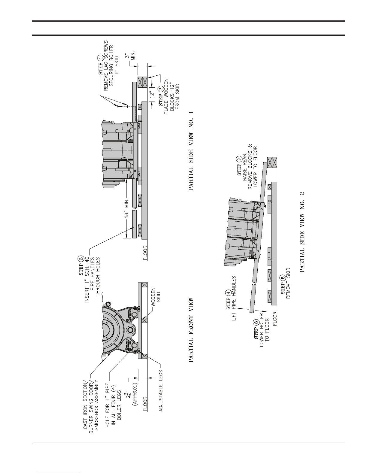
6. For manual Cast Iron Section/Burner Swing
Door/Smoke Box Assembly removal prepare
one piece of 4” x 4” x 16” lg. (or two pieces of
2” x 4” x 16” lg.) and two pieces of 1” Sch. 40
black pipe to be used as handles. Suggested
pipe length for each handle is 72” (3-section);
78” (4-section) and 84” (5-section).
7. Place wooden block(s) 12” from rear of skid
as shown. See Figure 4 “ Boiler Removal from
Skid”.
8. Insert 1” Sch. 40 black pipe handles thru leg
holes in front and rear section legs. Center rear
pipe ends on wooden block(s). See Figure 4.
9. For best leverage, the pipe handles should
extend 48” minimum beyond front section face.
10. Using the pipe handles, lift the Cast Iron
Section/Burner Swing Door/Smoke Box
Assembly until adjustable legs are elevated
above the skid deck boards.
11. Remove the skid from underneath the Cast
Iron Section/Burner Swing Door/Smoke Box
Assembly.
12. Lower pipe handles until front adjustable legs
touch the floor. Place wood blocks under front
legs, if required, before lowering, to provide
hand clearance.
13. To lower rear of the Cast Iron Section/Burner
Swing Door/Smoke Box Assembly tilt boiler
slightly forward by pushing on smokebox, or,
lift pipes protruding thru rear legs, until wooden
block(s) can be removed (see Figure 4). Slowly
allow the weight of boiler to tilt backward until
rear legs rest on floor.
14. If wood blocks were placed under front legs,
lift pipe handles; remove the blocks and lower
front legs to floor. Remove pipe handles.
15. Move Cast Iron Section/Burner Swing Door/
Smoke Box Assembly to permanent position by
sliding or walking.
CAUTION
Do not drop boiler when
removing from skid and moving to permanent
position.
C. PROCEDURE TO OPEN, CLOSE AND
SECURE BURNER SWING DOOR.
Throughout this manual you will be instructed to
open and close Burner Swing Door for various
reasons. There is a proper and improper method
of closing and securing the door opened for front
jacket panel installation, inspection, cleaning or
field service. Refer to Figures 5A, 5B, 5C and
paragraphs D “Jacket Front Panel Installation”,
and, F “Closing/Securing Burner Swing Door” for
details.
103536-08 - 4/18
Section II: Unit-Pak Boiler Assembly
(continued)
103536-08 - 4/18
Figure 4: Boiler Removal from Skid
11

Section II: Unit-Pak Boiler Assembly
(continued)
D. JACKET FRONT PANEL INSTALLATION.
In order to install front jacket panel Burner Swing
Door and door mounting bracket need to be
removed. As shipped, the door would open to the
left side.
1. To open/remove Burner Swing Door (mounted
on Cast Iron Section/Burner Swing Door/Smoke
Box Assembly) and door mounting bracket for
front jacket panel installation:
a. Loosen but not remove door left side
latching hardware (3/8”-16 x 1-3/4” tap
bolt).
b. Loosen and remove door right side latching
hardware (3/8”-16 x 1-3/4” tap bolt and
5/16” washer) and set aside.
c. Remove door left side latching hardware
(3/8”-16 x 1-3/4” tap bolt and 5/16” washer)
and set aside.
d. Lift the door off mounting bracket and set
aside.
e. Remove two 5/16”-18 – ¾” hex head cap
screws securing door mounting bracket to
front section and set aside.
f. Remove door mounting bracket and set
aside.
g. Note/mark cap screw bosses on front
section left side; locate/mark similar two
bosses directly opposite on front section
right side. These four front section bosses
are front jacket panel and door mounting
bracket attachment points.
See also Figure 7 “Purpose of Tappings &
Bosses”.
2. Open Jacket Carton and locate jacket front
panel (has factory attached 1” fiberglass
insulation). See also “Repair Parts” Section,
“Jacket Assembly” illustration for part
identification.
3. Open Part Carton, locate Hardware Bag,
remove two 5/16”-18 x ½” Phillips pan head
machine screws.
4. Place front jacket panel over front section
attachment bosses and align jacket holes with
front section boss holes.
5. Firstly, install two 5/16”-18 x ½” Phillips pan
head machine screws hand tight to secure
front jacket panel right side to casting
6. Secondly, insert 5/16”-18 – ¾” hex head cap
screw thru door mounting bracket upper hole
and upper hole on left side of front jacket panel
simultaneously, and, fasten the bracket and
panel to casting hand tight.
7. Thirdly, insert 5/16”-18 – ¾” hex head cap
screw thru door mounting bracket lower hole
and lower hole on left side of front jacket panel
simultaneously, and, fasten the bracket and
panel to casting hand tight.
8. Finally, tighten both sets of hardware to secure
the bracket and front jacket panel.
9. Inspect fiberglass rope located on the swing
door. The rope must be evenly distributed
around the perimeter of the door groove and
cannot bunch or overhang. Repair or replace,
Figure 5A: Partial Front View - Burner Swing Door Mounted to Boiler - Fully Closed and Secured
12
103536-08 - 4/18

Section II: Unit-Pak Boiler Assembly
(continued)
if the rope is damaged, or, there is a gap
between the rope ends.
10. Inspect burner swing door insulation for
damage and proper type.
By design, for all models, cast bars on front
section between the combustion chamber,
and, between the left and right side 2nd and
3rd pass flueways should make an impression
in door insulation to seal the chambers.
By design, door insulation on model MST629
will have two by-pass pockets cast into the
insulation centered on the bar between the
combustion chamber and 3rd pass flueways.
By design, door insulation on models MST288,
MST396 & MST513 will not have any bypass pockets. If insulation is damaged, or,
improper type regarding the pockets, it must
be replaced.
Figure 5B: Top View - Burner Swing Door Mounted to Cast Iron Block Assembly (Jacket Removed for Clarity)
103536-08 - 4/18
13

Section II: Unit-Pak Boiler Assembly
(continued)
11. Upon inspection completion, lift door and place
integral cast hinge pins into door mounting
bracket slotted holes. Do not close and secure
door at this time, proceed to installing stainless
steel flueway baffles.
12. Locate/remove four #8 x ½” shoulder sheet
metal screws from Hardware Bag, then, install
them into front panel flange holes.
E. FLUEWAY BAFFLE INSTALLATION.
Flueway baffles are enclosed into Part Carton.
Baffle requirements differ by boiler model, see
Table 2.
Table 2: Baffle Usage
Boiler
Model
MST288 None
MST396
P/N 100042-01
MST629
Baffle Usage
nd
2
Pass 3rd Pass
(2)
NoneMST513
NOTE: Read caution statement before
proceeding.
CAUTION
These baffles will generate
higher efficiencies and lower stack
temperatures. Under certain conditions,
a lower gross stack temperature entering
the chimney has the potential to be cooled
below the dew point and create condensate
on interior surfaces. Flue gas condensate is
corrosive, which requires special consideration
and must be addressed immediately.
DO NOT install baffles until you have read Section
V, "Venting" completely.
1. To install flueway baffles, provided in
miscellaneous part cartons, as follows, refer to
Figure 6 and
Table 2:
• Models MST396, MST513 and MST629 - To
install flueway baffle in 2nd pass flueway on
left side of boiler, hold baffle with word "Left"
readable at the top. Slide baffle in flueway
until position tab touches fins on right side
of 2nd pass flueway. To install flueway baffle
in 2nd pass flueway on right side of boiler,
hold baffle with word "Right" readable at the
top. Slide baffle in flueway until position tab
touches fins on left side of 2nd pass flueway.
Figure 5C: Top View - Burner Swing Door Fully Closed but Not Properly Secured or Sealed
14
103536-08 - 4/18

Section II: Unit-Pak Boiler Assembly
(continued)
tightening the hardware as far as possible
and then release the pressure.
NOTICE When securing burner swing door
make sure door is drawn-in equally on both
sides.
d. Use a hand or socket wrench to tighten
door hardware. ALWAYS START WITH
RIGHT SIDE TAP BOLT FIRST. Use an
alternating tightening method from right
side tap bolt to left side tap bolt to tighten
door equally, until sealed, without applying
excessive torque. NEVER TIGHTEN LEFT
SIDE TAP BOLT FIRST, OR, EITHER PIECE
OF HARDWARE 100% WITHOUT USING
THE ALTERNATING METHOD DESCRIBED
ABOVE. See Figure 5B.
e. Failure to follow the prescribed procedure
could cause thread damage to casting and
/or leak at the door seal. IF LEFT SIDE TAP
BOLT IS TIGHTENED BEFORE RIGHT SIDE
TAP BOLT, RIGHT SIDE OF THE DOOR
CAN NOT BE DRAWN-IN TO PROVIDE AN
AIR-TIGHT SEAL, as shown in Figure 5C.
Applying excessive torque will only cause
thread damage.
Figure 6: Flueway Baffle Positioning/Orientation
in Flueways
F. CLOSING / SECURING BURNER SWING
DOOR.
1. To close and secure Burner Swing Door:
a. From fully open position, rotate the door to
the closed position.
b. Lift door upward into the build-in cast ramp/
door rest (protruding from the bottom of the
front section casting – see Figure 5A).
c. Use one hand to apply pressure directly
to the door to hold it in closed position
while re-installing earlier removed doorlatching hardware (3/8”-16 x 1-3/4” tap bolt
and 5/16” washer). Prior to re-installation,
apply a drop of supplied Anti-seize (pouch
provided in Part Carton) to both tap bolts
for rust protection and to facilitate easy
removal, if burner door is to be open for
inspection and service. ALWAYS INSTALL
RIGHT SIDE LATCHING HARDWARE FIRST,
THEN INSTALL EARLIER REMOVED LEFT
SIDE HINGE HARDWARE (3/8”-16 X 1-3/4”
TAP BOLT AND 5/16” WASHER) SECOND.
Apply additional pressure while hand
G. JACKET REAR PANEL INSTALLATION.
1. Locate jacket rear panel (has factory attached
3” fiberglass insulation) inside Jacket Carton.
See also “Repair Parts” Section, “Jacket
Assembly” illustration for part identification.
2. Locate and remove from Hardware Bag rear
panel mounting hardware – (2 pcs) 5/16”-18 x
3” lg. tap studs, (2 pcs) 5/16”-18 plated acorn
nuts, (2 pcs) 5/8” x 2-9/32” round spacers
and (2 pcs) 5/16”-18 x ½” Phillips pan head
machine screws.
3. Locate rear panel two lower attachment bosses
on rear section. See Figure 7 “Purpose of
Tappings & Bosses”.
4. Thread both 5/16”-18 x 3” lg. tap studs, with
short threaded end, into lower attachment
bosses on rear section.
5. Install both 5/8” x 2-9/32” round spacers over
tap studs.
6. Place rear jacket panel over rear section, so
both tap studs clear thru lower panel holes,
rear section cleanout openings clear thru
matching panel cutouts and brass sample port
plug clears panel matching hole.
7. Secure panel bottom to studs with acorn nuts
hand tight.
103536-08 - 4/18
15

Section II: Unit-Pak Boiler Assembly
(continued)
Figure 7: Purpose of Tappings and Bosses
Table 3: Purpose Of Tapping & Bosses
Tapping
Location
A ¼" - 18 Pressure Gauge
B ¼" - 18 Pressure Limit
C ¾" - 14 Probe LWCO - Std.
D ½" - 14 Water Gauge Glass
E 2" - 11½" Supply (Front & Rear Tappings)
F ¾" - 14 Safety Valve
G 1½" - 11½ Condensate Return
H 1¼" - 11½ Optional Front Return
J 1½" - 11½ Surface Blowoff (Plugged)
K 1" - 11½ Indirect Water Heater Supply
L ½" - 14 Indirect Water Heater Limit
Q ¼" - 18 Smokebox Pressure Tapping
R ½"-14
Size, NPT
Boss
Location
M (4 pcs) 5/16" - 18
N (2 pcs) 3/8" - 16 Burner Swing Door
P (10 pcs) 5/16" - 18
Thread Size
UNC
Less Heater With Heater
Jacket Front Panel, Burner Swing Door
Jacket Rear Panel, Smoke Box Collar, Cleanout
Operating
Steam Boiler
Mounting Bracket
Covers
L4006
Control
Plugged
16
103536-08 - 4/18

Section II: Unit-Pak Boiler Assembly
(continued)
8. Align upper panel attachment holes with
smokebox upper attachment bosses and
install 5/16”-18 x ½” Phillips pan head machine
screws hand tight.
9. Securely tighten rear jacket panel mounting
hardware.
10. Locate/remove four #8 x ½” shoulder sheet
metal screws from Hardware Bag, then, install
them into rear panel flange holes.
H. FLUE CLEANOUT COVERS AND SMOKEBOX
COLLAR INSTALLATION.
1. Remove two cast iron Cleanout Covers, cast
iron Smokebox Collar and the tube of hitemperature silicon adhesive sealant from
Part Carton. See also “Repair Parts” Section,
“Bare Boiler Assembly” illustration for part
identification.
2. Check the rope gasket factory attached to
the covers. Repair or replace, if the rope is
damaged, or, there is a gap between the rope
ends.
3. Locate/remove four 5/16”-18 – 7/8” hex head
cap screws from Hardware Bag.
4. Apply a drop of supplied Anti-seize (pouch
provided in Part Carton) to each of four (4)
5/16”-18 x 7/8” hex head cap screws for rust
protection and to facilitate easy removal for
future service.
5. Position left Cleanout Cover over rear section
cleanout opening, align section boss holes
with Cleanout Cover holes, install both 5/16”18 – 7/8” hex head cap screws hand tight,
then, alternately tighten them with open end or
socket wrench.
6. Repeat above steps with right Cleanout Cover.
7. Apply the adhesive sealant to the underside
of the collar, all around, at the inside corner of
the collar outer ring. Insure adhesive bead is
complete all around and without gaps.
8. Place the collar over smokebox tongue and
align collar integral mounting ear slots with
smokebox bosses.
9. Thread-in both 5/16”-18 – 7/8” hex head cap
screws hand tight, then, alternately tighten
them with open end or socket wrench.
I. INSULATION WRAPPER AND BURNER
POWER OUTLET RECEPTACLE WITH
HARNESS INSTALLATION.
1. Insulation Wrapper is vacuum packed/sealed
in plastic bag at the factory.
2. Carefully cut the plastic bag and remove
Insulation Wrapper. The wrapper will expand
upon removal.
3. Unfold Insulation Wrapper, position it over
section assembly centered left to right and
align two wrapper upper holes with 2" NPT
pipe tappings in front and rear section top.
4. Insure wrapper fits snugly around rear section
tankless heater collar/ mounting flange (if boiler
is equipped with tankless heater) and trim the
insulation at tankless heater cutout.
5. Tack Insulation Wrapper bottom ends under
section assembly, between front and rear
section legs.
6. Locate and remove Burner Power Outlet
Receptacle with factory attached Burner
Harness from Control Carton.
7. Feed Molex end of Burner Harness thru front
jacket panel right side outlet receptacle cutout.
Insure that the receptacle middle prong
opening is facing down. Snap the receptacle
into front jacket panel. Temporarily, stuff Molex
end of Burner Harness between front panel
insulation and insulation wrapper near boiler
top.
J. SIDE AND TOP JACKET PANEL
INSTALLATION.
1. Pick up Left Side Jacket Panel from Jacket
Carton. See also “Repair Parts” Section,
“Jacket Assembly” illustration for part
identification.
2. Place Left Side Jacket Panel over four #8 x ½”
shoulder sheet metal screws, earlier installed
at Front and Rear Jacket Panel side flanges,
so teardrop cutouts in the side panel inside
flanges engage all four screws simultaneously.
3. Slide the panel downwards to lock all screws
securely.
4. Pick up Right Side Jacket Panel from Jacket
Carton. See also “Repair Parts” Section,
“Jacket Assembly” illustration for part
identification.
5. Pick up Molex end of Burner Harness
stuffed between front panel insulation and
insulation wrapper and feed it thru Right Side
Jacket Panel front cutout, letting the harness
connector to hang over the cutout edge
temporarily.
6. Place Right Side Jacket Panel, clearing rear
section tankless heater collar/ mounting flange,
103536-08 - 4/18
17

Section II: Unit-Pak Boiler Assembly
(continued)
over four #8 x ½” shoulder sheet metal screws,
previously installed at Front and Rear Jacket
Panel side flanges, so teardrop cutouts in
the side panel inside flanges engage all four
screws simultaneously.
7. Slide the panel downwards to lock all screws
securely.
8. Pick up Top Jacket Panel from Jacket Carton.
9. Place the panel between side panels upper
inside flanges and slide it forward, until top
panel front flange U-bend locks over front
panel top flange, and, top panel rear flange is
positioned over rear jacket panel.
10. Locate/remove two #8 x ½” sheet metal screws
from Hardware Bag.
11. Install both screws into top panel rear flange to
secure the top panel to rear jacket panel.
K. EXTERNAL ELECTRICAL ENCLOSURE
MOUNTING.
1. Remove two #8 x ½” shoulder sheet metal
screws and one #8 x ½” sheet metal screw
from Hardware Bag.
2. Install both #8 x ½” shoulder sheet metal
screws into Right Side Jacket Panel, at two
upper corners of the panel front cutout.
3. Locate and remove External Electrical
Enclosure assembly from Control Carton.
4. Remove the enclosure cover and set aside.
5. Pick Molex connector end of Burner Harness
and feed it inside the enclosure, thru bushed
hole at enclosure lower left corner, next to
transformer/relay.
6. Place the enclosure over installed shoulder
sheet metal screws, so teardrop cutouts in
the enclosure base engage both screws
simultaneously, then, slide the enclosure
downwards to lock it in place.
7. Install #8 x ½” sheet metal screw thru
enclosure base lower hole, located to the right
of transformer/relay, into right side panel to
secure the enclosure.
8. Plug-in burner harness Molex connector into
dedicated burner harness receptacle inside
the enclosure (lower left off transformer/relay).
See “ Control Plug-In Diagram” label attached
to inside of the enclosure cover for details.
9. Do not install the enclosure cover yet; proceed
to control installation.
L. TRIM AND CONTROLS INSTALLATION.
Pressure Limit Installation.
1. Locate and remove L404F Pressure Limit with
factory attached harness from Control Carton.
2. Locate and remove 1/4" NPT x 1-7/8" x 4 x 90°
syphon enclosed in Part Carton.
3. Review and locate pressure limit tapping
on front section. See Table 3 “ Purpose of
Tappings & Bosses” and Figure 7.
4. Thread 1-7/8" lg. syphon-threaded short end
into the bottom of Pressure Limit with factory
attached harness. Do not tighten the syphon
by holding the limit case; apply a wrench to the
brass hex below the case.
5. Thread ¼" NPT x 4" lg. syphon-threaded long
end into pressure limit tapping on front section.
See Figure 8 "Pressure Limit Installation.
Figure 8: Pressure Limit Installation
6. L404F pressure limit does not require leveling.
The pressure limit final orientation must be
parallel to boiler front, having the harness on
the right side.
7. Pick-up the pressure limit harness Molex end
and feed it into the enclosure, thru top flange
rear left 7/8” hole; then, snap-in harness BX
connector into the hole, and, plug Molex
connector into dedicated pressure limit
receptacle inside the enclosure (upper left
off transformer/relay). See “ Control PlugIn Diagram” label attached to inside of the
enclosure cover for details.
18
103536-08 - 4/18

Section II: Unit-Pak Boiler Assembly
(continued)
M. PROBE LWCO (HYDROLEVEL CG450,
OR, MCDONNELL-MILLER PSE801-120)
INSTALLATION.
1. Remove either Hydrolevel CG450 LWCO with
factory attached harness and Hydrolevel probe
#EL1214, or, McDonnell-Miller PSE801-120
with factory attached harness and #153875
probe from Control Carton.
2. Install the probe into the appropriate front
section tapping. See Figure 7 “Purpose of
Tappings & Bosses”.
3. Slip LWCO with factory attached harness
over the probe and clamp in place. Note that
CG450 LWCO will be positioned right side up,
with diagnostic LED(s) on the top flange, while
PSE801 LWCO will be positioned upside down,
with diagnostic LED(s) on the bottom flange.
Connect the wire(s) between the probe and
control per manufacturer’s instructions.
4. Pick-up the LWCO harness Molex end and
feed it into the enclosure, thru external
electrical enclosure top flange front left 7/8”
hole; then, snap-in harness BX connector
into the hole, and, plug-in Molex connector
into dedicated LWCO receptacle inside the
enclosure (middle left off transformer/relay).
See “ Control Plug-In Diagram” label attached
to inside of the enclosure cover for details.
N. PRESSURE GAUGE AND GAUGE GLASS
INSTALLATION.
1. Remove the 6” water gauge glass set from Part
Carton.
2. Install the gauge glass using the two ½” NPT
tappings to the right of the probe LWCO. See
Figure 7 “Purpose of Tappings & Bosses”.
3. Thread the pressure gauge into 1/4” NPT
tapping of the front section. See Figure 7
“Purpose of Tappings & Bosses”. Tighten with
wrench applied to the square shank of the
gauge.
CAUTION
Do not apply pressure to
gauge case, as this may result in inaccurate
readings.
O. AQUASTAT CONTROLLER INSTALLATION
(BOILERS WITH TANKLESS HEATER ONLY).
1. On boilers with tankless heater, install the
L4006A aquastat controller well (found in Part
Carton) into ½” NPT tapping in tankless heater
plate.
2. Remove the L4006A aquastat controller with
factory attached harness from Control Carton.
3. Slip the bulb of the aquastat controller into the
well and secure the controller in place with the
set screw.
WARNING
Aquastat bulb must be fully
inserted into the well.
4. Feed the L4006A aquastat controller harness
end thru external electrical enclosure top
flange middle right bushed hole. See “ Control
Plug-In Diagram” label attached to inside of
the enclosure cover for details.
5. See Figures 21 thru 21B (whichever
applicable) for tankless heater aquastat
connection details.
6. Using needle nose pliers form hook on
harness each stripped end and wrap hooks
around screws under terminals "R" and "G" of
the R8285C Transformer-Relay; then, tighten
screws securely.
P. SAFETY VALVE AND DRAIN VALVE
INSTALLATION.
1. Remove safety valve and related piping (3/4”
NPT x 3” lg. black nipple, 3/4” NPT x 8” lg.
black nipple, ¾” NPT 90° black elbow and ¾”
NPT black coupling) from Part Carton.
2. Thread 3/4" NPT x 3” lg. black nipple into rear
section safety valve tapping, install ¾” NPT 90°
black elbow facing upward, then, thread 3/4"
NPT x 8” lg. black nipple into the elbow, and,
install ¾” NPT black coupling onto nipple end.
3. Thread safety valve into the ¾” NPT black
coupling. Pipe the safety valve discharge as
shown in Figure 11 “ Recommended Boiler
Piping For Gravity Return Steam Boiler” shown
in Section III of this manual. Installation of the
safety valve must be consistent with ANSI/
ASME Boiler and Pressure Vessel Code,
Section IV.
WARNING
Safety valve discharge piping
must be piped near floor to eliminate potential
of severe burns. Do not pipe in any area where
freezing could occur. Do not install any shutoff valves, plugs or caps.
4. Remove 1-1/2" NPT x 5” lg. black nipple, 1-1/2”
x 1-1/2” x ¾” NPT black tee and drain valve
from Part Carton.
NOTICE Lower rear section Tapping "H" is
used for standard condensate return on steam
boilers.
103536-08 - 4/18
19
Section II: Unit-Pak Boiler Assembly
(continued)
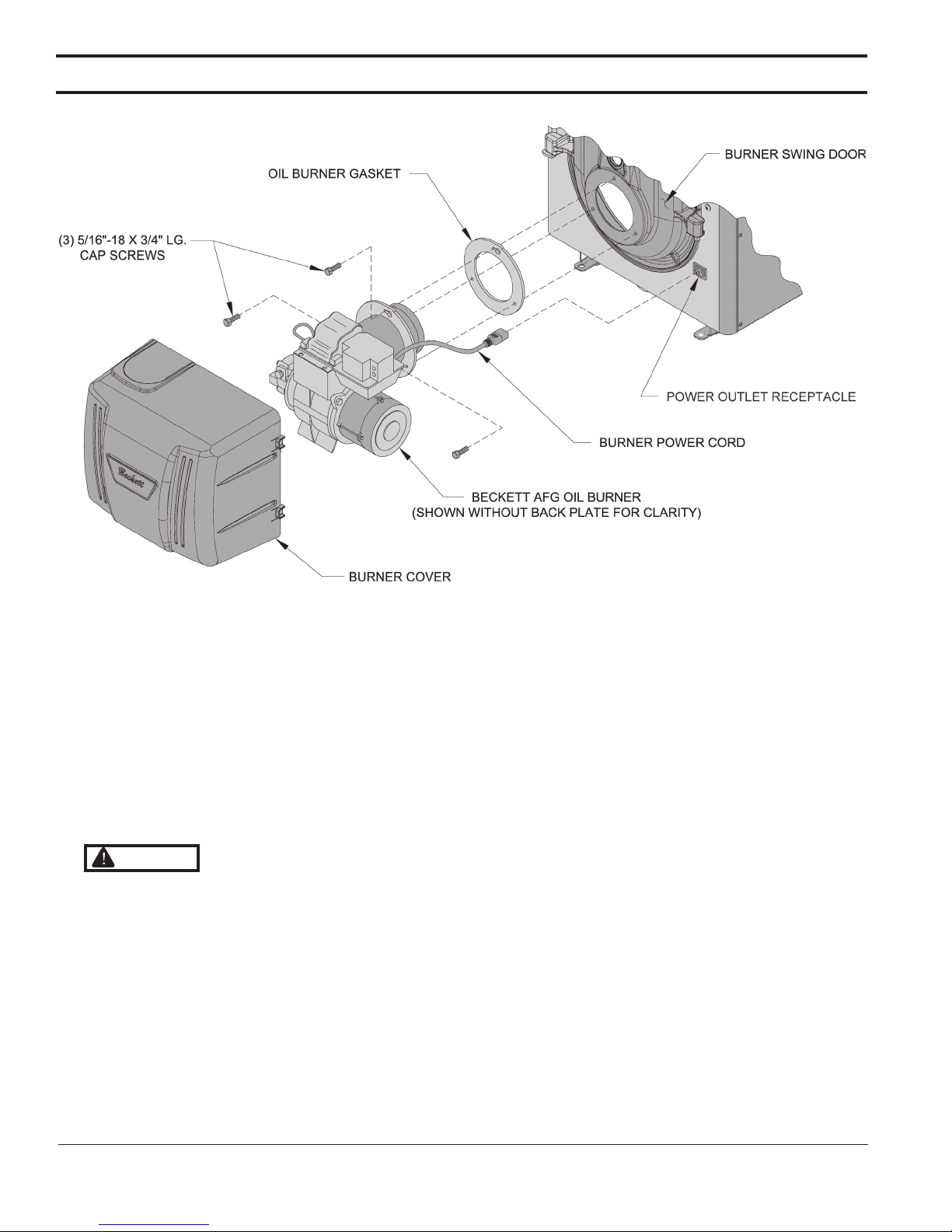
Figure 9: Oil Burner Installation (Beckett Burner Shown)
5. Thread 1-1/2" NPT x 5” lg. black nipple into
lower rear section tapping, then, install 1-1/2”
x 1-1/2” x ¾” NPT black tee onto nipple end.
Black tee side outlet may be oriented to either
left, or, right side.
6. Install the drain valve into black tee ¾” NPT
side outlet.
7. Install oil burner. (See Figure 9)
a. Open burner carton and remove contents.
b. Place oil burner gasket on burner and align
holes.
CAUTION
Do not install burner without
gasket.
c. Remove three (3) 5/16-18 x 3/4 lg. cap screw
from burner swing door used for mounting
burner.
d. Thread (1) 5/16-18 x 3/4 lg. cap screw,
approximately three (3) full turns, into
tapping located at 12:00 o'clock on burner
swing door.
e. Insert oil burner into the opening of burner
swing door. Align and engage keyhole slot
in burner flange over head of protruding cap
screw installed in previous Step. Rotate burner
to the right to lock flange behind head of cap
screw.
f. Align holes and install two (2) remaining cap
screws. Level burner and fully tighten all three
(3) screws.
g. Plug burner power cord into power outlet
receptacle located in lower right corner of
front panel.
h. Check oil nozzle in burner for size, angle
and spray type; inspect electrode settings
and head/air plate setting. Refer to Tables
11 thru 11B and Section VII. Refer to
Burner Manufacturer's Manual for detail
instructions.
20
103536-08 - 4/18

Section III: Steam Boiler Piping & Trim
WARNING
Failure to properly pipe boiler may result in improper operation and damage to boiler or
structure.
Do not increase steam boiler input above the ratings.
A. EVALUATE THE EXISTING STEAM SYSTEM.
The single most important factor in determining the
expected life cycle of a steam boiler, is the amount
of fresh water added to the boiler during operation.
Fresh water brings minerals and oxygen into the
boiler. These contaminants greatly accelerate
corrosion of the cast iron boiler sections.
1. Assure that all system radiators, piping and
vents are absolutely leak tight.
a. When a steam boiler is installed in an
existing system, ALL air vents should be
replaced at the same time. This assures that
the new boiler will not be compromised by
existing system leaks.
b. If the system contains hidden supply or
return piping (hidden behind walls, buried
in concrete, etc.) pressure test this piping to
assure there are no leaks.
2. Repair any leaks in the system.
3. Install accurate water meter on the fresh water
supply to the boiler.
B. CONNECT SYSTEM SUPPLY AND RETURN
PIPING TO BOILER. See Figure 11 for piping
details. Also, consult Residential Hydronic
Heating Installation and Design I=B=R Guide.
CAUTION
Maintain minimum ½ inch
clearance from hot water piping to combustible
materials.
C. Gravity Return Piping Kit.
1. Assemble Gravity Return Piping Kit for
MST288, MST396 and MST513 as illustrated in
Figure 11 for Recommended configuration or
Figure 13 for Dropped Header configuration.
See Table 4 for Recommended material
provided or Table 6 for Dropped Header
material provided for Boiler Models MST288,
MST396 and MST513.
2. Assemble Gravity Return Piping Kit for MST629
as illustrated in Figure 12 for Recommended
configuration or Figure 14 for Dropped Header
configuration.
See Table 5 for Recommended material
provided or Table 7 for Dropped Header
material provided for Boiler Model MST629.
Note: Tighten unions only after all piping is in the
proper position. Recommend using Pipe Dope
or Teflon Tape on all threaded surfaces.
NOTICE Do not use softened water in steam boilers. Accelerated boiler corrosion will result. Tie in fresh
water supply to the boiler upstream of a water softener.
Oxygen contamination of boiler water will cause corrosion of iron and steel boiler components, and
can lead to boiler failure. U.S. Boiler Company's Standard Warranty does not cover problems caused by
oxygen contamination of boiler water or scale (lime) build-up caused by frequent addition of water.
Before using copper for steam piping, consider the following characteristics of copper piping:
1. High coefficient of thermal expansion can induce mechanical stresses and cause expansion/
contraction noises if not accounted for in the piping system design and installation,
2. High heat transfer rate (heat loss) of uninsulated copper piping must be included in the normal
piping and pickup factors used to size the boiler,
3. Soldering or brazing pastes and fluxes that end up in the system can cause poor heat transfer,
surging, an unsteady water line and wet steam if not thoroughly removed during the boil out
procedure and,
4. Galvanic corrosion of the adjoining metal may occur due to dissimilar metals in certain water
chemistries if dielectric unions are not used.
103536-08 - 4/18
21
 Loading...