

U S Blindstitch 1099-CS-l-HH, B1099-CS-1-HH, F1099-CS-1-HH, S1099-CS-1-HH, 1099-T User Manual
...
U.S.
BUND
STITCH
EXPRESS
IMGHINE
STREET
&
SKYLINE
CABLE
ADDRESS:"BLiNSTlT
1099
COVERING
STANDARD
1099-CS-l-HH
B1099-CS-1-HH
F1099-CS-1-HH
S1099-CS-1-HH
DRIVE
TELEPHONE:
1099-PBW-I
CORP.
PLAINVIEW
PLAINVIEW
SERIES
THE
SUB
N.V.
11803
516-433-4350
NEW
YORK"
FOLLOWING
CLASSES;
1099-T
1099-T-l
1099-WB
1099-WB-l
EST.1925
MAINTENANCE
PARTS
©
1979•U.S.
CATALOG
BLIND
STITCH
MACHINE
&
CORP.

ni-MAINTENANCE
FOR
INTRODUCTION
A.
1118,1099
Replacing
the
INSTRUCTIONS
& 1108
Looper
SERIES
B. Replacing
C. Replacing
D. Replacing
the
the
the
Needle
Shoe
Feeder
Guide
MAINTENANCE
INTRODUCTION
INSTRUCTIONS
All U.S. BLIND STITCH machines are designed for long life and trouble-free performance. When
installed
and
lubricated
in
accordance
with
the
INSTALLATION
AND
OPERATING
INSTRUC
TIONS, only the minimum maintenance normally associated with industrial sewing machines will
be.required. These maintenance requirements will generally be confined to the four locations des
cribed below, at which wear may be expected
worn part may be readily replaced by following the appropriate instructions.
tion, and to insure satisfactory service, it is essential
after
extended
that
use. When such wear does occur, the
For
easeofinstalla
only genuine U.S. BLIND STITCH parts
and needles are used. They are the only parts designed specifically for the machine, with the built-
in long life and excellent wearing characteristics typicalofthe U. S. BLIND STITCH machine.
A.
REPLACING
THE
LOOPER
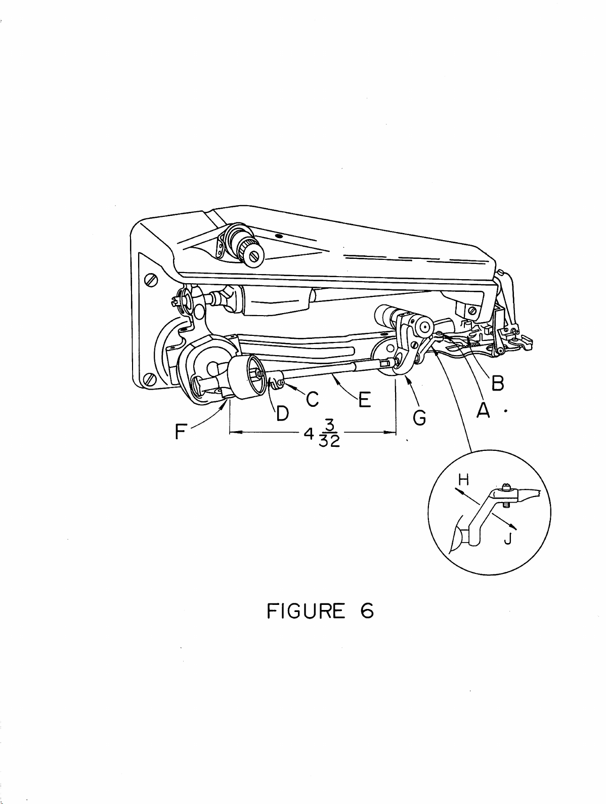
1. Should it become necessary to replace the looper (item
loosen the looper clamp screw (item
looper. Becauseofthe
precise fitofthe
necessary to exert a moderate
"A"
in Figure 6) and remove the old
looper
in the
amountofforce to pull the looper
"B"
looper
in Figure 6),
rod
it may be
out.
Insert
the new looperinto the endofthe rod as far as it will go before bottoming on
the
looper
shoulder.
2. Any time a looper is moved or changed, recheck the looper timing and reset
if necessary. Proper looper timing is absolutely essential for correct stitch
formation. As described in detail below, a properly timed
over the needle in the correct position to pick up
the
chain-off pin, feeder, looper slot, and needle. The first check
the looper is at the position where the looper picks the thread loop
looper
will pass
loop, and also clear
point
for timing
off
the
the
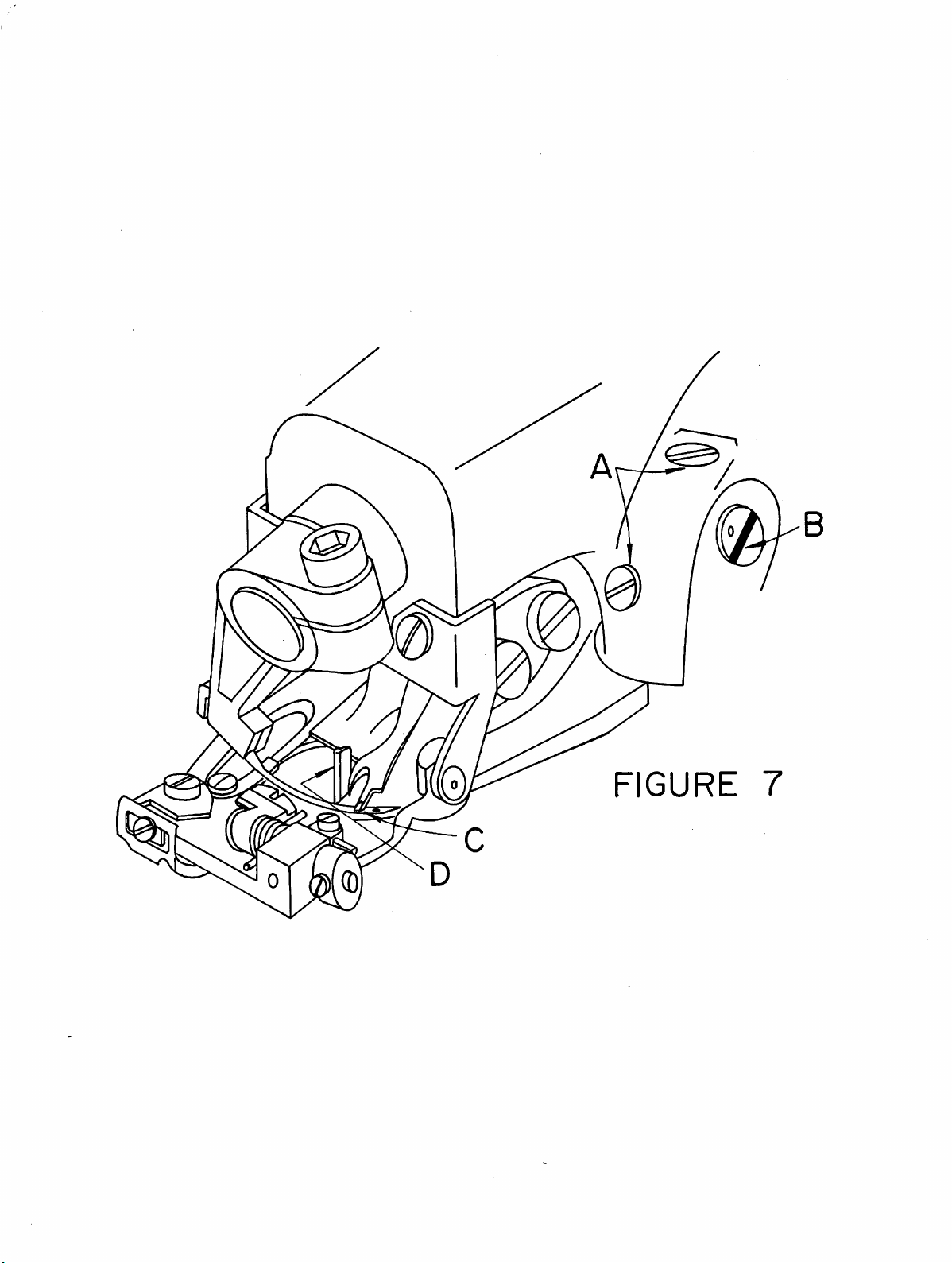
needle during the needle return stroke. Referring to Figure 7, (Point "C"),
the long prongofthe looper should pass over and
needle, approximately
the
same time, the
about
chain-off
1/64"
pin
(.406mm)
(item
3/32"
short
prongofthe
clearance, and
"D"
in Figure 7).
(2.4mm)
behind
looper should pass over
must
just
clear the scarfofthe
the
endofthe needle eye. At
be so
set
that
it also clears the
the
needle with
3. To adjust the looper so
it
mayberotated
shouldbemade
and
the
looper
out,
anddonot
amount
4.
If
timing, it will be necessarytoturn
This
in Figure 6).
Figure
in
If, for
rod
distance
the
inches
minor
of
the
adjustment
may
6).
ordertoget
any
has
been
from
rear faceofthe
(104mm)
adjustment
position. Note
variations
with
bottomed
attempttoforce
travel
be accomplished by loosening
The
It will
normally
the
reason,
disturbedbya large
the
(refer to Figure 6).Ifthe
that
maybeexpected
that
within
the
available.
describedinparagraph
rodisthen
looper
the
rod
centerofthe
looper
will be
this dimension is merely a guidetoassist in setting a
the timing checks
its
clampbya
looper
against
clamp
freetoturninthe
be necessarytomake
into
the
limited
screw
its
shoulder.
the
loopertoturn
3 is
the
looper
with
correct
(item
insufficienttoprovide
looper
rotational
has been removedorthe
amount,itmayberesetbynoting
rod
looper
ball (item
rod
fork
"G"
rod is
requiredtobring
from
machinetomachine.
the
out
as noted in paragraph 2,
amount.
Do
not
rod
looper
only
pin
This
adjustment
"A"
in Figure6)loosened,
move
the
looperinor
beyond
(item
rod
position
the
limited
"E"
in Figure6)itself.
clamp screw (item
rod
fork
(item
a very small
for
basic settingofthe
(item
"F"
in Figure6)to
the
"D"
adjustment
proper
looper
that
in Figure 6) is normally 4 &
settothis dimension
looper
into
the
correct
then
timing
correct
"C*
in
timing.
the
3/32
only
rod
and
5. If,
after
too
lowortoo
the two
slotofthe
raiseorlower
to see
ening
tained
handle
completing the above adjustments, it is found
high,itwill be necessarytoadjust
set
screws (item
eccentric
the
whether
the
by lightly
ofascrewdriver.
the
eccentric
tapping
looperasrequired.
stud
looper
block
"A"
in Figure 7). Place a wide blade screwdriver in the
(item
"B"
in Figure 7) and, using a slight
Once
the
proper
mustbemovedtothe
set
screws.Ifsuchamovementisrequired,itmaybeob
the
eccentric
blockinthe
that
the
eccentric stud.
height
leftorto
correct
the
looperiseither
turning
is established,
the
right
direction
First
loosen
motion,
check
priortoretight-
with
the
\
FIGURE
6
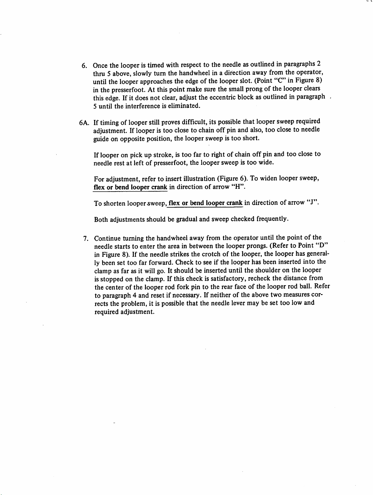
6.
Once
the
looperistimed
thru 5 above,slowly turn the handwheel in a direction awayfrom the operator,
untilthe
inthe
this
5
until
looper
approaches
presserfoot.Atthis
edge.
Ifit
does
the
interferenceiseliminated.
not
with
point
clear,
respect
the
adjust
edge
make
to the
of the
sure
the
needleasoutlinedinparagraphs
looper
the
eccentric
slot.
small
(Point
prong
"C" in
of the
looper
blockasoutlinedinparagraph
Figure
clears
2
8)
,
6A.Iftiming
adjustment.Iflooper
guideon opposite position, the looper sweep is too short.
If looper on pickup stroke, istoo far to right of chain off pin and too closeto
needle rest at leftofpresserfoot, the looper sweep is too wide.
For adjustment, refer to insert illustration (Figure 6). To widen looper sweep,
flex or bend looper crank in directionofarrow
To shorten looper
Both adjustments should be gradual and sweep checked frequently.
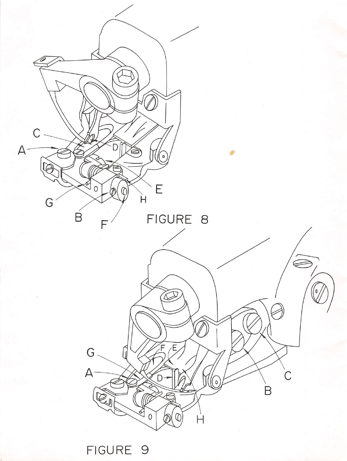
7. Continue turning the handwheel away from the operator until the point of the
needle starts to
in Figure 8). If the needlestrikes the crotch of the looper, the looper has general
ly beenset too far forward. Checkto seeif the looperhas beeninserted into the
clamp
isstopped on the clamp. If this check issatisfactory,recheck the distancefrom
the center of the looperrod fork pin to the rearface of the looper rod ball. Refer
to paragraph 4 and reset if necessary. If neitherofthe above two measures cor
rects the problem, it is possible that the needle levermay be set too low and
required
oflooper still
enter
asfar asit
adjustment.
proves
istoo
.sweep,
the area in between the looper prongs. (Refer to Point
will
go. It shouldbe inserteduntil the shoulder on the looper
difficult, its
closetochain
flex or bend looper crank in direction of arrow
possible
that
offpinand
"H".
looper
also,
sweep
too
closetoneedle
required
"J".
"D"
FIGURE
7
B.
8.
Once
clearanceisestablished
continue
passes
If
difficultyisexperiencedatthis
of
the
turning the handwheel away from the
between
previous
the
adjustmentstothe
If this is done, recheck
lished
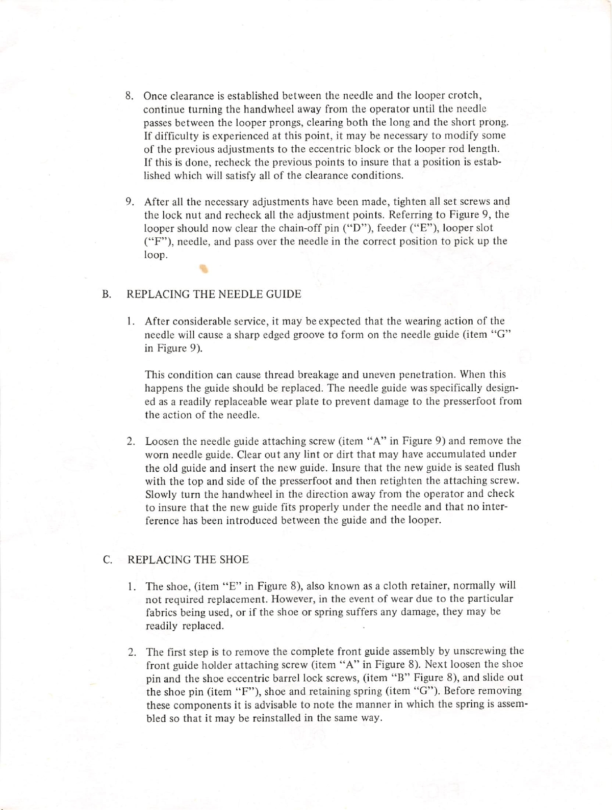
9.
After
the
looper
("F"),
loop.
REPLACING
1.
lock
After
which
all
will satisfy allofthe
the
necessary
nut
and
recheck
should now clear the chain-off pin
needle,
considerable
THE
and
NEEDLE
looper
pass over
service,itmaybeexpected
between
prongs, clearing
the
previous
adjustments
all
the
adjustment
the
needleinthe
GUIDE
the
needle
both
point,itmay
eccentric
points
clearance
have
blockorthe
to insure
conditions.
been
points.
("D"),
and
the
looper
operator
the
long
until
and
be necessary to
looper
that
a position is estab
made,
tighten
ReferringtoFigure 9,
feeder
correct
that
("E"),
positiontopickupthe
the
wearing
the
all
needle will cause a sharp edged groove to form on the needle guide (item
in
Figure
This
happens
ed as a readily replaceable wear
the
9).
condition
the
action
of
guide
the
can cause
should
needle.
thread
breakage
be replaced.
plate
and
uneven
The
needle guide was specifically design
penetration.
to prevent damage to the presserfoot from
crotch,
the needle
short
prong.
modify
rod
set
looper
actionofthe
some
length.
screws
slot
When
and
the
"G"
this
2. Loosen the needle guide attaching screw (item
worn needle guide. Clear
out
any
lint or dirt
"A"
in Figure 9) and remove the
that
may have accumulated
the old guide and insert the new guide. Insure that the new guide is seated flush
with
the
top
and
sideofthe
presserfoot
and
then
retighten
the
attaching
Slowly turn the handwheel in the direction away from the operator and check
to
insure
ference has
C.
REPLACING
1. The shoe, (item
not
that
the
new
been
THE
guide fits
introduced
SHOE
"E"
in Figure 8), also known as a cloth retainer, normally will
properly
between
the
under
guide
the
and
needle
the
looper.
and
thatnointer
required replacement. However, in the eventofwear due to the particular
fabrics being used, or if the shoe or spring suffers any damage, they may be
readily
replaced.
2. The first step is to remove the complete front guide assembly by unscrewing the
front guide holder attaching screw (item
pin and the shoe eccentric barrel lock screws, (item
"A"
in Figure 8). Next loosen the shoe
"B"
Figure 8), and slide
the shoe pin (item "F")» shoe and retaining spring (item "G"). Before removing
these components it is advisable to note the manner in which the spring is assem
bledsothatitmaybereinstalledinthe
same
way.
under
screw.
out
FIGURE
8
FIGURE
9
3. When replacing an old shoe, make sure that the replacement shoe properly fits the
pin without binding and without excessivelooseness. In the event that the pin has
worn and does not fit the new shoe properly, it should be replaced at the same time
as the shoe-pin.After replacingthe shoe, shoe pin springinto shoe eccentric barrel, re-
tighten screws (item
is linedupwith
the
openingofthe
"B"
the
centerofthe
presserfoot.
Figure 8), and check to insure
rib. Also insure
that
the
that
shoe
the
centerofthe
clears
both
shoe
sides
4. In and out position of shoeshould now be checked. For lightfabrics, shoeshould
be as close to needle as possible. For heavy fabrics with seam, shoe should be set
back
as far as possible from needle. To move shoe in
(item
"I"
screws,
Figure
(item
8). After the correct location isestablished, be sure to tighten
"B"
Figure 8).
and
out
turn
eccentric barrel
4A. An additionalshoe adjustment isalsopossible. The height of the shoe can now be
controlled, (item *'H"in Figure8). This is a tapered pin and position can be ad
justed so
concerned.
downon some
that
the shoe, whenever required, can be controlled as far as elevation is
By
moving
fabrics
the taperedpin in or out the shoe can be kept
whichrequire little, if any shoe pressure. By
from
having
pressing
this
control, it sometimes willaid in penetration of difficult fabrics. The normal posi
tionofthe shoe, when set properly on most fabrics, is that the shoe willshow move
ment
on the penetration cycle on one plyoffabric.
of
5.
REPLACING
THE
CHAIN
OFF
PIN
1. After considerableservice, it may become necessary to replacethe chain off
pin,
(Item
"D"
in Figure 7).
2. Remove the chain off pin attaching screwand remove the chain off pin, clean
out
any lint or dirt that may have accumulated. Attach the new chain
off
using the screw previously removed. Insure that the chain
of
the
side and forward edge
slot in the presserfoot, and then tighten the screw.
pin is against the
off
pin,
D.
REPLACING
THE
FEEDER
1. In the event that the machine
work, a worn feederis frequently found to be the cause.After considerableservice,
especially
dull, and the feeder should be replaced. In order to remove the old feeder, remove
the front feeder attaching screw (item
attaching screw (item
place. Insert the new feeder under the rear screwand replace the front screw.
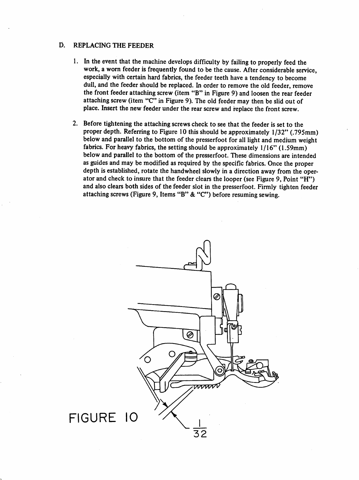
2. Before tightening the attaching screwscheck to see that the feeder is set to the
proper depth. Referring to Figure 10 this should be approximately 1/32" (.795mm)
belowand parallel to the bottom of the presserfoot for all lightand
fabrics. For heavy fabrics, the setting should be approximately 1/16" (1.59mm)
below and parallel to the bottomofthe presserfoot. These dimensions are intended
as guidesand may be modified as required by the specific fabrics. Once the proper
depth is established, rotate the handwheel slowlyin a direction away from the oper
ator
and also clears
attaching screws (Figure 9, Items
withcertainhard
"C"
and check to insure that the feeder clears the looper (see Figure 9, Point
both
sidesofthe feeder slot in the presserfoot. Firmly tighten feeder
develops
fabrics,
in Figure 9). The old feeder may then be slid
difficulty by
the
feeder
"B"
in Figure 9) and loosen the rear feeder
"B"&"C")
failing
teeth
have
before resuming sewing.
to properly
a tendency to
medium
feed
the
become
out
of
weight
"H")
FIGURE
cC
10

COVERING
1099
THE
SERIES
PARTS
FOLLOWING
CATALOGUE
STANDARD
SUB-CLASSES
5182
1401
5019
7004
1069
5174
3021
Side
Washer,
Screw,
Guard,
Screw,
Thread
Consists
7023
1324
1330
1329
7022
1811
Screw,
Cover
Side
Belt
Guard
Tension
Feed
1099-CS-l-HH
B1099-CS-1-HH
F1099-CS-1-HH
S1099-CS-1-HH
Assembly
Clamp
Cover
of:
Thread
Disc.
Post,
Spring,
Nut,
Pin,
Lever
r4AIN
Screw
Regulating
Guide
Thread
Thread
Tension
Tension
Spring
Plate
FRAME
Tension
Tension
1099PBW-1
1099-T
1099-T-l
1099-WB
1099-WB-l
GROUP
Ass'y.
1005
1006
1093
1289
1240
1089
7028
1096
1107
3281
1108
1080
1070
1054*
Tube,
Wick,
Screw,
Screw,
Pin,
Screw,
Plate,
Screw,
Screw,
Washer,
Screw,
Thread
Screw,
Washer
Oil
Oil
Set
Set
Presserfoot
Set
Top
Cover
Top
Cover
Bridge
Clamp
Clamp
Guide
Thread
Mtg.
Screw
Guide
♦Models
Do
not
1099-T,
have
washer
1099-WB
1054
and
1099
-WB-1

ASS
I
070
1
080
I
005
Y
324
5
74
006
I
096
006
7004
1054
328
MAIN
I
FRAME
50
19
I
093
GROUP

MAIN
SHAFT
GROUP
7012
5003-1*
See
Table*
*Sold
as
Main
Rib
1974
1973
1880
Needle
1072
1134-1
1132
1131-1
an
Assembly
**The
Shaft
Connection
Connection
Following
Screw
Screw
Screw,
Screw
Guard
Screw
Screw
Only
5188.-1
5240
5253
Lever
Eccentric
For
Cleunp
Ass*y.
Optional
&
Eccentric
Stud
Handwheel
Handwheel
Handwheel
Handwheel,
Positioner
Ass'y.
Ass'y.
With
Double
Double
Hub
Position
Pulley
Ass'y.
Are
Pulley
1845
5226**
See
Table
Available
Hub
Ass'y.
and
Collar
1971
Handwheel
3290
3291
3032
Stitch
Regular
1834
Ass*y.
Screw
Ass'y.
Handwheel
Screw
Pulley
Collar
Set
1121
1069
Screw
Ass'y.
Screw
Screw
Ass'y.,
Model
1099-CS-l-HH
B1099-CS-1-HH
F1099-CS-1-HH
S1099-CS-1-HH
1099PBW-1
1099T
1099T-1
1099-WB
1099-WB-l
Table
Needle
Ass'y.
5004-1
5004-1
5004-1
5004-1
5004-1
5004-1
5004-1
5041-1
5004-1
Connection
Stitch
Ass
5232
5232
5232
5232
5232
5231
5232
5231
5231
Collar
'y

2)I072
013-
>SEE
(2
086-
1013-
1014-
331-
I
013-1
1072
TABLE
701
(2)1834
SEE
5228
ASS'Y
C3C^
2
TABLE
SEE
FEED
(2)I974
p5003-l
y
//
DRIVE
GROUP
^1806
/ I069
ASS'Y-|
^
0
(2)197
(3)
l30-33n
3290
3032
i
!
1015
ASST
MAIN
SHAFT
I
880
GROUP
51
75
ASS'Y
ASS'^
5226-
ASS'Y

See
See
Table
Table
3019
3021
1821
See
Table
Feed
Feed
Feed
Screw
Thrust
1870
Feeder
1119
Lever
(Sold
Rocker
Lever
FEED
-
Lever
Collar
DRIVE
&
as
Plate
Set
Feeder
Stitch
Ass'y,
Ass'y.
Plate
Ass'y.
Screw
GROUP
Screw
Collar
only)
Ass
*y
Model
1099-CS-l-HH
B1099-CS-1-HH
F1099-CS-1-HH
S1099-CS-1-HH
1099PBW-1
1099T
1099-T-l
1099-WB
1099-WB-l
*Types
Feed
Rocker
Ass'y•
5023
5023
5023
5023
5016
5016
5023
5016
5016
of
Armoloyd
Carbide
Feed
Feeders
Table
Lever
Stitch
Collar
Ass'y.
5211
5211
5211
5211
5208
5208
5209
5208
5208
2125
2119
Available
Feed
Lever
Ass'y.
5229
5229
5229
5229
5228
5228
5228
5228
5228
Stitch
Collar
Ass'y.
5232
5232
5232
5232
5232
5231
5232
5231
5231
Feeder
2106
2106
2106
2106
2106
2100*
2106
2100*
2100*

SEE
TABLE
2
1
1834
SEE
TABLE
SEE
523
ASS'Y
TABLE
ASS
301
302
I
Y
9
SEE
(2)
TABLE
I I
19
FEED
DRIVE
GROUP

NEEDLE
DRIVE
GROUP
Short
5082
Needles
0
1
1
2
2
3
3
4
4
5
1/2
1/2
1/2
1/2
1/2
Needle
1076
3050
1137
1243
1136
Lever
Use
Long
Regular
Screw
Screw
Clamp
Pin
Lever
Genuine
Needles
Sizes
00
10
15
20
25
30
35
40
55
Ass'y.
Point
NEEDLE
U.S.B.S.
-
SIZES
System
AVAILABLE
Needles
251
Ball
Sizes
10
15
20
25
Point
5135
1095
For
Best
Collar
1089
Shaft
1118
Results
Spear
Ass'y.
Screw
Screw
Point
Sizes
10
15
20
25
30
35
65

^1
37
IMS
5082
J
ASS-Y^
'243
II36
076
NEEDLE-SPECIFY
SIZE
(2)1
REQUIRED
089
3050
NEEDLE
DRIVE
GROUP

LOOPER
DRIVE
GROUP
Part
2200*
1150
5233
5230
5213
5186
5206
No
Description
Looper
Stud,
Looper
Collar
1870
Looper
Consists
1154
1155
3049
1979
1123
1146
5006
1094
Looper
Consists
5185
1154
3049
1979
Looper
Consists
5017
1117
5185
Looper
Consists
5186
1154
3049
1979
Ass*y.
Set
Rod
of:
Fork
Pin
Screw
Nut
Stud
Nut
Looper
(Not
Screw
Rod
of:
Looper
Fork
Screw
Nut
Rod
of:
Looper
Screw
Looper
Rod,
of:
Ass'y.
Fork
Screw
Nut
Adjustment
Screw
Fork,
sold
&
Fork
&
Carrier
Fork
Sleeve
Rod
Sleeve
separately)
Ass'y.
Rod &
Rod
Rod &
&
Carrier
&
Ball
Ass'y.
Carrier
Ball
Stud
Ass'y
Ass'y.
Ass'y.
Ass'y.
Ass'y.
Ass'y
*2201
Looper
Used
with
S1099-CS-1-HH

ASSY
5006
ASSY
094
1979
I
23
ASS'Y
5
86
ASSY
LOOPER
DRIVE
GROUP

FEED
FRAME
I
GROUP
Model
1099-CS-l-HH
B1099-CS-1-HH
*F1099-CS-1-HH
*S1099-CS-1-HH
1099-FBW-l
1099-T
1099-T-l
1099-WB
1099-WB-l
***1262
See
See
**Rib
*1995
***In
Table
Table
Rib
Ass'y.
Ass'y.
8086
8024
8017
8021
place
5179
1836
5167
7018
1864
1056
1244-4
1146
1029
1167
Shaft
8067-1
8096
8096
8096
8086**
8024**
8024**
8017**
8021**
Shaft
Roller
Feed
Collar
1079
Rib
1117
Plate,
Screw,
Post,
Nut
Flatten,
Screw,
Nut
Nut
Screw,
Nut,
Flatten
Left
2400
Roller*
7140
2436
2422
2400
2400 2401
2400
2400
2400
Rib
2081
2020
2017-1
2017
Screw
of
1710
Frame
Shaft
Spring
Flatten
&
Ass'y.
Ass*y.
Set
Crank
Screw
Window
Plate
L.H.
Flatten
Cylinder
Flatten
Right
2401
2435
2437
2423
2401
2401
2401
2401
Rib
Pawl
2083
1262
Screw
Lock
Fin
Fin
use
Ass'y.
Flatten
Bkt
Left
2473
2473-1
2482-1
2482-1
2473
2473
2473
2466
2466
Rib
Hub
——
2021
2018-1
2019
part
3013
3013
n
/
TABLE
Flatten
Bkt
Right
Fin
Fin
Collar
1373
nos.
See
See
See
See
Table
Table
Table
1069
1021
Table
***1710
1055
See
Table
1113
1105
See
Table
7014
Spring
2474
2474
2481-1
3013
2481-1
3013
2474
2474
2474
2465
2465
3062
3065
1172
4
1172
4
3062
3062
3062
3062
3062
Req'd
Req'd
Spring
1376
1306
1307
1307
1132(2), 1114(2),
Stud
1379
1379-1
1379-1
•
1379
•
1379
1379
1379
1379
1379
Screw
1377
1935
1377
1377
BKT,
BKT,
Stud
Set
Screw
Spacer:-
Spring
Screw,
Post
Flatten,
Screw,
Screw
Cylinder
Shaft,
Cylinder
1168(2)
L.H.
R.H.
7025
7025
7025
7025
7025
Nut
1881
1881
1881
Flatten
Flatten
1021-1
Limit
R.H.
Frame
Rocker
and
=
-2
=
Cylinder
Screw
1966
1966
1966
1966
1966
7150

2017-1
2021^
^2020
2081
(2017)
2018-
(2019)
8017
(8021
ASS'Y
ASS'Y)
(2)1244-4
SEE
SEE
(2)1167
1307
TABLE
TABLE
SEE
SEE
TABLE
TABLE
SEE
TABLE
(2)
1373
5167
1935
—
8024
ASS'Y
1306
ASS'Y
SEE
(2)1864
7019
TABLE
1836
2083
ASS
8086
Y
1376
ASS'Y
SEE
SEE
TABLE-
TABLE
1055
(2)1262
(2)1710
SEE
TABL
FEED
FRAME
069
7014
GROUP
1836
ASS'Y
5179
ASS'Y
1146
I

FEED
FRAME
GROUP
II
5020
1146
1177
1184
*1190
5163
3055
1061
5235
7013
1060
1838
4544
5162-H
131-31
Spring
1176
Nut,
Ret'ng.
Screw,
Nut,
Main
Lift
Spring
Spring
Arm
1335
1855
1334
1120
1035
1008
Collar
1992
Spring
Knee
Pedal
1208
1037
Key
Vertical
Nut
Pad,
Pedal
Horizontal
Pin
Link
Pin
Link
Ass*y.
Lift
Screw
Hook
Screw
Screw
Nut
Ass'y.
Set
Knee
Screw
Offset
Ass'y.
Arm
Screw
Ass'y.
Pedal
Rod,
Rod
Knee
Press
♦Subclasses
use
Spring
See
last
classes
S1099-CS-1-HH.
F1099-CS-1-HH
1660
page
B1099-CS-1-HH,
for
diagram
and
S1099-CS-1-HH
of
lifter
F1099-CS-1-HH
for
and
sub

51
79
ASS'Y
5I62H
(2
1 I
20
5163
ASS'Y
I
06
3055
ASS'Y
I
131-3
S)
70
I
838
1060
46
I
177
I
184
3
5020
ASS'Y
4544
FEED
FRAME
GROUP
H

REGULATING
GROUP
1186
5012
1025
5177
Regulating
Push
Rod
1023
1024
Pin
Regulator
1109
5173
5178
1223
1222
1977
Fork
Ass'y.
Pin
Spring
Ass'y.
Screw,
Dial
Dial
Shoe
Screw
Screw
-
Regulator
&
Ratchet
Plate
Complete
Ass'y,
Ass'y.

1223
1222
5178
5177
ASS*Y
<1
ASS
ASS
5173
Y
Y
(2)
1109
REGULATING
5012
ASS'Y
1024
GROUP

Partial
Ass'y.*
See
PRESSERFOOT
Table
GROUP
Presserfoot
Consists
See
1238
1933
See
1866
1102
Table
Table
of:
Presserfoot
Pin
Screw
Needle
Screw
Screw
Ass'y•
-
"Chain-Off"
Guide
(Partial)
Model
1099-CS-l-HH
B1099-CS-1-HH
F1099-CS-1-HH
S1099-CS-1-HH
1099-PBW-l
1099-T
1099-T-l
1099-WB
1099-WB-l
Complete
Ass'y•**
Shoe
2540
2541
2540
2541
2521-1
2511
2521
2510
2517
Shoe
Ass'y,
5215
5216
5215
5216
5078-
5074-
5078
5064
5077
See
1308
1075
1133
See
See
1099
1079
7026
Anchor
3024-1
3024-1
3024-1
3024-1
3024-1
Fitted
1418-B
3024-1
Bracket
1242
3024
Table
Table
Table
Shoe
Pin
3294
3294
3294
3294
3294
3294
3294
1237
3294
Shoe
Screw
Screw
Screw
Pin
Bracket
Screw
Screw
Bridge
Bushing
7210
7210
7210
7210
7210
7210
7210
3068-1
3068-1
1372
1305
3067
See
3025
1976
See
1107
1864
TABLE
Guide
2606
2606
2606
2606
2606
2606
2606
2606
Table
Table
Spring
Spring
Wedge
Bushing,
Spring
Set
Guide
Screw,
Screw
Chain-Off
Pin
1831
1831
1831
1831
1831
2900
2900
2900
2900
Screw
Shoe
Bridge
Presserfoot
2373
2373
2373
2373
2359
2358
2359
23
2350
Adjustment
Mtg.
52
Partial
Ass'y.*
8503
8503
8503
8503
8509
8508
8509
8502
8500
Complete
Ass'y.**
8603
8616
8603
8616
8618
8619
8620
8621
8617

2
1075
1308
1305
(2)^107
1864
075
054
SEE
3025
SEE
1099
SEE
SEE
1079
TABLE
TABLE
TABLE
TABLE
PARTIAL
ASS'Y
SEE
I I
SEE
TABLE-
33
TABLE
SEE
TABLE
SEE
866
1933
TABLE
I
108
COMPLETE
PRESSERFOOT
ASS'Y
SEE
GROUP
TABLE

See
Table
1051
5015
1227
1052
1053
1051
3016
FRONT
Swing
Screw
Stop
Stop
Screw
Washer
Set
Spring
Pin
Plate
Screw
PLATE
Plate
Ass'y.
Washer
TABLE
GROUP
1225
3026
7009***
1103
1230
1229
1226
Pivot
Retaining
Support
Screw
Washer,
Washer
Collar
1992
Pin
Bracket
Flat
,
Lock
Ass'y.
Ring
Set
Screw
Model
1099CS-1-HH
***B1099-CS-1-HH
F1099-CS-1-HH
S1099-CS-1-HH
1099-PBW-l
1099-T
1099-T-l
1099-WB
1099-WB-l
***Board
Support
r
under
Bracket
Swing
Plate
7006
7006
7037
7006
7037
7037
machine
7060
7200
Swing
Plate
Ass
*5251
*5251
**5265
*5251
**5265
**5265
'y.
Stationary
Plate
7036
Stationary
Plate
Ass
'y.
5264

SEE
TABLE
30
6
5015
ASS'Y
2
1053
2
1230
(2
1229
(2)1103
ASS
7009.
Y
+
COMPLETE
*•
COMPLETE
FRONT
ASS'Y
ASS'Y
PLATE
GROUP
NO.
NO.
5251
5265

132
(2)4533
7
1326
i
1037
3
7-
(2)1230
(2)1229
(2)
1103
7035
'M
2)1230
(2)1229
COMPLETE
FRONT
ASS
PLATE
Y.
NO
GROUP
(2)1341
5264

REAR
OF
70
1 3
5179
m
I
ASS
Y
MAIN
WALL
FRAME
•
II
I
177
879
1008
17
r
fc
5020
ASS'Y
4544
MAI
FRAME
\
ASS
N
(21414
(2I393
I
271
Y
120^
FEED
FRAME
GROUP
5235
n
ASS'Y

A
MachineisOnly
as
Good
as
its
NEEDLE!
Don't
Top-quality
with
wash
saved on
U. S. specifications of the finest materials and workmanship available.
recognition
in U. S. needles is the knowledge
foremost
unequalled.
and
quality
curvature
top-quality
Peak
and
wear
and
performance.
Imitations
inferior
U. S.
The
and
in
our
For
Their
Take
needles
efficiency
fabrics
or
needles only prove to be expensive dollars in
Blind
quality
cannot
products.
durability
uniform
assure
efficient,
Chances—Avoid
sewing
to
is
accomplished
substitutes
Stitch
of U. S. Needles is, in
be
duplicated.
and
demands
achieve
in
today's
needles
that
freedom
construction,
economical
top-quality
perfect
high-speed
only
areacostly
are
made
The
confidence
quality is and always has been
from
carefully
stitching.
Trouble
machines
results.
sewing
with
needles
compromise.
in
the
fact,amatter
of
breakage,
controlled
of
of
United
our
U. S.
equipped
synthetic
superior
Pennies
the
long
States
of
world-wide
customers
Needles
finish
and
run.
to
are
BE
GENUINE
Lix^
on
The
perfection exists in all U. S. Machine Parts.
BE
SURE
fot
ail
same
SURE
TO
U.
S.
fhk
parts
precision
TO
GET
USE
ONLY
NEEDLES
ldi>e/
construction
U.
S.
—
and
working
ACCEPT
GENUINE
U.S.
NEEDLES
U.S.
BUND
MACHINE
Express
and
Skyline
Plainview.NewYofk 11803
Made
NO
SUBSTITUTE
in
STITCH
CORP.
Street
Dfive
U.S.A.
#4452/6-80
PREVTON,
LITHO
U.S.A.
 Loading...