

U.ii.BUNDiSTITCH
EXPRESS
MACHINE
STREET
&
CABLE
SKYLINE
ADDRESS:"BLINSTIT
DRIVE
TELEPHONE:
CORP.
PLAINVIEW
PLAINVIEW
INSTALLATION
OPERATING
INSTRUCTIONS
MAINTENANCE
PARTS
CATALOG
N.Y.
U803
516-433-4350
NEW
YORK"
AND
&
for
EST.1925
Model
U.S.
Blind
1979•U.S.
Stitch
BLIND
Machine
STITCH
MACHINE
099SF/1200SF
CORP.
NOTE
FOR
PARTS
CATALOG
The
1200SF
modified
However,
changed.
to
this
unit,
numbers
Please
when
ing
service
and
only
parts
just
have
indicate
ordering
has
renamed
a
You
may
book
note
been
parts
information.
recently
few
still
where
changed.
serial
10099SF.
parts
for
or
been
are
refer
either
part
number
request

MACHINE
MODEL
NO.
a
o
000000
PARTS
BE
CATALOGS
SURE
OF
MACHINE
TO
ARE
SPECIFY
WHEN
AVAILABLE
MODEL
ORDERING
AND
MACHINE
SERIAL
UPON
SERIAL
PARTS.
NO.
REQUEST
NO.
1099SF/1200-SF
All
U.S.
trouble-free
accordance
only
the
sewing
ments
below,
such
following
tion,
will
wear
and
INSTALLATION,
Blind
performance.
with
minimum
machines
generally
at
which
does
the
to
insure
Stitch
the
INSTALLATION
maintenance
will
wear
occur,
appropriate
satisfactory
OPERATING
INSTRUCTIONS
Machines
be
required.
be
confined
may
be
the
worn
instructions.
When
normally
expected
part
are
installed
AND
to
service,
AND
MAINTENANCE
designed
OPERATING INSTRUCTIONS,
associated
These
the
after
may
for
and
lubricated
maintenance
five
be
extensive
readily
For
it
locations
ease
is
long
life
with
require
replaced
of
installa
essential
industrial
use.
and
in
described
When
by
that
only
They
with
typical
genuine
are
the
the
built-in
of
the
U.S.
only
U.S.
Blind
parts
long
Blind
Stitch
designed
life
Stitch
and
parts
specifically
excellent
Machine.
and
needles
wearing
are
for
the
characteristics
used.
machine,
I.
UNPACKING
A.
UNPACKING
1.
AND
INSTALLING
Cardboard
INSTALLATION
THE
Carton:
INSTRUCTIONS
MACHINE
Open
the
carton
and
remove
the
B.
C.
corrugated
the
carded.
plywood
attaching
for
FITTING
1.
The
LOCATING
1.
The
table
machine
accessories
Lift
base
the
use
in
THE
MACHINE
machine
THE
MACHINE
1200-SF
top.
as
liner.
is
the
still
plywood
mounting
TO
should
is
set
After
noted
Insure
not
misplaced
machine
attached.
base,
the
THE
TABLE
be
mounted
WITH
RESPECT
even
establishing
above,
that
out
and
machine.
TOP
with
move
the
of
Next,
on
TO
the
the
it
envelope
or
accidentally
the
carton
remove
set
the
a
blank
THE
front
position
sideways
bolts
TABLE
edge
containing
with
the
table
EDGE
of
of
until
dis
the
bolts
aside
top.
the
the
the
machine
The
belt
the
belt
has
been
in
the
the
table
place
table
and
install
Insure
the
bolts
handwheel
slot
to
established.
base
top.
the
felt
top,
that
securely
may
insure
of
replace
the
the
lines
now
that
the
machine,
Drill
pad,
attaching
machine
be
Mark
3/8"
supplied
the
machine
fastened.
up
the
is
cut
bolts,
with
in
correct
the
and
holes
with
firmly
the
the
center
remove
for
in
washers
motor
table
machine
the
each
its
proper
clamped
drive
top.
location
of
the
the
machine
mounting
machine,
and
in
pulley.
Install
bolt
on
location
nuts.
position
holes
from
bolts,
the
and
2,
Position
the
thread
stand
behind
the
machine
to
the
D.
MOTOR
1.
2.
right
supplied
The
of
DRIVE
machine
bination
the
correct
ing
recommendations.
unit
rated
a
Either
When
is
at
2-1/2"
V-belting
installing
the
handwheel,
wood
is
which
speed
employed,
1/3
HP
pulley
screws.
shipped
is
properly
when
it
and
should
or
the
and
with
used
When
is
recommended
1750
be
round
belt,
secure
a
handwheel
sized
in
accordance
an
individual
RPM. On
used.
leather
use
just
in
to
insure
that
all
belting
enough
place
and
operation
with
motor
the
standard
may
tension
with
pulley
the
and
motor
models,
be
the
com
at
follow
clutch
be
used.
to
prevent
belt
wear
slippage.
and
can
Excessive
possibly
tension
damage
the
will
machine
cause
rapid
II.
OPERATING
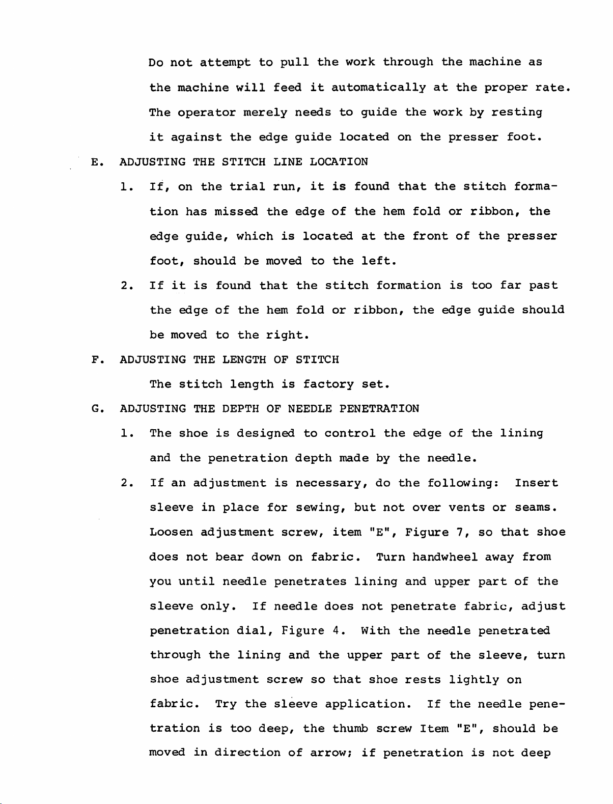
A.
LUBRICATING
1.
INSTRUCTIONS
Before
THE
MACHINE
operating
the
machine,
it
is
extremely
important
B.
that
following
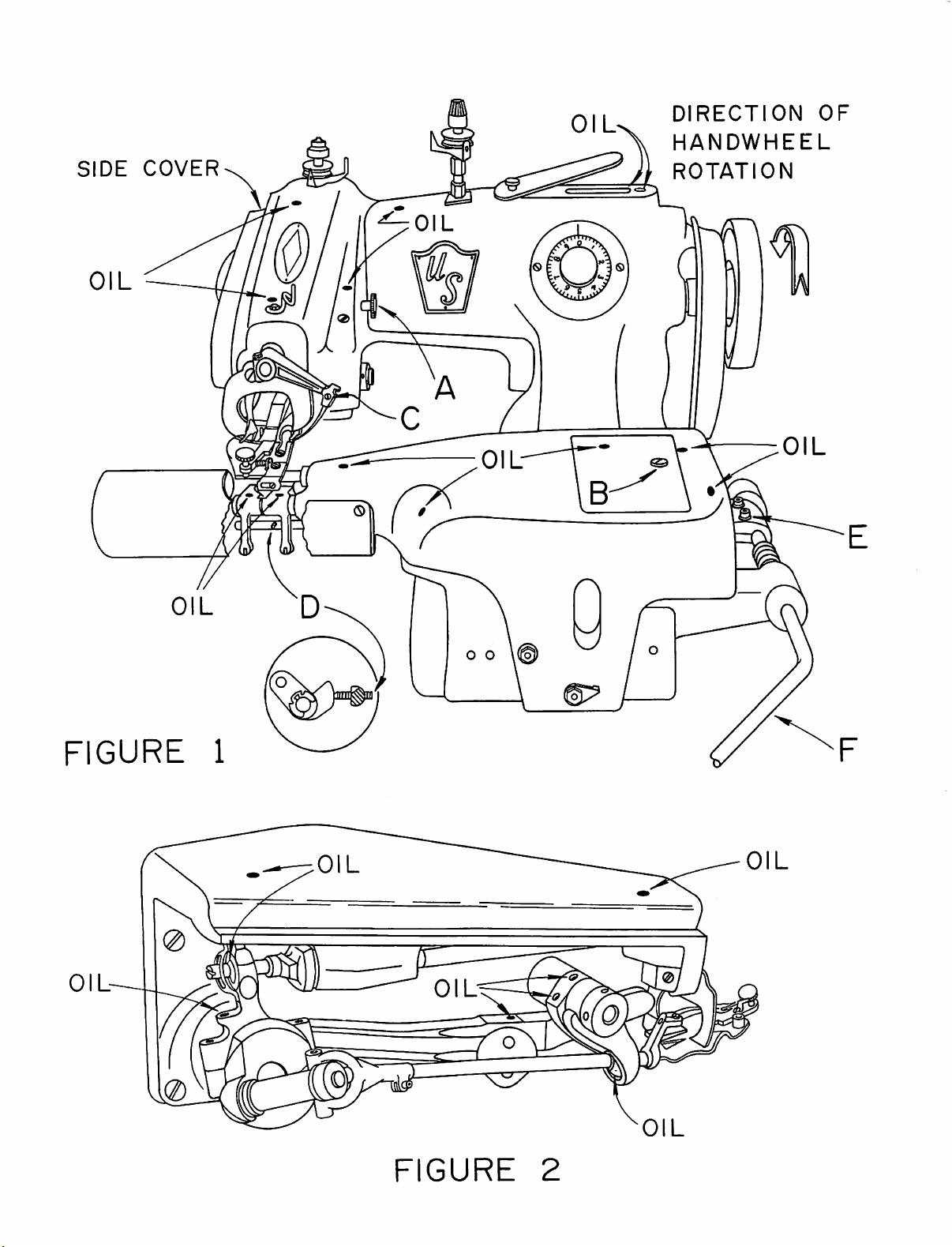
2.
Place
oiling
on
Then
the
3.
In
daily
Item
ADJUSTING
1.
In
lifter
it
be
a
few
chart
Figure
place
oiling
prpduction
basis
2
above.
THE
order
to
may
properly
instructions.
drops
in
Figure
1
by
loosening
a
few
drops
chart
in
use,
in
accordance
KNEE
insure
be
LIFTER
adjusted.
lubricated
of
oil
Figure
the
optimum
at
all
1.
Remove
the
of
oil
2.
machine
with
operator
in
the
cover
at
should
the
accordance
points
the
table
attaching
all
the
be
instructions
comfort,
shown
cover
points
oiled
with
bolt
on
the
the
on
shown
"A".
shown
a
in
knee
the
on
C.
2.
To
(Item
lifter
then
THREADING
1,
Use
being
ized
2.
Prior
should
until
of
position
place
tighten
any
00/2,
it's
E,
pad
THE
type
sewn.
to
be
the
swing.
lifter
Fig.
is
screws.
MACHINE
of
This
70/2
starting
turned
needle
for
threading.
pad
1)
and
in
comfortable
thread
includes
and
the
in
reaches
This
in
proper
push
which
nylon
threading
the
will
down
mercerized,
K15
direction
the
put
position,
on
position
is
suitable
or
K13.
operation,
extreme
it
into
rod
away
(Item
for
nymo
from
right
the
loosen
operator
for
the
hand
most
two
F)
until
the
000,
handwheel
the
convenient
screws
the
knee,
work
mercer
operator
portion
SIDE
COVER
DIRECTION
HANDWHEEL
ROTATION
OF
OIL
a,
FIGURE
OIL-
1
OIL
0
OIL
FIGURE
2
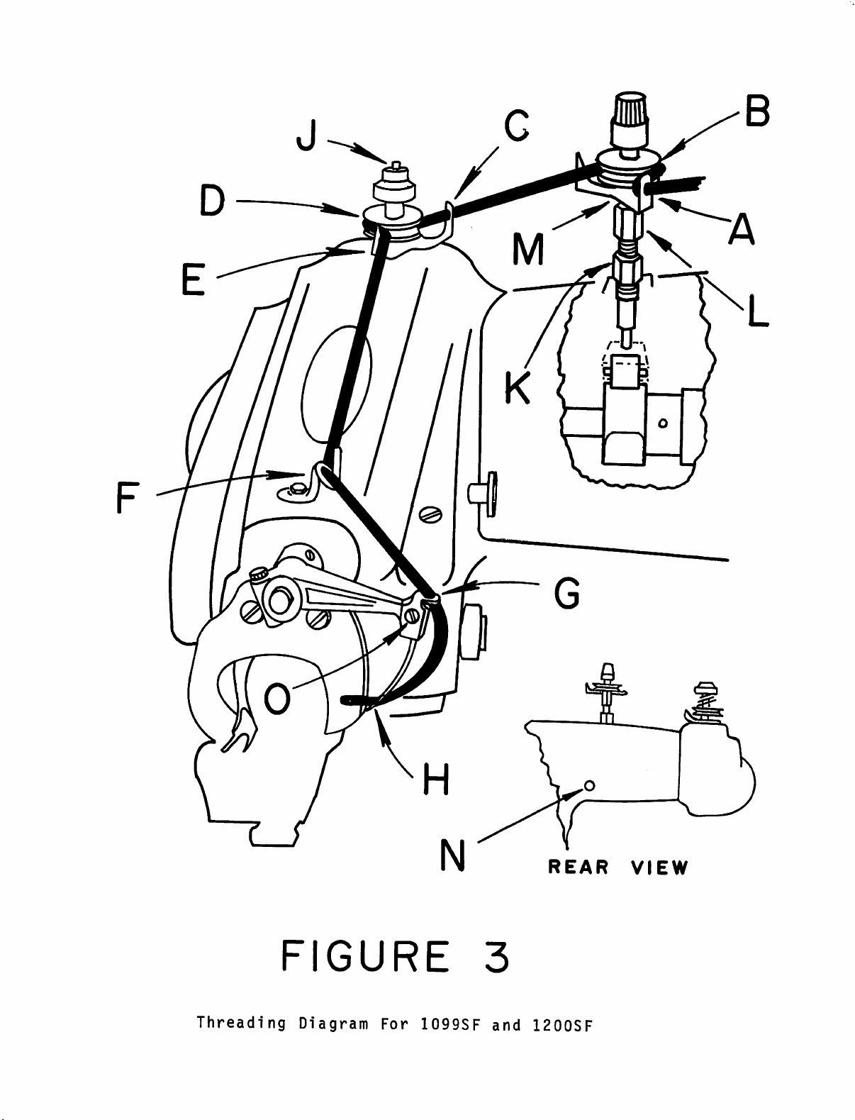
3.
Referring
to
the
threading
chart
in
Figure
3,
it
can
be
D.
seen
thread
"A".
and
then
brought
"F".
hole
ing
the
past
INSERTING
that
is
slides
"G",
on
top.
the
is
It
carried
forward
It
the
THE
the
passed
then
between
then
then
underside
The
eye
of
WORK
threading
from
slides
to
the
along
is
passed
through
thread
the
IN
THE
front
between
left
the
"E"
the
of
should
needle
MACHINE
procedure
to
the
through
two
tension
through
through
eye
the
needle
be
by
back
the
of
pulled
a
few
is
two
the
the
a
through
tension
guide
discs
front
needle
needle
and
through
inches.
simple
hole
"D"
being
one.
guide
discs
"C".
and
thread
clamp
"H",
removed
to
The
hole
"B"
It
is
guide
guide
enter
at
extend
1.
2.
3.
Prior
to
turned
needle
swing.
The
knee
the
feed
and
the
The
work
edge
loaded
of
leased
important
operator's
inserting
in
the
reaches
lifter
frame
plattens.
is
the
cloth
which
to
direction
inserted
lining
retainer
locks
insure
knee
the
is
and
is
the
work,
away
extreme
then
pressed
creates
underneath
fold
the
or
or
work
that
not
permitted
right
a
with
"shoe".
in
during
the
from
to
gap
the
the
position.
machine
handwheel
the
operator
hand
portion
the
between
presser
center
The
lifter
to
rest
should
right
the
which
presser
foot
of
is
It
is
operation,
against
until
of
the
be
its
and
spring-
then
very
the
the
drops
foot
the
re
the
knee
lifter.
non-uniform
4.
A
trial
This
run
can
stitch
should
effect
quality.
be
made
needle
along
penetration
and
result
a
few
inches
of
work.
in
m
Threading
FIGURE
Diagram
For
1099SF
3
and
REAR
1200SF
VIEW
E.
Do
the
The
it
ADJUSTING
1.
If,
not
machine
operator
against
THE
on
attempt
the
STITCH
the
trial
will
merely
to
feed
edge
LINE
run,
pull
the
it
needs
guide
LOCATION
it
work
through
automatically
to
guide
located
is
found
the
on
that
the
the
at
work
presser
the
machine
the
by
stitch
proper
resting
foot.
as
rate.
forma
F.
G.
tion
edge
foot,
2.
If
the
be
ADJUSTING
The
ADJUSTING
1.
The
and
2.
If
has
guide,
should
it
is
edge
moved
THE
stitch
THE
shoe
the
an
adjustment
missed
which
be
found
of
the
to
the
LENGTH
length
DEPTH
is
designed
penetration
the
moved
that
hem
right.
OF
OF
is
edge
is
located
the
fold
STITCH
is
factory
NEEDLE
to
depth
necessary,
to
stitch
control
of
the
at
the
left.
or
ribbon,
set.
PENETRATION
made
do
hem
fold
the
front
formation
the
the
edge
by
the
the
or
of
is
edge
of
needle.
following;
ribbon,
the
too
guide
the
presser
far
lining
Insert
the
past
should
sleeve
Loosen
does
you
sleeve
penetration
through
shoe
fabric.
tration
moved
in
adjustment
not
bear
until
only.
the
adjustment
Try
is
in
direction
place
needle
dial.
lining
the
too
for
down
If
screw
deep,
sewing,
screw,
on
fabric.
penetrates
needle
Figure
and
so
sleeve
the
of
arrow;
but
item
lining
does
the
4.
not
With
upper
that
application.
thumb
shoe
if
not
"E",
Turn
penetrate
the
part
screw
penetration
over
Figure
handwheel
and
upper
needle
of
rests
If
Item
vents
7,
fabric,
the
lightly
the
"E",
is
or
seams.
so
that
away
part
of
adjust
penetrated
sleeve,
on
needle
should
not
deep
shoe
from
the
turn
pene
be
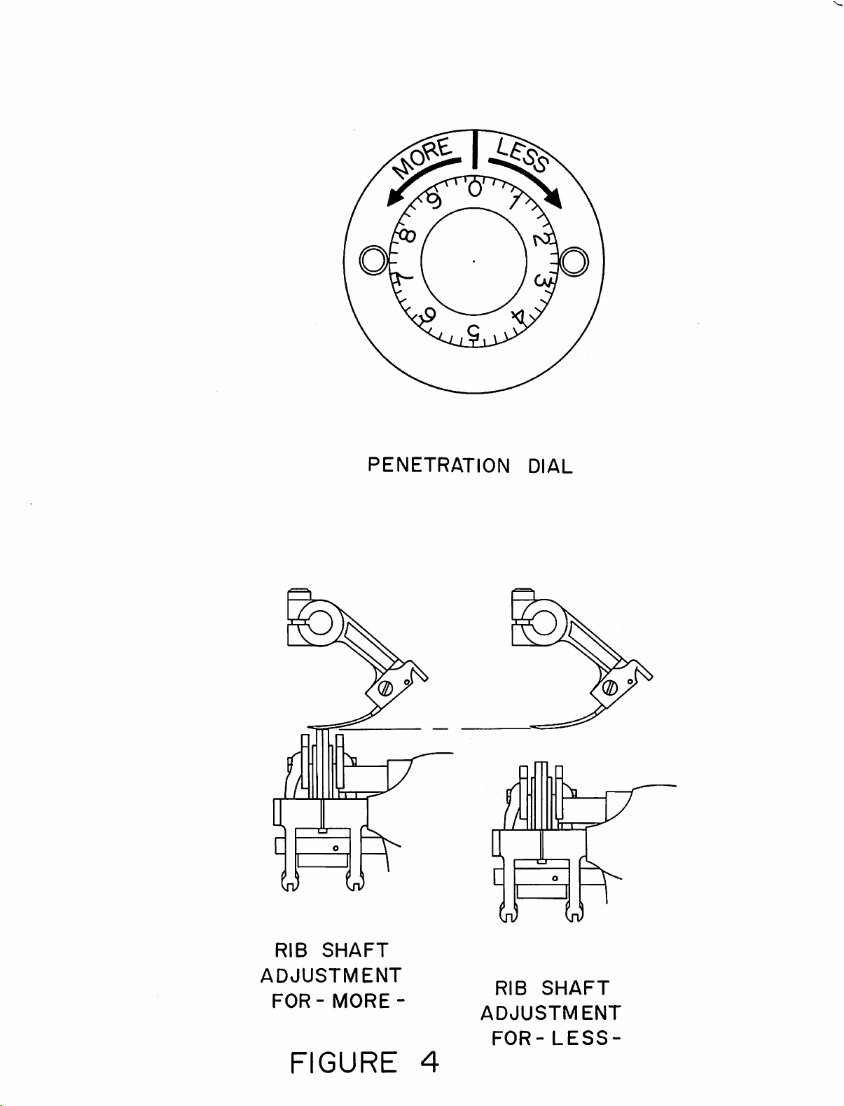
PENETRATION
DIAL
RIB
ADJUSTMENT
FOR
SHAFT
-
MORE
FIGURE
-
RIB
ADJUSTMENT
FOR-LESS-
4
SHAFT
enough,
the
alignment
turn
screw
of
the
in
opposite
lining
edge
direction
is
not
of
arrow.
correct,
If
then
H.
guide
if
going
ments
ADJUSTING
1.
This
rib
2.
This
Figure
ance
wrench.
counter
Item
there
from
are
SPRING
machine
which
adjustment
1,
hole
clockwise
"F"
is
an
a
required
can
which
of
Turn
should
extreme
tropical
LOADED
is
equipped
be
adjusted
is
is
the
cylinder
the
on
RIB
made
reached
screw
for
be
moved
fabric
to
a
the
-
with
by
clockwise
less
thickness
heavy
dial.
SERVICE
a
for
a
turning
through
using
tension.
to
correspond.
tweed,
MAN
spring
desired
screw.
the
a
1.5
for
ONLY
MM
more
This
change,
further
loaded
load.
Item
right
(.059)
screw
Naturally,
fall-away
hand
tension,
such
adjust
"D",
alien
has
as
clear
been
I.
sealed
However,
be
REPLACING
1.
U.S.
to
STITCH
designed
stitching,
U.S.
2.
When
needles,
a.
moved
THE
needles
meet
NEEDLES
it
Turn
in
place
after
and
will
NEEDLE
are
the
precise
MACHINES.
needle
it
is
be
becomes
the
following
the
penetration
with
locktite
overcoming
remain
designed
sewing
Because
in
achieving
extremely
used
at
necessary
the
in
place
and
requirements
of
important
all
times.
to
procedure
dial
and
may
initial
without
manufactured
the
importance
consistent
replace
should
to
the
be
hard
tightness,
of
high
that
worn
be
right
to
vibrating
specifically
the
U.S.
of
a
quality
only
or
GENUINE
damaged
followed:
("Less")
turn.
it
can
loose.
BLIND
properly
three
or
four
sufficiently
numbers
to
to
clear
insure
the
that
needle.
the
rib
is
lowered
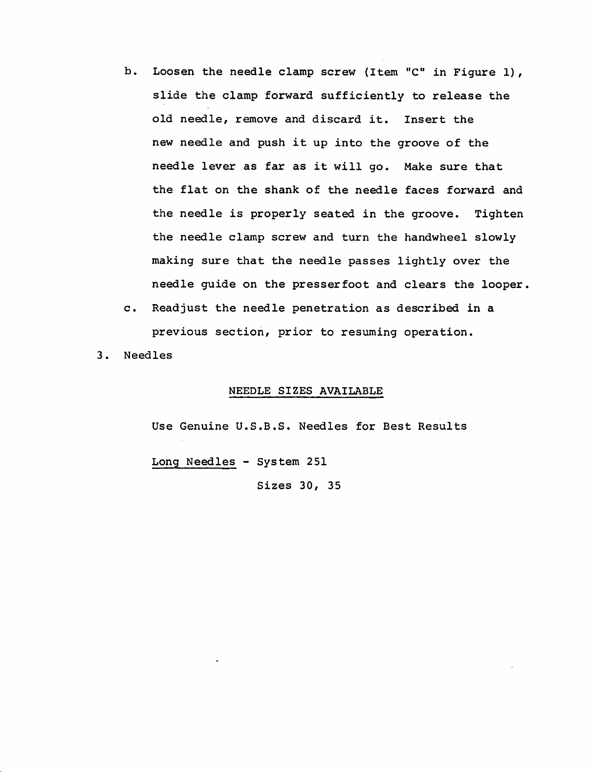
b.
Loosen
the
needle
clamp
screw
(Item
"C"
in
Figure
1),
slide
old
new
needle
the
the
the
making
needle
c.
Readjust
previous
3.
Needles
the
needle,
needle
lever
flat
needle
needle
sure
guide
clamp
remove
and
as
on
the
is
clamp
that
on
the
needle
section,
forward
push
far
shank
properly
screw
the
the
prior
sufficiently
and
discard
it
up
as
it
of
seated
and
needle
presserfoot
penetration
to
into
will
the
turn
passes
resuming
it.
the
go.
needle
in
the
the
and
as
to
release
Insert
groove
Make
faces
groove.
handwheel
lightly
clears
described
operation.
the
of
sure
forward
over
the
the
the
that
Tighten
slowly
the
looper
in
a
and
Use
Long
Genuine
Needles
NEEDLE
U.S.B.S.
-
SIZES
System
Sizes
AVAILABLE
Needles
251
30,
35
for
Best
Results

III.
MAINTENANCE
A.
REPLACING
1.
Should
in
Fig.
of
the
of
the
INSTRUCTIONS
THE
LOOPER
it
become
6)
do
foot,
needle
the
turn
is
necessary
following:
the
handwheel
in
the
to
middle
replace
with
clockwise
of
the
the
the
looper
foot
looper
at
until
opening.
(Item
the
the
"B"
left
point
2.
Loosen
the
looper
clockwise
reverse
Any
time
timing
absolutely
described
pass
the
over
loop,
looper
the
looper
the
the
a
and
slot,
looper
out
upside
above
looper
reset
essential
in
detail
the
and
and
is
clamp
approximately
down
if
and
procedure.
is
moved
necessary.
for
below,
needle
also
in
clear
needle.
at
the
position
screw
pull
correct
the
the
The
(Item
1/8
or
changed,
a
properly
correct
chain-off
first
where
of
out.
Proper
stitch
A,
Fig.
an
inch.
To
replace
recheck
looper
formation.
timed
position
pin,
check
the
looper
6)
looper
feeder,
point
and
Turn
the
timing
to
picks
the
pick
for
pull
looper
looper,
looper
is
As
will
up
timing
the
3.
thread
stroke.
prong
scarf
the
prong
1/64"
clears
In
the
crank
end
the
crank
loop
Referring
of
the
of
the
of
the
of
the
(.406MM)
the
chain-off
event
cam
cam
(Item
off
looper
needle,
needle
looper
clearance,
that
can
the.needle
to
should
approximately
should
pin
the
be
adjusted.
B,
Figure
Figure
eye.
and
(Item
timing
5)
during
7,
pass
At
pass
must
of
is
over
the
over
"D"
the
The
the
the
(Point
3/32"
same
be
in
looper
normal
timing
needle
"C"),the
and
just
(2.4MM)
time,
the
needle
so
set
Figure
return
clear
the
that
7).
must
setting
mark
long
behind
short
with
it
be
changed,
of
on
the
the
about
also
the

5
(Z)
FIGURE
5
FIGURE
6

cam
corresponding
to
the
notch
in
the
rim
of
the
feed
B.
eccentric
speed
it
movement
looper.
REPLACING
1.
After
wearing
groove
This
tration.
The
up
down
THE
considerable
to
condition
needle
Item
the
on
the
of
NEEDLE
action
form
When
guide
looper
the
C.
right
cam
of
on
can
this
was
Turning
on
will
GUIDE
service,
the
the
cause
happens
the
the
left
side
of
produce
it
needle
needle
thread
the
specifically
crank
the
may
will
guide
clockwise
side
breakage
foot.
a
reverse
be
cause
of
(Item
guide
designed
the
Reversing
expected
a
sharp
"G"
and
should
foot
action
in
uneven
be
as
will
and
that
edged
Figure
replaced
a
readily
the
of
slow
the
the
9).
pene
2.
replaceable
foot
from
Loosen
Figure
any
lint
old
guide
guide
foot
turn
is
and
the
operator
properly
been
introducted
the
the
needle
9)
and
or
and
seated
then
handwheel
and
under
wear
action
remove
dirt
insert
flush
retighten
check
the
plate
of
guide
the
that
may
the
with
in
the
to
insure
needle
between
to
prevent
the
needle.
attaching
worn
have
new
the
the
attaching
direction
and
the
damage
screw
needle
accumulated
guide.
top
that
the
that
guide
guide.
Insure
and
screw.
away
new
no
interference
and
(Item
side
the
to
under
of
from
guide
looper.
the
"A"
Clear
that
Slowly
presser-
in
the
the
the
the
fits
out
new
presser-
has
C.
REPLACING
1.
The
retainer,
in
shoe,
the
THE
event
SHOE
(Item
"E"
normally
of
wear due
in
will
Figure
not
to
8),
require
the
also
known
replacement.
particular
as
a
fabrics
cloth
However,
being

(^0
MORE
0)
FIGURE
ai
7
FIGURE
8

2.
used,
may
The
be
first
or
readily
if
step
the
shoe
replaced.
is
to
or
spring
loosen
the
suffers
complete
any
damage,
front
they
guide
3.
assembly
screw
pin
locking
shoe
Before
the
may
K
When
ment
out
worn,
pin
manner
be
and
replacing
shoe
excessive
by
(Item
(Item
removing
reinstalled
L.
Attach
properly
it
should
unscrewing
"A"
in
screw
"F"),
these
in
which
these
an
looseness.
be
Figure
(Item
shoe
components
the
in
the
old
shoe,
fits
replaced.
the
"B",
spring
items
the
front
8).
and
same
make
pin
In
guide
Next,
Figure
retaining
it
is
way.
to
the
sure
without
the
event
After
holder
loosen
8)
and
spring
is
advisable
assembled
Remove
new
shoe.
that
binding
that
replacing
the
slide
so
Items
the
the
attaching
shoe
out
(Item
to
that
H,
replace
and
pin
the
shoe,
the
"G").
note
it
J,
with
has
D.
shoe
and
the
sure
the
REPLACING
1.
After
replace
2.
Remove
chain-off
accumulated.
screw
is
against
pin
spring
"B",
Figure
shoe
presserfoot.
that
THE
is
the
CHAIN-OFF
considerable
the
the
chain-off
pin,
previously
the
and
8),
lined
up
shoe
chain-off
clean
Attach
removed.
side
shoe
and
check
with
clears
PIN
service,
pin,
pin
out
the
and
pin,
to
the
both
it
(Item
attaching
any
lint
new
chain-off
Insure
forward
retighten
insure
center
sides
of
of
may become
"D"
in
screw
or
dirt
that
edge
of
screws
that
the
the
necessary
Figure
and
that
pin,
the
the
(Items
the
center
rib.
opening
7).
remove
may
using
chain-off
slot
in
Also
have
the
the
"A"
of
in
of
to
the
pin
presserfoot,
and
then
tighten
the
screw.

(^RE
y
FIGURE
0
]
PW17
9
22
figure
10

E.
REPLACING
1.
In
the
THE
event
FEEDER
that
the
machine
develops
difficulty
by
2.
failing
frequently
service,
feeder
feeder
feeder,
(Item
attaching
may
then
under
Before
that
the
to
properly
especially
teeth
should
remove
"B"
in
screw
be
the
rear
tightening
feeder
found
have
Figure
slid
be
the
(Item
screw
is
feed
to
be
with
a
tendency
replaced.
front
9)
"C"
out
of
and
the
attaching
set
the
certain
and
place.
replace
to
the
cause.
In
feeder
loosen
in
the
work,
to
become
order
attaching
Figure
Insert
screws,
proper
After
hard
the
the
a
9).
worn
fabrics,
dull,
to
remove
rear
the
front
check
depth.
feeder
considerable
the
and
the
screw
feeder
The
old
new
feeder
screw.
to
Referring
is
the
old
feeder
see
to
Figure
below
all
the
and
light
setting
parallel
and
10,
parallel
and
dimensions
required
by
is.,established,
away
clears
both
tighten
"C")
from
the
sides
feeder
before
the
this
medium
should
to
are
intended
the
operator
looper
of
the
attaching
resuming
should
to
be
the
bottom
specific
rotate
(see
feeder
be
the
bottom
weight
fabrics.
approximately
of
as
guides
fabrics.
the
handwheel
and
check
Figure
slot
screws
sewing.
approximately
of
the
For
1/16"
the
presserfoot.
and
may
Once
slowly
to
insure
9,
Point
in
the
presserfoot.
(Figure
1/32"
presserfoot
heavy
(1.59
be
modified
the
proper
in
that
"H")and
9,
Items
(.795MM)
fabrics,
MM)
These
a
direction
the
also
"B"
for
below
as
depth
feeder
clears
Firmly
and
F.
THREAD
1.
The
TENSION
purpose
RELEASE
of
the
thread
tension
release
is
to
obtain

uniform
thread
tension
over
seams
and
vents.
This
tension
off.
thread.
should
wheel.
do
the
nut
Item
so
that
(using
and
counter
keep
locking
is
Turn
be
In
following
the
a
release
nut
A
felt
"K"
1/2
factory
the
handwheel
distinct
twice
the
event
(using
tension
open
clockwise
of
Item
adjusted
locking
referring
a
assembly
end
thread
"K".
with
a
minor
9/16
wrench)
for
to
if
necessary
when
clockwise
and
each
revolution
adjustment
to
Figure
open
can
clockwise
less
a
release.
minimum.
the
machine
as
releasing
end
wrench)
be
moved.
to
you
pull
of
of
must
3,
release
for
For
Retighten
reposition
is
the
the
be
just
Turn
more
best
sewed
on
thread
hand-
made,
locking
enough
Item
release
release
thread
the
"L"
results,
G.
TIMING
1.
2.
guide
OF
The
thread
3/8
of
(Figure
needle
foot.
If
an
directly
Open
alien
Item
turn
THREAD
an
inch
7).
stroke
adjustment
under
the
top
wrench
"N"
Figure
Item
RELEASE
should
This
window
through
from
is
the
"M"
moving
is
3,
(using
-
SERVICE
release
the
left
measurement
towards
needed,
release
plate,
the
opening
and
loosen
a
when
the
tension
looking
3/8
MAN
the
edge
is
the
open
ONLY
needle
of
to
the
tension
assembly
in,
in
unmarked
the
be
left
back
end
presserfoot
taken
side
lift
place
of
wrench).
is
located
when
of
cam
can
a
3/32"
the
screw.
the
the
located
be
reset.
machine.
Insert
the
same
and
hold
eye
of
presserfoot
the
3/32"
in
needle
place.
and
alien
tighten
is
wrench
Turn
in
the
line
screw.
into
the
handwheel
with
Check
the
marked
clockwise
right
the
screw,
edge
timing
until
of
of
loosen
the
the
the

thread
release
as
described
in
Paragraph
1.
If
the
needle
presserfoot
cam.
screws•
After
is
not
3/8
when
all
of
an
the
thread
adjustments
inch
from
is
are
the
released,
made,
edge
readjust
tighten
of
the
the
both

TO
MAINTAIN
PARTS
EFFICIENCY
CATALOG
OF
THE
ORIGINAL
EQUIPMENT
GENUINE
U.S.
PARTS
AND
NEEDLES
ARE
RECOMMENDED

1099SF/1200-SF
*5001
1401
5019
*1068
1069
5198
1005
1006
1093
1289
1240
1089
*1081
1096
1107
1054
1108
1080
1070
5197
MAIN
Side
Washer,
Screw,
Guard,
Screw,
Thread
Consists
1084
1083
1082
1329
1994
Tube,
Wick,
Screw,
Screw,
Pin,
Screw,
Plate,
Screw,
Screw,
Washer,
Screw,
Thread
Screw,
Thread
5217
1953-
1954
1959
1955-
1084
1957
1021-
1083
3046
1085
1011
3069
FRAME
Cover
GROUP
Assembly
Clamp
Side
Belt
Guard
Tension
of
Disc.
Oil
Oil
Set
Set
Presserfoot
Set
Top
Cover
Top
Cover
Bridge
Clamp
Clamp
Guide
Thread
Tension
Regulator
1
Rod
Spring
Nut
1
Sleeve
Thread
Post
6
Spacer
Disc
Disc
Spring
Ratchet
Nut
Screw
Cover
(for
:
Thread
Post,
Spring,
Nut,
Mtg.
Screw
Guide
(for
1200SF
Regulating
Guide
Thread
Thread
Tension
Tension
(for
Release
Ass'y
Guide
1200SF
only)
Ass'y.
Tension
Tension
1200SF
Ass'y.
only)
only)
*For
5182
7028
7004
the
1099SF
Side
Top
Belt
use
Cover
Cover
Guard
the
following
Assembly
Plate

51
97
51
ASS'Y
500
ASS'Y
98
ASS
1955-
1994
082
1084
I
1959
953-1
52
ASSY
7
Y
I
02
084
-6
1080
08
1096
006
§
I
068
MAIN
FRAME
GROUP

1099SF/1200-SF
***1964
5003-1*
5194-1*
*Sold
as
Main
Rib
Needle
an
Shaft
Connection
1974
1973
1880
1072
1134
1132
3061
3276
1946
Assembly
**The
(for
Screw
Screw
Screw,
Connection
Screw
Guard
Screw
Screw
Screw
Crank
Only
Following
1200SF
Lever
Eccentric
For
Stud
Clamp
Ass'y.
Optional
MAIN
only)
&
Eccentric
SHAFT
Handwheel
GROUP
Ass'y,
Ass'y.
1845
5226**
5232
5224
is
Available
Collar
1971
Handwheel
3290
3291
3032
Stitch
Regular
1834
Cam
Ass'y.
1814
Ass'y.
Screw
Handwheel
Screw
Pulley
Collar
Set
Screw
Ass'y.
1121
1069
Ass'y.
Screw
Screw
Ass'y.,
Screw
***For
7012-1
the
5188-1
1099SF
Main
use
Shaft
Handwheel
the
With
following;
Position
Hub

2 I
(2)
I I
I
072
32
34
(2I834
2
18
14
2
306
(2I072
5232
ASS'Y
5207
ASS'Y
5224
ASST
(2)1974
5003-1
%
ASS'Y
01
1069
o-(
e-
845
0
ASS
(2I97
ASST
(3)
3291
3290
3032
ASS'Y
5194-1
ASS'Y
MAIN
SHAFT
GROUP

1099SF/1200-SF
5184
Use
System
Needle
1076
3050
1945
1243
1944
Genuine
251
Lever
Screw
Screw
Clamp
Pin
Lever
U.S.B.S.
Size
NEEDLE
Ass'y.
NEEDLE
35
SIZES
or
DRIVE
Needles
Size
GROUP
5135
1095
AVAILABLE
For
40
for
Best
Heavy
Collar
Shaft
Results
Sleeves
1089
1118
Ass'y.
Screw
Screw

(2)1089
095
•5184
ASS'Y
3050
944
243
5 I
35
ASS'Y
ASS'Y
\
NEEDLE-SPECIFY
SIZE
REQUIRED
NEEDLE
DRIVE
GROUP

1099SF/1200-SF
5212
1834
5023
1821
2124
FEED
Feed
Screw
Feed
Thrust
Feeder
Lever
(Sold
Rocker
1870
1119
DRIVE
Collar
&
as
Set
Feeder
GROUP
Stitch
Ass'y.
Ass'y.
Ass'y.
Screw
Screw
Collar
only)
Ass'y.

5212
ASSV
(2)1834
5232
AS
AS
_
ST
ST
ASST
(2)
2
24
I I
19
FEED
DRIVE
GROUP
(2
1870
ASSY

1099SF/1200-SF
Part
2203
1150
5233
5195
5213-1
5186-1
5206-1
No.
LOOPER
Description
Looper
Stud,
Collar
1870
Looper
Consists
1154
1155
3049
1979
3297
1094
Looper
Consists
5185-1
1154
3049
1979
Looper
Consists
5017
1117
5185-1
Looper
Consists
5186-1
1154
3049
1979
DRIVE
Looper
Ass'y.
Set
Rod
of
Fork
Pin
Screw
Nut
Stud
Screw
Rod
of:
Looper
Fork
Screw
Nut
Rod
of
Looper
Screw
Looper
Rod,
of:
Ass'y.
Fork
Screw
Nut
GROUP
Adjustment
Screw
Fork,
:
&
Fork
&
Carrier
;
Fork
Sleeve
Ass'y.
Rod
Rod
Rod
&
&
Ball
Ass'y.
Carrier
&
Ball
Carrier
&
Stud
Ass'y.
Ass'y.
Ass'y.
Ass'y.
Ass'y.

ASS
2
094-
3297
ASST
5195
870
Y
5186-1
ASS'Y
1870
835
ASS'Y
3049
LOOPER
DRIVE
GROUP

1099SF/1200-SF
*5046-1 Feed Frame
1836-1
5167
*1205
*1030
3057
1262
2434
1244-4
1146
1966
1167
1836
6098
Collar
1077
Rib
1117
Plate,
Screw,
Post,
Nut
Platten,
Screw,
Nut
Screw,
Nut,
Collar
1079
Rib
2086
1158
1881
*6095
Ass'y.
Shaft
Window(for
Plate(for
Spring
L.H.
Platten
Cylinder
Platten
Ass'y,
Set
Shaft
Ass'y.(for
Set
Screw
Crank
Screw
Lock
Screw
Pawl
Rib
Pawl
Screw,
Nut
Rib
Shaft
(for
1200SF
Ass'y.
1200SF
Ass'y
Pawl
1200SF
1200SF
Ass'y.
only)
FEED
only)
only)
FRAME
only)
GROUP
2483
2484
1379
1069
1021
3062
1710
3056
2435
1113
*1213
*1066
3027
1004-1
3280
3065
3063
3059
3058
3064
I
BKT,
BKT,
Stud
Set
Spacer
Spring
Screw,
Post
Platten,
Screw,
Cylinder(for
Shaft,
Plate
Stud
Set
Spring
Spring
Retaining
Yoke
Retaining
L.H.
R.H.
Screw
:-1021-l
Cover
Screw
Platten
Platten
12
Limit
R.H.
Frame
Rocker(for
Pin
Ring
Ring
=
=
1200SF
.010";
.015",
only)
1200SF
etc.
only)
*For
5179
7019
1864
1099SF
Feed
Window
(2)
use
Plate
the
Frame
Plate
following;
Ass'y.
Screw
7014
1213-1
8095
Rocker
Cylinder
Rib
Shaft
Shaft
Ass'y.

5167
ASS
Y
836
ASS'Y
(2)1244-4
2434
(2)1167
(2)3062
(2)
1262
3056
6098
ASS
Y
(2
3059
1205
3
1966
1069
1079
3064
1030
(2)1004-1
1836-
ASS
1077
Y
(2)1710
1066
FEED
FRAME
GROUP
5046-1
I
ASS'Y—J

1099SF/1200-SF
5020
1146
1177
1184
1191
5235
7013
3079
4544
5237
1882
3047
1117
1271
1393
1414
1839
1879
1008
1117
FEED
FRAME
Spring
1176
Nut,
Screw,
Nut,
Main
Knee
1208
1037
Key
Knee
Pad,
Knee
1841
3048
1815
3299
1054
Washer
Block
Screw
Knee
Screw
Washer
Bracket
Screw
Nut
Screw
GROUP
Link
Ret'ng,
Link
Spring
Spring
Pedal
Lift
Pedal
Lifter
Lifter
Ass'y.
Pin
Ass'y.
Knee
Screw
Rod
Bracket
Screw
Link
Bracket
Screw
Washer
Spring
II
Pedal
(For
Ass'y.
3299
Screw)

70
I 3
REAR
OF
MAIN
WALL
FRAME
3047
5046-1
ASS'Y
5020
ASS'Y
3079
4544
MAI
FRAME
1117
I
177
1879
I
176
008
1841
5237
/
ASS'Y
N
1839
(21414
(2)1
393
20^
FEED
FRAME
GROUP
5235
n
ASS'Y

1099SF/1200-SF
1186
5012-1
1025
5018
*For
5173
5178
1977
REGULATING
Regulating
Push
Pin
Regulator
the
1099SF
Dial
Dial
Screw
Rod
1023
1024
1109
*5039
*5010
1223
1222
*1039
&
Ratchet
Plate
Ass*y.
Pin
Spring
Screw,
Dial
Dial
Shoe
Screw
Screw
use
Ass'y.
GROUP
Fork
Ass'y.
the
Ass'y.
-
Regulator
&
Ratchet
Plate
(for
following;
Complete
Ass'y.
Ass'y.
1200SF
(for
only)
(for
1200SF
1200SF
only)
only)

1223
,5010
5018
ASS'Y
ASS'Y
5039
AS
U039
(2)1
ST
109
REGULATING
GROUP
501
ASS'Y
2-1

1099SF/1200-SF
5214
1099
1943
1967
2620
1079
1237
1106
6194
1054
1108
1107
PRESSERFOOT
Shoe
Ass'y,
1075
1372
1308
1305
2542
Screw
Spring
Bracket
Edge
Screw
Pin
Set
Guide
Screw
Presserfoot
1866
1961
1102
1960
Washer
Screw
Screw
ASS'Y.
Screw
Lock
Screw
Spring
Shoe
Ass'y.
Screw
Pin,
Screw
Guide
Spring
Chain
Off

-5214
1075
1372
1099
cfT
I960
2
6
194
ASSY
1054
1967
1079
COMPLETE
PRESSERFOOT
ASS'Y
5259
GROUP
(2)I107

Notes

A
MachineisOnly
as
Good
as
its
NEEDLE!
with
wash
U. S.
recognition
in
foremost
unequalled.
and
quality
saved
U. S.
top-quality
and
and
on
inferior
specifications
needlesisthe
curvature
Don't
Top-quality
Peak
wear
in
fabrics
performance.
Imitations
U.
S.
The
quality
and
cannot
our
products.
For
durability
Their
assure
Take
sewing
needles
efficiehcy
is
or
needles
Blind
Stitch
of
the
of
be
knowledge
uniform
efficient,
Chances—Avoid
demands
to
achieve
in
today's
accomplished
substitutes
only
prove
needles
finest
U. S.
duplicated.
and
construction,
perfect
high-speed
areacostly
to
be
are
materials
Needles
The
that
freedom
economical
only
quality
from
Trouble
top-quality
results.
with
expensive
made
and
workmanship
is,infact,amatter
confidence
is
breakage,
carefully
stitching.
machines
sewing
needles
compromise.
dollars
in
the
United
of
our
and
always
U. S.
controlled
of
synthetic
of
superior
in
the
available.
of
customers
has
equipped
Pennies
long
States
world-wide
been
Needles
finish
and
run.
to
are
BE
SURE
GENUINE
Lo(dc
on
The
perfection exists in all
BE
fot
all
TO
U.
fhk
parts
S.
USE
ONLY
NEEDLES
U6e/
same precision construction and working
U.
S. Machine Parts.
SURE
TO
GET
U.
S. —
ACCEPT
NO
GENUINE
U.S.
NEEDLES
U.S. BUND
MACHINE
Express
and
Plainview,NewYork 11803
Made
Skyline
In
STITCH
CORP.
Street
Drive
U.S.A.
SUBSTITUTE
500/885
PREVTON,
LITHO
U.S.A.
 Loading...