


U S Blindstitch 1099LP, 1099LP-1, 1099PB, 1099PB-1, 1099PBT User Manual
...
U.S.
BLIND
STITCH
EXPRESS
MACHINE
STREET
&
SKYLINE
CABLE
ADDRESS:"BLINSTIT
1099
COVERING
STANDARD
DRIVE
TELEPHONE:
1099LP
1099LP-1
1099PB
COHP.
PLAINVIEW
PLAINVIEW
SERIES
THE
SUB
FOLLOWING
CLASSES:
N.Y.
11803
516-433-4350
NEW
YORK"
1099PB-1
1099PBT
1099PBW
U
r-';
S,
Mi
I
MAINTENANCE
PARTS
©
1979•U.S.
CATALOG
BLIND
STITCH
MACHINE
<&
m
CORF.
ni-MAINTENANCE
INTRODUCTION
FOR
1118,1099
INSTRUCTIONS
&
1108
SERIES
A. Replacing
B. Replacing
C. Replacing
D. Replacing
the
Looper
the
Needle Guide
the
Shoe
the
Feeder
MAINTENANCE
INTRODUCTION
INSTRUCTIONS
All U.S. BLIND STITCH machines are designed for long life and trouble-free performance. When
installed
and
lubricated
in
accordance
with
the
INSTALLATION
AND
OPERATING
INSTRUC
TIONS, only the minimum maintenance normally associated with industrial sewing machines will
be required. These maintenance requirements will generally be
cribed
worn
tion, and to insure satisfactory service, it is essential
and needles are used. They are
in long life
below,atwhich
part
may
be readily
and
excellent wearing characteristics typicalofthe
A.
REPLACING
wear
maybeexpected
replacedbyfollowing
the
only
parts designed specifically
THE
LOOPER
after
the
extended
appropriate
that
confinedtothe
use. When
instructions.
such
four
locations des
wear
does
For
easeofinstalla
occur,
the
only genuine U.S. BLIND STITCH parts
for
the
machine, with
the
built-
U. S. BLIND STITCH machine.
1. Should it become necessary to replace the looper (item
loosen
looper. Becauseofthe
necessarytoexertamoderate
the new looper
the
the
looper
looper
clamp
into
shoulder.
screw
(item
"A"
precise fitofthe looper in
amountofforcetopull
the endofthe
rod as far as it will go before
in Figure 6)
the
"B"
and
looper
the
in Figure 6),
remove
looper
rod
the
it may be
out.
bottoming
old
Insert
2. Any time a looper is moved or changed, recheck the looper timing and reset
if
necessary.
formation. As described in detail below, a properly timed
over
the
chain-off pin, feeder, looper slot, and needle. The first check
the
looper
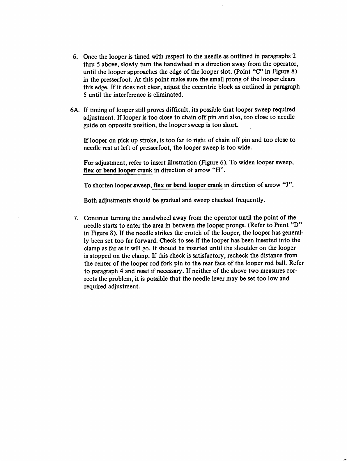
needle during the needle return stroke. Referring to Figure 7, (Point
the
long
needle, approximately
the
same time,
about
chain-off
Proper
needle in
looper
the
timing is absolutely essential
correct
positiontopickupthe
is at the position where the looper picks
prongofthe
1/64"
(.406mm)
pin
(item
the
looper
3/32"
short
"D"
should
(2.4mm)
prongofthe
clearance,
in Figure 7).
pass over
behind
looper
and
must
and
the
should
be so
for
loop,
the
thread loop
just
clear
endofthe
pass over
set
that
correct
looper
and
will pass
also clear
point
stitch
for timing
off
the
scarfofthe
needle eye. At
the
needle
it also clears
the
the
"C"),
with
the
on
3. To adjust the looper so that the timing checks out as noted in paragraph 2,
it may be rotated within its clamp by a limited amount. This adjustment
should be made with the looper clamp screw (item
and the looper bottomed against its shoulder. Do
out, and do
amount
4.
If
the adjustment described in paragraph 3 is insufficient to provide
of
not
travel
attempt
available.
to force the loopertoturn beyond the limited
timing, it willbe necessary to turn the looper rod (item
"A"
in Figure 6) loosened,
not
move the looper in or
"E"
in Figure6) itself.
the
correct
Thismay be accomplished by loosening with looper rod clamp screw (item
in Figure6). The rod is then free to turn in the looper rod fork (item
"D"
Figure 6). It will normally be necessary to make only a very small adjustment
in order to get the looper into the correct rotational position for proper timing.
If, for any reason,
rod
has
been
distance from
the rear face of the looper rod ball (item
the
rod has been removedorthe
disturbedbya large
the
centerofthe
basic settingofthe
amount,itmayberesetbynoting
looper
rod
fork
pin (item
"G"
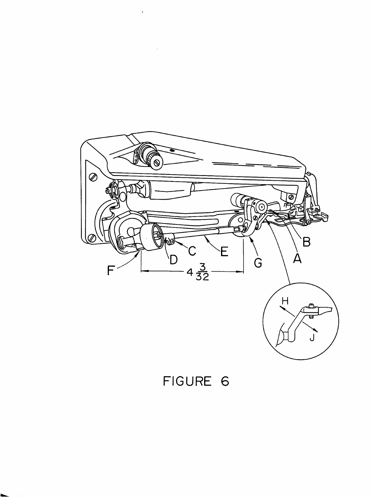
in Figure 6) is normally 4 & 3/32
"F"
looper
that
in Figure 6)
inches (104mm) (refer to Figure 6). If the rod is set to this dimension then only
minor
position. Note
variations
adjustment
that
maybeexpected
will be requiredtobring
the
looper
into
the
correct
timing
this dimension is merely a guidetoassist in setting a rod and
from
machinetomachine.
"C"
in
the
to
5. If, after completing the above adjustments, it is found
too
low or
the
two
slotofthe
raise or lower the
too
high, it will be necessarytoadjust
set
screws (item
eccentric
stud
looper
"A"
in Figure 7). Place a wide blade screwdriver in
(item
"B"
in Figure 7) and, using a slight turning
as required. Once
the
proper
that
the looper is either
the
eccentric stud. First loosen
height is established, check
to see whether the looper must be moved to the left ortothe right prior to retight-
ening the eccentric block set screws. If such a movement is required, it may be ob
tained by lightly tapping the eccentric block in the correct direction with the
handle
ofascrewdriver.
the
motion,
0
0
\
FIGURE
6
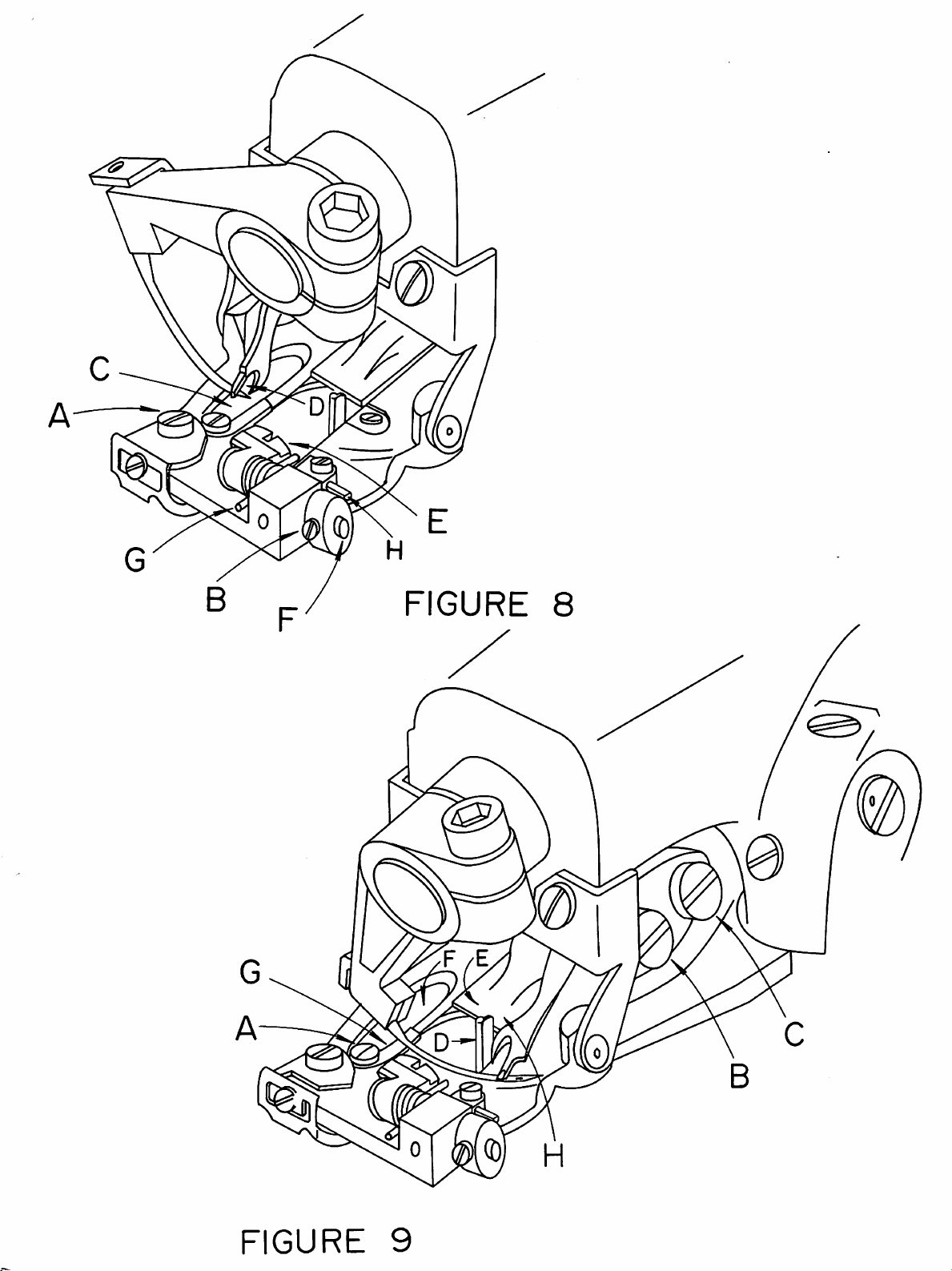
6. Once the looper is timed with respect to the needle as outlined in paragraphs 2
thru
5 above, slowly
until the looper approaches the edgeofthe looper slot. (Point
turn
the
handwheel in a direction away from
the
"C"
in Figure 8)
operator,
in the presserfoot. At this point make sure the small prongofthe looper clears
this edge. If it does
5
until
the
interference
not
clear, adjust the eccentric block as outlined in paragraph
is
eliminated.
6A. If timingoflooper still proves difficult, its possible
adjustment. If looper is too close to chain
guide on opposite position,
If looper on pick up stroke, is
needle
For
restatleftofpresserfoot,
adjustment, refertoinsert illustration (Figure 6). To widen
the
looper
too
far to rightofchain
the
sweep is
looper
off
sweep is
flex or bend looper crank in directionofarrow
that
looper sweep required
pin and also, too close to needle
too
short.
off
too
pin and
wide.
too
looper
"H".
To shorten looper.sweep,flex or bend looper crank in directionofarrow
Both
adjustments should be gradual and sweep checked frequently.
the
7. Continue turning
needle starts to
handwheel away from
enter
the area in between the looper prongs. (Refer to Point
the
operator
until
the
pointofthe
in Figure 8). If the needle strikes the crotchofthe looper, the looper has general
ly been set too far forward. Check to see if the looper has been inserted into the
clamp as far as it will go. It should be inserted until
the
shoulder on the looper
is stopped on the clamp. If this check is satisfactory, recheck the distance from
of
the center
to
paragraph 4 and resetifnecessary. If
rects
the
required
the looper rod fork pin to the rear faceofthe looper rod ball. Refer
problem, it is possible
adjustm.ent.
neitherofthe
that
the needle lever
above
may
two
be set
measures
too
low and
close
sweep,
"J".
to
"D"
cor
FIGURE
7
8. Once clearance is established between the needle and the looper crotch,
continue
passes between the
If
difficulty is experienced at this
of
the
If
this is
lished
turning
the
handwheel away from
looper
prongs, clearing
previous adjustments to
done,
which
recheck
will satisfy allofthe
the
previous
the
both
point,itmay
the
eccentric block or the
pointstoinsure
clearance
conditions.
operator
the long and the
until
the
short
be necessary to modify some
looper
that
a position is estab
rod
9. After all the necessary adjustments have been made, tighten all set screws and
the
lock
nut
and
B.
recheck all
looper
("F"),
loop.
REPLACING
1.
After
needle will cause a sharp edged groovetoformonthe
in
This
happens
ed as a readily
the
should
needle,
considerable
Figure
9).
condition
the
action
now
and
THE
guide
replaceable
of
the
clear
pass over
NEEDLE
service,itmaybeexpected
can
cause
should
needle.
the
adjustment
the
chain-off
the
needle in
GUIDE
thread
breakage
be replaced.
wear
platetoprevent
points. Referring to Figure 9, the
pin
("D"),
the
and
The
feeder
("E"),
looper
correct position to pick up
that
the
wearing
needle guide
uneven
needle guide was specifically design
penetration.
damagetothe
actionofthe
presserfoot
needle
prong.
length.
slot
(item
When
the
"G"
this
from
C.
2. Loosen
worn
the
with
Slowly
to
ference
REPLACING
1.
The
not
fabrics being
readily
2. The first
front
the
needle guide
needle guide. Clear
old guide
the
insure
shoe, (item
required
and
top
and
turn
the
that
the
has
been
THE
replacement.
used,orif
replaced.
handwheel in
introduced
SHOE
"E"
stepisto
guide
holder
attaching
out
insert
the
new guide. Insure
sideofthe
new guide fits
screw (item
any
lintordirt
presserfoot
the
and
direction away from
properly
between
the
in Figure 8), also known as a
However,inthe
the
shoeorspring suffers
remove
the
complete
attaching screw (item
front
"A"
pin and the shoe eccentric barrel lock screws, (item
the
shoe
pin
(item
"F"),
shoe
and
retaining spring (item
these
components
bledsothatitmaybereinstalled in
it is advisabletonote
the
the
same
"A"
in Figure9)and
that
may
have
accumulated
that
the
new
guide is seated flush
then
retighten
under
guide
the
and
needle
the
cloth
eventofwear
any
the
attaching
the
operator
and
thatnointer
looper.
retainer, normally will
duetothe
damage,
they
guide assembly by unscrewing
in Figure 8). Next loosen
"B"
Figure 8), and slide
"G")-
Before removing
manner
way.
in which the spring is assem
remove
under
screw.
and
check
particular
may
be
the
shoe
the
the
out
e
FIGURE
8
FIGURE
9