

ILS.BLIIII
STnCH
EXPRESS
MMHME
STREET&SKYLINE
CABLE
ADDRESS:"BLINSTIT
1099
COVERING
STANDARD
DRIVE
1099-CS
1099-CS-I
1099-9
I099-DP
PLAINVIEW
TELEPHONE:
PLAINVIEW
SERffiS
THE
SUB
1099-G
CUR
N.Y.
11803
516-433^350
NEW
YORK"
FOLLOWING
CLASSES:
I099-FP
I099-FP-1
I099-KS
I099-KS-I
MAINTENANCE
PARTS
© 1979• U.S. BLIND STITCH MACHINE CORP.
CATALOG
&
ifWMAWc
ni-MAINTENANCE
INTRODUCTION
FOR
1118,1099
INSTRUCTIONS
&
1108
SERIES
A. Replacing
B. Replacing
C. Replacing
D. Replacing
the
the
the
the
Looper
Needle
Shoe
Feeder
Guide
MAINTENANCE
INTRODUCTION
INSTRUCTIONS
All U.S. BLIND STITCH machines are designed
installed
TIONS,
be required. These
cribed below, at which wear
worn
and
only
lubricated
the
minimum
in
accordance
maintenance
maintenance
requirements
maybeexpected
part
may be readily replaced by following
with
normally
for
the
INSTALLATION
will generallybeconfinedtothe
after
the
tion, andtoinsure satisfactory service, it is essential
and needles are used. They are
in long life
A.
and
excellent wearing characteristics typicalofthe
REPLACING
1.
Shoulditbecome
loosen
looper.
THE
the
Becauseofthe
necessarytoexertamoderate
the
new
looper
the
looper
2.
Any
timealooperismovedorchanged,
if
necessary.
formation.Asdescribedindetail
over
the
needleinthe
chain-off
the
pin,
looperisat
needle during
the
long
prongofthe
needle,
the
about
chain-off
approximately
same time,
1/64"
pin
the
LOOPER
looper
clamp
into
shoulder.
Proper
feeder,
the
the
needle
the
(.406mm)
(item
only
parts designed specifically for
necessarytoreplace
screw
(item
precise
fitofthe
amountofforcetopull
the
endofthe
looper
correct
looper
position
looper
3/32"
short
clearance,
"D"
in Figure
timingisabsolutely
return
prongofthe
rodasfarasit
below,aproperly
positiontopickupthe
slot,
and
where
the
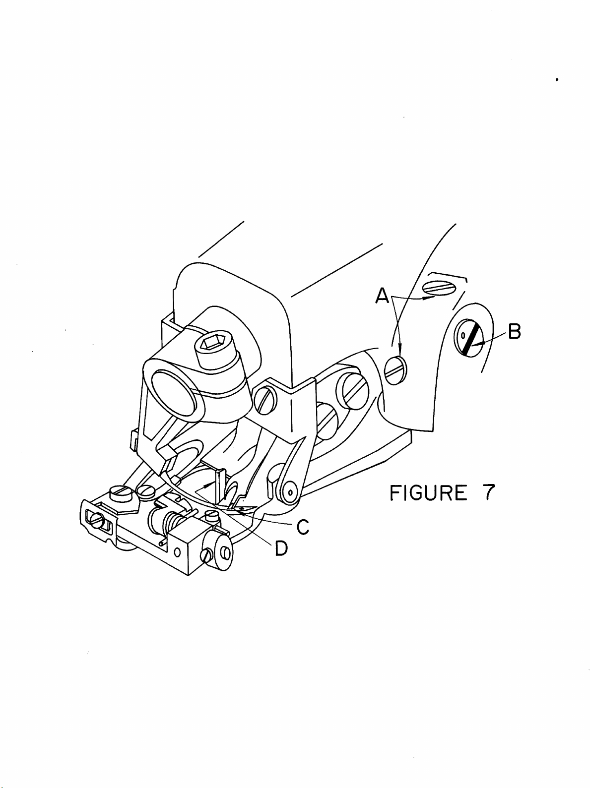
stroke. Referring to Figure 7,
should
(2.4mm)
and
7).
long life
associated
extended
and
trouble-free performance. When
AND
OPERATING
with
industrial
use. When
appropriate instructions.
that
only
genuine U.S. BLIND STITCH
the
U. S. BLIND STITCH machine.
the
looper
"A"
in Figure6)and
looperinthe
(item
looper
"B"inFigure
the
recheck
will go
the
essential
before
looper
for
timed
loop,
needle.
looper
pass
behind
looper
must
over
be so set
The
picks
and
the
should
first
check
the
thread
just
clear
endofthe
pass
over
thatitalso clears
sewing
four
such
wear does occur,
For
easeofinstalla
machine, with
remove
looper
the
roditmay
out.
bottoming
timing
correct
looper
and
will pass
also clear
point
loop
and
stitch
for
off
(Point
the
scarfofthe
needle eye.
the
needle
INSTRUC
machines
locations
the
6),
old
be
Insert
on
reset
the
timing
the
"C"),
At
with
the
will
des
the
parts
built-
3. To adjust
it
mayberotated
should be
and
out,
amount
the
made
the
looper
anddonot
of
travel
loopersothat
within
with
bottomed
attempttoforce
available.
its
the
looper
against its shoulder. Do
the
timing checks
clamp by a limited
clamp screw (item
the
loopertoturn
outasnoted
amount.
not
This
"A"
in Figure6)loosened,
move
beyond
in paragraph 2,
adjustment
the
the
looper
limited
in or
4. If the adjustment described in paragraph 3 is insufficient to provide the correct
timing,itwill be necessarytoturn
This
maybeaccomplishedbyloosening
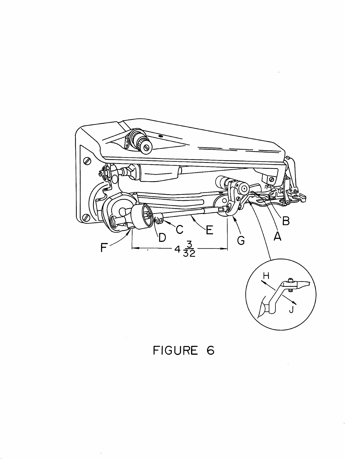
in Figure 6). The
rodisthen
free to
the
looper
turn
rod
(item
with
looper
rod
in the looperrod fork (item
"E"
in Figure 6) itself.
clamp
screw
(item
"D"
"C"
in
Figure 6). It will normally be necessary to make only a very small adjustment
to
in order
get thelooper
If, for any reason, the rod has been removed or the basic setting
rod has been disturbed by a large amount,itmay be reset by noting
distance from the centerofthe looper rod fork pin (item
the
rear faceofthe
looper
into
the correct rotational position for proper timing.
of
the looper
"F"
in Figure 6) to
rod
ball (item
"G"
in Figure 6) is normally 4 &
that
the
3/32
inches (104mm) (refer to Figure 6). If the rod is settothis dimension then only
minor adjustment will be required
position. Note
variations
that
this dimension is merely a guidetoassist in setting a
maybeexpected
from
to
bring the looper into the correct timing
machinetomachine.
rod
and
5. If, after completing the above adjustments, it is found
too
lowortoo
the
two
set
slotofthe
raise or lower
to see
whether
high,itwill be necessarytoadjust
screws
eccentric
the
the
(item
stud
looper
looper
"A"
in Figure
(item
"B"
in Figure 7) and, using a slight turning
as required. Once
must
be movedtothe
7).
Place a
the
proper
that
the looper is either
the
eccentric
wide
blade screwdriver in
stud.
height is established, check
leftorto
the
right
priortoretight-
First
ening the eccentric block set screws.Ifsuch a movement is required, it may be ob
tainedbylightly
handle
ofascrewdriver.
tapping
the
eccentric
blockinthe
correct
direction
with
loosen
the
motion,
the
0
\
FIGURE
6
6. Once
the
looper
thru
5 above, slowly
until
the
looper
in
the
presserfoot. At this
this edge. If it does
5
until
the
is timed with respect to
turn
the
approaches
point
not
clear, adjust
interference
is
eliminated.
handwheel
the
edgeofthe
make
the
needle as outlined in paragraphs 2
in a direction away from
sure
the
looper
the
eccentric
slot. (Point
small
block
prongofthe
the
operator,
"C"
in Figure 8)
looper
clears
as outlined in paragraph
6A.Iftimingoflooper
adjustment. If looper is
guide on opposite position,
If
looperonpickupstroke, is
needle
For
restatleftofpresserfoot,
adjustment,
flexorbend
still proves difficult,
too
refertoinsert
looper
crank
its
possible
closetochain
the
looper
too
fartorightofchain
the
illustration
sweep is
looper
off
sweep is
(Figure
in directionofarrow
that
pin
and
too
short.
6).Towiden
"H".
also,
too
looper
off
wide.
too
pin
To shorten looper.sweep, flex or bend looper crank in directionofarrow
Both
7.
Continue
needle
in Figure 8). If
ly
been
clamp as
is
stopped
the
centerofthe
to
paragraph4and
rects
required
adjustments
turning
startstoenter
set
too
far
on the clamp. If this check is satisfactory, recheck
the
problem,
adjustment.
should
the
handwheel away from
the
the
needle strikes
far
forward.
as it will go. It
looper
rod
resetifnecessary.Ifneitherofthe
it is possible
be gradual
and
area in between
the
crotchofthe
Checktoseeifthe
shouldbeinserted
fork
pintothe
that
the
sweep
the
checked
the
operator
looper
looper
until
rear
faceofthe
needle lever
frequently.
until
prongs.
looper,
the
the
has
been
shoulderonthe
looper
above
maybeset
(RefertoPoint
two
sweep required
closetoneedle
and
too
close
looper
the
looper
inserted
the
too
sweep,
pointofthe
has general
into
looper
distance from
rod
ball. Refer
measures
low
and
to
"J".
"D"
the
cor
FIGURE
7
8. Onceclearance is established between the needle and the looper crotch,
continue
passes between the looper prongs, clearing
turning
the
handwheel away from
the
operator
both
the long and the
until
the
short
If difficulty is experienced at this point, it may be necessary to modify some
of
the previous adjustments to the eccentric block or the looper rod length.
If this is done, recheck
lished
which
will satisfy allofthe
the
previous
points
clearance
to insure
conditions.
that
a position is estab
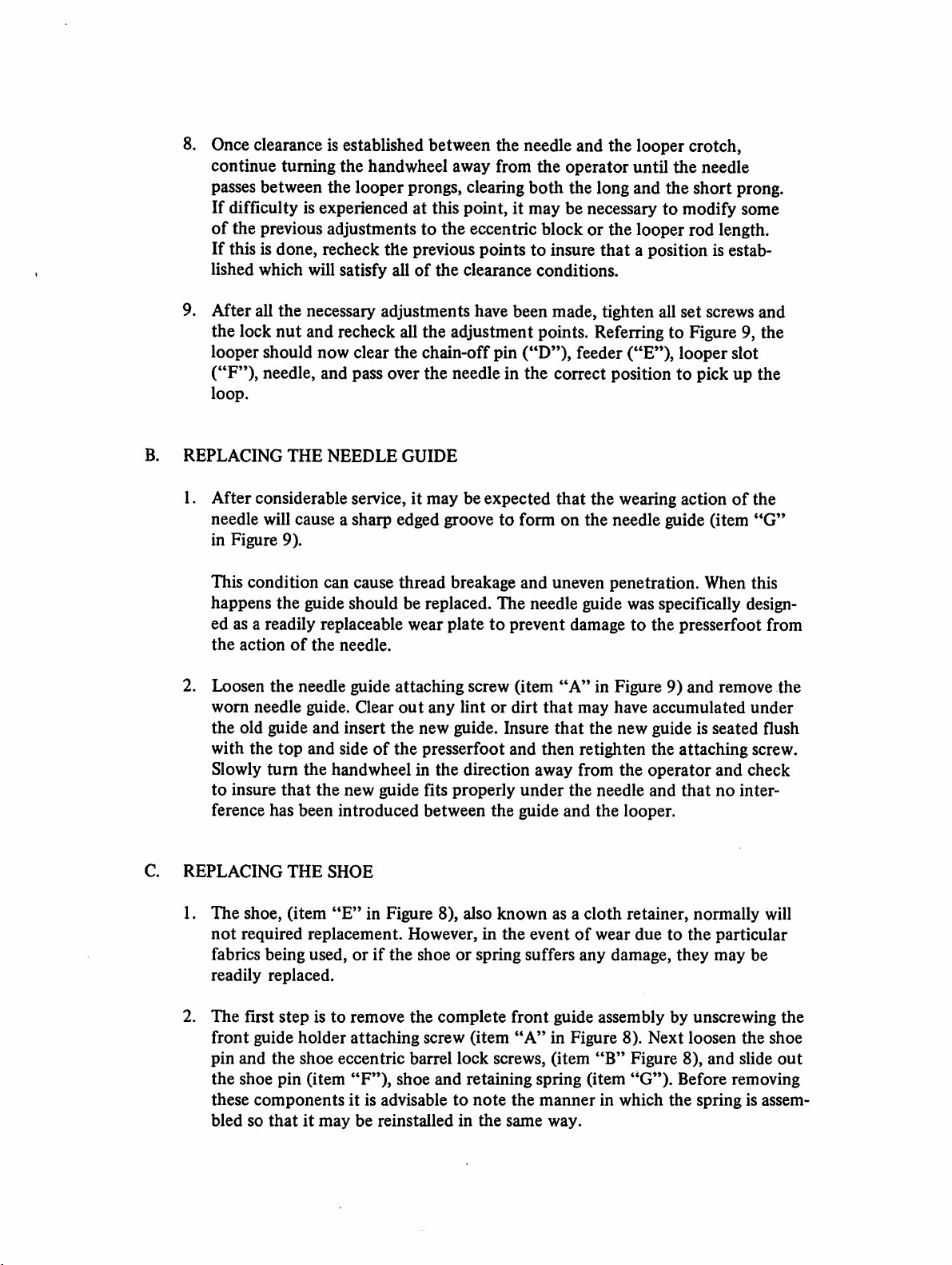
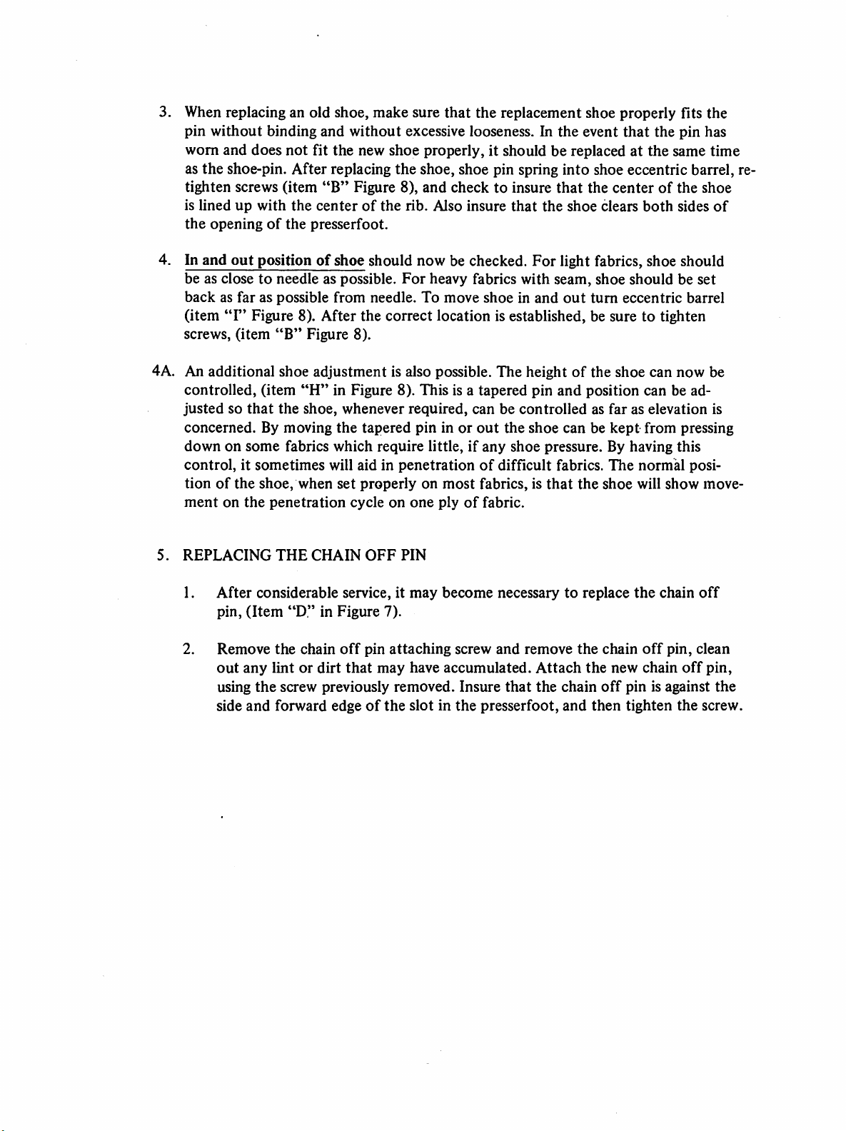
9. After all the necessary adjustments have been made, tighten all set screwsand
nut
and recheck all the adjustment points. Referring to Figure 9, the
should
now
clear
the
chain-offpin
("D"),
feeder
("E"),
looper
needle, and pass over the needle in the correct position to pick up the
THE
NEEDLE
GUIDE
B.
the lock
looper
("F"),
loop.
REPLACING
needle
prong.
slot
1. After considerable service, it may beexpected
needle will cause a sharp edged groove to form on
in
Figure
9).
This condition can cause thread breakage
that
the wearing actionofthe
the
needle guide (item
and
uneven penetration. When this
happens the guide should be replaced. The needle guide was specifically design
ed as a readily replaceable wear
the
action
2. Loosen
worn
the
old guide and insert
with
Slowly
to
insure
ference has
REPLACING
1.
The
not
required
fabrics being used,orif
readily
of
the
needle.
the
needle guide attaching screw (item
needle guide. Clear
the
top
and
sideofthe
turn
the
handwheel in the direction away from
that
the
new
been
introduced
THE
SHOE
shoe,
(item
"E"
replacement.
replaced.
in Figure
out
the
guide fits
the
platetoprevent damagetothe
"A"
any
lintordirt
new guide. Insure
presserfoot
properly
between
8),
However,inthe
shoeorspring suffers
the
also
that
and
then
under
guide
known
eventofwear
may
that
retighten
the
and
as a
any
presserfoot from
in Figure 9) and remove the
have
accumulated
the
new guide is seated flush
the
attaching screw.
the
needle
the
cloth
operator
and
looper.
retainer,
duetothe
damage,
and check
thatnointer
normally
particular
they
may
"G"
under
will
be
2.
The
first
step
is to remove
front
guide
holder
pin
and
the
shoe
the
shoe
pin
(item
these
components
bledsothatitmay
attaching
eccentric
"F'*),
it is advisabletonote
be reinstalled in
the
barrel
shoe
complete
screw
lock
and
front
(item
"A"inFigure
screws,
retaining
the
the
same
guide assembly by unscrewing
(item
spring
mannerinwhich
way.
"B"
(item
8).
Next
Figure 8),
"G*').
the
loosen
Before
the
and
slide
removing
spring is assem
the
shoe
out
e
F
CURE
8
FIGURE
9
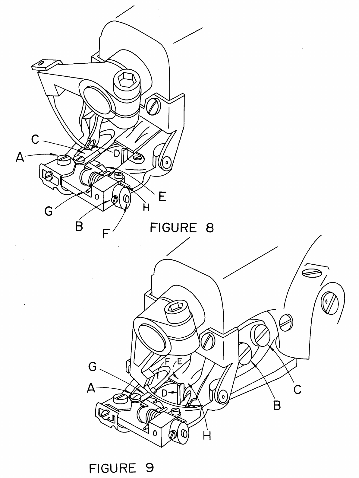
3. When replacing an old shoe, make sure
pin
without
worn and does
as
the
tighten
is
linedupwith
the
openingofthe
binding
shoe-pin.
screws
and
without
not
fit the new shoe properly, it should be replaced at
After
replacing
(item
"B"
Figure 8),
the
centerofthe
presserfoot.
excessive looseness. In
the
shoe, shoe pin spring
and
rib.
that
the replacement shoe properly fits the
checktoinsure
Also
insure
that
the
the
event
that
the
the
into
shoe eccentric barrel, re-
that
the
centerofthe
shoe
clears
both
pin
has
same time
shoe
sides
of
4. In
and
out
positionofshoe should now be checked.
be as
closetoneedle
backasfaraspossible
(item
"F'
Figure 8). After the correct location is established, be sure to tighten
screws,
(item
"B"
4A. An additional shoe
controlled,
justedsothat
concerned.Bymoving
downonsome
control,itsometimes
tionofthe
ment
5.
REPLACING
1.
After
pin,
2.
Remove
out
using
side
shoe,
on
the
considerable
(Item
any
the
and
(item
the
fabrics
penetration
THE
"D"inFigure
the
lintordirt
screw previously
forward
as possible.
from
Figure 8).
adjustment
"H"
in Figure 8).
shoe,
whenever
the
which
will aid in
when
set
CHAIN
service, it
chain
off
that
edgeofthe
For
heavy
needle.
To
is also possible.
This
required,
tapered
properlyonmost
cycleonone
OFF
pininor
require
little,ifany
penetrationofdifficult
plyoffabric.
PIN
may
7).
pin
attaching
may
have accumulated.
removed.
slotinthe
For
light fabrics, shoe should
fabrics
move
is a
canbecontrolledasfaraselevation
out
become
screw
Insure
with
seam,
shoeinand
The
tapered
the
shoe
fabrics, is
necessarytoreplace
and
out
heightofthe shoe can now be
pin
and
shoe
canbekept
pressure.Byhaving
fabrics.
that
the
remove
the
Attach
that
the
chain
presserfoot,
and
shoe
turn
eccentric
position
The
shoe
chain
the
new chain
off
pin
then
tighten
shouldbeset
the
can
from
normal
will
show
chain
off
pin,
is against
barrel
be ad
pressing
this
posi
move
off
clean
off
the
screw.
is
pin,
the

D.
REPLACING
THE
FEEDER
1. In the event that the machine develops difficulty by
failing
to properly feed the
work, a worn feeder is frequently found to be the cause.After considerableservice,
especially withcertainhard fabrics, the feederteeth
dull, and the feeder should be replaced. In order to remove the old feeder, remove
the front feeder attaching screw (item
attaching screw (item
place. Insert the new feeder under the rear screw and replace the front screw.
2. Before tightening the attaching screws check to see
proper depth. Referring to Figure 10 this should be approximately 1/32*' (.795mm)
"C"
in Figure 9). The old feeder may then be slid
"B"
in Figure 9) and loosen the rear feeder
have
a tendency to become
that
the feeder is settothe
out
belowand parallel to the bottom of the presserfootfor alllight and medium weight
fabrics. For heavy fabrics, the setting should be approximately 1/16" (1.59mm)
below and paralleltothe
as guides and may be modified asrequired by the specificfabrics. Once the proper
bottomofthe
presserfoot. These dimensions are intended
depth isestablished, rotate the handwheelslowlyin a direction away from the oper
ator and check to insure
and also clears both sidesofthe feeder slot in the presserfoot. Firmly tighten feeder
attaching screws(Figure 9, Items
that
the feeder clears the looper (see Figure 9, Point
"B"&"C")
before resumingsewing.
of
"H")
FIGURE
10

1099
SERIES
PARl!S
STANDARD
CATALOGUE
SUB-CLASSES
COVERING
THE
FOLLOWING
5182
1401
5019
7004
1069
5174
3021
Side
Washer,
Screw,
Guard,
Screw,
Thread
Consists
7023
1324
1330
1329
7022
1811
Screw,
1099-CS
1099-CS-l
1099-9
1099-DP
Cover
Clamp
Side
Belt
Guard
Tension
of:
Thread
Disc.
Post,
Spring,
Nut,
Pin,
Feed
Assembly
Screw
Cover
Regulating
Thread
Thread
Tension
Spring
Lever
Guide
Tension
Plate
MAIN
Tension
Tension
1099-G
FRAME
Ass'y,
GROUP
1005
1006
1093
1289
1240
1089
7028
1096
1107
3281
1108
1080
1070
1099-FP
1099-FP-l
1099-KS
1099-KS-l
Tube,
Wick,
Screw,
Screw,
Pin,
Screw,
Plate,
Screw,
Screw,
Washer,
Screw,
Thread
Screw,
Oil
Oil
Set
Set
Presserfoot
Set
Top
Top
Bridge
Clamp
Clamp
Guide
Thread
Cover
Cover
Mtg.
Screw
Guide

ASS
Y
005
I
I
00
096
6
I
I
070
080
I
107
Q>
\
1006
7004
302
MAIN
FRAME
50
19
GROUP

MAIN
SHAFT
GROUP
7012
5003-1*
5004-1*
*Sold
as
Main
Rib
Needle
an
Assembly
**
The
Shaft
Connection
1974
1973
1880
Connection
1072
1134-1
1132
1131-1
Following
5188-1
5240
5253
Only
Lever
Screw
Screw
Screw,
Ass*y.
Screw
Guard
Screw
Screw
Optional
Handwheel
Handwheel
Handwheel,
Positioner
&
Eccentric
Eccentric
For
Clamp
Ass'y.
Stuc
Handwheel
With
Position
Double
Double
Hub
Ass*y.
Ass'y.
Pulley
Pulley
1845
5226**
5231
Are
Hub
Ass*y.
and
Available
Collar
1971
Handwhell
3290
3291
3032
Stitch
1834
Ass'y.
Screw
Ass'y.
Handwheel
Screw
Pulley
Collar
Set
Ass'y.
1121
1069
Ass'y.,Regular
Screw
Screw
Screw

2)I072
I
013-
2 I I
I I
1086
0
I0I4-I
5004
iASS
I
331-1
32
34-1
3-1
Y
1013-1^1
J
701
(2)1834
5231
AS
5228
ASS'Y
2
ST
SEE
2)I974
FEED
5003-1
DRIVE
ASS
1806
1069
Y
GROUP
(3)
l30-33r|
(2)1072
I
973
1015
ASST
MAIN
SHAFT
1880
GROUP
I
845
(2)1971
5175
ASS'Y
ASS
Y
3290
3032
ASSY
•
!

NEEDLE
DRIVE
GROUP
5082
Long
Regular
Needles
Srzes
00
10
15
20
25
30
35
40
55
Needle
Point
1076
3050
1137
1243
1136
Use
-
Lever
Screw
Screw
Clamp
Pin
Lever
Genuine
System
Ass'y
NEEDLE
251
Ball
Sizes
SIZES
U.S.B.S.
Point
10
15
20
25
5135
1095
AVAILABLE
Needles
Spear
Sizes
10
15
20
25
30
35
65
For
Collar
Shaft
Point
Best
1089
1118
Ass'y.
Screw
Screw
Results
Short
Needles*
0
1
1
1/2
2
2
1/2
3
3
1/2
4
4
1/2
*Short
Needles
Used
in
Some
Applications

r.
37
5082
j
1243
ASS'Y^;1I36
il076
NEEDLE-SPECIFY
SIZE
(2)1
089
3050
REQUIRED
NEEDLE
DRIVE
GROUP

See
5016
3019
3021
1821
2100*
Table
.
FEED
Feed
(Sold
Fe^
Feed
Screw
Thrust
1870
Feeder
1119
DRIVE
Lever
as
Rocker
Lever
-
Lever
Collar
Set
Feeder
GROUP
&
Stitch
Ass'y.
Ass'y.
Plate
Plate
Ass'y.
Screw
only)
Screw
Collar
Ass'y
1099CS
1099DP
1099FP
1099FP-1
1099G
1099KS
1099-9
1099-CS-l
1099-KS-l
Stitch
*Types
Ass'y.
5231
5231
5231
5232
5231
5231
5231
5232
5232
of
Fine
Armoloyd
Carbide
Rubber
TABLE
Collar
Feeders
2101
2125
2119
2120
Stitch
Feed
Available
Lever
Collar
5208
5208
5208
5209
5208
5208
5208
5209
5209
and
Ass'y

SEE
(2
TABLE
1834
50
I 6
ASS'Y
SEE
TABLE
ASS'Y
2 I
301
870
9
100
2
2 I I
19
FEED
DRIVE
GROUP

LOOPER
DRIVE
GROUP
Part
2200
1150
5233
5230
5213
5186
5206
No.
Description
Looper
Stud,
Collar
1870
Looper
Consists
1154
1155
3049
1979
1123
1146
5006
1094
Looper
Consists
5185
1154
3049
1979
Looper
Consists
5017
1117
5185
Looper
Consists
5186
1154
3049
1979
Looper
Ass'y.
Set
Rod
of:
Fork
Pin
Screw
Nut
Stud
Nut
Looper
Screw
Rod
of:
Looper
Fork
Screw
Nut
Rod
of:
Looper
Screw
Looper
Rod,
of:
Ass'y.
Fork
Screw
Nut
Adjustment
Screw
Fork,
(Not
&
Fork
&
Carrier
Fork
Sleeve
Rod
sold
Ass'y.
Rod
Rod
Rod &
&
&
Sleeve
separately)
&
Ball
Ass'y.
Carrier
Ball
Carrier
Stud
Ass'y.
Ass'y.
Ass'y.
Ass'y.
Ass'y.
Ass'y,

ASSY
i
ASS
094
Y
2)1
ASS'Y
870
5
186
ASSY
LOOPER
DRIVE
GROUP

FEED
FRAME
I
GROUP
5179
1836
5167
7019
1864
1056
1262
*2400
1244-4
1146
1029
Table
1167
Model
1099-CS
1099-CS-l
1099-DP
1099-FP
1099-FP-l
1099-G
1099-KS
1099-KS-l
1099-9
Feed
Collar
1079
Rib
1117
Plate,
Screw,
Post,
Nut
Platten,
Screw,
Nut
Nut
Screw,
Nut,
Rib
Frame
Shaft
Spring
Platten
Ass'y.
Ass'y.
Set
Crank
Screw
Window
Plate
L.H.
Platten
Cylinder
Shaft
8007
8007
8029
8030
8030
8004
8004
8035
8029
Screw
Lock
Ass
Ass'y.
*y
Table
See
2455
2456
1166
1069
1021
1172
1710
1055
*2401
1113
1105
Table
7014
Cylinder
7025
7025
7025
7025
7025
BKT,
BKT,
Stud
Set
Screw
Spacer:-
Spring
Screw,
Post
Platten,
Screw,
Screw
Cylinder
Shaft,
L.H.
R.H.
Screw
1966
1966
1966
1966
1966
Platten
Platten
1021-1
Limit
RiH.
Frame
Rocker
.010";
"
-2
=
*For
Models
KB &
KS-1
use
2420,
2421

1836
ASS'Y
(2)1244-4
2400
2455
(2)1167
(2)1172
1055
(2)1262
SEE
2456
2401
TABLE
—(•0*0^
056
«L.
«
5167
ASS'Y
i
SEE
(2)1864
7019
069
—I
TABLE
1836
ASS'Y
5179
ASS'Y
(2)1710
SEE
TABLE
FEED
FRAME
GROUP
1146
I

FEED
FRAME
GROUP
II
5020
1146
1177
1184
1190
5163
3055
1061
5235
7013
1060
1838
4544
5162-H
131-31
Spring
1176
Nut,
Ret'ng.
Screw,
Nut,
Main
Lift
Spring
Spring
Arm
1335
1855
1334
1120
1035
1008
Collar
1992
Spring
Knee
Key
Vertical
Nut
Pad,
Pedal
1208
1037
Pedal
Horizontal
Pin
Link
Pin
Link
Ass'y.
Lift
Screw
Hook
Screw
Screw
Nut
Ass'y.
Set
Knee
Screw
Offset
Ass'y.
Screw
Ass'y.
Rod,
Arm
Pedal
Rod
Knee
Press

5179
ASS'Y
5I62H
(2
1 I
20
5163
ASS'Y
3055
ASS'Y
I
992
131-3
FEED
I I
46
I
060
I
208
4544
FRAME
GROUP
H
I
184
5020
ASS'Y

REGULATING
GROUP
1069
1186
5012
1025
Set
Screw
Regulating
Push
Rod
1023
1024
Pin
Fork
Ass'y.
Pin
Spring
5177
Regulator
1109
5173
5178
1223
1222
1977
Ass'y.
Screw,
Dial
Dial
Shoe
Screw
Screw
-
Regulator
&
Ratchet
Plate
Complete
Ass'y.
Ass'y.

,5178
5177
ASS'Y
<[
ASS
5
73
ASS
Y
Y
(2)
1109
REGULATING
5012
ASS'Y
GROUP

PRESSERFOOT
ASS'Y.
Complete
Ass
'y.**
Pcurtial
Ass'y.*
See
See
3067
1075
3068
1133
1237
1832
1976
See
1099
See
1079
1107
7026
1864
Table
Table
Table
Table
1099
SERIES
Presserfoot
Consists
See
Table
2900
1866
1238
1102
1933
Shoe
Wedge
Screw
Bushing,
Screw
Pin
Spring
Set
Screw
Bracket
Screw
Guide
Screw
Screw,
Bridge
Screw
of:
Shoe
Bridge
Ass'y.
Presserfoot
Pin
-
Screw
Needle
Screw
Screw
Adjustment
Mtg.
(Partial)
"Chain-Off"
Guide
Model
1099-CS
1099-CS-l
1099-DP
1099-FP
1099-FP-l
1099-G
1099-KS
1099-KS-l
1099-9
Shoe
2550
2550
2550
2506-1
2506-1
2506-1
-2550
2506-1
2550
Guide
2600B
2600B
2600B
26
2600B
2607
2600B
07
Table
Bkt.
1242
1242
1242
1242
1242
1242
1242
Presserfoot
2350
2358
2350
2350
2358
2350
2350
2358
2350
Partial
Ass'y.
8500
8508
8500
8500
8508
8500
8500
8508
8500
Complete
Ass'y.
8614
8615
8614
8604
8605
8606
8614
8607
8614

1864
(2)1107
SEE
I
SEE
SEE
832
TABLE
TABLE
TABLE
PARTIAL
COMPLETE
PRESSERFOOT
ASS'Y
ASS'Y
8500
8600
GROUP
SEE
2900
TABLE

FRONT
PLATE
GROUP
7006
1051
5015
1227
1052
1053
3016
NOTE;
Subclasses
use
stationary
Swing
Screw
Stop
Stop
Screw
Washer
Spring
5251*
1099-9,
Plate
Pin
Ass'y,
Plate
Washer
Complete
1099-DP,
workplate.
1225
3026
7009
1103
1230
1229
1226
Swing
1099-FP
Plate
and
Pivot
Retaining
Support
Screw
Washer,
Washer,
Collar
Ass'y
1099-FP-l,
1992
Pin
Bracket
Flat
Lock
Ass'y.
Ring
Set
Screw
Complete assembly number 5264.

7006
3026
301
6
50
ASSY
2
1053
2
1230
(2)1229
(2
1103
5
ASS
7009
Y
225
COMPLETE
FRONT
ASS'Y
PLATE
NO.
GROUP
5251

(2
132
4533
7
i
T
1037
13
7-
(2)1230
(2)1229
(2)I103
* *
7035
(2)1230
(2
1229
2)1341
COMPLETE
FRONT
ASSY
PLATE
NO
GROUP
5264
 Loading...