

Page 1
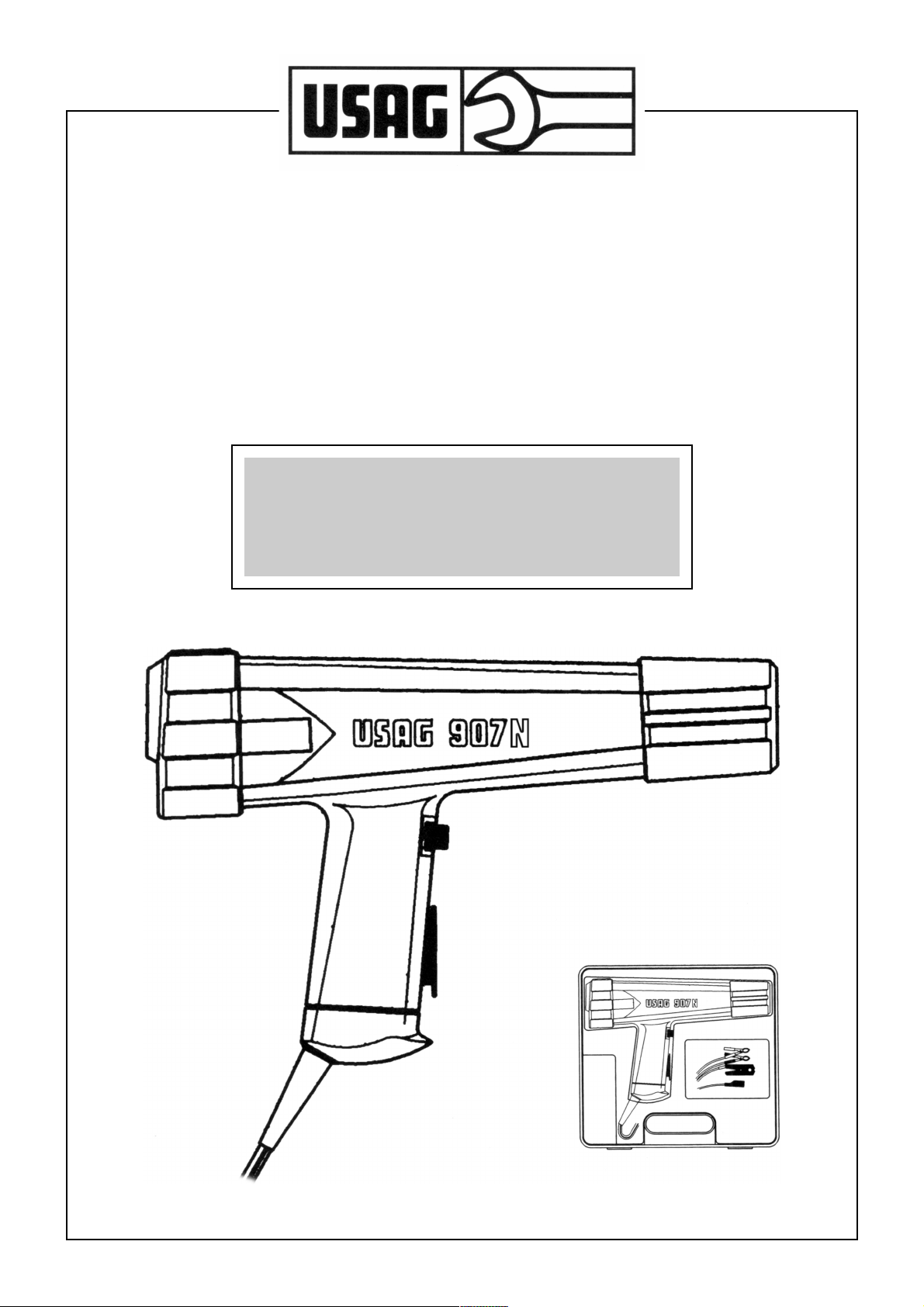
PISTOLA STROBOSCOPICA
TIMING LIGHT
LAMPE STROBOSCOPIQUE
ISTRUZIONI D’USO
OPERATING INSTRUCTIONS
INSTRUCTION DE SERVICE
907 N
Page 2

Pistola Stroboscopica 907N
1. PREMESSA
La pistola stroboscopica 907N può essere utilizzata su motori a benzina a 4
o 2 tempi fino a 2 scintille per giro. Le
misure stroboscopiche di giri e di anticipo sono indipendenti dal numero dei
cilindri e si possono effettuare collegando la pinza induttiva al cavo candela
del primo cilindro.
Le tensioni continue o di picco possono essere effettuate collegando il MORSETTO ROSSO 1 al punto di prova.
Le letture dello Dwell possono essere
effettuate su camme dei distributori di
accensione in gradi o percentuale per
ogni cilindro.
Misure in millisecondi del tempo di iniezione su iniettori o del ciclo di lavoro
utile su altri attuatori, si effettuano collegando il MORSETTO ROSSO 1 e la
pinza a induzione al cavo candela del
cilindro relativo.
Possono essere effettuate misure di giri
tramite stroboscopio, senza contatto e
senza applicare catarifrangenti sulla
parte rotante.
2. CONTROLLI
Senza smontare le parti in esame è
possibile diagnosticare difetti ed usure:
1 - nel sistema di apertura contatti;
2 - nei meccanismi di espansione cen-
trifuga dell’anticipo;
3 - nel sistema di distribuzione;
4 - nel sistema di anticipo a depressione;
5 - nel sistema di ritardo a depressione;
6 - nella batteria e sistema di carica.
Un controllo ed una corretta regolazione dei vari organi sopra descritti consentono di ottimizzare il rendimento, di
limitare le usure, i consumi di carburante e l'emissione di gas di scarico nocivi.
CARATTERISTICHE TECNICHE
3. PRECAUZIONI
Allo scopo di garantire un funzionamento prolungato nel tempo, è necessario
avvolgere i cavi morbidamente, mai
intorno alla pistola.
4. ISTRUZIONI PER L’USO
• Collegare la pistola come illustrato
nello schema di Fig. 1.
Un collegamento invertito dei morsetti ROSSO/NERO alla batteria non
causa guasti alla pistola. Sistemare
la pinza a circa 10 cm dal distributo-
re con freccia rivolta verso la candela. Sistemare i cavi della pistola lontano da tubi di scappamento, parti
rotanti e da cavi ad alta tensione.
• Verificare che i collegamenti elettrici della bobina siano corretti. Collegamenti invertiti possono provocare instabilità di letture e diminuzione del rendimento del motore.
• Verificare che le tacche siano ben
visibili; si possono tracciare altrimenti due segni in coincidenza tra
loro sul carter e sulla puleggia dell'albero motore, con il pistone del 1°
cilindro al Punto Morto Superiore in
fase di compressione.
• Premendo il tasto D la pistola deve
lampeggiare regolarmente; instabilità nel lampeggio potrebbero essere causate da:
- cavi candela non resistivi;
- scariche tra poli della calotta o verso
massa dovuti a sporcizia o umidità;
- dispersioni verso massa o fra i cavi
dovuta ad invecchiamento o crepe
nell'isolante;
- usura ed eccessiva distanza fra
spazzola rotante e poli o contatto
centrale della calotta;
LETTURE SCALA RISOLUZIONE
– Giri 400÷19.999 giri/min. 1 giro/min.
– Anticipo stroboscopico 0÷78°/90° (400/465 giri/min.) 0.1°
– Dwell (ciclo utile) per 0÷ 65 ms 0.1 ms
ogni cilindro 0÷100% 0.1%
0÷120° (> 600 giri/min.) 0.1°
– Tensione continua 1÷70 Volt 0.1 Volt
– Tensione di picco 1÷70 Volt 0.1 Volt
– Contagiri stroboscopico 60÷6000 giri/min. 1 giro/min.
– Memoria letture 6 s (dal rilascio del tasto D)
– Alimentazione 9.5÷15 Volt (9.5÷35 V opzionale)
- elettrodi della candela troppo vicini
o con eccessivi residui carboniosi;
- tensione sulla candela troppo bassa per difetti dell'impianto di accensione;
- pistola troppo vicina ai cavi delle candele, allo spinterogeno o alla bobina.
• Controllare in controluce che le
superfici rettificate dei nuclei della pinza si richiudano andando a
combaciare tra loro. Togliere con
uno strofinaccio eventuali corpi
estranei, grasso e polvere che
possono incunearsi tra le superfici stesse.
5. CONTROLLO ANGOLO DI CAMMA
• Avviare il motore e riscaldarlo fino
ad ottenere una rotazione regolare
al minimo.
• Staccare il tubo del depressore se
indicato nel manuale dati.
• Negli impianti a ruttore o con accensione transistorizzata il controllo dell’angolo di camma DWELL si
effettua collegando il morsetto
ROSSO 1 al negativo bobina.
• Negli impianti con sensore a riluttanza una lettura nulla indica un sensore o il cablaggio interrotto. Una
lettura molto diversa da 3÷5 ms è
causata da una distanza poli/sensore diversa dalle prescrizioni, un modulo difettoso o una resistenza di
collegamento a massa superiore a
0.1 Ohm. Controllare la centralina,
nel caso quest’ultima fornisse il segnale di comando.
• Nel caso di impianti a ruttore seguire
le istruzioni del foglio giallo per controllare la corrispondenza della misura in gradi o percentuale con i dati
del costruttore. Letture fuori tolleranza possono essere dovute a: distanza dei contatti errata, piastra porta
contatti danneggiata, albero del distributore, contatti o camme usurati.
• Portare il motore a 2000 giri, la variazione non dovrebbe superare i 3
gradi (alcuni tipi hanno variazioni superiori, è quindi necessario controllare le caratteristiche dichiarate dal
costruttore prima di sostituirlo).
Variazioni superiori possono essere causate da: usure degli elementi
descritti al paragrafo precedente,
pernino dei contatti usurato o contatti allentati.
Page 3

Se si avesse un’eccessiva variazione collegando il tubo del depressore,
potrebbe essere consumato il perno
della piastra porta contatti. Assenza
di variazioni o variazioni errate possono essere causate da fessurazioni
della membrana della capsula.
Nota: Negli impianti a ruttore, un ec-
cessivo logoramento negli organi del
distributore provoca variazioni anomale di anticipo e una diminuzione
del rendimento del motore. Un angolo di chiusura troppo basso provoca un'insufficiente accensione; un
angolo troppo elevato provoca una
prematura bruciatura dei contatti.
Ricordare di effettuare il controllo di anticipo dopo l’eventuale riparazione.
6. CONTROLLO DEL NUMERO DI GIRI
• Letture fino a 19 990 giri/min. si effettuano tramite pinza induttiva.
Misure stroboscopiche fino a 6 000
giri/min., si effettuano seguendo le
istruzioni del foglio giallo.
• Negli impianti a carburatore e in alcuni ad iniezione elettronica, regolare il minimo agendo sull'apposita
vite per un corretto rapporto aria/
benzina fino ad ottenere una rotazione regolare del motore.
Nota: La perfetta regolazione del mini-
mo limita i consumi di carburante,
l’emissione dei gas di scarico nocivi, evita inoltre fastidiosi arresti del
motore.
7. CONTROLLO CONDOTTI DI SFIATO
• Il controllo si effettua staccando i tubi
che vanno dal carter alla testa del
motore o al carburatore. Chiudendo con un dito l’estremità del tubo si
dovrà osservare un calo di 50 o più
giri; diversamente bisogna controllare che non vi siano occlusioni di
filtri o eventuali guasti di valvole facenti parte del condotto.
8. CONTROLLO DELLA POSIZIONE
DELLE TACCHE DI ANTICIPO
• Volendo limitare il controllo alla posizione delle tacche, portare il display a 00,1 tramite il tasto C–.
• Portare il motore al minimo e, salvo
diversa indicazione del costruttore,
staccare il tubetto del depressore.
Premendo il tasto D la pistola deve
lampeggiare. Se la tacca dell’anticipo fisso sul motore fosse fuori
posto ruotare il distributore.
Lo stesso procedimento può essere
usato per il controllo delle tacche di
anticipo centrifugo. Negli impianti con
centralina elettronica controllare il
sensore di temperatura motore.
9. MISURA DI ANTICIPO
• Controllare che il numero dei giri sia
quello indicato dai dati.
• Tramite i tasti C
sul numero di gradi indicato dai dati
del costruttore; illuminare le tacche
del PMS sulla puleggia e sul carter,
facendo attenzione a non confonderle con altre. Le tacche devono
coincidere entro le tolleranze ammesse dal costruttore, diversamente bisogna orientare il distributore e
controllare che la cinghia di distribuzione non abbia saltato un dente.
Negli impianti con centralina elettronica controllare che il sensore di
temperatura motore non sia difettoso.
• Se la tacca oscilla troppo controllare la catena e gli altri organi di distribuzione.
Nota: In alcuni autoveicoli le tacche di
riferimento possono essere illuminate meglio tenendo la pistola in posizione scomoda per la lettura. Per
memorizzare la lettura rilasciare il
tasto D nel momento di coincidenza delle tacche, quindi leggere il valore entro 6 secondi.
10. MISURA DI ANTICIPO CENTRIFUGO
• Portare il motore al regime di giri
indicato dai dati.
• Tramite i tasti C
sul numero di gradi indicato dai dati;
le tacche del PMS sul carter e sulla
puleggia dell'albero motore dovranno coincidere. Se l’errore fosse eccessivo controllare il sensore di temperatura motore, se la tacca oscillasse troppo o si spostasse in modo
irregolare durante le accelerazioni,
controllare che la cinghia di distribuzione non sia lenta.
Negli impianti a ruttore potrebbero
essere usurate o impastate le masse centrifughe e le molle, usurato il
perno della piastra portacontatti o
± portare il display
± portare il display
l’albero del distributore.
Nota: Un anticipo centrifugo difettoso,
provoca mancanza di ripresa e “buchi” di potenza a determinati regimi
di giri.
11. CONTROLLO ANTICIPO A DEPRESSIONE
• Inserendo il tubetto di depressione
si dovrà notare un aumento dell’anticipo, la cui entità può essere misurata riportando in coincidenza le
tacche del PMS.
Se negli impianti a ruttore la variazione fosse inesistente o troppo fuori dalle tolleranze, devono essere
controllati la membrana e la piastra
porta contatti.
Nota: Negli impianti di accensione/inie-
zione comandati da centralina elettronica la non corrispondenza dell’anticipo a depressione alle specifiche del costruttore può essere dovuta al non corretto funzionamento
del sensore di depressione.
12. CONTROLLO DI RITARDO IN ACCELE-
RAZIONE
Il controllo può essere effettuato nei
motori provvisti di tale dispositivo.
• Portare il display a 00,1 tramite il tasto C
±. Inserendo il tubetto del ritar-
do a depressione si dovrà notare una
temporanea diminuzione dell’anticipo durante le accelerazioni. Nel caso
di variazioni anomale controllare gli
organi meccanici addetti o il sensore
di depressione nelle centraline.
13. MISURE DI TENSIONE
Le misure di tensione continua di batteria all’avviamento, di carica dell’alternatore, variazioni di tensione su sensori di temperatura, potenziometro a
farfalla, di picco di sensori induttivi di
PMS e giri o di comando centraline o
moduli di accensione possono essere
effettuate collegando il morsetto ROSSO 1 al contatto di segnale.
14. RESET
Se il display della pistola presentasse
delle anomalie durante il collegamento
dei morsetti ROSSO/NERO di alimentazione o durante il funzionamento, allontanare la pistola da eventuali fonti
di disturbo (cavi candela, distributori, alternatori) e premere il tasto RESET.
Page 4

Timing Light 907N
1. GENERAL INFORMATION
The timing light 907N can be used on
2 or 4 stroke petrol engines with up to
2 sparks per revolution. Stroboscopic
RPM and advance measurements are
independent from the number of cylinders and can be carried out by connecting the inductive clamp to the spark
cable of the No.1 cylinder.
DC or peak voltages can be measured
by connecting the RED 1 clip to the test
point. Dwell of each distributors’ camshafts can be measured both in degrees or in percentage.
Injection time or duty cycle measurements in milliseconds of injectors or
other actuators can be made by connecting the RED 1 CLIP and the inductive clamp to the spark cable of the relevant cylinder.
RPM measurements can be carried out
by the stroboscope, without contact
and without sticking any reflecting
tapes to the rotating part.
2. CHECKS
It is possible to diagnose faults and
wears without disassembling the part
concerned:
1 - in the contact breaker system;
2 - in the centrifugal advance mecha-
nism;
3 - in the timing system;
4 - in the vacuum advance system;
5 - in the vacuum retard system;
6 - in the battery and charging system.
A check and a correct adjusting of the
different parts described above allow
to optimize the engine performance,
reduce wears, fuel consumption and
harmful gas emissions.
TECHNICAL FEATURES
3. PRECAUTIONS
In order to prolong the lifetime of the
unit, it is necessary to softly coil the
cables but never wrap them around the
timing light.
4. OPERATING INSTRUCTIONS
• Connect the timing light as shown
in Fig. 1.
A reversed connection to battery of
the RED/BLACK clips does not
cause damages to the timing light.
Mount the clamp at about 10 cm
from the distributor, with the arrow
pointing towards the spark plug.
Make sure the cables are far from
exhaust pipes, rotating parts and
high voltage leads.
• Check that the coil’s electrical connections are correct. Reversed connections can cause reading unsteadiness and decrease the engine
performance.
• Check that the timing marks can be
seen clearly; bring otherwise the
piston of the No.1 cylinder at TDC
in compression stroke, and trace
with a white chalk two signs in line
on the crankcase and the crankshaft
pulley.
• By pressing the D key, the strobe
light should flash regularly; an irregular flashing could be caused by:
- non-resistive spark cables;
- discharges between cap poles or to
ground due to dirt or moisture;
- leakage to ground or between cables due to ageing or cracks in the
insulating sheath;
- wear or excessive gap between ro-
READING SCALE RESOLUTION
– RPM 400÷19.999 rpm 1 rpm
– Stroboscopic advance 0÷78°/90° (400/465 rpm) 0.1°
– DWELL (for each cylinder) 0÷ 65 ms 0.1 ms
0÷100% 0.1%
0÷120° (> 600 rpm) 0.1°
– DC Voltage 1÷70 Volts 0.1 Volt
– Peak Voltage 1÷70 Volts 0.1 Volt
– Stroboscopic RPM counter 60÷6000 rpm 1 rpm
– Memory of readings 6 s (from key D release)
– Power supply 9.5÷15 Volts (9.5÷35 V optional)
tor arm and poles or cap’s central
contact;
- too small spark gap or spark electrodes with too much carbon residues;
- too low voltage on the spark plug
due to faults in the ignition system;
- timing light too near to spark cables,
distributor or ignition coil.
• Check against the light that the
clamp’s cores match completely.
With a cloth, remove possible
grease and dust.
5. CHECKING THE DWELL ANGLE
• Start the engine and make it warm
till reaching a regular rotation at idle.
• Disconnect the vacuum tube, if
specified in the data manual.
• In breaker points or transistorized ignition systems, the Dwell angle is
checked by connecting the RED 1
clip to coil negative.
• In some transistorized systems, a
zero reading means an interrupted
reluctor or wiring. If the reading is
very different from 3÷5 ms, the causes can be: a wrong distance between poles and reluctor, a faulty
module or a resistance of the ground
connection higher than 0.1 Ohm.
Check the ECU, in case it should
directly drive the ignition coil.
• In case of breaker points systems
follow the instructions in the yellow
sheet to check that the measurement in degrees or percentage corresponds to the manufacturer’s
data. Readings out of tolerance can
be due to: wrong distance between
contacts, damages to the base plate
or the contacts, worn camshaft and
distributor shaft .
• Bring the engine to 2000 RPM, variation should not be more than 3 degrees (some distributors have higher
variations, it is therefore necessary to
check the features declared by the
manufacturer before changing it).
Higher variations can be due to the
same causes described in the previous chapter, loose contacts, used
contacts’ pivot.
In case of an excessive variation
when connecting the vacuum tube,
the pivot post of the base plate could
be damaged.
Page 5

No variations or wrong variations
could be caused by: diaphragm of
the vacuum advance variator
cracked.
Note: In breaker points systems, an
excessive wear of the distributor’s
parts causes abnormal advance
variations and a decreased engine
performance. A too low Dwell angle
causes an insufficient ignition; a too
high Dwell angle causes a premature burning of contacts.
Remember to check the advance
after repair.
6. CHECKING THE RPM NUMBER
• Reading up to 19 990 RPM can be
made through the inductive clamp.
Direct measurements up to 6 000
RPM are possible with the stroboscope. In this case refer to the yellow instruction sheet.
• In carburettor systems and in some
early electronic injection systems,
adjust the advance through the special screw for a correct air/petrol
mixture until obtaining a regular engine rotation.
Note: A perfect idle adjustment limits
fuel consumption, emission of harmful exhaust gases and avoids engine
stops.
7. CHECKING BREATHER PIPES
• The check is made by disconnecting the tubes that go from the crankcase to the engine head or to the
carburettor. By closing the top of the
tube with a finger, a drop of 50 or
more RPM should occur. If not,
check that there are no filter occlusions or possible damages of the
pipe’s valves.
8. CHECKING THE MECHANICAL
POSITION OF TIMING MARKS
• To check only the timing marks’ position, bring the display to 00,1
through the C– key.
• Bring the engine to idle and disconnect the vacuum tube or observe the
instructions of the manufacturer.
By pressing the D key, the timing
light should flash.
If the timing mark is too far from the
correct position, rotate the distribu-
tor or check that the distribution belt
has not jumped a cog.
The same procedure may be used
for checking the marks of centrifugal advance.
In systems with ECU, check the engine temperature sensor.
9. ADVANCE MEASUREMENT
• Check that the RPM number is the
same shown in the manufacturer’s
data.
• Press the C
shows the number of degrees indicated in the manufacturer’s data.
Lighten the TDC marks on the pulley and crankcase taking care not
to confuse them with the other
ones.
Check that the error in the alignment
of TDC marks is within the tolerances foreseen by the manufacturer,
otherwise turn the distributor.
In ECU systems, check that the timing belt has not jumped a cog or
that the engine temperature sensor
is not faulty.
• If the TDC mark swings too much
check the distribution belt and the distributor mechanisms in point systems.
Note: In some vehicles, reference
marks can be better lightened by
keeping the timing light in an uncomfortable position for the reading.
In this case store the reading when
the marks are aligned by releasing
the key D, then read the value with-
in 6 seconds.
10. CENTRIFUGAL ADVANCE
MEASUREMENT
• Run the engine to the speed indicated in the data manual.
• Press the C
shows the number of degrees indicated in the data manual or in manufacturer’s data; TDC marks on the
crankcase and on the crankshaft
pulley should be in line.
If the error is excessive, check the
engine temperature sensor in ECU
systems; if the mark swings too
much, or moves irregularly during
accelerations, check that the timing
belt is not loose.
In points systems check the contact
spring; the centrifugal mechanism
± key until the display
± key until the display
could otherwise be worn as well as
the pivots or the distributor shaft.
Note: A faulty centrifugal timing can
result in lack of pick-up and flat
points in engine power at certain
engine speeds.
11. CHECKING THE VACUUM ADVANCE
• By connecting the vacuum tube,
advance should increase. It can be
measured by bringing TDC marks
in line.
In points systems: if there is no variation or if the advance is too much
out of tolerances, the diaphragm
and the baseplate should be
checked.
Note: In ECU controlled ignition/injec-
tion systems, if the advance caused
by the vacuum device does not correspond to the manufacturer’s specifications, it can be due to a wrong
operation of the vacuum sensor.
12. CHECKING THE ACCELERATION
RETARD
This check can be made in engines
provided with this device.
• Press the C
play to 00,1. By connecting the vacuum retard tube during sudden accelerations, the advance should
momentarily decrease.
In case of anomalous variations,
check the diaphragm or other mechanical parts.
13. VOLTAGE MEASUREMENTS
Measurements of direct battery voltage at cranking, alternator’s charge,
voltage variations on temperature sensors, throttle potentiometer, peak voltage of TDC inductive sensors, RPM
sensors or the control signal sent by
the ECU to the ignition modules can be
made by connecting the RED 1 clip to
the signal contact.
14. RESET
If the timing light display should show
faults while connecting the RED/
BLACK power clips or during operation,
take the timing light away from possible noise sources (spark cables, distributors, alternators) and press RESET.
± key to bring the dis-
Page 6

Lampe Stroboscopique 907N
1. INTRODUCTION
La lampe stroboscopique 907N peut
être utilisée sur moteurs à essence à 4
ou 2 temps jusqu’à 2 étincelles par tour.
Les mesures stroboscopiques des tours
et de d’avance sont indépendantes du
nombre des cylindres et peuvent être
effectuées en connectant la pince à induction au câble bougie du 1er cylindre.
Les tensions continues ou de crête
peuvent être mesurées en connectant
la borne ROUGE 1 au point d’essai.
Les lectures du Dwell des cames des
distributeurs d’allumage peuvent être
effectuées en degrés ou pourcentage.
Les mesures en millisecondes du
temps d’injection sur les injecteurs ou
du cycle de travail utile (duty cycle) sur
d’autres actuateurs s’effectuent en connectant la BORNE ROUGE 1 et la pince à induction au câble bougie du cylindre correspondant.
On peut aussi mesurer les tours avec
le stroboscope, sans contact et sans
appliquer aucun catadioptre sur la partie tournante.
2. CONTRÔLES
Sans démonter les parties en examen,
il est possible de diagnostiquer les défauts et les usures:
1 - dans le système d’ouverture des
contacts;
2 - dans les mécanismes d’expansion
centrifugeuse de l’avance;
3 - dans le système de distribution;
4 - dans le système d’avance à dépression;
5 - dans le système de retard à dépression;
6 - dans les capteurs, la batterie et le
système de charge.
Un contrôle et un réglage correct des
différentes parties décrites ci-dessus
permettent d’optimiser le rendement,
CARACTÉRISTIQUES TECHNIQUES
de limiter les usures, la consommation
de carburant et l’émission des gaz
d’échappement nuisibles.
3. PRÉCAUTIONS
Pour garantir un fonctionnement prolongé dans le temps, il est nécessaire
d’enrouler les câbles moelleusement,
jamais autour de la lampe.
4. INSTRUCTIONS POUR L’EMPLOI
• Monter la lampe comme illustré
dans le schéma de Fig. 1.
Un branchement inversé des bornes ROUGE/NOIRE à la batterie,
n’endommage pas la lampe. Brancher la pince à environ 10 cm du
distributeur avec la flèche tournée
vers la bougie. Placer les câbles de
la lampe loin des tuyaux d’échappement, parties tournantes et des
câbles haute tension.
• Vérifier que les connexions électriques de la bobine soient correctes.
Des connexions inversées peuvent
causer des lectures instables et la
diminution du rendement du moteur.
• Vérifier que les repères soient bien
visibles; sinon on peut tracer deux
signes en ligne sur le carter et sur la
poulie de l’arbre moteur, avec le piston du cylindre No. 1 au Point Mort
Haut en phase de compression.
• En pressant la touche D, la lampe
doit clignoter régulièrement; des instabilités du clignotement pourraient
être causées par:
- câbles bougie non résistifs;
- décharges entre les pôles de la tête
d’allumeur ou vers la masse dues à
LECTURES ÉCHELLE RESOLUTION
– Tours 400÷19.999 tours/min. 1 tour/min.
– Avance stroboscopique 0÷78°/90° (400/465 tours/min.) 0.1°
– Dwell (cycle utile) 0÷ 65 ms 0.1 ms
pour chaque cylindre 0÷100% 0.1%
0÷120° (> 600 tours/min.) 0.1°
– Tension continue 1÷ 70 Volts 0.1 Volt
– Tension de crête 1÷70 Volts 0.1 Volt
– Compte-tour stroboscopique 60÷6000 tours/min. 1 tour/min.
– Mémoire des lectures 6 s (après le relâchement de la touche D)
– Alimentation 9.5÷15 Volts (9.5÷35 V optionnel)
saleté ou humidité;
- dispersions vers la masse ou entre
les câbles à cause du vieillissage ou
fissures dans l’isolant;
- usure et distance excessive entre le
doigt de l’allumeur et les pôles ou le
contact central de la tête d’allumeur;
- électrodes de la bougie trop proches
ou avec trop de résidus de carbone;
- tension trop basse sur la bougie à
cause de défauts du système d’allumage;
- lampe stroboscopique trop proche
des câbles des bougies, de l’allumeur ou de la bobine.
• Contrôler à contre jour que les
noyaux de la pince joignent parfaitement. Avec un chiffon, enlever les éventuels corps étrangers,
graisse et poussière qui peuvent
s’enfoncer entre les surfaces.
5. CONTRÔLE DE L’ANGLE DE CAME
• Démarrer le moteur et le réchauffer
jusqu’à obtenir une rotation régulière au ralenti.
• Détacher le tube du dépresseur, si
indiqué dans le manuel des données.
• Dans les systèmes avec allumage
à rupteur ou transistorisé, le contrôle de l’angle de came DWELL s’effectue en connectant la borne ROUGE 1 au négatif bobine.
• Dans les systèmes avec capteur à
réluctance, une lecture à zéro indique un capteur ou le câblage interrompu. Une lecture très différente de
3÷5 ms est causée par une distance
pôles/capteur différente des prescriptions, par un module défectueux ou
une résistance de connexion à la
masse supérieure à 0.1Ω. Contrôler
la boîte électronique, dans le cas où
elle commande le module d’allumage.
• En cas de systèmes à rupteur suivre les instructions du papier jaune.
Si la mesure en degrés ou pourcentage ne correspond pas aux données du constructeur, la distance
des contacts pourrait être incorrecte, les contacts, les cames ou l’axe
du distributeur usés.
• Porter le moteur à 2000 tours, la variation ne devrait pas supérer 3 degrés (en cas de doutes se rapporter
aux caractéristiques déclarées par
le constructeur avant de le remplacer).
Page 7

Des intabilités supérieures peuvent
être causées par: arbre ou bague du
distributeur endommagés, pivot des
contacts consommés, contacts relâchés.
Des variations incorrectes peuvent
être causées par: pivot de la plaque
porte-contacts consommé ou membrane de la capsule fissurée.
Note: Un angle de fermeture des con-
tacts élevé donne lieu à une brûlure
prématurée des contacts, un angle
de fermeture trop bas donne lieu à
un allumage insuffisant et par conséquence une diminution du rendement du moteur.
Contrôler l’avance après la réparation.
6. CONTRÔLE DU NOMBRE DES TOURS
• Les lectures jusqu’à 19 990 tours/
min. s’effectuent avec la pince à induction.
Mesures stroboscopiques jusqu’à
6 000 tours/min. s’effectuent en suivant les instructions du papier jaune.
• Dans les systèmes à carburateur et
dans quelques uns à injection électronique, régler le ralenti par l’intermédiaire de la vis spéciale pour un
rapport correct air/essence.
7. CONTRÔLE DU RENIFLARD DE L’HUILE
• Le contrôle s’effectue en détachant
les tubes qui vont du carter à la tête
du moteur.
En fermant l’extrémité du tube avec
un doigt, on devra observer une diminution de 50 tours ou plus; sinon
on doit contrôler qu’il n’y ait pas
d’obstructions des filtres ou de pannes éventuelles des soupapes du
conduit.
8. CONTRÔLE DE LA POSITION DES
REPÈRES D’AVANCE
• Si l’on veut limiter le contrôle à la
position des repères, porter l’afficheur à 00,1 par l’intermédiaire de
la touche C–.
• Porter le moteur au ralenti et, sauf
indication différente du constructeur,
détacher le tube du dépresseur.
En pressant la touche D, la lampe
doit clignoter. Si le repère de la poulie n’est pas dans la position correcte, tourner le distributeur.
La même procédure peut être adoptée pour le contrôle des repères de
l’avance centrifuge.
Dans les systèmes avec boîte électronique, contrôler le capteur de
température du moteur.
9. MESURE D’AVANCE
• Contrôler que le nombre des tours
soit celui indiqué par les données.
• Avec la touche C
au numéro de degrés indiqué par
les données techniques; illuminer
les repères de PMH en faisant
éventuellement attention à ne pas
les confondre avec d’autres.
Les repères doivent coïncider dans
les tolérances admises par le constructeur, sinon il faut orienter le distributeur ou contrôler que la chaîne
ou la courroie de distribution n’ait
pas sauté un dent.
Dans les systèmes avec boîte électronique contrôler le capteur de température moteur.
Note: Dans quelques véhicules, les re-
pères de référence peuvent être
mieux illuminés en tenant la lampe
stroboscopique en position inconfortable pour la lecture. En ce cas relâcher la touche D quand les repères sont en ligne, donc lire la valeur
dans 6 secondes.
10. MESURE D’AVANCE CENTRIFUGE
• Porter le moteur au régime de tours
indiqué sur les données.
• Avec la touche C
sur le numéro de degrés indiqué sur
les données; les repères de PMH
sur le carter et sur la poulie de l’arbre moteur devront coïncider.
Si l’erreur est excessif, contrôler le
capteur de température du moteur.
Si le repère oscille trop, bouge irrégulièrement pendant les accélérations, contrôler que la courroie de
distribution ne soit pas lente ou
usée.
Dans les systèmes à rupteur contrôler le mécanisme centrifuge, les
ressorts, les pivots ou l’axe du distributeur.
Note: Une avance centrifuge défec-
tueuse donne lieu à un manque de
reprise et à des “trous” de puissance à certains régimes de tours.
± porter l’afficheur
± porter l’afficheur
11. CONTRÔLE DE L’AVANCE À DÉPRESSION
• Quand on introduit le tube de dé-
pression, on devra remarquer une
augmentation de l’avance, qui peut
être mesurée en reportant les repères de PMH en ligne.
Si dans les systèmes à rupteur, il
n’y a pas de variation ou si elle est
trop hors des limites, on doit contrôler la membrane et la plaque porte-contacts.
Note: Dans les systèmes d’allumage/
injection commandés par boîte électronique, si l’avance à dépression
ne correspond pas aux spécifications du constructeur, contrôler le
capteur de dépression.
12. CONTRÔLE DU RETARD EN ACCÉLÉRATION
Le contrôle peut être fait sur les moteurs pourvus de ce dispositif.
• Porter l’afficheur à 00,1 avec la tou-
±. Quand on introduit le tube
che C
du retard à dépression pendant les
accélérations, on devra remarquer
une diminution temporaire de
l’avance.
En cas de variations anomales, contrôler les organes mécaniques concernés ou le capteur de dépression
dans les boîtes électroniques.
13. MESURES DE TENSION
En connectant la borne ROUGE 1 au
point de mesure on peut contrôler la
baisse de tension de batterie au démarrage et la charge de l’alternateur, variations de tension sur les capteurs de
température, potentiomètre d’accélérateur, tensions de crête des capteurs inductifs de PMH et tours, signaux des
boîtes électroniques envoyés au module d’allumage.
14. RESET
Si l’afficheur de la lampe présente des
anomalies pendant le branchement des
bornes ROUGE/NOIRE d’alimentation
ou pendant le fonctionnement, éloigner
la lampe des éventuels brouillages (câbles bougie, distributeurs, alternateurs)
et appuyer sur la touche RESET.
Page 8
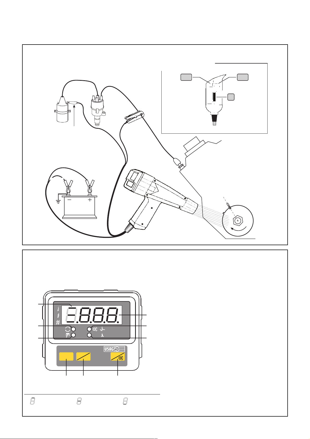
COLLEGAMENTO PER MISURE DI GIRI, ANTICIPO E DWELL
SWK Utensilerie S.r.l. Via Volta 3; 21020 Monvalle (VA) – Italy
Tel +39/0332/790111 Fax +39/0332/790602 Internet: www.usag.it E-mail: [email protected]
CONNECTION FOR RPM, ADVANCE AND DWELL MEASUREMENTS
CONNEXION POUR MESURES DE TOURS, AVANCE ET DWELL.
C + C –
Tasto incremento anticipo
Key for advance increase
Touche pour augmenter
+ –
Morsetto Rosso 1
Red Clip 1
Borne Rouge 1
Nero 4
Black 4
Noir 4
12 V
Rosso 5
Red 5
Rouge 5
Cil. 1
Cyl. 1
Cyl. 1
l'avance
Tasto azzeramento anticipo
Key for zeroing advance
Touche de mise à zéro de
D
Lettura/Memoria
Reading/Memory
Lecture/Mémoire
PMS
TDC
PMH
Puleggia o Volano
Pulley or Flywheel
Poulie ou Volant Moteur
l'avance
DISPLAY PISTOLA
TIMING LIGHT DISPLAY
AFFICHEUR LAMPE STROBOSCOPIQUE
➀
➁
min.
V=
➂
RESET
2
4
V
Pistola stroboscopica
Timing Light
Lampe stroboscopique
➃
➄
➅
1. Segmenti* Selez. scintille/giro
Segments* Spark/RPM selection
Segments* Sélect. étincelles/tour
2. LED 1 Giri/min. - RPM - Tours/min.
3. LED 2 Anticipo - Advance - Avance
4. Display Giri/min., Anticipo, Dwell, Volt
Display RPM, Advance, Dwell, Volts
Afficheur Tours/min., Avance, Dwell, Volts
5. LED 3 Dwell - Dwell - Dwell
6. LED 4 Tensione continua e di picco
Direct and peak voltage
Tension continue et de crête
7. Azzeramento - Reset - Mise à zéro
Fig. 1
Mod. 907 N – USAG 10.10.2001
➆➇ ➈
1 scintilla ogni 2 giri
*)
1 spark every 2 revs
1 étincelle chaque 2 tours
1 scintilla per giro (DIS)
1 spark per rev (DIS)
1 étincelle par tour (DIS)
2 scintille per giro
2 sparks per rev
2 étincelles par tour
8. 2/4 Tempi - 2/4 Strokes - 2/4 Temps
9. Volt/Dwell Vcc e picco - V DC & Peak - Vcc et crête
Ciclo utile - Duty cycle - Cycle utile
Fig. 2
 Loading...