

Ursalink UR75 Edge Quick Start Manual
1
UR75 Edge
Ursalink Technology Co., Ltd.
Quick Start Guide
1
Welcome
Document
Description
Ursalink UR75 Edge Datasheet
Datasheet for the Ursalink UR75 Edge gateway.
Ursalink UR75 Edge User Guide
Users could refer to the guide for instruction on how to log in the
web GUI, and how to configure all the settings.
Thank you for choosing Ursalink UR75 Edge gateway.
This guide describes how to install the UR75 Edge gateway and how to log in the Web GUI to configure the
device. Once you complete the installation, refer to the Ursalink UR75 Edge User Guide for instructions on
how to perform configurations on the device.
Related Documents
This Start Guide only explains the installation of Ursalink UR75 Edge gateway. For more functionality and
advanced settings, please refer to the relevant documents as below.
The related documents are available on Ursalink website: http://www.ursalink.com.
Declaration of Conformity
UR75 Edge are in conformity with the essential requirements and other relevant provisions of the CE, FCC,
and RoHS.
For assistance, please contact
Ursalink technical support:
Email: support@ursalink.com
Tel: 86-592-5023060
Fax: 86-592-5023065
www.ursalink.com
Ursalink UR75 Quick Start Guide
2
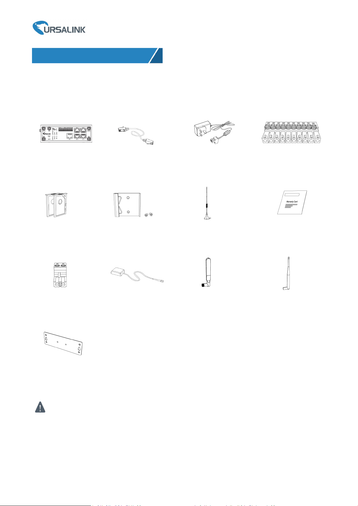
1 × UR75 Edge gateway
1 × Ethernet Cable
1 × Power Adapter
1 × 10-Pin Pluggable
Terminal
2 × SIM Card Slots
1 × DIN Rail Kit
2 × Magnetic Mount
Cellular Antennas
1 × Warranty Card
1 × 2-Pin Pluggable
Terminal (Optional)
1 × GPS Antenna
(Optional)
2 × Stubby Wi-Fi
Antennas (Optional)
2 × Stubby Cellular
Antennas (Optional)
1 × Wall Mounting Bracket
(Optional)
If any of the above items is missing or damaged, please contact your Ursalink sales
representative.
1. Packing List
Before you begin to install the UR75 Edge gateway, please check the package contents to verify that you
have received the items below.
1.1 Package Contents
www.ursalink.com
3
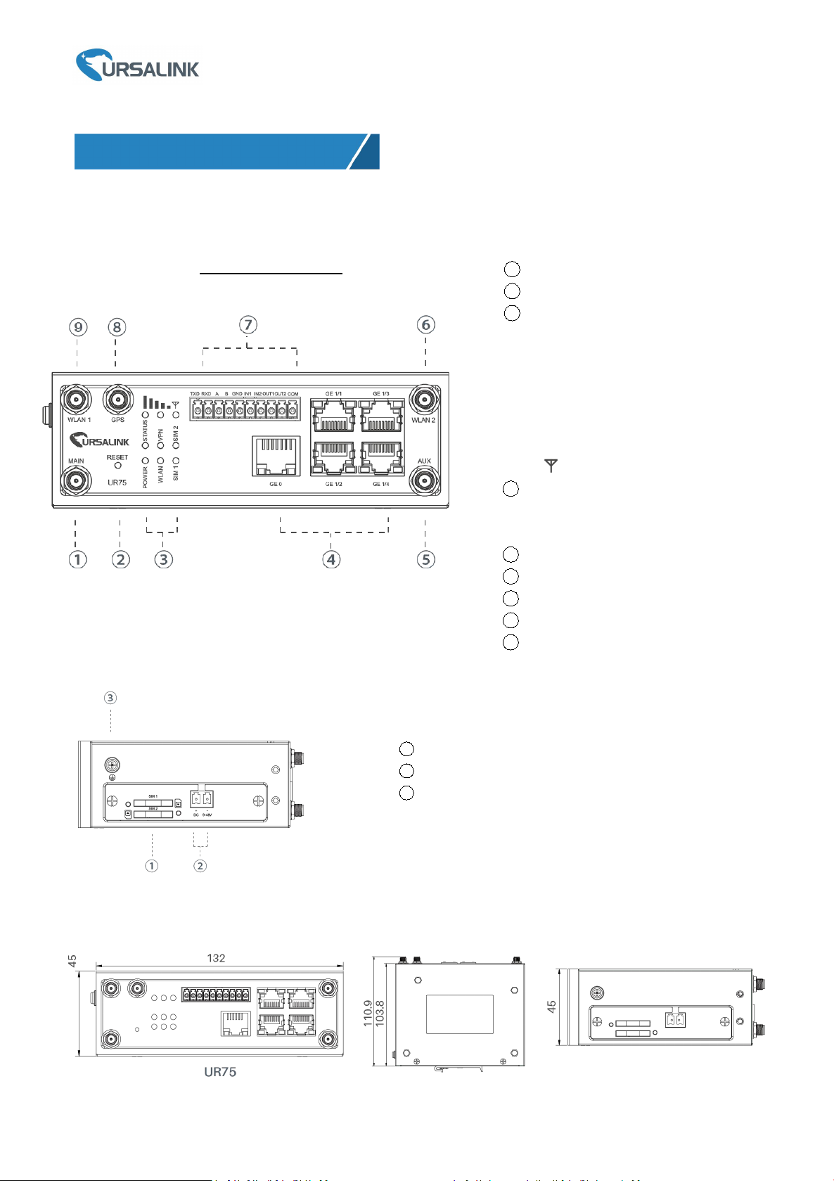
2.1 Overview
2. Hardware Introduction
1
Main Cellular Antenna Connector
2
Reset Button
3
LED Indicator Area
POWER: Power Indicator
STATUS: Status Indicator
WLAN: Wi-Fi Indicator
VPN: VPN Indicator
SIM 1: SIM 1 Status Indicator
SIM 2: SIM 2 Status Indicator
: Signal Strength Indicator
4
Ethernet Port Indicator
Orange for data transmission;
Green for network rate
5
AUX Cellular Antenna
6
WLAN 2: Wi-Fi Antenna Connector 2
7
Serial Port & I/O
8
GPS: GPS Antenna Connector
9
WLAN 1: Wi-Fi Antenna Connector 1
A. Front Panel
Ursalink UR75 Quick Start Guide
UR75 Edge Front Panel
B. Left Side Panel
2.2 Dimensions (mm)
www.ursalink.com
1
SIM Card Slot
2
Power Connector
3
Grounding Stud
4
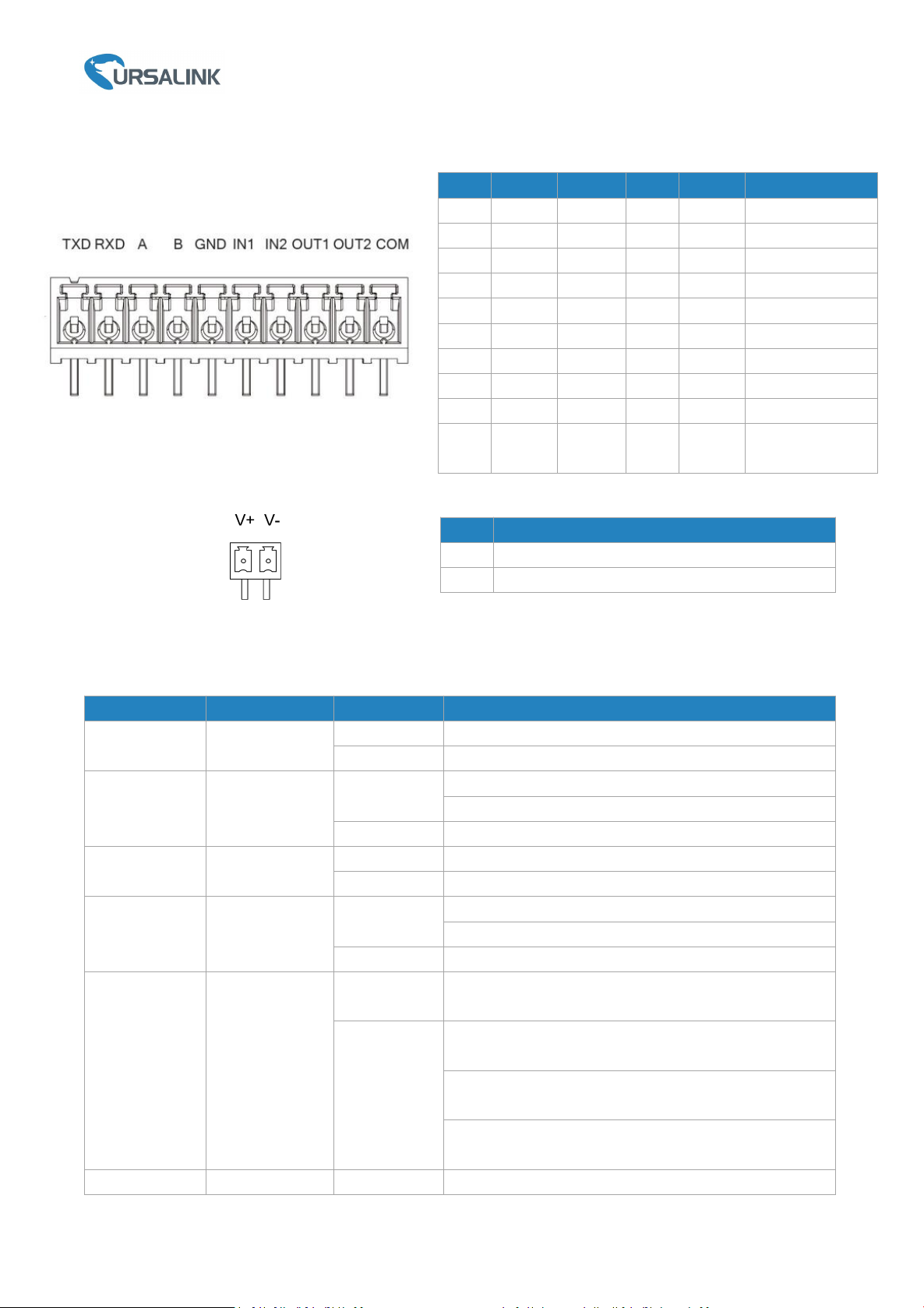
2.3 Pinouts
LED
Indication
Status
Description
POWER
Power Status
On
The power is switched on
Off
The power is switched off
STATUS
System Status
Green Light
Static: Start-up
Blinking slowly: the system is running properly
Red Light
The system goes wrong
VPN
VPN Status
Green Light
VPN is connected
Off
VPN is disconnected
WLAN (Wi-Fi)
WLAN Status
Green Light
Static: Wi-Fi is enabled
Blinking slowly: sending or receiving data via Wi-Fi
Off
Wi-Fi is disabled
SIM1/SIM2
SIM Card Status
Off
SIM1 or SIM2 is registering or fails to register (or
there are no SIM cards inserted)
Green Light
Blinking slowly: SIM1 or SIM2 has been registered
and is ready for dial-up
Blinking rapidly: SIM1 or SIM2 has been registered
and is dialing up now
Static: SIM1 or SIM2 has been registered and dialed
up successfully
Signal Strength
Signal 1/2/3
Off
No signal
PIN
RS232
RS485
DIDODescription
1
TXD
---
---
---
Transmit Data
2
RXD
---
---
---
Receive Data
3
---A---
---
Data +
4
---B---
---
Data -
5
GND
---
GND
---
Ground
6
---
---
IN1
---
Digital Input1
7
---
---
IN2
---
Digital Input2
8
---
---
---
OUT1
Digital Output1
9
---
---
---
OUT2
Digital Output2
10
---
---
---
COM
Common
Ground
PIN
Description
11
Positive
12
Negative
Ursalink UR75 Quick Start Guide
2.4 LED Indicators
www.ursalink.com
5
Green Light
Static/Off/Off: weak signals with 1-10 ASU (please
check if the antenna is installed correctly, or move the
antenna to a suitable location to get better signal)
Static/Static/Off: normal signals with 11-20 ASU
(average signal strength)
Static/Static/Static: strong signals with 21-31 ASU
(signal is good)
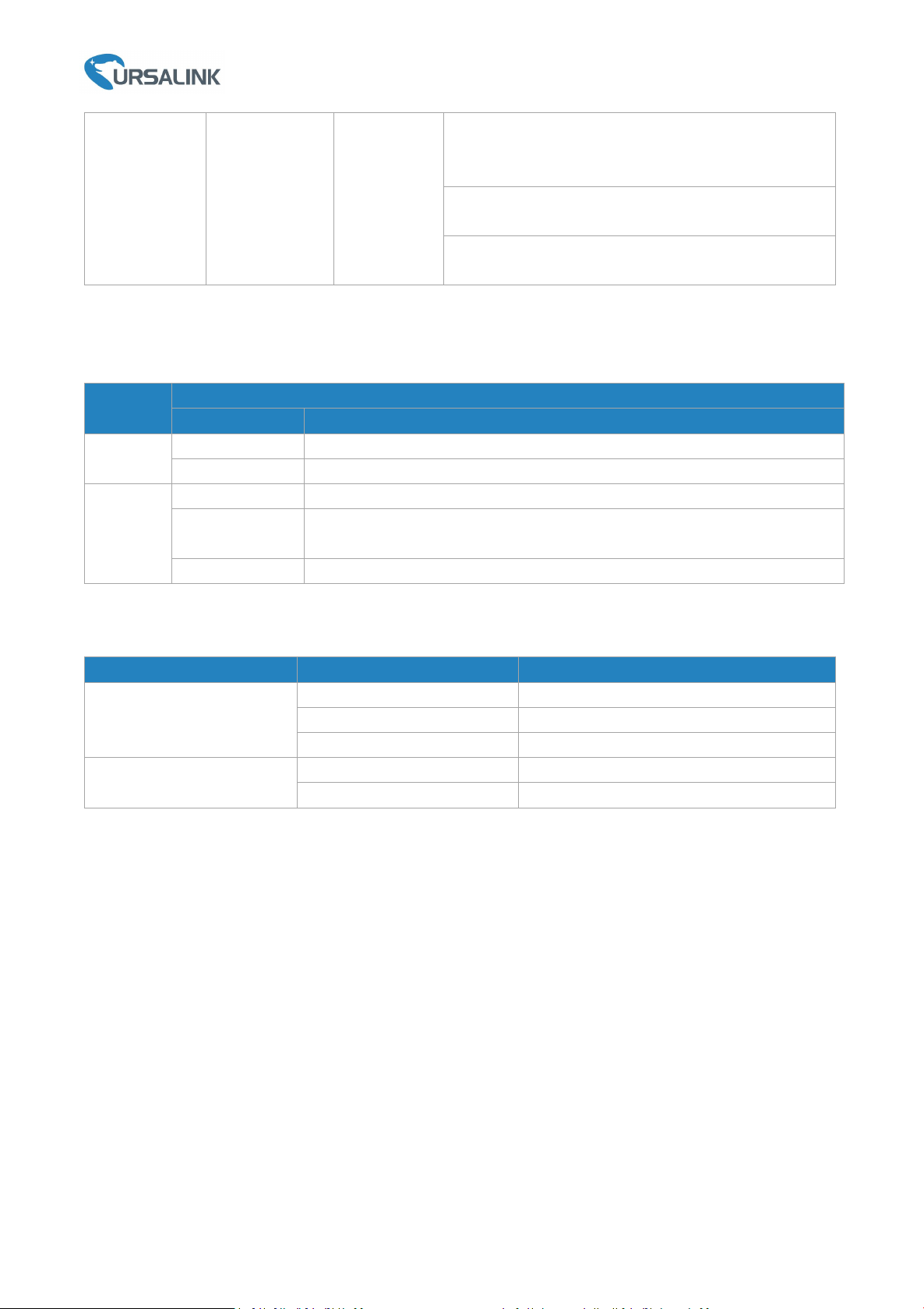
2.5 Reset Button
Function
Description
STATUS LED
Action
Reboot
Blinking
Press and hold the reset button for about 5-15 seconds.
Static Green
Release the button and wait for system to reboot.
Reset
Blinking
Press and hold the reset button for more than 15 seconds.
Static Green →
Rapidly Blinking
Release the button and wait.
Off → Blinking
The gateway is now reset to factory defaults.
Indicator
Status
Description
Link Indicator (Orange)
On
Connected
Blinking
Transmitting data
Off
Disconnected
Rate
Indicator (Green)
On
1000 Mbps mode
Off
100 Mbps mode
Ursalink UR75 Quick Start Guide
2.6 Ethernet Port Indicator
www.ursalink.com
 Loading...